

Page 1

FANUC Series 16/160/18/180 –Model B
for Machining Center
OPERATOR’S MANUAL
B-62454E/04
Page 2

• No part of this manual may be reproduced in any form.
• All specifications and designs are subject to change without notice.
The products in this manual are controlled based on Japan’s “Foreign Exchange and
Foreign Trade Law”. The export from Japan may be subject to an export license by the
government of Japan.
Further, re-export to another country may be subject to the license of the government of
the country from where the product is re-exported. Furthermore, the product may also be
controlled by re-export regulations of the United States government.
Should you wish to export or re-export these products, please contact FANUC for advice.
In this manual we have tried as much as possible to describe all the various matters.
However, we cannot describe all the matters which must not be done, or which cannot be
done, because there are so many possibilities.
Therefore, matters which are not especially described as possible in this manual should be
regarded as ”impossible”.
This manual contains the program names or device names of other companies, some of
which are registered trademarks of respective owners. However, these names are not
followed by ® or ™ in the main body.
Page 3

B–62454E/04
Table of Contents
I. GENERAL
1. GENERAL 3. . . . . . . . . . . . . . . . . . . . . . . . . . . . . . . . . . . . . . . . . . . . . . . . . . . . . . . . . . . . . .
1.1 GENERAL FLOW OF OPERATION OF CNC MACHINE TOOL 5. . . . . . . . . . . . . . . . . . . . . . . .
1.2 NOTES ON READING THIS MANUAL 7. . . . . . . . . . . . . . . . . . . . . . . . . . . . . . . . . . . . . . . . . . .
II. PROGRAMMING
1. GENERAL 11. . . . . . . . . . . . . . . . . . . . . . . . . . . . . . . . . . . . . . . . . . . . . . . . . . . . . . . . . . . . . .
1.1 TOOL MOVEMENT ALONG WORKPIECE PARTS FIGURE– INTERPOLATION 12. . . . . . . . .
1.2 FEED– FEED FUNCTION 14. . . . . . . . . . . . . . . . . . . . . . . . . . . . . . . . . . . . . . . . . . . . . . . . . . . . . . .
1.3 PART DRAWING AND TOOL MOVEMENT 15. . . . . . . . . . . . . . . . . . . . . . . . . . . . . . . . . . . . . . . .
1.3.1 Reference Position (Machine–Specific Position) 15. . . . . . . . . . . . . . . . . . . . . . . . . . . . . . . . . . . . . . . . .
1.3.2 Coordinate System on Part Drawing and Coordinate System Specified by CNC – Coordinate System 16
1.3.3 How to Indicate Command Dimensions for Moving the Tool – Absolute, Incremental Commands 19. .
1.4 CUTTING SPEED – SPINDLE SPEED FUNCTION 20. . . . . . . . . . . . . . . . . . . . . . . . . . . . . . . . . .
1.5 SELECTION OF TOOL USED FOR VARIOUS MACHINING – TOOL FUNCTION 21. . . . . . . .
1.6 COMMAND FOR MACHINE OPERATIONS – MISCELLANEOUS FUNCTION 22. . . . . . . . . .
1.7 PROGRAM CONFIGURATION 23. . . . . . . . . . . . . . . . . . . . . . . . . . . . . . . . . . . . . . . . . . . . . . . . . .
1.8 TOOL FIGURE AND TOOL MOTION BY PROGRAM 26. . . . . . . . . . . . . . . . . . . . . . . . . . . . . . .
1.9 TOOL MOVEMENT RANGE – STROKE 27. . . . . . . . . . . . . . . . . . . . . . . . . . . . . . . . . . . . . . . . . . .
2. CONTROLLED AXES 28. . . . . . . . . . . . . . . . . . . . . . . . . . . . . . . . . . . . . . . . . . . . . . . . . . . .
2.1 CONTROLLED AXES 29. . . . . . . . . . . . . . . . . . . . . . . . . . . . . . . . . . . . . . . . . . . . . . . . . . . . . . . . . .
2.2 AXIS NAME 29. . . . . . . . . . . . . . . . . . . . . . . . . . . . . . . . . . . . . . . . . . . . . . . . . . . . . . . . . . . . . . . . . .
2.3 INCREMENT SYSTEM 31. . . . . . . . . . . . . . . . . . . . . . . . . . . . . . . . . . . . . . . . . . . . . . . . . . . . . . . . .
2.4 MAXIMUM STROKE 32. . . . . . . . . . . . . . . . . . . . . . . . . . . . . . . . . . . . . . . . . . . . . . . . . . . . . . . . . .
3. PREPARATORY FUNCTION (G FUNCTION) 33. . . . . . . . . . . . . . . . . . . . . . . . . . . . . . .
4. INTERPOLATION FUNCTIONS 38. . . . . . . . . . . . . . . . . . . . . . . . . . . . . . . . . . . . . . . . . . .
4.1 POSITIONING (G00) 39. . . . . . . . . . . . . . . . . . . . . . . . . . . . . . . . . . . . . . . . . . . . . . . . . . . . . . . . . . .
4.2 SINGLE DIRECTION POSITIONING (G60) 41. . . . . . . . . . . . . . . . . . . . . . . . . . . . . . . . . . . . . . . .
4.3 LINEAR INTERPOLATION (G01) 43. . . . . . . . . . . . . . . . . . . . . . . . . . . . . . . . . . . . . . . . . . . . . . . .
4.4 CIRCULAR INTERPOLATION (G02,G03) 45. . . . . . . . . . . . . . . . . . . . . . . . . . . . . . . . . . . . . . . . . .
4.5 HELICAL INTERPOLATION (G02,G03) 49. . . . . . . . . . . . . . . . . . . . . . . . . . . . . . . . . . . . . . . . . . .
4.6 POLAR COORDINATE INTERPOLA TION (G12.1,G13.1) 50. . . . . . . . . . . . . . . . . . . . . . . . . . . . .
4.7 CYLINDRICAL INTERPOLATION (G07.1) 54. . . . . . . . . . . . . . . . . . . . . . . . . . . . . . . . . . . . . . . . .
4.8 INVOLUTE INTERPOLATION (G02.2, G03.2) 57. . . . . . . . . . . . . . . . . . . . . . . . . . . . . . . . . . . . . .
4.9 EXPONENTIAL INTERPOLATION (G02.3, G03.3) 63. . . . . . . . . . . . . . . . . . . . . . . . . . . . . . . . . .
4.10 THREADING (G33) 67. . . . . . . . . . . . . . . . . . . . . . . . . . . . . . . . . . . . . . . . . . . . . . . . . . . . . . . . . . . .
4.11 SKIP FUNCTION(G31) 69. . . . . . . . . . . . . . . . . . . . . . . . . . . . . . . . . . . . . . . . . . . . . . . . . . . . . . . . .
4.12 MULTISTAGE SKIP 71. . . . . . . . . . . . . . . . . . . . . . . . . . . . . . . . . . . . . . . . . . . . . . . . . . . . . . . . . . . .
5. FEED FUNCTIONS 72. . . . . . . . . . . . . . . . . . . . . . . . . . . . . . . . . . . . . . . . . . . . . . . . . . . . . .
5.1 GENERAL 73. . . . . . . . . . . . . . . . . . . . . . . . . . . . . . . . . . . . . . . . . . . . . . . . . . . . . . . . . . . . . . . . . . . .
Page 4

T ABLE OF CONTENTS
B–62454E/04
5.2 RAPID TRAVERSE 75. . . . . . . . . . . . . . . . . . . . . . . . . . . . . . . . . . . . . . . . . . . . . . . . . . . . . . . . . . . .
5.3 CUTTING FEED 76. . . . . . . . . . . . . . . . . . . . . . . . . . . . . . . . . . . . . . . . . . . . . . . . . . . . . . . . . . . . . . .
5.4 CUTTING FEEDRATE CONTROL 81. . . . . . . . . . . . . . . . . . . . . . . . . . . . . . . . . . . . . . . . . . . . . . . .
5.4.1 Exact Stop (G09, G61) Cutting Mode (G64) Tapping Mode (G63) 82. . . . . . . . . . . . . . . . . . . . . . . . . . .
5.4.2 Automatic Override for Inner Corners (G62) 83. . . . . . . . . . . . . . . . . . . . . . . . . . . . . . . . . . . . . . . . . . . .
5.4.3 Internal Circular Cutting Feedrate Change 85. . . . . . . . . . . . . . . . . . . . . . . . . . . . . . . . . . . . . . . . . . . . . .
5.4.4 AUTOMATIC CORNER DECELERATION 86. . . . . . . . . . . . . . . . . . . . . . . . . . . . . . . . . . . . . . . . . . . .
5.5 DWELL (G04) 93. . . . . . . . . . . . . . . . . . . . . . . . . . . . . . . . . . . . . . . . . . . . . . . . . . . . . . . . . . . . . . . . .
6. REFERENCE POSITION 94. . . . . . . . . . . . . . . . . . . . . . . . . . . . . . . . . . . . . . . . . . . . . . . . .
7. FLOATING REFERENCE POSITION RETURN (G30.1) 101. . . . . . . . . . . . . . . . . . . . . .
8. COORDINATE SYSTEM 103. . . . . . . . . . . . . . . . . . . . . . . . . . . . . . . . . . . . . . . . . . . . . . . . .
8.1 MACHINE COORDINATE SYSTEM 104. . . . . . . . . . . . . . . . . . . . . . . . . . . . . . . . . . . . . . . . . . . . . .
8.2 WORKPIECE COORDINATE SYSTEM 105. . . . . . . . . . . . . . . . . . . . . . . . . . . . . . . . . . . . . . . . . . . .
8.2.1 Setting a Workpiece Coordinate System 105. . . . . . . . . . . . . . . . . . . . . . . . . . . . . . . . . . . . . . . . . . . . . . . .
8.2.2 Selecting a Workpiece Coordinate System 106. . . . . . . . . . . . . . . . . . . . . . . . . . . . . . . . . . . . . . . . . . . . . .
8.2.3 Changing Workpiece Coordinate System 107. . . . . . . . . . . . . . . . . . . . . . . . . . . . . . . . . . . . . . . . . . . . . . .
8.2.4 Workpiece coordinate system preset (G92.1) 110. . . . . . . . . . . . . . . . . . . . . . . . . . . . . . . . . . . . . . . . . . . .
8.2.5 Adding Workpiece Coordinate Systems (G54.1 or G54) 112. . . . . . . . . . . . . . . . . . . . . . . . . . . . . . . . . . .
8.3 LOCAL COORDINATE SYSTEM 114. . . . . . . . . . . . . . . . . . . . . . . . . . . . . . . . . . . . . . . . . . . . . . . . .
8.4 PLANE SELECTION 116. . . . . . . . . . . . . . . . . . . . . . . . . . . . . . . . . . . . . . . . . . . . . . . . . . . . . . . . . . .
9. COORDINATE VALUE AND DIMENSION 117. . . . . . . . . . . . . . . . . . . . . . . . . . . . . . . . . .
9.1 ABSOLUTE AND INCREMENTAL PROGRAMMING (G90, G91) 118. . . . . . . . . . . . . . . . . . . . . .
9.2 POLAR COORDINATE COMMAND (G15, G16) 119. . . . . . . . . . . . . . . . . . . . . . . . . . . . . . . . . . . .
9.3 INCH/METRIC CONVERSION (G20,G21) 122. . . . . . . . . . . . . . . . . . . . . . . . . . . . . . . . . . . . . . . . .
9.4 DECIMAL POINT PROGRAMMING 123. . . . . . . . . . . . . . . . . . . . . . . . . . . . . . . . . . . . . . . . . . . . . .
10. SPINDLE SPEED FUNCTION (S FUNCTION) 124. . . . . . . . . . . . . . . . . . . . . . . . . . . . . .
10.1 SPECIFYING THE SPINDLE SPEED WITH A BINARY CODE 125. . . . . . . . . . . . . . . . . . . . . . . .
10.2 SPECIFYING THE SPINDLE SPEED VALUE DIRECTLY (S5–DIGIT COMMAND) 125. . . . . . .
10.3 CONSTANT SURFACE SPEED CONTROL (G96, G97) 126. . . . . . . . . . . . . . . . . . . . . . . . . . . . . . .
10.4 SPINDLE SPEED FLUCTUATION DETECTION FUNCTION (G25, G26) 129. . . . . . . . . . . . . . . .
11. TOOL FUNCTION (T FUNCTION) 132. . . . . . . . . . . . . . . . . . . . . . . . . . . . . . . . . . . . . . . . .
11.1 TOOL SELECTION FUNCTION 133. . . . . . . . . . . . . . . . . . . . . . . . . . . . . . . . . . . . . . . . . . . . . . . . . .
11.2 TOOL LIFE MANAGEMENT FUNCTION 134. . . . . . . . . . . . . . . . . . . . . . . . . . . . . . . . . . . . . . . . .
11.2.1 Tool Life Management Data 135. . . . . . . . . . . . . . . . . . . . . . . . . . . . . . . . . . . . . . . . . . . . . . . . . . . . . . . . .
11.2.2 Register, Change and Delete of Tool Life Management Data 136. . . . . . . . . . . . . . . . . . . . . . . . . . . . . . . .
11.2.3 Tool Life Management Command in a Machining Program 139. . . . . . . . . . . . . . . . . . . . . . . . . . . . . . . . .
11.2.4 Tool Life 142. . . . . . . . . . . . . . . . . . . . . . . . . . . . . . . . . . . . . . . . . . . . . . . . . . . . . . . . . . . . . . . . . . . . . . . .
12. AUXILIARY FUNCTION 143. . . . . . . . . . . . . . . . . . . . . . . . . . . . . . . . . . . . . . . . . . . . . . . . . .
12.1 AUXILIARY FUNCTION (M FUNCTION) 144. . . . . . . . . . . . . . . . . . . . . . . . . . . . . . . . . . . . . . . . .
12.2 MULTIPLE M COMMANDS IN A SINGLE BLOCK 145. . . . . . . . . . . . . . . . . . . . . . . . . . . . . . . . .
Page 5

B–62454E/04
T ABLE OF CONTENTS
12.3 M CODE GROUP CHECK FUNCTION 146. . . . . . . . . . . . . . . . . . . . . . . . . . . . . . . . . . . . . . . . . . . .
12.4 THE SECOND AUXILIARY FUNCTIONS (B CODES) 147. . . . . . . . . . . . . . . . . . . . . . . . . . . . . . .
13. PROGRAM CONFIGURATION 148. . . . . . . . . . . . . . . . . . . . . . . . . . . . . . . . . . . . . . . . . . . .
13.1 PROGRAM COMPONENTS OTHER THAN PROGRAM SECTIONS 150. . . . . . . . . . . . . . . . . . .
13.2 PROGRAM SECTION CONFIGURATION 153. . . . . . . . . . . . . . . . . . . . . . . . . . . . . . . . . . . . . . . . . .
13.3 SUBPROGRAM 159. . . . . . . . . . . . . . . . . . . . . . . . . . . . . . . . . . . . . . . . . . . . . . . . . . . . . . . . . . . . . . .
14. FUNCTIONS TO SIMPLIFY PROGRAMMING 163. . . . . . . . . . . . . . . . . . . . . . . . . . . . . .
14.1 CANNED CYCLE 164. . . . . . . . . . . . . . . . . . . . . . . . . . . . . . . . . . . . . . . . . . . . . . . . . . . . . . . . . . . . . .
14.1.1 High–speed Peck Drilling Cycle (G73) 168. . . . . . . . . . . . . . . . . . . . . . . . . . . . . . . . . . . . . . . . . . . . . . . . .
14.1.2 Left–handed Tapping Cycle (G74) 169. . . . . . . . . . . . . . . . . . . . . . . . . . . . . . . . . . . . . . . . . . . . . . . . . . . .
14.1.3 Fine Boring Cycle (G76) 172. . . . . . . . . . . . . . . . . . . . . . . . . . . . . . . . . . . . . . . . . . . . . . . . . . . . . . . . . . . .
14.1.4 Drilling Cycle, Spot Drilling (G81) 174. . . . . . . . . . . . . . . . . . . . . . . . . . . . . . . . . . . . . . . . . . . . . . . . . . . .
14.1.5 Drilling Cycle Counter Boring Cycle (G82) 176. . . . . . . . . . . . . . . . . . . . . . . . . . . . . . . . . . . . . . . . . . . . .
14.1.6 Peck Drilling Cycle (G83) 178. . . . . . . . . . . . . . . . . . . . . . . . . . . . . . . . . . . . . . . . . . . . . . . . . . . . . . . . . . .
14.1.7 Small–hole peck drilling cycle (G83) 180. . . . . . . . . . . . . . . . . . . . . . . . . . . . . . . . . . . . . . . . . . . . . . . . . .
14.1.8 Tapping Cycle (G84) 184. . . . . . . . . . . . . . . . . . . . . . . . . . . . . . . . . . . . . . . . . . . . . . . . . . . . . . . . . . . . . . .
14.1.9 Boring Cycle (G85) 187. . . . . . . . . . . . . . . . . . . . . . . . . . . . . . . . . . . . . . . . . . . . . . . . . . . . . . . . . . . . . . . .
14.1.10 Boring Cycle (G86) 189. . . . . . . . . . . . . . . . . . . . . . . . . . . . . . . . . . . . . . . . . . . . . . . . . . . . . . . . . . . . . . . .
14.1.11 Boring Cycle Back Boring Cycle (G87) 191. . . . . . . . . . . . . . . . . . . . . . . . . . . . . . . . . . . . . . . . . . . . . . . .
14.1.12 Boring Cycle (G88) 193. . . . . . . . . . . . . . . . . . . . . . . . . . . . . . . . . . . . . . . . . . . . . . . . . . . . . . . . . . . . . . . .
14.1.13 Boring Cycle (G89) 195. . . . . . . . . . . . . . . . . . . . . . . . . . . . . . . . . . . . . . . . . . . . . . . . . . . . . . . . . . . . . . . .
14.1.14 Canned Cycle Cancel (G80) 196. . . . . . . . . . . . . . . . . . . . . . . . . . . . . . . . . . . . . . . . . . . . . . . . . . . . . . . . .
14.2 RIGID TAPPING 199. . . . . . . . . . . . . . . . . . . . . . . . . . . . . . . . . . . . . . . . . . . . . . . . . . . . . . . . . . . . . . .
14.2.1 Rigid Tapping (G84) 199. . . . . . . . . . . . . . . . . . . . . . . . . . . . . . . . . . . . . . . . . . . . . . . . . . . . . . . . . . . . . . .
14.2.2 Left–handed Rigid Tapping Cycle (G74) 201. . . . . . . . . . . . . . . . . . . . . . . . . . . . . . . . . . . . . . . . . . . . . . .
14.2.3 Peck Rigid Tapping Cycle (G84 or G74) 204. . . . . . . . . . . . . . . . . . . . . . . . . . . . . . . . . . . . . . . . . . . . . . .
14.2.4 Canned Cycle Cancel (G80) 206. . . . . . . . . . . . . . . . . . . . . . . . . . . . . . . . . . . . . . . . . . . . . . . . . . . . . . . . .
14.3 CANNED GRINDING CYCLE (FOR GRINDING MACHINE) 207. . . . . . . . . . . . . . . . . . . . . . . . .
14.3.1 Plunge Grinding Cycle (G75) 207. . . . . . . . . . . . . . . . . . . . . . . . . . . . . . . . . . . . . . . . . . . . . . . . . . . . . . . .
14.3.2 Direct Constant–dimension Plunge Grinding Cycle (G77) 210. . . . . . . . . . . . . . . . . . . . . . . . . . . . . . . . . .
14.3.3 Continuous–feed Surface Grinding Cycle (G78) 212. . . . . . . . . . . . . . . . . . . . . . . . . . . . . . . . . . . . . . . . .
14.3.4 Intermittent–feed Surface Grinding Cycle (G79) 214. . . . . . . . . . . . . . . . . . . . . . . . . . . . . . . . . . . . . . . . .
14.4 GRINDING– WHEEL WEAR COMPENSATION BY CONTINUOUS DRESSING
(FOR GRINDING MACHINE) 216. . . . . . . . . . . . . . . . . . . . . . . . . . . . . . . . . . . . . . . . . . . . . . . . . . . .
14.5 AUTOMATIC GRINDING WHEEL DIAMETER COMPENSATION AFTER DRESSING 217. . .
14.5.1 Checking the Minimum Grinding Wheel Diameter (for grinding machine) 217. . . . . . . . . . . . . . . . . . . . .
14.6 IN–FEED GRINDING ALONG THE Y AND Z AXES AT THE END OF TABLE SWING
(FOR GRINDING MACHINE) 218. . . . . . . . . . . . . . . . . . . . . . . . . . . . . . . . . . . . . . . . . . . . . . . . . . . .
14.7 OPTIONAL ANGLE CHAMFERING AND CORNER ROUNDING 220. . . . . . . . . . . . . . . . . . . . .
14.8 EXTERNAL MOTION FUNCTION (G81) 223. . . . . . . . . . . . . . . . . . . . . . . . . . . . . . . . . . . . . . . . . .
14.9 FIGURE COPY (G72.1, G72.2) 224. . . . . . . . . . . . . . . . . . . . . . . . . . . . . . . . . . . . . . . . . . . . . . . . . . .
14.10 THREE– DIMENTIONAL COORDINATE CONVERSION (G68, G69) 231. . . . . . . . . . . . . . . . . . .
15. COMPENSATION FUNCTION 238. . . . . . . . . . . . . . . . . . . . . . . . . . . . . . . . . . . . . . . . . . . .
15.1 TOOL LENGTH OFFSET (G43,G44,G49) 239. . . . . . . . . . . . . . . . . . . . . . . . . . . . . . . . . . . . . . . . . .
15.1.1 General 239. . . . . . . . . . . . . . . . . . . . . . . . . . . . . . . . . . . . . . . . . . . . . . . . . . . . . . . . . . . . . . . . . . . . . . . . .
15.1.2 G53, G28, G30, and G30.1 Commands in Tool Length Offset Mode 244. . . . . . . . . . . . . . . . . . . . . . . . . .
Page 6

T ABLE OF CONTENTS
B–62454E/04
15.2 AUTOMATIC TOOL LENGTH MEASUREMENT (G37) 247. . . . . . . . . . . . . . . . . . . . . . . . . . . . . .
15.3 TOOL OFFSET (G45–G48) 250. . . . . . . . . . . . . . . . . . . . . . . . . . . . . . . . . . . . . . . . . . . . . . . . . . . . . .
15.4 CUTTER COMPENSATION B (G39 – G42) 255. . . . . . . . . . . . . . . . . . . . . . . . . . . . . . . . . . . . . . . . .
15.4.1 Cutter Compensation Left (G41) 258. . . . . . . . . . . . . . . . . . . . . . . . . . . . . . . . . . . . . . . . . . . . . . . . . . . . . .
15.4.2 Cutter Compensation Right (G42) 260. . . . . . . . . . . . . . . . . . . . . . . . . . . . . . . . . . . . . . . . . . . . . . . . . . . .
15.4.3 Corner Offset Circular Interpolation (G39) 262. . . . . . . . . . . . . . . . . . . . . . . . . . . . . . . . . . . . . . . . . . . . . .
15.4.4 Cutter Compensation Cancel (G40) 263. . . . . . . . . . . . . . . . . . . . . . . . . . . . . . . . . . . . . . . . . . . . . . . . . . .
15.4.5 Switch between Cutter Compensation Left and Cutter Compensation Right 264. . . . . . . . . . . . . . . . . . . .
15.4.6 Change of the Cutter Compensation Value 265. . . . . . . . . . . . . . . . . . . . . . . . . . . . . . . . . . . . . . . . . . . . . .
15.4.7 Positive/Negative Cutter Compensation Value and Tool Center Path 266. . . . . . . . . . . . . . . . . . . . . . . . . .
15.5 OVERVIEW OF CUTTER COMPENSATION C (G40 – G42) 268. . . . . . . . . . . . . . . . . . . . . . . . . . .
15.6 DETAILS OF CUTTER COMPENSATION C 274. . . . . . . . . . . . . . . . . . . . . . . . . . . . . . . . . . . . . . . .
15.6.1 General 274. . . . . . . . . . . . . . . . . . . . . . . . . . . . . . . . . . . . . . . . . . . . . . . . . . . . . . . . . . . . . . . . . . . . . . . . .
15.6.2 Tool Movement in Start–up 275. . . . . . . . . . . . . . . . . . . . . . . . . . . . . . . . . . . . . . . . . . . . . . . . . . . . . . . . . .
15.6.3 Tool Movement in Offset Mode 279. . . . . . . . . . . . . . . . . . . . . . . . . . . . . . . . . . . . . . . . . . . . . . . . . . . . . .
15.6.4 Tool Movement in Offset Mode Cancel 293. . . . . . . . . . . . . . . . . . . . . . . . . . . . . . . . . . . . . . . . . . . . . . . .
15.6.5 Interference Check 299. . . . . . . . . . . . . . . . . . . . . . . . . . . . . . . . . . . . . . . . . . . . . . . . . . . . . . . . . . . . . . . .
15.6.6 Overcutting by Cutter Compensation 304. . . . . . . . . . . . . . . . . . . . . . . . . . . . . . . . . . . . . . . . . . . . . . . . . .
15.6.7 Input Command from MDI 307. . . . . . . . . . . . . . . . . . . . . . . . . . . . . . . . . . . . . . . . . . . . . . . . . . . . . . . . . .
15.6.8 G53,G28,G30,G30.1 and G29 Commands in Cutter Compensation C Mode 308. . . . . . . . . . . . . . . . . . .
15.7 THREE– DIMENSIONAL TOOL COMPENSATION (G40, G41) 327. . . . . . . . . . . . . . . . . . . . . . . .
15.8 TOOL COMPENSA– TION VALUES, NUMBER OF COMPENSATION VALUES, AND
ENTERING VALUES FROM THE PROGRAM (G10) 331. . . . . . . . . . . . . . . . . . . . . . . . . . . . . . . . .
15.9 SCALING (G50,G51) 333. . . . . . . . . . . . . . . . . . . . . . . . . . . . . . . . . . . . . . . . . . . . . . . . . . . . . . . . . . .
15.10 COORDINATE SYSTEM ROTATION (G68, G69) 338. . . . . . . . . . . . . . . . . . . . . . . . . . . . . . . . . . . .
15.11 INDEX T ABLE INDEXING FUNCTION 344. . . . . . . . . . . . . . . . . . . . . . . . . . . . . . . . . . . . . . . . . . .
15.12 NORMAL DIRECTION CONTROL (G40.1, G41.1, G42.1 OR G150, G151, G152) 347. . . . . . . . .
15.13 PROGRAMMABLE MIRROR IMAGE (G50.1, G51.1) 352. . . . . . . . . . . . . . . . . . . . . . . . . . . . . . . .
16. CUSTOM MACRO 354. . . . . . . . . . . . . . . . . . . . . . . . . . . . . . . . . . . . . . . . . . . . . . . . . . . . . . .
16.1 VARIABLES 355. . . . . . . . . . . . . . . . . . . . . . . . . . . . . . . . . . . . . . . . . . . . . . . . . . . . . . . . . . . . . . . . . .
16.2 SYSTEM VARIABLES 359. . . . . . . . . . . . . . . . . . . . . . . . . . . . . . . . . . . . . . . . . . . . . . . . . . . . . . . . . .
16.3 ARITHMETIC AND LOGIC OPERATION 367. . . . . . . . . . . . . . . . . . . . . . . . . . . . . . . . . . . . . . . . . .
16.4 MACRO STATEMENTS AND NC STATEMENTS 371. . . . . . . . . . . . . . . . . . . . . . . . . . . . . . . . . . .
16.5 BRANCH AND REPETITION 372. . . . . . . . . . . . . . . . . . . . . . . . . . . . . . . . . . . . . . . . . . . . . . . . . . . .
16.5.1 Unconditional Branch (GOTO Statement) 372. . . . . . . . . . . . . . . . . . . . . . . . . . . . . . . . . . . . . . . . . . . . . .
16.5.2 Conditional Branch (IF Statement) 372. . . . . . . . . . . . . . . . . . . . . . . . . . . . . . . . . . . . . . . . . . . . . . . . . . . .
16.5.3 Repetition (While Statement) 373. . . . . . . . . . . . . . . . . . . . . . . . . . . . . . . . . . . . . . . . . . . . . . . . . . . . . . . .
16.6 MACRO CALL 376. . . . . . . . . . . . . . . . . . . . . . . . . . . . . . . . . . . . . . . . . . . . . . . . . . . . . . . . . . . . . . . .
16.6.1 Simple Call (G65) 376. . . . . . . . . . . . . . . . . . . . . . . . . . . . . . . . . . . . . . . . . . . . . . . . . . . . . . . . . . . . . . . . .
16.6.2 Modal Call (G66) 380. . . . . . . . . . . . . . . . . . . . . . . . . . . . . . . . . . . . . . . . . . . . . . . . . . . . . . . . . . . . . . . . .
16.6.3 Macro Call Using G Code 382. . . . . . . . . . . . . . . . . . . . . . . . . . . . . . . . . . . . . . . . . . . . . . . . . . . . . . . . . . .
16.6.4 Macro Call Using an M Code 383. . . . . . . . . . . . . . . . . . . . . . . . . . . . . . . . . . . . . . . . . . . . . . . . . . . . . . . .
16.6.5 Subprogram Call Using an M Code 384. . . . . . . . . . . . . . . . . . . . . . . . . . . . . . . . . . . . . . . . . . . . . . . . . . .
16.6.6 Subprogram Calls Using a T Code 385. . . . . . . . . . . . . . . . . . . . . . . . . . . . . . . . . . . . . . . . . . . . . . . . . . . .
16.6.7 Sample Program 386. . . . . . . . . . . . . . . . . . . . . . . . . . . . . . . . . . . . . . . . . . . . . . . . . . . . . . . . . . . . . . . . . .
16.7 PROCESSING MACRO STATEMENTS 388. . . . . . . . . . . . . . . . . . . . . . . . . . . . . . . . . . . . . . . . . . . .
16.8 REGISTERING CUSTOM MACRO PROGRAMS 390. . . . . . . . . . . . . . . . . . . . . . . . . . . . . . . . . . . .
16.9 LIMITA TIONS 391. . . . . . . . . . . . . . . . . . . . . . . . . . . . . . . . . . . . . . . . . . . . . . . . . . . . . . . . . . . . . . . . .
Page 7

B–62454E/04
16.10 EXTERNAL OUTPUT COMMANDS 392. . . . . . . . . . . . . . . . . . . . . . . . . . . . . . . . . . . . . . . . . . . . . .
16.11 INTERRUPTION TYPE CUSTOM MACRO 396. . . . . . . . . . . . . . . . . . . . . . . . . . . . . . . . . . . . . . . .
16.11.1 Specification Method 397. . . . . . . . . . . . . . . . . . . . . . . . . . . . . . . . . . . . . . . . . . . . . . . . . . . . . . . . . . . . . .
16.11.2 Details of Functions 398. . . . . . . . . . . . . . . . . . . . . . . . . . . . . . . . . . . . . . . . . . . . . . . . . . . . . . . . . . . . . . . .
T ABLE OF CONTENTS
17. PATTERN DATA INPUT FUNCTION 406. . . . . . . . . . . . . . . . . . . . . . . . . . . . . . . . . . . . . . .
17.1 DISPLAYING THE PATTERN MENU 407. . . . . . . . . . . . . . . . . . . . . . . . . . . . . . . . . . . . . . . . . . . . .
17.2 PATTERN DA TA DISPLAY 411. . . . . . . . . . . . . . . . . . . . . . . . . . . . . . . . . . . . . . . . . . . . . . . . . . . . . .
17.3 CHARACTERS AND CODES TO BE USED FOR THE PATTERN DATA INPUT FUNCTION 415
18. PROGRAMMABLE PARAMETER ENTRY (G10) 417. . . . . . . . . . . . . . . . . . . . . . . . . . . .
19. MEMORY OPERATION USING FS15 TAPE FORMAT 419. . . . . . . . . . . . . . . . . . . . . . .
20. HIGH SPEED CUTTING FUNCTIONS 420. . . . . . . . . . . . . . . . . . . . . . . . . . . . . . . . . . . . .
20.1 HIGH–SPEED CYCLE CUTTING 421. . . . . . . . . . . . . . . . . . . . . . . . . . . . . . . . . . . . . . . . . . . . . . . . .
20.2 FEEDRATE CLAMPING BY ARC RADIUS 423. . . . . . . . . . . . . . . . . . . . . . . . . . . . . . . . . . . . . . . .
20.3 LOOK–AHEAD CONTROL (G08) 424. . . . . . . . . . . . . . . . . . . . . . . . . . . . . . . . . . . . . . . . . . . . . . . .
20.4 HIGH–SPEED REMOTE BUFFER 426. . . . . . . . . . . . . . . . . . . . . . . . . . . . . . . . . . . . . . . . . . . . . . . .
20.4.1 High–speed remote buffer A (G05) 426. . . . . . . . . . . . . . . . . . . . . . . . . . . . . . . . . . . . . . . . . . . . . . . . . . . .
20.4.2 High–speed remote buffer B (G05) 429. . . . . . . . . . . . . . . . . . . . . . . . . . . . . . . . . . . . . . . . . . . . . . . . . . . .
20.5 HIGH–PRECISION CONTOUR CONTROL 430. . . . . . . . . . . . . . . . . . . . . . . . . . . . . . . . . . . . . . . . .
20.6 DISTRIBUTION PROCESSING TERMINATION MONITORING FUNCTION FOR THE
HIGH–SPEED MACHINING COMMAND (G05) 439. . . . . . . . . . . . . . . . . . . . . . . . . . . . . . . . . . . .
21. AXIS CONTROL FUNCTIONS 440. . . . . . . . . . . . . . . . . . . . . . . . . . . . . . . . . . . . . . . . . . . .
21.1 SYMPLE SYNCHRONOUS CONTROL 441. . . . . . . . . . . . . . . . . . . . . . . . . . . . . . . . . . . . . . . . . . . .
21.2 ROTARY AXIS ROLL–OVER 444. . . . . . . . . . . . . . . . . . . . . . . . . . . . . . . . . . . . . . . . . . . . . . . . . . . .
21.3 TOOL WITHDRAWAL AND RETURN (G10.6) 445. . . . . . . . . . . . . . . . . . . . . . . . . . . . . . . . . . . . . .
21.4 T ANDEM CONTROL 448. . . . . . . . . . . . . . . . . . . . . . . . . . . . . . . . . . . . . . . . . . . . . . . . . . . . . . . . . . .
21.5 ANGULAR AXIS CONTROL 449. . . . . . . . . . . . . . . . . . . . . . . . . . . . . . . . . . . . . . . . . . . . . . . . . . . .
22. TWO–PATH CONTROL FUNCTION 451. . . . . . . . . . . . . . . . . . . . . . . . . . . . . . . . . . . . . . .
22.1 GENERAL 452. . . . . . . . . . . . . . . . . . . . . . . . . . . . . . . . . . . . . . . . . . . . . . . . . . . . . . . . . . . . . . . . . . . .
22.2 WAITING FOR PA THS 453. . . . . . . . . . . . . . . . . . . . . . . . . . . . . . . . . . . . . . . . . . . . . . . . . . . . . . . . . .
22.3 MEMOR Y COMMON TO PATH 455. . . . . . . . . . . . . . . . . . . . . . . . . . . . . . . . . . . . . . . . . . . . . . . . . .
III. OPERATION
1. GENERAL 459. . . . . . . . . . . . . . . . . . . . . . . . . . . . . . . . . . . . . . . . . . . . . . . . . . . . . . . . . . . . . .
1.1 MANUAL OPERATION 460. . . . . . . . . . . . . . . . . . . . . . . . . . . . . . . . . . . . . . . . . . . . . . . . . . . . . . . . .
1.2 TOOL MOVEMENT BY PROGRAMING – AUTOMATIC OPERATION 462. . . . . . . . . . . . . . . . .
1.3 AUTOMATIC OPERATION 463. . . . . . . . . . . . . . . . . . . . . . . . . . . . . . . . . . . . . . . . . . . . . . . . . . . . . .
1.4 TESTING A PROGRAM 465. . . . . . . . . . . . . . . . . . . . . . . . . . . . . . . . . . . . . . . . . . . . . . . . . . . . . . . .
1.4.1 Check by Running the Machine 465. . . . . . . . . . . . . . . . . . . . . . . . . . . . . . . . . . . . . . . . . . . . . . . . . . . . . .
1.4.2 How to View the Position Display Change without Running the Machine 466. . . . . . . . . . . . . . . . . . . . .
Page 8

T ABLE OF CONTENTS
B–62454E/04
1.5 EDITING A PART PROGRAM 467. . . . . . . . . . . . . . . . . . . . . . . . . . . . . . . . . . . . . . . . . . . . . . . . . . .
1.6 DISPLAYING AND SETTING DATA 468. . . . . . . . . . . . . . . . . . . . . . . . . . . . . . . . . . . . . . . . . . . . . .
1.7 DISPLAY 471. . . . . . . . . . . . . . . . . . . . . . . . . . . . . . . . . . . . . . . . . . . . . . . . . . . . . . . . . . . . . . . . . . . . .
1.7.1 Program Display 471. . . . . . . . . . . . . . . . . . . . . . . . . . . . . . . . . . . . . . . . . . . . . . . . . . . . . . . . . . . . . . . . . .
1.7.2 Current Position Display 472. . . . . . . . . . . . . . . . . . . . . . . . . . . . . . . . . . . . . . . . . . . . . . . . . . . . . . . . . . . .
1.7.3 Alarm Display 472. . . . . . . . . . . . . . . . . . . . . . . . . . . . . . . . . . . . . . . . . . . . . . . . . . . . . . . . . . . . . . . . . . .
1.7.4 Parts Count Display, Run Time Display 473. . . . . . . . . . . . . . . . . . . . . . . . . . . . . . . . . . . . . . . . . . . . . . . .
1.7.5 Graphic Display 473. . . . . . . . . . . . . . . . . . . . . . . . . . . . . . . . . . . . . . . . . . . . . . . . . . . . . . . . . . . . . . . . . . .
1.8 DATA INPUT / OUTPUT 474. . . . . . . . . . . . . . . . . . . . . . . . . . . . . . . . . . . . . . . . . . . . . . . . . . . . . . . .
2. OPERATIONAL DEVICES 475. . . . . . . . . . . . . . . . . . . . . . . . . . . . . . . . . . . . . . . . . . . . . . . .
2.1 CR T/MDI AND LCD/MDI 476. . . . . . . . . . . . . . . . . . . . . . . . . . . . . . . . . . . . . . . . . . . . . . . . . . . . . . .
2.1.1 9” Monochrome/Color CRT/MDI Panel (small type) 477. . . . . . . . . . . . . . . . . . . . . . . . . . . . . . . . . . . . . .
2.1.2 9” Monochrome/Color CRT/MDI Panel (standard type) 477. . . . . . . . . . . . . . . . . . . . . . . . . . . . . . . . . . .
2.1.3 9” Monochrome PDP/MDI (standard type) 478. . . . . . . . . . . . . . . . . . . . . . . . . . . . . . . . . . . . . . . . . . . . .
2.1.4 14” Color CRT/MDI (Horizontal type) 478. . . . . . . . . . . . . . . . . . . . . . . . . . . . . . . . . . . . . . . . . . . . . . . . .
2.1.5 14” Color CRT/MDI (Vertical type) 479. . . . . . . . . . . . . . . . . . . . . . . . . . . . . . . . . . . . . . . . . . . . . . . . . . .
2.1.6 9” Monochrome/Color CRT (separate type) 480. . . . . . . . . . . . . . . . . . . . . . . . . . . . . . . . . . . . . . . . . . . . .
2.1.7 9” Monochrome PDP (separate type) 481. . . . . . . . . . . . . . . . . . . . . . . . . . . . . . . . . . . . . . . . . . . . . . . . . .
2.1.8 7.2” Monochrome LCD (separate type) 482. . . . . . . . . . . . . . . . . . . . . . . . . . . . . . . . . . . . . . . . . . . . . . . .
2.1.9 8.4” Color LCD (separate type) 483. . . . . . . . . . . . . . . . . . . . . . . . . . . . . . . . . . . . . . . . . . . . . . . . . . . . . .
2.1.10 9.5” Color LCD/MDI (horizontal type) 484. . . . . . . . . . . . . . . . . . . . . . . . . . . . . . . . . . . . . . . . . . . . . . . . .
2.1.11 9.5” Color LCD/MDI (vertical type) 485. . . . . . . . . . . . . . . . . . . . . . . . . . . . . . . . . . . . . . . . . . . . . . . . . . .
2.1.12 Separate Type MDI (small type) 486. . . . . . . . . . . . . . . . . . . . . . . . . . . . . . . . . . . . . . . . . . . . . . . . . . . . . .
2.1.13 Separate Type MDI (standard type) 487. . . . . . . . . . . . . . . . . . . . . . . . . . . . . . . . . . . . . . . . . . . . . . . . . . .
2.2 EXPLANATION OF THE KEYBOARD 488. . . . . . . . . . . . . . . . . . . . . . . . . . . . . . . . . . . . . . . . . . . .
2.3 FUNCTION KEYS AND SOFT KEYS 490. . . . . . . . . . . . . . . . . . . . . . . . . . . . . . . . . . . . . . . . . . . . .
2.3.1 General Screen Operations 490. . . . . . . . . . . . . . . . . . . . . . . . . . . . . . . . . . . . . . . . . . . . . . . . . . . . . . . . . .
2.3.2 Function Keys 491. . . . . . . . . . . . . . . . . . . . . . . . . . . . . . . . . . . . . . . . . . . . . . . . . . . . . . . . . . . . . . . . . . . .
2.3.3 Soft Keys 492. . . . . . . . . . . . . . . . . . . . . . . . . . . . . . . . . . . . . . . . . . . . . . . . . . . . . . . . . . . . . . . . . . . . . . . .
2.3.4 Key Input and Input Buffer 509. . . . . . . . . . . . . . . . . . . . . . . . . . . . . . . . . . . . . . . . . . . . . . . . . . . . . . . . . .
2.3.5 Warning Messages 510. . . . . . . . . . . . . . . . . . . . . . . . . . . . . . . . . . . . . . . . . . . . . . . . . . . . . . . . . . . . . . . . .
2.3.6 14” CRT, 9.5” LCD, and 8.4” LCD Soft Key Configuration 511. . . . . . . . . . . . . . . . . . . . . . . . . . . . . . . .
2.4 EXTERNAL I/O DEVICES 512. . . . . . . . . . . . . . . . . . . . . . . . . . . . . . . . . . . . . . . . . . . . . . . . . . . . . .
2.4.1 FANUC Handy File 514. . . . . . . . . . . . . . . . . . . . . . . . . . . . . . . . . . . . . . . . . . . . . . . . . . . . . . . . . . . . . . . .
2.4.2 FANUC Floppy Cassette 514. . . . . . . . . . . . . . . . . . . . . . . . . . . . . . . . . . . . . . . . . . . . . . . . . . . . . . . . . . . .
2.4.3 FANUC FA Card 515. . . . . . . . . . . . . . . . . . . . . . . . . . . . . . . . . . . . . . . . . . . . . . . . . . . . . . . . . . . . . . . . . .
2.4.4 FANUC PPR 515. . . . . . . . . . . . . . . . . . . . . . . . . . . . . . . . . . . . . . . . . . . . . . . . . . . . . . . . . . . . . . . . . . . . .
2.4.5 Portable Tape Reader 516. . . . . . . . . . . . . . . . . . . . . . . . . . . . . . . . . . . . . . . . . . . . . . . . . . . . . . . . . . . . . . .
2.5 POWER ON/OFF 517. . . . . . . . . . . . . . . . . . . . . . . . . . . . . . . . . . . . . . . . . . . . . . . . . . . . . . . . . . . . . .
2.5.1 Turning on the Power 517. . . . . . . . . . . . . . . . . . . . . . . . . . . . . . . . . . . . . . . . . . . . . . . . . . . . . . . . . . . . . .
2.5.2 Screen Displayed at Power–on 518. . . . . . . . . . . . . . . . . . . . . . . . . . . . . . . . . . . . . . . . . . . . . . . . . . . . . . .
2.5.3 Power Disconnection 519. . . . . . . . . . . . . . . . . . . . . . . . . . . . . . . . . . . . . . . . . . . . . . . . . . . . . . . . . . . . . . .
3. Manual operation 520. . . . . . . . . . . . . . . . . . . . . . . . . . . . . . . . . . . . . . . . . . . . . . . . . . . . . . .
3.1 MANUAL REFERENCE POSITION RETURN 521. . . . . . . . . . . . . . . . . . . . . . . . . . . . . . . . . . . . . .
3.2 MANUAL CONTINUOUS FEED (JOG) 523. . . . . . . . . . . . . . . . . . . . . . . . . . . . . . . . . . . . . . . . . . . .
3.3 INCREMENTAL FEED 525. . . . . . . . . . . . . . . . . . . . . . . . . . . . . . . . . . . . . . . . . . . . . . . . . . . . . . . . .
3.4 MANUAL HANDLE FEED 526. . . . . . . . . . . . . . . . . . . . . . . . . . . . . . . . . . . . . . . . . . . . . . . . . . . . . .
Page 9

B–62454E/04
3.5 MANUAL ABSOLUTE ON AND OFF 529. . . . . . . . . . . . . . . . . . . . . . . . . . . . . . . . . . . . . . . . . . . . .
3.6 TOOL AXIS DIRECTION HANDLE FEED 534. . . . . . . . . . . . . . . . . . . . . . . . . . . . . . . . . . . . . . . . .
T ABLE OF CONTENTS
4. AUTOMATIC OPERATION 538. . . . . . . . . . . . . . . . . . . . . . . . . . . . . . . . . . . . . . . . . . . . . . .
4.1 MEMOR Y OPERATION 539. . . . . . . . . . . . . . . . . . . . . . . . . . . . . . . . . . . . . . . . . . . . . . . . . . . . . . . . .
4.2 MDI OPERATION 542. . . . . . . . . . . . . . . . . . . . . . . . . . . . . . . . . . . . . . . . . . . . . . . . . . . . . . . . . . . . . .
4.3 PROGRAM REST ART 546. . . . . . . . . . . . . . . . . . . . . . . . . . . . . . . . . . . . . . . . . . . . . . . . . . . . . . . . . .
4.4 SCHEDULING FUNCTION 553. . . . . . . . . . . . . . . . . . . . . . . . . . . . . . . . . . . . . . . . . . . . . . . . . . . . . .
4.5 SUBPROGRAM CALL FUNCTION 558. . . . . . . . . . . . . . . . . . . . . . . . . . . . . . . . . . . . . . . . . . . . . . .
4.6 MANUAL HANDLE INTERRUPTION 560. . . . . . . . . . . . . . . . . . . . . . . . . . . . . . . . . . . . . . . . . . . .
4.7 MIRROR IMAGE 563. . . . . . . . . . . . . . . . . . . . . . . . . . . . . . . . . . . . . . . . . . . . . . . . . . . . . . . . . . . . . .
4.8 TOOL WITHDRAWAL AND RETURN 565. . . . . . . . . . . . . . . . . . . . . . . . . . . . . . . . . . . . . . . . . . . .
4.9 RETRACE FUNCTION 571. . . . . . . . . . . . . . . . . . . . . . . . . . . . . . . . . . . . . . . . . . . . . . . . . . . . . . . . .
4.10 MANUAL INTERVENTION AND RETURN 579. . . . . . . . . . . . . . . . . . . . . . . . . . . . . . . . . . . . . . . .
4.11 DNC OPERATION 581. . . . . . . . . . . . . . . . . . . . . . . . . . . . . . . . . . . . . . . . . . . . . . . . . . . . . . . . . . . . .
4.12 SIMULTANEOUS INPUT/OUTPUT 584. . . . . . . . . . . . . . . . . . . . . . . . . . . . . . . . . . . . . . . . . . . . . . .
5. TEST OPERATION 586. . . . . . . . . . . . . . . . . . . . . . . . . . . . . . . . . . . . . . . . . . . . . . . . . . . . . .
5.1 MACHINE LOCK AND AUXILIAR Y FUNCTION LOCK 587. . . . . . . . . . . . . . . . . . . . . . . . . . . . .
5.2 FEEDRATE OVERRIDE 588. . . . . . . . . . . . . . . . . . . . . . . . . . . . . . . . . . . . . . . . . . . . . . . . . . . . . . . .
5.3 RAPID TRAVERSE OVERRIDE 589. . . . . . . . . . . . . . . . . . . . . . . . . . . . . . . . . . . . . . . . . . . . . . . . . .
5.4 DRY RUN 590. . . . . . . . . . . . . . . . . . . . . . . . . . . . . . . . . . . . . . . . . . . . . . . . . . . . . . . . . . . . . . . . . . . .
5.5 SINGLE BLOCK 591. . . . . . . . . . . . . . . . . . . . . . . . . . . . . . . . . . . . . . . . . . . . . . . . . . . . . . . . . . . . . . .
6. SAFETY FUNCTIONS 593. . . . . . . . . . . . . . . . . . . . . . . . . . . . . . . . . . . . . . . . . . . . . . . . . . .
6.1 EMERGENCY STOP 594. . . . . . . . . . . . . . . . . . . . . . . . . . . . . . . . . . . . . . . . . . . . . . . . . . . . . . . . . . .
6.2 OVERTRAVEL 595. . . . . . . . . . . . . . . . . . . . . . . . . . . . . . . . . . . . . . . . . . . . . . . . . . . . . . . . . . . . . . . .
6.3 STROKE CHECK 596. . . . . . . . . . . . . . . . . . . . . . . . . . . . . . . . . . . . . . . . . . . . . . . . . . . . . . . . . . . . . .
6.4 STROKE LIMIT CHECK PRIOR TO PERFORMING MOVEMENT 600. . . . . . . . . . . . . . . . . . . . .
7. ALARM AND SELF–DIAGNOSIS FUNCTIONS 603. . . . . . . . . . . . . . . . . . . . . . . . . . . . .
7.1 ALARM DISPLAY 604. . . . . . . . . . . . . . . . . . . . . . . . . . . . . . . . . . . . . . . . . . . . . . . . . . . . . . . . . . . . .
7.2 ALARM HISTORY DISPLAY 606. . . . . . . . . . . . . . . . . . . . . . . . . . . . . . . . . . . . . . . . . . . . . . . . . . . .
7.3 CHECKING BY SELF–DIAGNOSTIC SCREEN 607. . . . . . . . . . . . . . . . . . . . . . . . . . . . . . . . . . . . .
8. DATA INPUT/OUTPUT 610. . . . . . . . . . . . . . . . . . . . . . . . . . . . . . . . . . . . . . . . . . . . . . . . . . .
8.1 FILES 611. . . . . . . . . . . . . . . . . . . . . . . . . . . . . . . . . . . . . . . . . . . . . . . . . . . . . . . . . . . . . . . . . . . . . . . .
8.2 FILE SEARCH 613. . . . . . . . . . . . . . . . . . . . . . . . . . . . . . . . . . . . . . . . . . . . . . . . . . . . . . . . . . . . . . . .
8.3 FILE DELETION 615. . . . . . . . . . . . . . . . . . . . . . . . . . . . . . . . . . . . . . . . . . . . . . . . . . . . . . . . . . . . . .
8.4 PROGRAM INPUT/OUTPUT 616. . . . . . . . . . . . . . . . . . . . . . . . . . . . . . . . . . . . . . . . . . . . . . . . . . . .
8.4.1 Inputting a Program 616. . . . . . . . . . . . . . . . . . . . . . . . . . . . . . . . . . . . . . . . . . . . . . . . . . . . . . . . . . . . . . . .
8.4.2 Outputting a Program 618. . . . . . . . . . . . . . . . . . . . . . . . . . . . . . . . . . . . . . . . . . . . . . . . . . . . . . . . . . . . . .
8.5 OFFSET DATA INPUT AND OUTPUT 620. . . . . . . . . . . . . . . . . . . . . . . . . . . . . . . . . . . . . . . . . . . . .
8.5.1 Inputting Offset Data 620. . . . . . . . . . . . . . . . . . . . . . . . . . . . . . . . . . . . . . . . . . . . . . . . . . . . . . . . . . . . . . .
8.5.2 Outputting Offset Data 621. . . . . . . . . . . . . . . . . . . . . . . . . . . . . . . . . . . . . . . . . . . . . . . . . . . . . . . . . . . . .
8.6 INPUTTING AND OUTPUTTING PARAMETERS AND
PITCH ERROR COMPENSATION DATA 622. . . . . . . . . . . . . . . . . . . . . . . . . . . . . . . . . . . . . . . . . . .
Page 10

T ABLE OF CONTENTS
8.6.1 Inputting Parameters 622. . . . . . . . . . . . . . . . . . . . . . . . . . . . . . . . . . . . . . . . . . . . . . . . . . . . . . . . . . . . . . .
8.6.2 Outputting Parameters 623. . . . . . . . . . . . . . . . . . . . . . . . . . . . . . . . . . . . . . . . . . . . . . . . . . . . . . . . . . . . . .
8.6.3 Inputting Pitch error compensation data 624. . . . . . . . . . . . . . . . . . . . . . . . . . . . . . . . . . . . . . . . . . . . . . . .
8.6.4 Outputting Pitch Error Compensation Data 625. . . . . . . . . . . . . . . . . . . . . . . . . . . . . . . . . . . . . . . . . . . . .
B–62454E/04
8.7 INPUTTING/OUTPUTT ING CUSTOM MACRO COMMON VARIABLES 626. . . . . . . . . . . . . . .
8.7.1 Inputting Custom Macro Common Variables 626. . . . . . . . . . . . . . . . . . . . . . . . . . . . . . . . . . . . . . . . . . . .
8.7.2 Outputting Custom Macro Common Variable 627. . . . . . . . . . . . . . . . . . . . . . . . . . . . . . . . . . . . . . . . . . . .
8.8 DISPLAYING DIRECTORY OF FLOPPY CASSETTE 628. . . . . . . . . . . . . . . . . . . . . . . . . . . . . . . .
8.8.1 Displaying the Directory 629. . . . . . . . . . . . . . . . . . . . . . . . . . . . . . . . . . . . . . . . . . . . . . . . . . . . . . . . . . . .
8.8.2 Reading Files 632. . . . . . . . . . . . . . . . . . . . . . . . . . . . . . . . . . . . . . . . . . . . . . . . . . . . . . . . . . . . . . . . . . . . .
8.8.3 Outputting Programs 633. . . . . . . . . . . . . . . . . . . . . . . . . . . . . . . . . . . . . . . . . . . . . . . . . . . . . . . . . . . . . . .
8.8.4 Deleting Files 634. . . . . . . . . . . . . . . . . . . . . . . . . . . . . . . . . . . . . . . . . . . . . . . . . . . . . . . . . . . . . . . . . . . .
9. EDITING PROGRAMS 636. . . . . . . . . . . . . . . . . . . . . . . . . . . . . . . . . . . . . . . . . . . . . . . . . . .
9.1 INSERTING , ALTERING AND DELETING A WORD 637. . . . . . . . . . . . . . . . . . . . . . . . . . . . . . .
9.1.1 Word Search 638. . . . . . . . . . . . . . . . . . . . . . . . . . . . . . . . . . . . . . . . . . . . . . . . . . . . . . . . . . . . . . . . . . . . .
9.1.2 Heading a Program 640. . . . . . . . . . . . . . . . . . . . . . . . . . . . . . . . . . . . . . . . . . . . . . . . . . . . . . . . . . . . . . . .
9.1.3 Inserting a Word 640. . . . . . . . . . . . . . . . . . . . . . . . . . . . . . . . . . . . . . . . . . . . . . . . . . . . . . . . . . . . . . . . . .
9.1.4 Altering a Word 641. . . . . . . . . . . . . . . . . . . . . . . . . . . . . . . . . . . . . . . . . . . . . . . . . . . . . . . . . . . . . . . . . . .
9.1.5 Deleting a Word 642. . . . . . . . . . . . . . . . . . . . . . . . . . . . . . . . . . . . . . . . . . . . . . . . . . . . . . . . . . . . . . . . . . .
9.2 DELETING BLOCKS 643. . . . . . . . . . . . . . . . . . . . . . . . . . . . . . . . . . . . . . . . . . . . . . . . . . . . . . . . . . .
9.2.1 Deleting a Block 643. . . . . . . . . . . . . . . . . . . . . . . . . . . . . . . . . . . . . . . . . . . . . . . . . . . . . . . . . . . . . . . . . .
9.2.2 Deleting Multiple Blocks 644. . . . . . . . . . . . . . . . . . . . . . . . . . . . . . . . . . . . . . . . . . . . . . . . . . . . . . . . . . .
9.3 PROGRAM NUMBER SEARCH 645. . . . . . . . . . . . . . . . . . . . . . . . . . . . . . . . . . . . . . . . . . . . . . . . . .
9.4 SEQUENCE NUMBER SEARCH 646. . . . . . . . . . . . . . . . . . . . . . . . . . . . . . . . . . . . . . . . . . . . . . . . .
9.5 DELETING PROGRAMS 648. . . . . . . . . . . . . . . . . . . . . . . . . . . . . . . . . . . . . . . . . . . . . . . . . . . . . . . .
9.5.1 Deleting One Program 648. . . . . . . . . . . . . . . . . . . . . . . . . . . . . . . . . . . . . . . . . . . . . . . . . . . . . . . . . . . . . .
9.5.2 Deleting All Programs 648. . . . . . . . . . . . . . . . . . . . . . . . . . . . . . . . . . . . . . . . . . . . . . . . . . . . . . . . . . . . . .
9.5.3 Deleting More Than One Program by Specifying a Range 649. . . . . . . . . . . . . . . . . . . . . . . . . . . . . . . . . .
9.6 EXTENDED PART PROGRAM EDITING FUNCTION 650. . . . . . . . . . . . . . . . . . . . . . . . . . . . . . .
9.6.1 Copying an Entire Program 651. . . . . . . . . . . . . . . . . . . . . . . . . . . . . . . . . . . . . . . . . . . . . . . . . . . . . . . . . .
9.6.2 Copying Part of a Program 652. . . . . . . . . . . . . . . . . . . . . . . . . . . . . . . . . . . . . . . . . . . . . . . . . . . . . . . . . .
9.6.3 Moving Part of a Program 653. . . . . . . . . . . . . . . . . . . . . . . . . . . . . . . . . . . . . . . . . . . . . . . . . . . . . . . . . . .
9.6.4 Merging a Program 654. . . . . . . . . . . . . . . . . . . . . . . . . . . . . . . . . . . . . . . . . . . . . . . . . . . . . . . . . . . . . . . .
9.6.5 Supplementary Explanation for Copying,Moving and Merging 655. . . . . . . . . . . . . . . . . . . . . . . . . . . . . .
9.6.6 Replacement of Words and Addresses 656. . . . . . . . . . . . . . . . . . . . . . . . . . . . . . . . . . . . . . . . . . . . . . . . .
9.7 EDITING OF CUSTOM MACROS 658. . . . . . . . . . . . . . . . . . . . . . . . . . . . . . . . . . . . . . . . . . . . . . . .
9.8 BACKGROUND EDITING 659. . . . . . . . . . . . . . . . . . . . . . . . . . . . . . . . . . . . . . . . . . . . . . . . . . . . . .
9.9 PASSWORD FUNCTION 660. . . . . . . . . . . . . . . . . . . . . . . . . . . . . . . . . . . . . . . . . . . . . . . . . . . . . . . .
10. CREATING PROGRAMS 662. . . . . . . . . . . . . . . . . . . . . . . . . . . . . . . . . . . . . . . . . . . . . . . . .
10.1 CREATING PROGRAMS USING THE MDI PANEL 663. . . . . . . . . . . . . . . . . . . . . . . . . . . . . . . . . .
10.2 AUTOMATIC INSERTION OF SEQUENCE NUMBERS 664. . . . . . . . . . . . . . . . . . . . . . . . . . . . . .
10.3 CREATING PROGRAMS IN TEACH IN MODE 666. . . . . . . . . . . . . . . . . . . . . . . . . . . . . . . . . . . . .
10.4 CONVERSATIONAL PROGRAMMING WITH GRAPHIC FUNCTION 669. . . . . . . . . . . . . . . . . .
11. SETTING AND DISPLAYING DATA 673. . . . . . . . . . . . . . . . . . . . . . . . . . . . . . . . . . . . . . .
11.1 SCREENS DISPLAYED BY FUNCTION KEY
POS
680. . . . . . . . . . . . . . . . . . . . . . . . . . . . . . . .
Page 11

B–62454E/04
T ABLE OF CONTENTS
11.1.1 Position Display in the Work Coordinate System 681. . . . . . . . . . . . . . . . . . . . . . . . . . . . . . . . . . . . . . . . .
11.1.2 Position Display in the Relative Coordinate System 683. . . . . . . . . . . . . . . . . . . . . . . . . . . . . . . . . . . . . . .
11.1.3 Overall Position Display 686. . . . . . . . . . . . . . . . . . . . . . . . . . . . . . . . . . . . . . . . . . . . . . . . . . . . . . . . . . . .
11.1.4 Presetting the Workpiece Coordinate System 688. . . . . . . . . . . . . . . . . . . . . . . . . . . . . . . . . . . . . . . . . . . .
11.1.5 Actual Feedrate Display 689. . . . . . . . . . . . . . . . . . . . . . . . . . . . . . . . . . . . . . . . . . . . . . . . . . . . . . . . . . . .
11.1.6 Display of Run Time and Parts Count 690. . . . . . . . . . . . . . . . . . . . . . . . . . . . . . . . . . . . . . . . . . . . . . . . . .
11.1.7 Setting the Floating Reference Position 691. . . . . . . . . . . . . . . . . . . . . . . . . . . . . . . . . . . . . . . . . . . . . . . .
11.1.8 Operating Monitor Display 692. . . . . . . . . . . . . . . . . . . . . . . . . . . . . . . . . . . . . . . . . . . . . . . . . . . . . . . . . .
11.2 SCREENS DISPLAYED BY FUNCTION KEY
PROG
(IN MEMORY MODE OR MDI MODE) 694. . . . . . . . . . . . . . . . . . . . . . . . . . . . . . . . . . . . . . . . . . . .
11.2.1 Program Contents Display 694. . . . . . . . . . . . . . . . . . . . . . . . . . . . . . . . . . . . . . . . . . . . . . . . . . . . . . . . . . .
11.2.2 Current Block Display Screen 695. . . . . . . . . . . . . . . . . . . . . . . . . . . . . . . . . . . . . . . . . . . . . . . . . . . . . . . .
11.2.3 Next Block Display Screen 696. . . . . . . . . . . . . . . . . . . . . . . . . . . . . . . . . . . . . . . . . . . . . . . . . . . . . . . . . .
11.2.4 Program Check Screen 697. . . . . . . . . . . . . . . . . . . . . . . . . . . . . . . . . . . . . . . . . . . . . . . . . . . . . . . . . . . . .
11.2.5 Program Screen for MDI Operation 700. . . . . . . . . . . . . . . . . . . . . . . . . . . . . . . . . . . . . . . . . . . . . . . . . . .
11.2.6 Stamping the machining time 701. . . . . . . . . . . . . . . . . . . . . . . . . . . . . . . . . . . . . . . . . . . . . . . . . . . . . . . .
11.3 SCREENS DISPLAYED BY FUNCTION KEY
11.3.1 Displaying Memory Used and a List of Programs 709. . . . . . . . . . . . . . . . . . . . . . . . . . . . . . . . . . . . . . . .
11.4 SCREENS DISPLAYED BY FUNCTION KEY
11.4.1 Setting and Displaying the Tool Offset Value 713. . . . . . . . . . . . . . . . . . . . . . . . . . . . . . . . . . . . . . . . . . . .
11.4.2 Tool Length Measurement 716. . . . . . . . . . . . . . . . . . . . . . . . . . . . . . . . . . . . . . . . . . . . . . . . . . . . . . . . . . .
11.4.3 Displaying and Entering Setting Data 718. . . . . . . . . . . . . . . . . . . . . . . . . . . . . . . . . . . . . . . . . . . . . . . . . .
11.4.4 Sequence Number Comparison and Stop 720. . . . . . . . . . . . . . . . . . . . . . . . . . . . . . . . . . . . . . . . . . . . . . .
11.4.5 Displaying and Setting Run Time,Parts Count, and Time 722. . . . . . . . . . . . . . . . . . . . . . . . . . . . . . . . . . .
11.4.6 Displaying and Setting the Workpiece Origin Offset Value 724. . . . . . . . . . . . . . . . . . . . . . . . . . . . . . . . .
11.4.7 Input of measured workpiece origin offsets 725. . . . . . . . . . . . . . . . . . . . . . . . . . . . . . . . . . . . . . . . . . . . .
11.4.8 Displaying and Setting Custom Macro Common Variables 727. . . . . . . . . . . . . . . . . . . . . . . . . . . . . . . . .
11.4.9 Displaying Pattern Data and Pattern Menu 728. . . . . . . . . . . . . . . . . . . . . . . . . . . . . . . . . . . . . . . . . . . . . .
11.4.10 Displaying and Setting the Software Operator’s Panel 730. . . . . . . . . . . . . . . . . . . . . . . . . . . . . . . . . . . . .
11.4.11 Displaying and Setting Tool Life Management Data 732. . . . . . . . . . . . . . . . . . . . . . . . . . . . . . . . . . . . . .
11.4.12 Displaying and Setting Extended Tool Life Management 735. . . . . . . . . . . . . . . . . . . . . . . . . . . . . . . . . .
PROG
(IN THE EDIT MODE) 709. . . . . . . . . . . . .
OFFSET
SETTING
712. . . . . . . . . . . . . . . . . . . . . . . . . . . . . . . . .
11.5 SCREENS DISPLAYED BY FUNCTION KEY
SYSTEM
11.5.1 Displaying and Setting Parameters 741. . . . . . . . . . . . . . . . . . . . . . . . . . . . . . . . . . . . . . . . . . . . . . . . . . . .
11.5.2 Displaying and Setting Pitch Error Compensation Data 743. . . . . . . . . . . . . . . . . . . . . . . . . . . . . . . . . . . .
11.6 DISPLAYING THE PROGRAM NUMBER, SEQUENCE NUMBER, AND STATUS, AND
WARNING MESSAGES FOR DATA SETTING OR INPUT/OUTPUT OPERATION 745. . . . . . . .
11.6.1 Displaying the Program Number and Sequence Number 745. . . . . . . . . . . . . . . . . . . . . . . . . . . . . . . . . . .
11.6.2 Displaying the Status and Warning for Data Setting or Input/Output Operation 746. . . . . . . . . . . . . . . . .
11.7 SCREENS DISPLAYED BY FUNCTION KEY
MESSAGE
11.7.1 External Operator Message History Display 748. . . . . . . . . . . . . . . . . . . . . . . . . . . . . . . . . . . . . . . . . . . . .
12. GRAPHICS FUNCTION 750. . . . . . . . . . . . . . . . . . . . . . . . . . . . . . . . . . . . . . . . . . . . . . . . . .
12.1 GRAPHICS DISPLAY 751. . . . . . . . . . . . . . . . . . . . . . . . . . . . . . . . . . . . . . . . . . . . . . . . . . . . . . . . . .
12.2 DYNAMIC GRAPHIC DISPLAY 757. . . . . . . . . . . . . . . . . . . . . . . . . . . . . . . . . . . . . . . . . . . . . . . . .
12.2.1 Path Drawing 757. . . . . . . . . . . . . . . . . . . . . . . . . . . . . . . . . . . . . . . . . . . . . . . . . . . . . . . . . . . . . . . . . . . . .
740. . . . . . . . . . . . . . . . . . . . . . . . . . . . . . . .
748. . . . . . . . . . . . . . . . . . . . . . . . . . . . . . . . .
Page 12

T ABLE OF CONTENTS
12.2.2 Solid Graphics 766. . . . . . . . . . . . . . . . . . . . . . . . . . . . . . . . . . . . . . . . . . . . . . . . . . . . . . . . . . . . . . . . . . . .
B–62454E/04
13. HELP FUNCTION 779. . . . . . . . . . . . . . . . . . . . . . . . . . . . . . . . . . . . . . . . . . . . . . . . . . . . . . .
IV. MAINTENANCE
1. METHOD OF REPLACING BATTERY 787. . . . . . . . . . . . . . . . . . . . . . . . . . . . . . . . . . . . .
1.1 REPLACING CNC BATTERY FOR MEMORY BACK–UP 788. . . . . . . . . . . . . . . . . . . . . . . . . . . .
1.2 REPLACING BATTERIES FOR ABSOLUTE PULSE CODER 789. . . . . . . . . . . . . . . . . . . . . . . . . .
1.3 REPLACING BATTERIES FOR ABSOLUTE PULSE CODER
( SERIES SERVO AMP MODULE) 790. . . . . . . . . . . . . . . . . . . . . . . . . . . . . . . . . . . . . . . . . . . . . .
APPENDIX
A. TAPE CODE LIST 793. . . . . . . . . . . . . . . . . . . . . . . . . . . . . . . . . . . . . . . . . . . . . . . . . . . . . . .
B. LIST OF FUNCTIONS AND TAPE FORMAT 796. . . . . . . . . . . . . . . . . . . . . . . . . . . . . . . .
C. RANGE OF COMMAND VALUE 801. . . . . . . . . . . . . . . . . . . . . . . . . . . . . . . . . . . . . . . . . .
D. NOMOGRAPHS 804. . . . . . . . . . . . . . . . . . . . . . . . . . . . . . . . . . . . . . . . . . . . . . . . . . . . . . . . .
D.1 INCORRECT THREADED LENGTH 805. . . . . . . . . . . . . . . . . . . . . . . . . . . . . . . . . . . . . . . . . . . . . .
D.2 SIMPLE CALCULATION OF INCORRECT THREAD LENGTH 807. . . . . . . . . . . . . . . . . . . . . . .
D.3 TOOL PATH AT CORNER 809. . . . . . . . . . . . . . . . . . . . . . . . . . . . . . . . . . . . . . . . . . . . . . . . . . . . . . .
D.4 RADIUS DIRECTION ERROR AT CIRCLE CUTTING 812. . . . . . . . . . . . . . . . . . . . . . . . . . . . . . .
E. STATUS WHEN TURNING POWER ON, WHEN CLEAR AND WHEN RESET 813. .
F. CHARACTER–TO–CODES CORRESPONDENCE TABLE 815. . . . . . . . . . . . . . . . . . .
G. ALARM LIST 816. . . . . . . . . . . . . . . . . . . . . . . . . . . . . . . . . . . . . . . . . . . . . . . . . . . . . . . . . . .
H. OPERATION OF PORTABLE TAPE READER 838. . . . . . . . . . . . . . . . . . . . . . . . . . . . . .
Page 13

GENERAL
Page 14

B–62454E/04
1
GENERAL
GENERAL
This manual consists of the following parts:
1. GENERAL
I. GENERAL
Describes chapter organization, applicable models, related manuals,
and notes for reading this manual.
II. PROGRAMMING
Describes each function: Format used to program functions in the NC
language, characteristics, and restrictions. When a program is created
through conversational automatic programming function, refer to the
manual for the conversational automatic programming function
(Table 1).
III. OPERATION
Describes the manual operation and automatic operation of a machine,
procedures for inputting and outputting data, and procedures for
editing a program.
IV. MAINTENANCE
Describes alarms, self–diagnosis, and procedures for replacing fuses
and batteries.
V. APPENDIX
Lists tape codes, valid data ranges, and error codes.
Some functions described in this manual may not be applied to some
products. For detail, refer to the DESCRIPTIONS manual(B–62442E).
This manual does not describe parameters in detail. For details on
parameters mentioned in this manual, refer to the manual for parameters
(B–62450
This manual describes all optional functions. Look up the options
incorporated into your system in the manual written by the machine tool
builder.
The models covered by this manual, and their abbreviations are:
FANUC Series 16–MB 16–MB Series 16
FANUC Series 18–MB 18–MB Series 18
FANUC Series 160–MB 160–MB Series 160
FANUC Series 180–MB 180–MB Series 180
E).
Product name Abbreviations
3
Page 15

1. GENERAL
GENERAL
B–62454E/04
Special symbols
Related manuals
This manual uses the following symbols:
I
P
Indicates a combination of axes such as
_
X__ Y__ Z (used in PROGRAMMING.).
Indicates the end of a block. It actually corresponds to the ISO code LF or EIA code CR.
The table below lists manuals related to MODEL B of Series 16, Series
18, Series 160 and Series 180. In the table, this manual is marked with
an asterisk (*).
Table 1 Related Manuals
Manual name
DESCRIPTIONS B–62442E
CONNECTION MANUAL (Hardware) B–62443E
CONNECTION MANUAL (Function) B–62443E–1
OPERATOR’S MANUAL for Lathe B–62444E
OPERATOR’S MANUAL for Machining Center B–62454E
Specification
number
*
MAINTENANCE MANUAL B–62445
PARAMETER MANUAL B–62450E
FANUC Series 16/18–MODEL B PROGRAMMING MANUAL
(Macro Compiler / Macro Executer)
FAPT MACRO COMPILER PROGRAMMING MANUAL B–66102E
FANUC Super CAP T OPERATOR’S MANUAL B–62444E–1
FANUC Super CAP M OPERATOR’S MANUAL B–62154E
FANUC Super CAP M PROGRAMMING MANUAL B–62153E
CONVERSATIONAL AUTOMATIC PROGRAMMING FUNCTION I
for Lathe OPERATOR’S MANUAL
CONVERSATIONAL AUTOMATIC PROGRAMMING FUNCTION
for Lathe OPERATOR’S MANUAL
(Series 15–MODEL B, Series 16 CAP II)
B–61803E–1
B–61804E–1
B–61804E–2
4
Page 16
B–62454E/04
Machining rocess
GENERAL
1. GENERAL
1.1
GENERAL FLOW
OF OPERATION OF
CNC MACHINE
TOOL
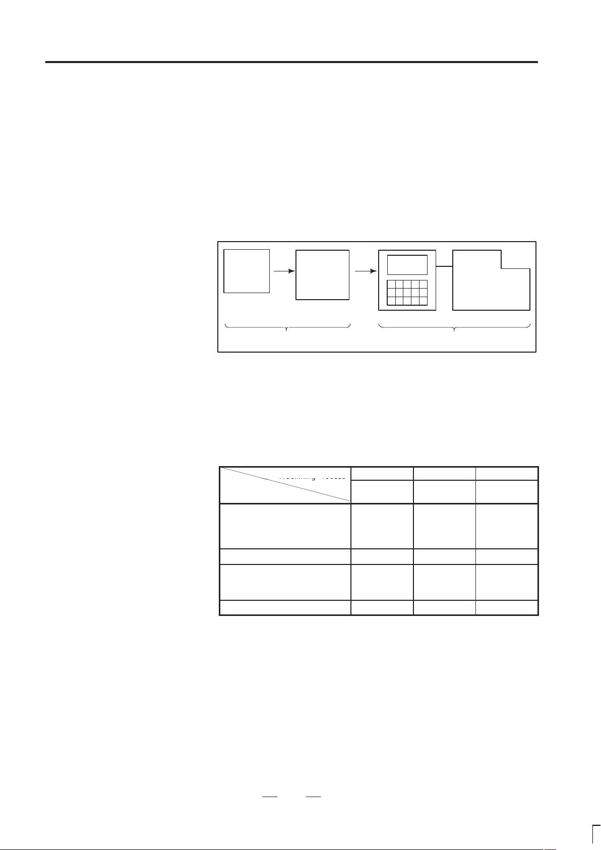
When machining the part using the CNC machine tool, first prepare the
program, then operate the CNC machine by using the program.
1) First, prepare the program from a part drawing to operate the CNC
machine tool.
How to prepare the program is described in the Chapter II.
PROGRAMMING.
2) The program is to be read into the CNC system. Then, mount the
workpieces and tools on the machine, and operate the tools according
to the programming. Finally, execute the machining actually.
How to operate the CNC system is described in the Chapter III.
OPERATION.
Part
drawing
CHAPTER II PROGRAMMING CHAPTER III OPERATION
Part
programming
CNC
MACHINE TOOL
Before the actual programming, make the machining plan for how to
machine the part.
Machining plan
1. Determination of workpieces machining range
2. Method of mounting workpieces on the machine tool
3. Machining sequence in every machining process
4. Machining tools and machining
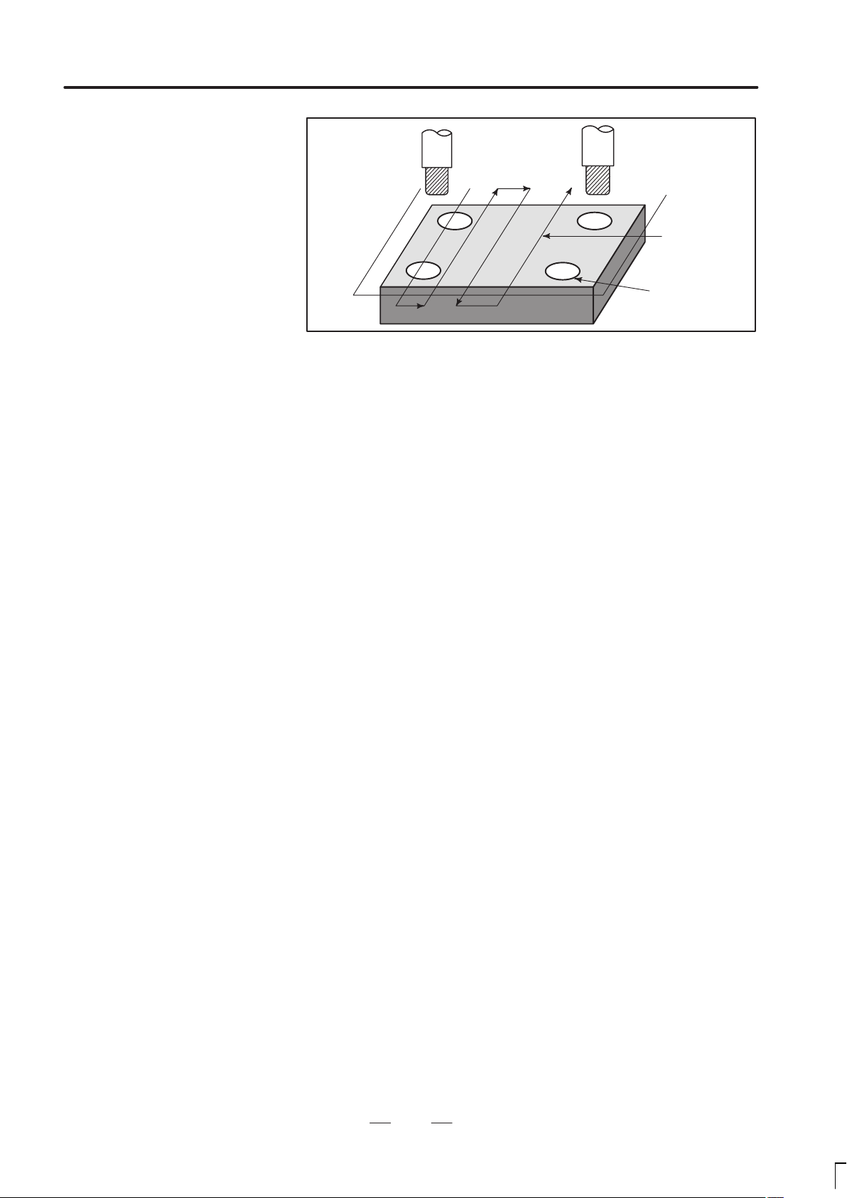
Decide the machining method in every machining process.
Machining process
Machining procedure
1. Machining method
: Rough
Semi
Finish
2. Machining tools
3. Machining conditions
: Feedrate
Cutting depth
4. Tool path
1 2 3
Feed cutting Side cutting
Hole
machining
5
Page 17
1. GENERAL
GENERAL
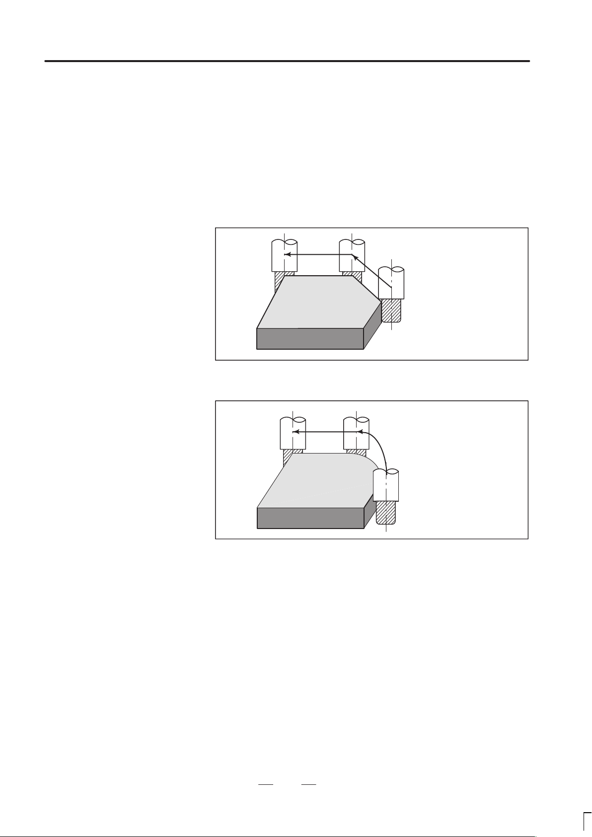
Tool
Side cutting
B–62454E/04
Face cutting
Hole machining
Prepare the program of the tool path and machining condition
according to the workpiece figure, for each machining.
6
Page 18

B–62454E/04
GENERAL
1. GENERAL
1.2
NOTES ON READING THIS MANUAL
1) The function of an CNC machine tool system depends not only on the
CNC, but on the combination of the machine tool, its magnetic
cabinet, the servo system, the CNC, the operator’s panels, etc. It is too
difficult to describe the function, programming, and operation relating
to all combinations. This manual generally describes these from the
stand–point of the CNC. So, for details on a particular CNC machine
tool, refer to the manual issued by the machine tool builder, which
should take precedence over this manual.
2) Headings are placed in the left margin so that the reader can easily
access necessary information. When locating the necessary
information, the reader can save time by searching though these
headings.
Machining programs, parameters, variables, etc. are stored in the CNC unit
internal non–volatile memory . In general, these contents are not lost by the
switching ON/OFF of the power. However , it is possible that a state can occur
where precious data stored in the non–volatile memory has to be deleted,
because of deletions from a maloperation, or by a failure restoration. In order
to restore rapidly when this kind of mishap occurs, it is recommended that
you create a copy of the various kinds of data beforehand.
This manual describes as many reasonable variations in equipment usage
as possible. It cannot address every combination of features, options and
commands that should not be attempted.
If a particular combination of operations is not described, it should not be attempted.
7
Page 19

PROGRAMMING
Page 20

B–62454E/04
1
PROGRAMMING
1. GENERAL
11
Page 21
1. GENERAL
PROGRAMMING
B–62454E/04
1.1
TOOL MOVEMENT
ALONG WORKPIECE
PARTS FIGURE–
INTERPOLATION
Explanations
Tool movement along a
straight line
The tool moves along straight lines and arcs constituting the workpiece
parts figure (See II–4).
The function of moving the tool along straight lines and arcs is called the
interpolation.
Tool
Workpiece
Fig.1.1 (a) Tool movement along a straight line
Program
G01 X_ _ Y_ _ ;
X_ _ ;
Tool movement along an
arc
Program
G03X_ _Y_ _R_ _;
Tool
Workpiece
Fig. 1.1 (b) Tool movement along an arc
12
Page 22
B–62454E/04
PROGRAMMING
1. GENERAL
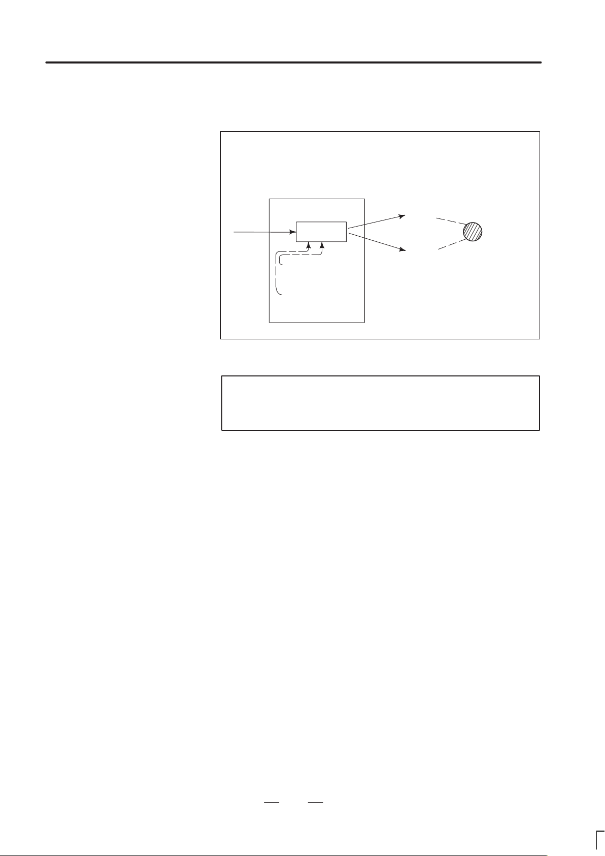
Symbols of the programmed commands G01, G02, ... are called the
preparatory function and specify the type of interpolation conducted in
the control unit.
(a) Movement along straight line
G01 Y_ _;
X– –Y– – – –;
Control unit
Interpolation
a)Movement
along straight
line
b)Movement
along arc
Fig. 1.1 (c) Interpolation function
(b) Movement along arc
G03X––Y––R––;
X axis
Y axis
Tool
movement
Notes
Some machines move tables instead of tools but this
manual assumes that tools are moved against workpieces.
13
Page 23

1. GENERAL
PROGRAMMING
B–62454E/04
1.2
FEED–
FEED FUNCTION
Movement of the tool at a specified speed for cutting a workpiece is called
the feed.
mm/min
F
Workpiece
Table
Fig. 1.2 (a) Feed function
Tool
Feedrates can be specified by using actual numerics. For example, to feed
the tool at a rate of 150 mm/min, specify the following in the program:
F150.0
The function of deciding the feed rate is called the feed function (See
II–5).
14
Page 24
B–62454E/04
1.3
PART DRAWING AND
TOOL MOVEMENT
PROGRAMMING
1. GENERAL
1.3.1
Reference Position
(Machine–Specific
Position)
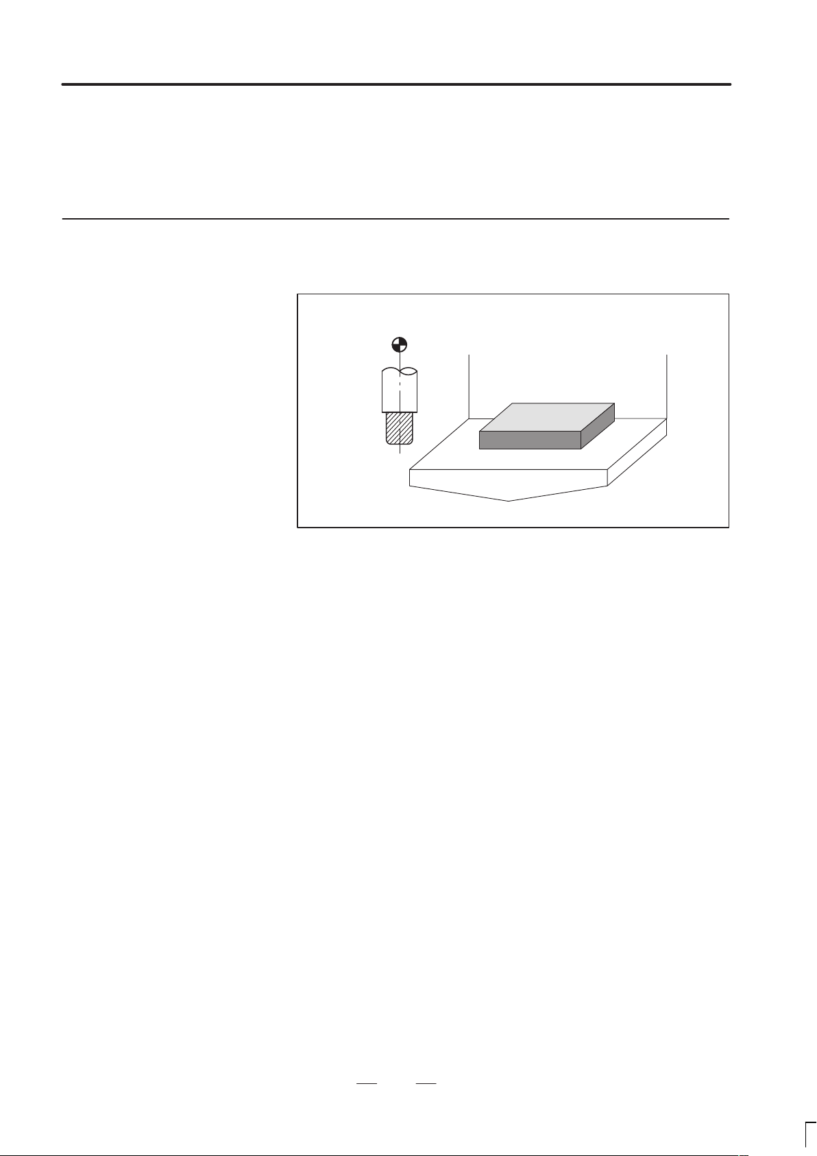
Explanations
A CNC machine tool is provided with a fixed position. Normally, tool
change and programming of absolute zero point as described later are
performed at this position. This position is called the reference position.
Reference position
Tool
Workpiece
Table
Fig. 1.3 (a) Reference position
The tool can be moved to the reference position in two ways:
(1)Manual reference position return (See III–3.1)
Reference position return is performed by manual button operation.
(2)Automatic reference position return (See II–6)
In general, manual reference position return is performed first after the
power is turned on. In order to move the tool to the reference position
for tool change thereafter, the function of automatic reference position
return is used.
15
Page 25
1. GENERAL
1.3.2
Coordinate System on
Part Drawing and
Coordinate System
Specified by CNC –
Coordinate System
PROGRAMMING
Z
B–62454E/04
Z
Y
Program
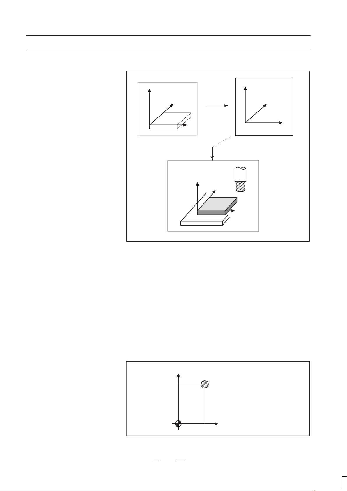
Explanations
Coordinate system
Part drawing
X
Z
Machine tool
Fig. 1.3.2 (a)
Coordinate system
CNC
Command
Tool
Y
Workpiece
X
Coordinate system
The following two coordinate systems are specified at different locations:
(See II–8)
(1)Coordinate system on part drawing
The coordinate system is written on the part drawing. As the program
data, the coordinate values on this coordinate system are used.
(2)Coordinate system specified by the CNC
The coordinate system is prepared on the actual machine tool table.
This can be achieved by programming the distance from the current
position of the tool to the zero point of the coordinate system to be set.
Y
230
30
Program
zero point
Fig. 1.3.2 (b) Coordinate system specified by the CNC
0
16
Present tool position
Distance to the zero point of a coordinate system to be set
X
Page 26
B–62454E/04
PROGRAMMING
1. GENERAL
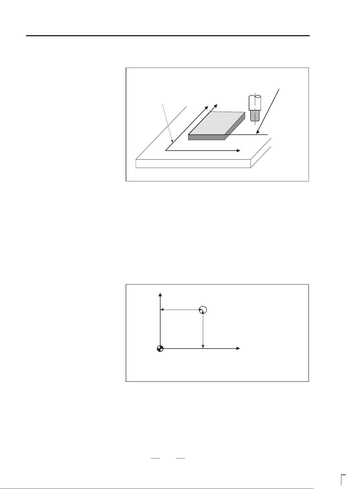
The positional relation between these two coordinate systems is
determined when a workpiece is set on the table.
Coordinate system on
part drawing established on the work-
Coordinate system specified by the CNC established on the table
Table
Fig. 1.3.2 (c) Coordinate system specified by CNC and coordinate
systemon part drawing
Y
Y
Workpiece
piece
X
X
Methods of setting the
two coordinate systems
in the same position
The tool moves on the coordinate system specified by the CNC in
accordance with the command program generated with respect to the
coordinate system on the part drawing, and cuts a workpiece into a shape
on the drawing.
Therefore, in order to correctly cut the workpiece as specified on the
drawing, the two coordinate systems must be set at the same position.
To set the two coordinate systems at the same position, simple methods
shall be used according to workpiece shape, the number of machinings.
(1) Using a standard plane and point of the workpiece.
Y
Fixed distance
Program
zero point
Bring the tool center to the workpiece standard point.
And set the coordinate system specified by CNC at this position.
Workpiece’s
standard point
Fixed distance
X
17
Page 27
1. GENERAL
PROGRAMMING
B–62454E/04
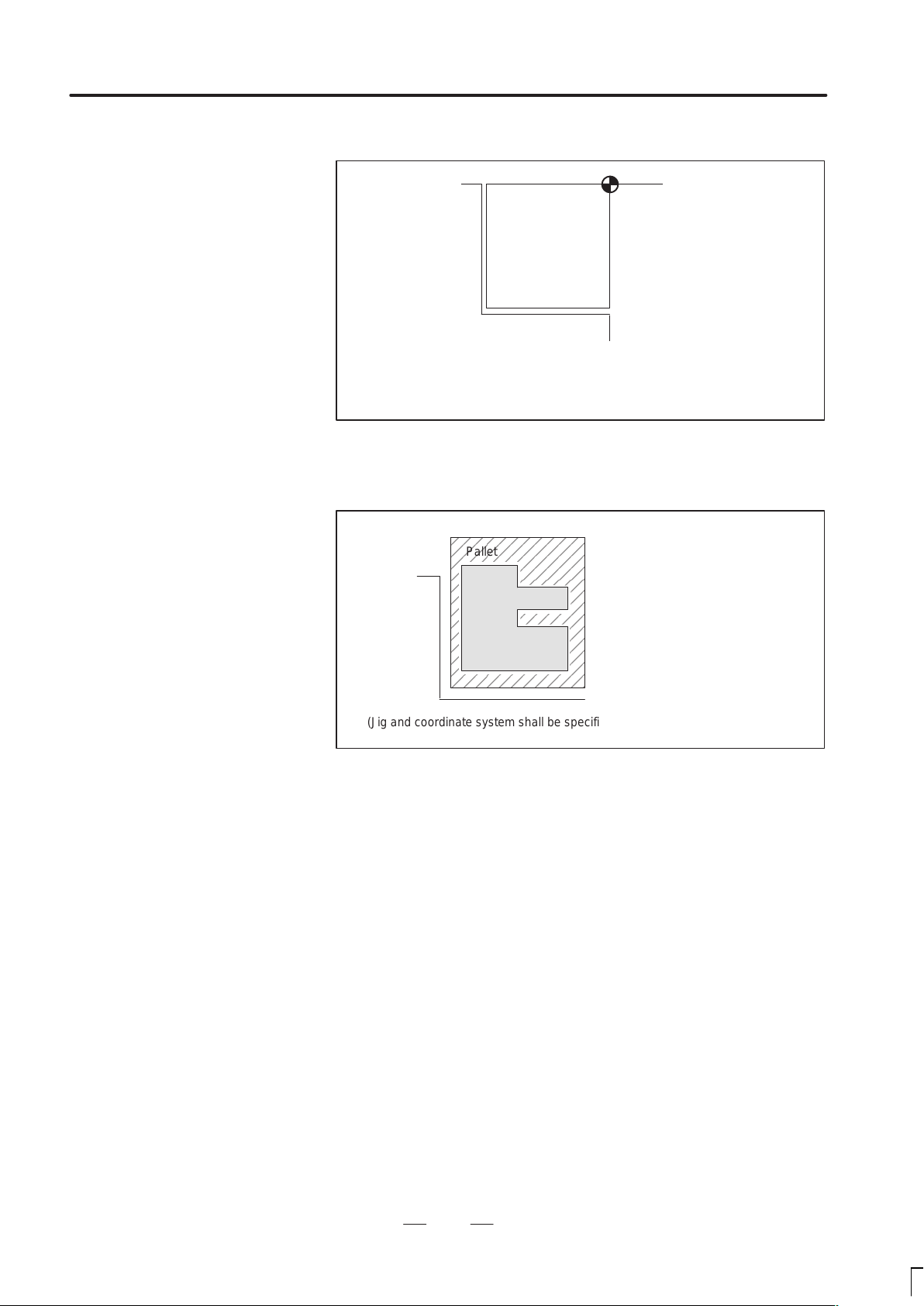
(2) Mounting a workpiece directly against the jig
Program zero point
Jig
Meet the tool center to the reference position. And set the coordinate system
specified by CNC at this position. (Jig shall be mounted on the predetermined
point from the reference position.)
(3) Mounting a workpiece on a pallet, then mounting the workpiece and
pallet on the jig
Pallet
Jig
Workpiece
(Jig and coordinate system shall be specified by the same as (2)).
18
Page 28
B–62454E/04
1.3.3
How to Indicate
Command Dimensions
for Moving the Tool –
Absolute, Incremental
Commands
PROGRAMMING
1. GENERAL
Explanations
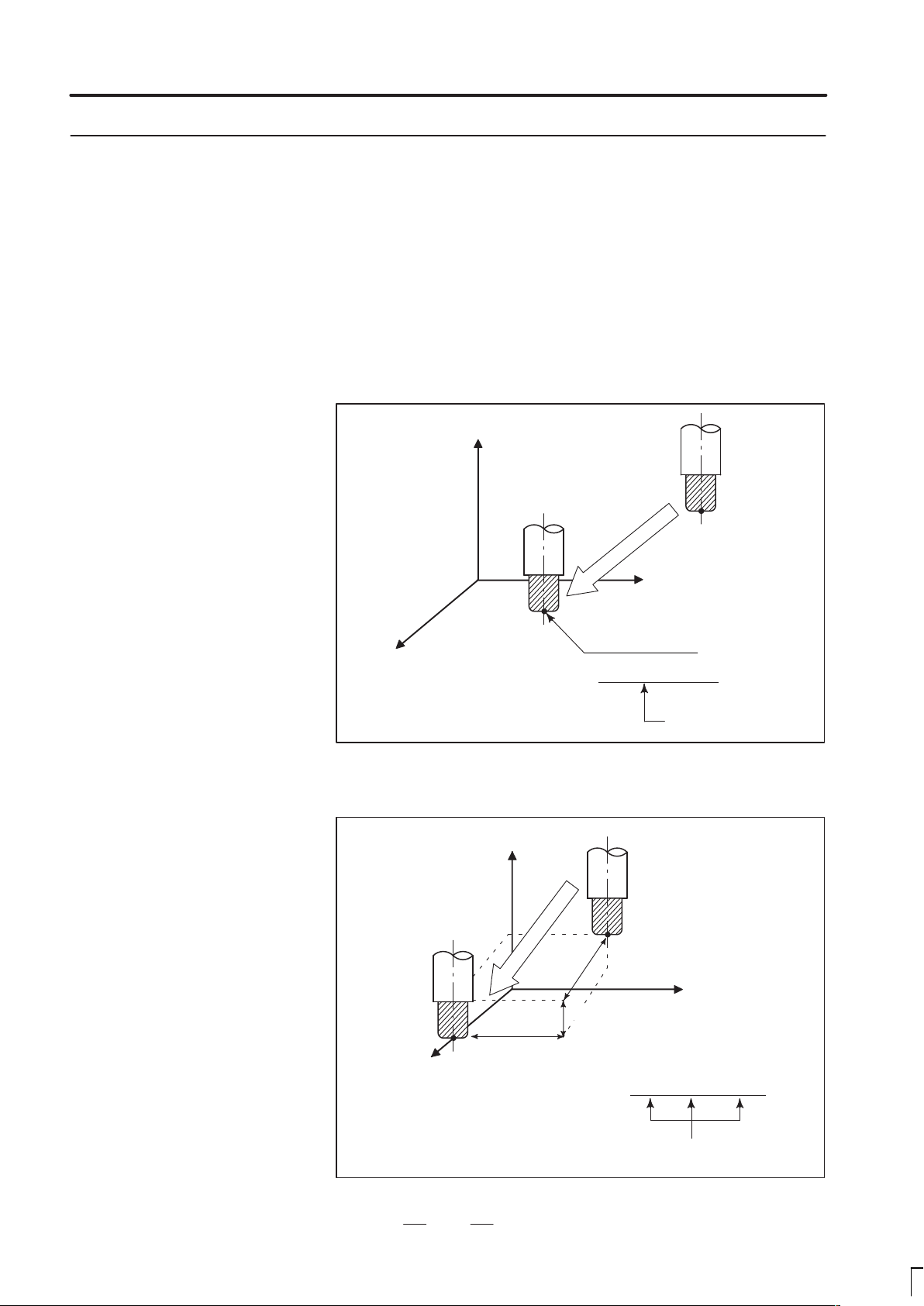
Absolute command
Command for moving the tool can be indicated by absolute command or
incremental command (See II–9.1).
The tool moves to a point at ”the distance from zero point of the
coordinate system” that is to the position of the coordinate values.
Z
X
Command specifying movement from
point A to point B
B(10.0,30.0,20.0)
G90 X10.0 Y30.0 Z20.0 ;
Coordinates of point B
Tool
A
Incremental command
Specify the distance from the previous tool position to the next tool
position.
Z
Tool
A
X=40.0
Z=–10.0
B
X
Command specifying movement from
point A to point B
19
Y=–30.0
G91 X40.0 Y–30.0 Z–10.0
Distance and direction for
movement along each axis
;
Page 29
1. GENERAL
PROGRAMMING
B–62454E/04
1.4
CUTTING SPEED –
SPINDLE SPEED
FUNCTION
Examples
The speed of the tool with respect to the workpiece when the workpiece
is cut is called the cutting speed.
As for the CNC, the cutting speed can be specified by the spindle speed
in rpm unit.
Tool
Spindle speed N
rpm
Workpiece
Tool diameter
φD mm
V: Cutting speed
m/min
<When a workpiece should be machined with a tool 100 mm in
diameter at a cutting speed of 80 m/min. >
The spindle speed is approximately 250 rpm, which is obtained from
N=1000v/πD. Hence the following command is required:
S250;
Commands related to the spindle speed are called the spindle speed
function ( See II–10) .
20
Page 30

B–62454E/04
PROGRAMMING
1. GENERAL
1.5
SELECTION OF TOOL
USED FOR VARIOUS
MACHINING – TOOL
FUNCTION
Examples
When drilling, tapping, boring, milling or the like, is performed, it is
necessary to select a suitable tool. When a number is assigned to each tool
and the number is specified in the program, the corresponding tool is
selected.
Tool number
01
02
A TC magazine
<When No.01 is assigned to a drilling tool>
When the tool is stored at location 01 in the ATC magazine, the tool
can be selected by specifying T01. This is called the tool function (See
II–11).
21
Page 31

1. GENERAL
PROGRAMMING
B–62454E/04
1.6
COMMAND FOR
MACHINE
OPERATIONS –
MISCELLANEOUS
FUNCTION
When machining is actually started, it is necessary to rotate the spindle,
and feed coolant. For this purpose, on–off operations of spindle motor and
coolant valve should be controlled (See II–12).
Tool
Coolant
Workpiece
The function of specifying the on–off operations of the components of the
machine is called the miscellaneous function. In general, the function is
specified by an M code.
For example, when M03 is specified, the spindle is rotated clockwise at
the specified spindle speed.
22
Page 32

B–62454E/04
PROGRAMMING
1. GENERAL
1.7
PROGRAM CONFIGURATION
A group of commands given to the CNC for operating the machine is
called the program. By specifying the commands, the tool is moved along
a straight line or an arc, or the spindle motor is turned on and off.
In the program, specify the commands in the sequence of actual tool
movements.
Block
Block
Tool movement sequence
Block
Program
Fig. 1.7 (a) Program configuration
Block
⋅
⋅
⋅
⋅
Block
A group of commands at each step of the sequence is called the block.
The program consists of a group of blocks for a series of machining. The
number for discriminating each block is called the sequence number, and
the number for discriminating each program is called the program
number (See II–13).
23
Page 33

1. GENERAL
PROGRAMMING
B–62454E/04
Explanations
D Block
D Program
The block and the program have the following configurations.
1 block
N ffff G ff Xff.f Yfff.f M ff S ff T ff ;
Sequence
number
Preparatory
function
Dimension word Miscel-
laneous
function
Fig. 1.7 (b) Block configuration
Spindle
function
Tool
function
End of
block
A block starts with a sequence number to identify the block and ends with
an end–of–block code.
This manual indicates the end–of–block code by ; (LF in the ISO code and
CR in the EIA code).
;
Offff;
⋅
⋅
⋅
M30 ;
Fig. 1.7 (c) Program configuration
Program number
Bloc
k
Bloc
k
⋅
Bloc
⋅
k
⋅
End of program
Normally , a program number is specified after the end–of–block (;) code
at the beginning of the program, and a program end code (M02 or M30)
is specified at the end of the program.
24
Page 34

B–62454E/04
PROGRAMMING
1. GENERAL
Main program and
subprogram
When machining of the same pattern appears at many portions of a
program, a program for the pattern is created. This is called the
subprogram. On the other hand, the original program is called the main
program. When a subprogram execution command appears during
execution of the main program, commands of the subprogram are
executed. When execution of the subprogram is finished, the sequence
returns to the main program.
Main program
⋅
⋅
M98P1001
⋅
⋅
⋅
M98P1002
⋅
⋅
⋅
M98P1001
⋅
⋅
Subprogram #1
O1001
M99
Subprogram #2
O1002
Program for
hole #1
Program for
hole #2
⋅
M99
Hole #1
Hole #1
Hole #2
Hole #2
25
Page 35

1. GENERAL
1.8
TOOL FIGURE AND TOOL MOTION BY PROGRAM
Explanations
PROGRAMMING
B–62454E/04
Machining using the end
of cutter – Tool length
compensation function
(See II–15.1)
Machining using the side
of cutter – Cutter
compensation function
(See II–15.4,15.5,15.6)
Usually, several tools are used for machining one workpiece. The tools
have different tool length. It is very troublesome to change the program
in accordance with the tools.
Therefore, the length of each tool used should be measured in advance.
By setting the difference between the length of the standard tool and the
length of each tool in the CNC (data display and setting : see III–11),
machining can be performed without altering the program even when the
tool is changed. This function is called tool length compensation.
Standard
tool
H1
H2
Workpiece
H3 H4
Because a cutter has a radius, the center of the cutter path goes around the
workpiece with the cutter radius deviated.
Cutter path using cutter
compensation
Machined part
figure
Workpiece
Cutter
If radius of cutters are stored in the CNC (Data Display and Setting : see
III–11), the tool can be moved by cutter radius apart from the machining
part figure. This function is called cutter compensation.
26
Page 36

B–62454E/04
PROGRAMMING
1. GENERAL
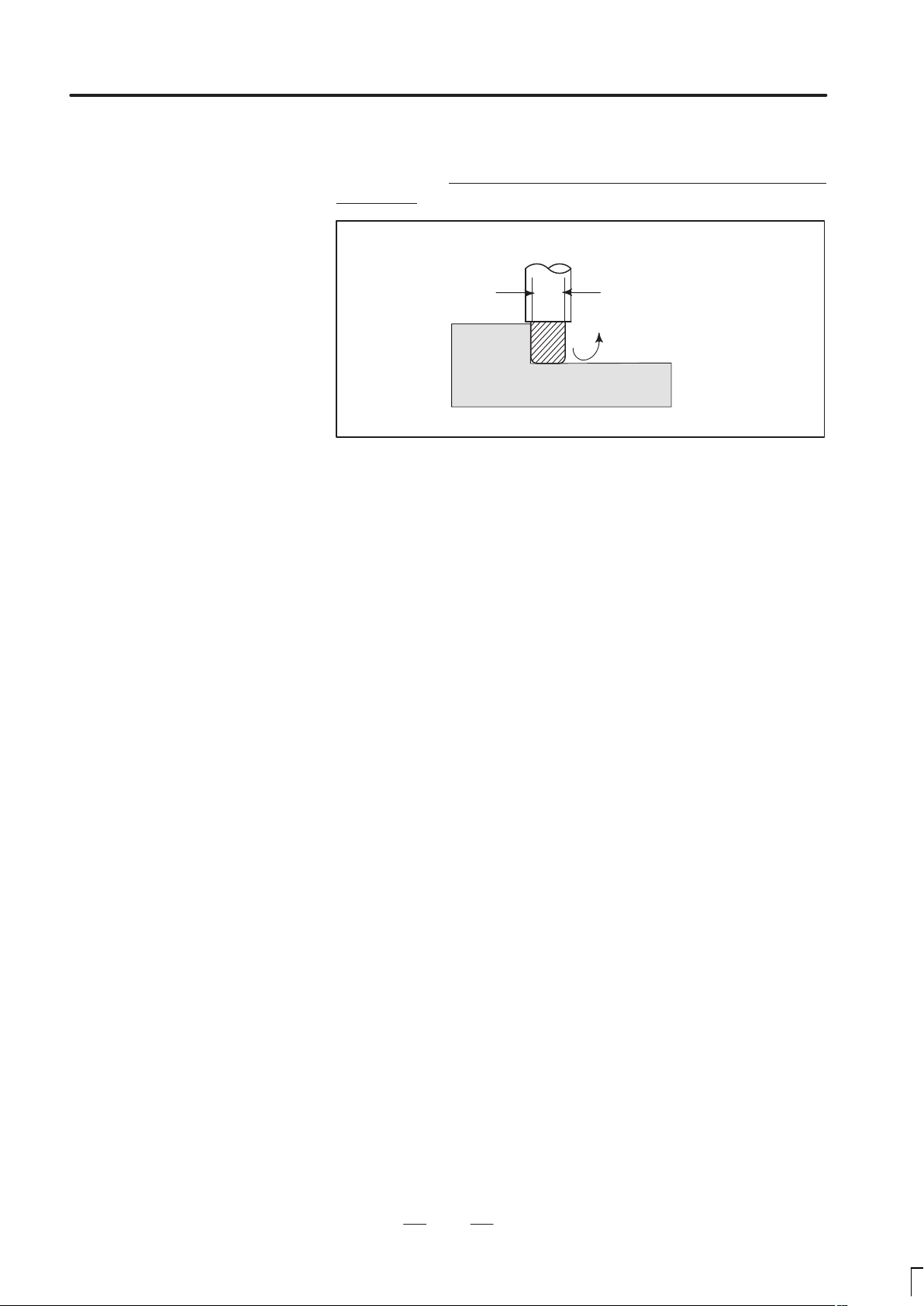
1.9
TOOL MOVEMENT
RANGE – STROKE
Limit switches are installed at the ends of each axis on the machine to
prevent tools from moving beyond the ends. The range in which tools can
move is called the stroke.
Table
Motor
Limit switch
Machine zero point
Specify these distances.
Tools cannot enter this area. The area is specified by data in memory or
a program.
Besides strokes defined with limit switches, the operator can define an
area which the tool cannot enter using a program or data in memory (see
Section III–11). This function is called stroke check.
27
Page 37

2. CONTROLED AXES
CONTROLLED AXES
2
PROGRAMMING
B–62454E/04
28
Page 38

B–62454E/04
2.1
CONTROLLED AXES
PROGRAMMING
2. CONTORLED AXES
Series 16, Series 160
Series 18, Series 180
Item
No. of basic controlled
axes
Controlled axes
expansion (total)
Basic simultaneously
controlled axes
Simultaneously controlled
axes expansion (total)
16–MB
160–MB
3 axes
Max. 8 axes
(included in Cs axis)
2 axes
Max. 6 axes Max. 6 axes for each path
16–MB, 160–MB
(two–path control)
3 axes for each path
(6 axes in total)
Max. 7 axes
(Feed 6 axes + Cs axis)
2 axes for each path
(4 axes in total)
Note
The number of simultaneously controllable axes for manual
operation jog feed, manual reference position return, or
manual rapid traverse) is 1 or 3 (1 when bit 0 (JAX) of
parameter 1002 is set to 0 and 3 when it is set to 1).
Item 18–MB, 180–MB
No. of basic controlled axes 3 axes
Controlled axes expansion (total)
Basic simultaneously controlled axes 2 axes
Simultaneously controlled axes expansion (total) Max. 4 axes
Max. 6 axes
(included in Cs axis)
2.2
AXIS NAME
Note
The number of simultaneously controllable axes for manual
operation jog feed, manual reference position return, or
manual rapid traverse) is 1 or 3 (1 when bit 0 (JAX) of
parameter 1002 is set to 0 and 3 when it is set to 1).
The user can assign any one of the following nine characters as the axis
name: A, B, C, U, V, W, X, Y, and Z.Parameter No. 1020 is used to
determine the name of each axis.
When this parameter is set to 0 or a character other than the valid
characters is specified, an axis name from 1 to 8 is assigned by default.
In two–path control, the basic three axis names are fixed to X, Y, and Z
for either path, but the name of an additional axis can be selected from A,
B, C, U, V, and W by parameter 1020. Duplicate axis names cannot be
used in the same path, but the same axis name can be used in different
paths.
29
Page 39

2. CONTROLED AXES
Limitations
PROGRAMMING
B–62454E/04
Default axis name
Duplicate axis names
When a default axis name (1 to 8) is used, operation in the MEM mode
and MDI mode is disabled.
If a duplicate axis name is specified in the parameter, operation is enabled
only for the axis specified first.
Notes
In two–path control, axis information displayed on the CRT
screen, such as the current position, may contain an axis
name with a suffix indicating the related path (X1, X2, etc).
This is intended to provide a comprehensible indication of
the path to which the axis belongs. The suffix cannot be
used in a program ; the axis name should be specified as X,
Y, Z, U, V, W, A, B, or C.
30
Page 40

B–62454E/04
PROGRAMMING
2. CONTORLED AXES
2.3
INCREMENT SYSTEM
The increment system consists of the least input increment (for input) and
least command increment (for output). The least input increment is the
least increment for programming the travel distance. The least command
increment is the least increment for moving the tool on the machine. Both
increments are represented in mm, inches, or deg.
Name of increment system
IS–B
Name of increment system
IS–C
Least input increment
0.001mm
0.0001inch
0.001deg
Least input incre-
ment
0.0001mm
0.00001inch
0.00001deg
Least command
increment
0.001mm
0.0001inch
0.001deg
Least command
increment
0.0001mm
0.00001inch
0.00001deg
Maximum
stroke
99999.999mm
9999.9999inch
99999.999deg
Maximum
stroke
9999.9999mm
999.99999inch
9999.9999deg
The least command increment is either metric or inch depending on the
machine tool. Set metric or inch to the parameter INM (No.100#0).
For selection between metric and inch for the least input increment, G
code (G20 or G21) or a setting parameter selects it.
Combined use of the inch system and the metric system is not allowed.
There are functions that cannot be used between axes with different unit
systems (circular interpolation, cutter compensation, etc.). For the
increment system, see the machine tool builder’s manual.
31
Page 41

2. CONTROLED AXES
IS–B
IS–C
PROGRAMMING
B–62454E/04
2.4
MAXIMUM STROKE
Maximum stroke = Least command increment 99999999
See 2.3 Incremen System.
Table 2.4(a) Maximum strokes
Increment system Maximum stroke
Metric machine system 99999.999 mm
99999.999 deg
–
Inch machine system 9999.9999 inch
99999.999 deg
Metric machine system 9999.9999 mm
9999.9999 deg
–
Inch machine system 999.99999 inch
9999.9999 deg
Notes
1 A command exceeding the maximum stroke cannot be
specified.
2 The actual stroke depends on the machine tool.
32
Page 42

B–62454E/04
3
3. PREP ARATORY FUNCTION
PROGRAMMING
PREPARATORY FUNCTION (G FUNCTION)
A number following address G determines the meaning of the command
for the concerned block.
G codes are divided into the following two types.
Type Meaning
One–shot G code The G code is effective only in the block in which it is
specified.
Modal G code The G code is effective until another G code of the
same group is specified.
(Example )
G01 and G00 are modal G codes in group 01.
(G FUNCTION)
G01X ;
Z;
X;
G00Z
G01 is effective in this range.
;
33
Page 43

3. PREP ARATORY FUNCTION
(G FUNCTION)
PROGRAMMING
B–62454E/04
Explanations
1. When the clear state (bit 6 (CLR) of parameter No. 3402) is set at
power–up or reset, the modal G codes are placed in the states
described below.
(1) The modal G codes are placed in the states marked with
as
indicated in Table 3.
(2) G20 and G21 remain unchanged when the clear state is set at
power–up or reset.
(3) Which status G22 or G23 at power on is set by parameter G23 (No.
3402#7). However, G22 and G23 remain unchanged when the
clear state is set at reset.
(4) The user can select G00 or G01 by setting bit 0 (G01) of parameter
No. 3402.
(5) The user can select G90 or G91 by setting bit 3 (G91) of parameter
No. 3402.
(6) The user can select G17, G18, or G19 by setting bit 1 (parameterG18)
and bit 2 (parameter G19) of parameter No. 3402.
2.G codes other than G10 and G11 are one–shot G codes.
3.When a G code not listed in the G code list is specified, or a G code
that has no corresponding option is specified, P/S alarm No. 010 is
output.
4.Multiple G codes can be specified in the same block if each G code
belongs to a different group. If multiple G codes that belong to the
same group are specified in the same block, only the last G code
specified is valid.
5.If a G code belonging to group 01 is specified in a canned cycle, the
canned cycle is cancelled. This means that the same state set by
specifying G80 is set. Note that the G codes in group 01 are not
affected by a G code specifying a canned cycle.
6.G codes are indicated by group.
34
Page 44

B–62454E/04
01
00
25
17
06
04
24
00
3. PREP ARATORY FUNCTION
PROGRAMMING
Table 3 G code list (1/3)
G code
G00
G01
G02
G03 Circular interpolation/Helical interpolation CCW
G04 Dwell, Exact stop
G05 High speed cycle machining
G07.1 (G107) Cylindrical interpolation
G08
G09
G10 Programmable data input
G10.6 Tool retract & recover
G11 Programmable data input mode cancel
G12.1
G13.1
G15
G16
G17
G18
G19
G20
G21
G22
G23
G25
G26
G27 Reference position return check
G28 Return to reference position
G29
G30
G30.1 Floating reference point return
G31 Skip function
G33 01 Thread cutting
Group Function
Positioning
02 ZpXp plane selection Yp: Y axis or its parallel axis
Linear interpolation
Circular interpolation/Helical interpolation CW
Look–ahead control
Exact stop
Polar coordinate interpolation mode
Polar coordinate interpolation cancel mode
Polar coordinates command cancel
Polar coordinates command
XpY p plane selection Xp: X axis or its parallel axis
Y pZp plane selection Zp: Z axis or its parallel axis
Input in inch
Input in mm
Stored stroke check function on
Stored stroke check function off
Spindle speed fluctuation detection off
Spindle speed fluctuation detection on
Return from reference position
2nd, 3rd and 4th reference position return
(G FUNCTION)
35
Page 45

3. PREP ARATORY FUNCTION
00
08
00
11
22
00
15
(G FUNCTION)
G code
G37
G39
G40
G41
G42 Cutter compensation right
G40.1 (G150)
G41.1 (G151) 19 Normal direction control left side on
G42.1 (G152) Normal direction control right side on
G43
G44
G45 Tool offset increase
G46
G47
G48 Tool offset double decrease
G49
G50
G51
G50.1
G51.1
G52
G53
G54
G54.1 Additional workpiece coordinate system selection
G55
G56
G57 Workpiece coordinate system 4 selection
G58 Workpiece coordinate system 5 selection
G59 Workpiece coordinate system 6 selection
G60 00 Single direction positioning
G61 Exact stop mode
G62
G63
G64
PROGRAMMING
Table 3 G code list (2/3)
Group Function
Automatic tool length measurment
Corner offset circular interpolation
Cutter compensation cancel
07
08 Tool length compensation cancel
14
Cutter compensation left
Normal direction control cancel mode
Tool length compensation + direction
Tool length compensation – direction
Tool offset decrease
Tool offset double increase
Scaling cancel
Scaling
Programmable mirror image cancel
Programmable mirror image
Local coordinate system setting
Machine coordinate system selection
Workpiece coordinate system 1 selection
Workpiece coordinate system 2 selection
Workpiece coordinate system 3 selection
Automatic corner override
Tapping mode
Cutting mode
B–62454E/04
36
Page 46

B–62454E/04
12
16
09
03
05
13
10
20
3. PREP ARATORY FUNCTION
PROGRAMMING
Table 3 G code list (3/3)
G code
G65 00 Macro call
G66
G67
G68
G69
G73
G74
G75 01 Plunge grinding cycle (for grinding machine)
G76
G77 Direct constant–dimension plunge grinding cycle(for grinding machine)
G78 01 Continuous–feed surface grinding cycle(for grinding machine)
G79 Intermittent–feed surface grinding cycle(for grinding machine)
G80
G81
G82 Drilling cycle or counter boring cycle
G83 Peck drilling cycle
G84
G85 Boring cycle
G86 Boring cycle
G87 Back boring cycle
G88 Boring cycle
G89 Boring cycle
G90
G91
G92 00 Setting for work coordinate system or clamp at maximum spindle speed
G94
G95
G96
G97
G98
G99
G160
G161
Group Function
Macro modal call
Macro modal call cancel
Coordinate rotation
Coordinate rotation cancel
Peck drilling cycle
Counter tapping cycle
09
09
Fine boring cycle
Canned cycle cancel/external operation function cancel
Drilling cycle, spot boring cycle or external operation function
Tapping cycle
Absolute command
Increment command
Feed per minute
Feed per rotation
Constant surface speed control
Constant surface speed control cancel
Return to initial point in canned cycle
Return to R point in canned cycle
In–feed control function cancel(for grinding machine)
In–feed control function(for grinding machine)
(G FUNCTION)
37
Page 47

4. INTERPOLA TION FUNCTIONS
INTERPOLATION FUNCTIONS
4
PROGRAMMING
B–62454E/04
38
Page 48

B–62454E/04
PROGRAMMING
4. INTERPOLA TION FUNCTIONS
4.1
POSITIONING (G00)
Format
Explanations
The G00 command moves a tool to the position in the workpiece system
specified with an absolute or an incremental command at a rapid traverse
rate.
In the absolute command, coordinate value of the end point is
programmed.
In the incremental command the distance the tool moves is programmed.
G00IP_;
IP_: For an absolute command, the coordinates of an end
position, and for an incremental commnad, the distance
the tool moves.
Either of the following tool paths can be selected according to bit 1 of
parameter LRP No. 1401.
Nonlinear interpolation positioning
The tool is positioned with the rapid traverse rate for each axis
separately. The tool path is normally straight.
Linear interpolation positioning
The tool path is the same as in linear interpolation (G01). The tool
is positioned within the shortest possible time at a speed that is not
more than the rapid traverse rate for each axis.
Start position
Linear interpolation positioning
End position
Non linear interpolation positioning
The rapid traverse rate in G00 command is set to the parameter No. 1420
for each axis independently by the machine tool builder. In the
posiitoning mode actuated by G00, the tool is accelerated to a
predetermined speed at the start of a block and is decelerated at the end
of a block. Execution proceeds to the next block after confirming the
in–position.
”In–position ” means that the feed motor is within the specified range.
This range is determined by the machine tool builder by setting to
parameter (No. 1826).
In–position check for each block can be disabled by setting bit 5 (NCI)
of parameter No.1601 accordingly.
39
Page 49

4. INTERPOLA TION FUNCTIONS
PROGRAMMING
B–62454E/04
Limitations
The rapid traverse rate cannot be specified in the address F.
Even if linear interpolation positioning is specified, nonlinear
interpolation positioning is used in the following cases. Therefore, be
careful to ensure that the tool does not foul the workpiece.
G28 specifying positioning between the reference and intermediate
positions.
G53
40
Page 50

B–62454E/04
PROGRAMMING
4. INTERPOLA TION FUNCTIONS
4.2
SINGLE DIRECTION POSITIONING (G60)
Format
For accurate positioning without play of the machine (backlash), final
positioning from one direction is available.
Overrun
Start position
Start position
End position
G60 IP_;
IP_ : For an absolute command, the coordinates of an end
position, and for an incremental commnad, the distance
the tool moves.
Temporary stop
Explanations
Examples
An overrun and a positioning direction are set by the parameter (No.
5440). Even when a commanded positioning direction coincides with
that set by the parameter, the tool stops once before the end point.
G60, which is an one–shot G–code, can be used as a modal G–code in
group 01 by setting 1 to the parameter (No. 5431 bit 0 MDL).
This setting can eliminate specifying a G60 command for every block.
Other specifications are the same as those for an one–shot
G60 command.
When an one–shot G code is sepcified in the single direction positioning
mode, the one–shot G command is effective like G codes in group 01.
When one–shot
G60 commands are used.
G90;
G60 X0Y0;
G60 X100;
G60 Y100;
G04 X10;
G00 X0Y0;
Single direction
positioning
When modal
G60 command is used.
G90G60;
X0Y0;
X100;
Y100;
G04X10;
G00X0Y0;
Single direction
positioning mode start
Single direction
positioning
Dwell
Single direction
positioning
mode cancel
41
Page 51

4. INTERPOLA TION FUNCTIONS
PROGRAMMING
B–62454E/04
Restrictions
During canned cycle for drilling, no single direction positioning is
effected in Z axis.
No single direction positioning is effected in an axis for which no
overrun has been set by the parameter.
When the move distance 0 is commanded, the single direction
positioning is not performed.
The direction set to the parameter is not effected by mirror image.
The single direction positioning does not apply to the shift motion in
the canned cycles of G76 and G87.
42
Page 52

B–62454E/04
PROGRAMMING
4. INTERPOLA TION FUNCTIONS
4.3
LINEAR
INTERPOLATION
(G01)
Format
Explanations
Tools can move along a line
G01 IP_F_;
IP_:For an absolute command, the coordinates of an end point ,
and for an incremental commnad, the distance the tool moves.
F_:Speed of tool feed (Feedrate)
A tools move along a line to the specified position at the feedrate
specified in F.
The feedrate specified in F is effective until a new value is specified. It
need not be specified for each block.
The feedrate commanded by the F code is measured along the tool path.
If the F code is not commanded, the feedrate is regarded as zero.
The feedrate of each axis direction is as follows.
G01ααββγγζζ
Feed rate of α axis direction :
Feed rate of Β axis direction :
Feed rate of Γ axis direction :
Feed rate of Ζ axis direction :
2
Ǹ
L +
) 2) 2)
Ff ;
F +
Ơ f
L
F+
Ơ f
L
F +
Ơ f
L
+
Ơ f
F
L
2
The feed rate of the rotary axis is commanded in the unit of deg/min (the
unit is decimal point position).
When the straight line axis α(such as X, Y, or Z) and the rotating axisβ
(such as A, B, or C) are linearly interpolated, the feed rate is that in which
the tangential feed rate in the αandβ cartesian coordinate system is
commanded by F(mm/min).
β–axis feedrate is obtained ; at first, the time required for distribution is
calculated by using the above fromula, then the β –axis feedrate unit is
changed to deg 1min.
43
Page 53

4. INTERPOLA TION FUNCTIONS
PROGRAMMING
B–62454E/04
A calcula;tion example is as follows.
G91 G01 X20.0B40.0 F300.0 ;
This changes the unit of the C axis from 40.0 deg to 40mm with metric
input. The time required for distribution is calculated as follows:
Examples
Linear interpolation
Ǹ
202) 40
The feed rate for the C axis is
300
40
0.14907
2
0.14907 (min)8
8
268.3 degńmin
In simultaneous 3 or 4 axes control, the feed rate is calculated the same
way as in 2 axes control.
(G91) G01X200.0Y100.0F200.0 ;
Y axis
100.0
(End position)
Feedrate for the
rotation axis
(Start position)
G91G01C–90.0 G300.0 ;Feed rate of 300deg/min
(End point)
200.00
(Start point)
90°
Feedrate is 300 deg/min
X axis
44
Page 54

B–62454E/04
PROGRAMMING
4. INTERPOLA TION FUNCTIONS
4.4
CIRCULAR
INTERPOLATION
(G02,G03)
Format
The command below will move a tool along a circular arc.
Arc in the XpYp plane
G17
Arc in the ZpXp plane
G18
Arc in the YpZp plane
G19
G02
G03
G02
G03
G02
G03
Xp_Yp_
Xp_ p_
Yp_ Zp_
I_ J_
R_
I_ K_
R_
J_ K_
R_
F_ ;
F_
F_
Table.4.4 Description of the Command Format
Command
G17 Specification of arc on XpYp plane
G18 Specification of arc on ZpXp plane
G19 Specification of arc on YpZp plane
G02 Circular Interpolation Clockwise direction (CW)
G03 Circular Interpolation Counterclockwise direction (CCW)
X
p_
Y
p_
Z
p_
I_ Xp axis distance from the start point to the center of an arc
J_ Yp axis distance from the start point to the center of an arc
Command values of X axis or its parallel axis
(set by parameter No. 1022)
Command values of Y axis or its parallel axis
(set by parameter No. 1022)
Command values of Z axis or its parallel axis
(set by parameter No. 1022)
with sign
with sign
Description
k_ Zp axis distance from the start point to the center of an arc
with sign
R_ Arc radius (with sign)
F_ Feedrate along the arc
45
Page 55

4. INTERPOLA TION FUNCTIONS
Explanations
PROGRAMMING
B–62454E/04
Direction of the circular
interpolation
Distance moved on an
arc
Distance from the start
point to the center of arc
”Clockwise”(G02) and ”counterclockwise”(G03) on the XpYp plane
(Z
plane or YpZp plane) are defined when the XpYp plane is viewed
pXp
in the positive–to–negative direction of the Z
axis (Yp axis or Xp axis,
p
respectively) in the Cartesian coordinate system. See the figure below.
Yp Xp Zp
G18
G03
Zp
G03
G02
Yp
G19
G02
G17
G03
G02
Xp
The end point of an arc is specified by address Xp, Yp or Zp, and is
expressed as an absolute or incremental value according to G90 or G91.
For the incremental value, the distance of the end point which is viewed
from the start point of the arc is specified.
The arc center is specified by addresses I, J, and K for the Xp, Y p, and Zp
axes, respectively . The numerical value following I, J, or K, however, is
a vector component in which the arc center is seen from the start point,
and is always specified as an incremental value irrespective of G90 and
G91, as shown below.
I, J, and K must be signed according to the direction.
End point (x,y)
yx
x
Center
i
Start
point
j
I0,J0, and K0 can be omitted. When Xp, Yp , and Z
End point (z,x)
z
k
Center
Start
point
End point (y ,z)
z
y
i
Center
p
j
are omitted (the end
Start
point
k
point is the same as the start point) and the center is specified with I, J,
and K, a 360° arc (circle) is specified.
G021; Command for a circle
If the difference between the radius at the start point and that at the
end point exceeds the permitted value in a parameter (No.3410), an P/S
alarm (No.020) occurs.
46
Page 56

B–62454E/04
PROGRAMMING
4. INTERPOLA TION FUNCTIONS
Arc radius
The distance between an arc and the center of a circle that contains the arc
can be specified using the radius, R, of the circle instead of I, J, and K.
In this case, one arc is less than 180°, and the other is more than 180° are
considered. When an arc exceeding 180° is commanded, the radius must
be specified with a negative value. If Xp, Yp, and Zp are all omitted, if
the end point is located at the same position as the start point and when
R is used, an arc of 0° is programmed
G02R ; (The cutter does not move.)
For arc (1)(less than 180°)
G91 G02 X
For arc (2)(greater than 180°)
G91 G02 X
60.0 YP20.0 R50.0 F300.0 ;
P
60.0 YP20.0 R–50.0 F300.0 ;
P
2
r=50mm
End point
1
Feedrate
Restrictions
Start point
r=50mm
Y
X
The feedrate in circular interpolation is equal to the feed rate specified by
the F code, and the feedrate along the arc (the tangential feedrate of the
arc) is controlled to be the specified feedrate.
The error between the specified feedrate and the actual tool feedrate is
±2% or less. However, this feed rate is measured along the arc after the
cutter compensation is applied
If I, J, K, and R addresses are specified simultaneously, the arc specified
by address R takes precedence and the other are ignored.
If an axis not comprising the specified plane is commanded, an alarm is
displayed.
For example, if axis U is specified as a parallel axis to X axis when plane
XY is specified, an P/S alarm (No.028)is displayed.
When an arc having a center angle approaching 180° is specified, the
calculated center coordinates may contain an error. In such a case, specify
the center of the arc with I, J, and K.
47
Page 57

4. INTERPOLA TION FUNCTIONS
PROGRAMMING
B–62454E/04
Examples
Y axis
100
50R
140
60R
200
60
40
0
90 120
The above tool path can be programmed as follows ;
G92X200.0 Y40.0 Z0 ;
G90 G03 X140.0 Y100.0R60.0 F300.;
G02 X120.0 Y60.0R50.0 ;
or
G92X200.0 Y40.0Z0 ;
G90 G03 X140.0 Y100.0I-60.0 F300.;
G02 X120.0 Y60.0I-50.0 ;
G91 G03 X-60.0 Y60.0 R60.0 F300.;
G02 X-20.0 Y-40.0 R50.0 ;
or
G91 G03 X-60.0 Y60.0 I-60.0 F300. ;
G02 X-20.0 Y-40.0 I-50.0 ;
X axis
48
Page 58

B–62454E/04
PROGRAMMING
4. INTERPOLA TION FUNCTIONS
4.5
HELICAL
INTERPOLATION
(G02,G03)
Format
Helical interpolation which moved helically is enabled by specifying up
to two other axes which move synchronously with the circular
interpolation by circular commands.
Synchronously with arc of XpYp plane
G18
G02
G03
G02
G03
G02
G03
XpYp
XpZp
YpZp
G17
Synchronously with arc of ZpXp plane
Synchronously with arc of YpZp plane
G19
α,β:Any one axis where circular interpolation is not applied
Up to two other axes can be specified.
IJ
R
IK
R
JK
R
α(β)F
αβ)F
α_(β_)F_;
.
Explanations
The command method is to simply or secondary add a move command
axis which is not circular interpolation axes. An F command specifies a
feed rate along a circular arc. Therefore, the feed rate of the linear axis
is as follows:
Length of linear axis
F×
Length of circular arc
Determine the feed rate so the linear axis feed rate does not exceed any
of the various limit values.Bit 0 (HFC) of parameter No. 1404 can be used
to prevent the linear axis feedrate from exceeding various limit values.
Z
Tool path
YX
Restrictions
The feedrate along the circumference of two circular interpolated axes is the specified feedrate.
⋅Cutter compensation is applied only for a circular arc.
⋅Tool offset and tool length compensation cannot be used in a block in
which a helical cutting is commanded.
49
Page 59

4. INTERPOLA TION FUNCTIONS
PROGRAMMING
B–62454E/04
4.6
POLAR
COORDINATE
INTERPOLATION
(G12.1,G13.1)
Format
Specify G12.1 and G13.1
in Separate Blocks.
Explanations
Polar coordinate
interpolation plane
Polar coordinate interpolation is a function that exercises contour control
in converting a command programmed in a Cartesian coordinate system
to the movement of a linear axis (movement of a tool) and the movement
of a rotary axis (rotation of a workpiece). This function is useful for
grinding a cam shaft.
G12.1 ;
G13.1 ;
Starts polar coordinate interpolation mode (enables polar
coordinate interpolation)
Specify linear or circular interpolation using coordinates in a
Cartesian coordinate system consisting of a linear axis and
rotary axis (virtual axis).
Polar coordinate interpolation mode is cancelled (for not
performing polar coordinate interpolation)
G12.1 starts the polar coordinate interpolation mode and selects a polar
coordinate interpolation plane (Fig. 4.6 (a)). Polar coordinate
interpolation is performed on this plane.
Rotary axis (virtual axis)
(unit:mm or inch)
Linear axis
(unit:mm or inch)
Origin of the local coordinate system (G52 command)
(Or origin of the workpiece coordinate system)
Fig4.6 (a) Polar coordinate interpolation plane.
When the power is turned on or the system is reset, polar coordinate
interpolation is canceled (G13.1).
The linear and rotation axes for polar coordinate interpolation must be set
in parameters (No. 5460 and 5461) beforehand.
Notes
The plane used before G12.1 is specified (plane selected by
G17, G18, or G19) is canceled. It is restored when G13.1
(canceling polar coordinate interpolation) is specified.
When the system is reset, polar coordinate interpolation is
canceled and the plane specified by G17, G18, or G19 is
used.
50
Page 60

B–62454E/04
PROGRAMMING
4. INTERPOLA TION FUNCTIONS
Distance moved and
feedrate for polar
coordinate interpolation
The unit for coordinates
on the hypothetical axis is
the same as the unit for
the linear axis (mm/inch)
The unit for the feedrate
is mm/min or inch/min
G codes which can be
specified in the polar
coordinate interpolation
mode
In the polar coordinate interpolation mode, program commands are
specified with Cartesian coordinates on the polar coordinate interpolation
plane. The axis address for the rotation axis is used as the axis address
for the second axis (virtual axis) in the plane. Whether a diameter or
radius is specified for the first axis in the plane is the same as for the
rotation axis regardless of the specification for the first axis in the plane.
The virtual axis is at coordinate 0 immediately after G12.1 is specified.
Polar interpolation is started assuming the angle of 0 for the position of
the tool when G12.1 is specified.
Specify the feedrate as a speed (relative speed between the workpiece and
tool) tangential to the polar coordinate interpolation plane (Cartesian
coordinate system) using F.
G01 Linear interpolation
G02, G03 Circular interpolation
G04 Dwell, Exact stop
G40, G41, G42 Cutter compensation
(Polar coordinate interpolation is applied to the
path after cutter compensation.)
G65, G66, G67 Custom macro command
G90, G91 Absolute command, incremental command
G94, G95 Feed per minute, feed per revolution
Circular interpolation in
the polar coordinate
plane
Movement along axes
not in the polar
coordinate interpolation
plane in the polar
coordinate interpolation
mode
Current position display
in the polar coordinate
interpolation mode
The addresses for specifying the radius of an arc for circular interpolation
(G02 or G03) in the polar coordinate interpolation plane depend on the
first axis in the plane (linear axis).
⋅I and J in the Xp–Yp plane when the linear axis is the X–axis or an axis
parallel to the X–axis.
⋅J and K in the Yp–Zp plane when the linear axis is the Y–axis or an
axis parallel to the Y–axis.
⋅K and I in the Zp–Xp plane when the linear axis is the Z–axis or an
axis parallel to the Z–axis.
The radius of an arc can be specified also with an R command.
The tool moves along such axes normally, independent of polar
coordinate interpolation.
Actual coordinates are displayed. However, the remaining distance to
move in a block is displayed based on the coordinates in the polar
coordinate interpolation plane (Cartesian coordinates).
Limitations
Coordinate system for
the polar coordirate
interpolation
Before G12.1 is specified, a local coordinate system (or workpiece
coordinate system) where the center of the rotary axis is the origin of the
coordinate system must be set. In the G12.1 mode, the coordinate system
must not be changed (G92, G52, G53, relative coordinate reset, G54
through G59, etc.).
51
Page 61

4. INTERPOLA TION FUNCTIONS
PROGRAMMING
B–62454E/04
Cutter compensation
command
Tool length offset
command
Tool offset command
Program restart
Cutting feedrate for the
rotation axis
The polar coordinate interpolation mode cannot be started or terminated
(G12.1 or G13.1) in the cutter compensation mode (G41 or G42). G12.1
or G13.1 must be specified in the cutter compensation canceled mode
(G40).
T ool length of fset must be specified in the polar coordinate interpolation
cancel mode before G12.1 is specified. It cannot be
specified in the polar coordinate interpolation mode. Furthermore, no
offset values can be changed in the polar coordinate interpolation mode.
A tool offset must be specified before the G12.1 mode is set. No offset
can be changed in the G12.1 mode.
For a block in the G12.1 mode, the program cannot be restarted.
Polar coordinate interpolation converts the tool movement for a figure
programmed in a Cartesian coordinate system to the tool movement in the
rotation axis (C–axis) and the linear axis (X–axis). When the tool moves
closer to the center of the workpiece, the C–axis component of the
feedrate becomes larger and may exceed the maximum cutting feedrate
for the C–axis (set in parameter (No. 1422)), causing an alarm (see the
figure below). To prevent the C–axis component from exceeding the
maximum cutting feedrate for the C–axis, reduce the feedrate specified
with address F or create a program so that the tool (center of the tool when
cutter compensation is applied) does not move close to the center of the
workpiece.
∆
X
θ1
θ2
θ3
L :Distance (in mm) between the tool center and workpiece center when the tool center is the nearest to the
workpiece center
R :Maximum cutting feedrate (deg/min) of the C axis
Then, a speed specifiable with address F in polar coordinate interpolation can be given by the formula below.
Specify a speed allowed by the formula. The formula provides a theoretical value; in practice, a value slightly
smaller than a theoretical value may need to be used due to a calculation error.
F < L × R ×
L1
180
Consider lines L1, L2, and L3. ∆X is the distance the tool moves per time unit at
the feedrate specified with address F in the Cartesian coordinate system. As the
tool moves from L1 to L2 to L3, the angle at which the tool moves per time unit
L2
corresponding to ∆X in the Cartesian coordinate system increases fromθ1 toθ 2
L3
to θ3.
In other words, the C–axis component of the feedrate becomes larger as the tool
moves closer to the center of the workpiece. The C component of the feedrate
may exceed the maximum cutting feedrate for the C–axis because the tool
movement in the Cartesian coordinate system has been converted to the tool
movement for the C–axis and the X–axis.
π
(mm/min)
52
Page 62

B–62454E/04
O
PROGRAMMING
4. INTERPOLA TION FUNCTIONS
Examples
Example of Polar Coordinate Interpolation Program
Based on X Axis(Linear Axis) and C Axis (Rotary Axis)
C'(hypothetical axis)
N204
N205
N206
C axis
N203
N202
N208
N207
Path after cutter compensation
Program path
N201
N200
X axis
Tool
Z axis
0001 ;
N010 T0101
N0100 G90 G00 X60.0 C0 Z_ ; Positioning to start position
N0200 G12.1 ; Start of polar coordinate interpolation
N0201 G42 G01 X20.0 F_ ;
N0202 C10.0 ;
N0203 G03 X10.0 C20.0 R10.0 ;
N0204 G01 X–20.0 ; Geometry program
N0205 C–10.0 ; (program based on cartesian coordinates on
N0206 G03 X–10.0 C–20.0 I10.0 J0 ; X–C’ plane)
N0207 G01 X20.0 ;
N0208 C0 ;
N0209 G40 X60.0 ;
N0210 G13.1 ; Cancellation of polar coordinate interpolation
N0300 Z_ ;
N0400 X_ C_
;
N0900M30 ;
53
Page 63

4. INTERPOLA TION FUNCTIONS
PROGRAMMING
B–62454E/04
4.7
CYLINDRICAL
INTERPOLATION
(G07.1)
Format
The amount of travel of a rotary axis specified by an angle is once
internally converted to a distance of a linear axis along the outer
surface so that linear interpolation or circular interpolation can be
performed with another axis. After interpolation, such a distance is
converted back to the amount of travel of the rotary axis.
The cylindrical interpolation function allows the side of a cylinder to
be developed for programming. So programs such as a program for
cylindrical cam grooving can be created very easily.
G07.1 IP r ; Starts the cylindrical interpolation mode
(enables cylindrical interpolation).
:
:
:
G07.1 IP 0 ; The cylindrical interpolation mode is cancelled.
IP : An address for the rotation axis
r : The radius of the cylinder
Specify G07.1 IP r ; and G07.1 IP 0; in separate blocks.
G107 can be used instead of G07.1.
Explanations
Plane selection
(G17, G18, G19)
Feedrate
Circular interpolation
(G02,G03)
Use parameter (No. 1022) to specify whether the rotation axis is the X–,
Y–, or Z–axis, or an axis parallel to one of these axes. Specify the G code
to select a plane for which the rotation axis is the specified linear axis.
For example, when the rotation axis is an axis parallel to the X–axis, G17
must specify an Xp–Y p plane, which is a plane defined by the rotation axis
and the Y–axis or an axis parallel to the Y–axis.
Only one rotation axis can be set for cylindrical interpolation.
A feedrate specified in the cylindrical interpolation mode is a speed on the
developed cylindrical surface.
In the cylindrical interpolation mode, circular interpolation is possible
with the rotation axis and another linear axis. Radius R is used in
commands in the same way as described in II–4.4.
The unit for a radius is not degrees but millimeters (for metric input) or
inches (for inch input).
< Example Circular interpolation between the Z axis and C axis >
For the C axis of parameter (No.1022), 5 (axis parallel with the X axis)
is to be set. In this case, the command for circular interpolation is
G18 Z__C__;
G02 (G03) Z__C__R__;
For the C axis of parameter (No.1022), 6 (axis parallel with the Y axis)
may be specified instead. In this case, however, the command for
circular interpolation is
G19 C__Z__;
G02 (G03) Z__C__R__;
54
Page 64

B–62454E/04
PROGRAMMING
4. INTERPOLA TION FUNCTIONS
Cutter compensation
Cylindrical interpolation
accuracy
To perform cutter compensation in the cylindrical interpolation mode,
cancel any ongoing cutter compensation mode before entering the
cylindrical interpolation mode. Then, start and terminate cutter
compensation within the cylindrical interpolation mode.
In the cylindrical interpolation mode, the amount of travel of a rotary axis
specified by an angle is once internally converted to a distance of a linear
axis on the outer surface so that linear interpolation or circular
interpolation can be performed with another axis. After interpolation,
such a distance is converted back to an angle. For this conversion, the
amount of travel is rounded to a least input increment.
So when the radius of a cylinder is small, the actual amount of travel can
differ from a specified amount of travel. Note, however, that such an error
is not accumulative.
If manual operation is performed in the cylindrical interpolation mode
with manual absolute on, an error can occur for the reason described
above.
The actual amount
of travel
MOTION REV
R
MOTION REV
=
2×2πR
The amount of travel per rotation of the rotation axis (Set-
:
ting value of parameter No. 1260)
Workpiece radius
:
Specified value
2×2πR
MOTION REV
Limitations
Arc radius specification
in the cylindrical
interpolation mode
Circular interpolation
and cutter compensation
Positioning
Coordinate system
setting
Cylindrical interpolation
mode setting
:Rounded to the least input increment
In the cylindrical interpolation mode, an arc radius cannot be specified
with word address I, J, or K.
If the cylindrical interpolation mode is started when cutter compensation
is already applied, circular interpolation is not correctly performed in the
cylindrical interpolation mode.
In the cylindrical interpolation mode, positioning operations (including
those that produce rapid traverse cycles such as G28, G53, G73, G74,
G76, G80 through G89) cannot be specified. Before positioning can be
specified, the cylindrical interpolation mode must be cancelled.
Cylindrical interpolation (G07.1) cannot be performed in the positioning
mode (G00).
In the cylindrical interpolation mode, a workpiece coordinate system
(G92, G54 through G59) or local coordinate system (G52) cannot be
specified.
In the cylindrical interpolation mode, the cylindrical interpolation mode
cannot be reset. The cylindrical interpolation mode must be cancelled
before the cylindrical interpolation mode can be reset.
Tool offset
Index table indexing
function
A tool offset must be specified before the cylindrical interpolation mode
is set. No offset can be changed in the cylindrical interpolation mode.
Cylindrical interpolation cannot be specified when the index table index
function is being used.
55
Page 65

4. INTERPOLA TION FUNCTIONS
PROGRAMMING
B–62454E/04
Examples
Z
mm
N05
120
110
90
70
60
N06
N07
N08
Example of a Cylindrical Interpolation Program
O0001 (CYLINDRICAL INTERPOLATION );
N01 G00 G90 Z100.0 C0 ;
N02 G01 G91 G18 Z0 C0 ;
N03 G07.1 C57299 ;
N04 G90 G01 G42 Z120.0 D01 F250 ;
N05 C30.0 ;
N06 G02 Z90.0 C60.0 R30.0 ;
N07 G01 Z70.0 ;
N08 G03 Z60.0 C70.0 R10.0 ;
N09 G01 C150.0 ;
N10 G03 Z70.0 C190.0 R75.0 ;
N11 G01 Z110.0 C230.0 ;
N12 G02 Z120.0 C270.0 R75.0 ;
N13 G01 C360.0 ;
N14 G40 Z100.0 ;
N15 G07.1 C0 ;
N16 M30 ;
N12
N11
N09
N10
C
RZ
N13
deg
C
0
30
60 70
150
230190
270
360
56
Page 66

B–62454E/04
PROGRAMMING
4. INTERPOLA TION FUNCTIONS
4.8
INVOLUTE
INTERPOLATION
(G02.2, G03.2)
Involute curve machining can be performed by using involute
interpolation. Involute interpolation ensures continuous pulse
distribution even in high–speed operation in small blocks, thus enabling
smooth and high–speed machining. Furthermore, machining tapes can
be created easily and efficiently, reducing the required length of tape.
57
Page 67

4. INTERPOLA TION FUNCTIONS
Format
PROGRAMMING
Involute interpolation on the X–Y plane
G17 G02.2 X__Y__I__J__R__F__ ;
G17 G03.2 X__Y__I__J__R__F__ ;
Involute interpolation on the Z–X plane
G18 G02.2 Z_
G18 G03.2 Z_
_X__K__I__R__F__ ;
_X__K__I__R__F__ ;
Involute interpolation on the Y–Z plane
G19 G02.2 Y__Z__J__K__R__F__ ;
G19 G03.2 Y__Z__J__K__R__F__ ;
Where,
G02.2 : Involute interpolation (clockwise)
G03.2 : Involute interpolation (counterclockwise)
G17/G18/G19 : X –Y / Z–X / Y–Z plane selection
X, Y, Z:Involute curve end coordinate
I, J, K: Center of the base circle for an involute curve viewed
from the start point
R: Base circle radius
F: Cutting feedrate
Yp Yp
B–62454E/04
Start point
Ps
J
Base circle
Yp
P
e
End point
Po
Ps
I
End point
Pe
I
Po
0
R
Xp
R
0
Pe
J
End point
Clockwise involute interpolation (G02.2)
Yp
End point
Ro
J
I
Ps
Pe
Start point
I
J
0
R
Start point
Ps
Po
Xp Xp
R
0
Counterclockwise involute interpolation (G03.2)
Xp
58
Page 68

B–62454E/04
Explanations
PROGRAMMING
4. INTERPOLA TION FUNCTIONS
Involute curve
An involute curve on the X–Y plane is defined as follows ;
X (θ)=R [cos θ+ (θ-θ0 ) sin θ] +X
Y (θ)=R [sin θ- (θ-θ0 ) cos θ] +Y
0
0
where,
X0 , Y0: Coordinates of the center of a base circle
R:Base circle radius
θ0: Angle of the start point of an involute curve
θ : Angle of the point where a tangent from the current position
to the base circle contacts the base circle
X (θ), Y (θ): Current position on the X–axis and Y–axis
Y
Involute curve
Start point
(X,Y)
θ0
R
θ
(X0,Y0)
End point
Base circle
X
Start point and end point
Base circle specification
Fig.4.8 (a) Involute Curve
Involute curves on the Z–X plane and Y–Z plane are defined in the same
way as an involute curve on the X–Y plane.
The end point of an involute curve is specified using address X, Y, or Z.
An absolute value or incremental value is used to specify an X, Y, or Z
value. When using an incremental value, specify the coordinates of the
end point viewed from the start point of the involute curve.
When no end point is specified, P/S alarm No. 241 is issued.
If the specified start point or end point lies within the base circle, P/S
alarm No. 242 is issued. The same alarm is issued if cutter compensation
C causes the offset vector to enter the base circle. Be particularly careful
when applying an offset to the inside of an involute curve.
The center of a base circle is specified with I, J, and K, corresponding to
X, Y, and Z. The value following I, J, or K is a vector component defined
when the center of the base circle is viewed from the start point of the
involute curve; this value must always be specified as an incremental
value, regardless of the G90/G91 setting. Assign a sign to I, J, and K
according to the direction.
If I, J, and K are all left unspecified, or I0J0K0 is specified, P/S alarm No.
241 or No. 242 is issued.
If R is not specified, or R < 0, P/S alarm No. 241 or No. 242 is issued.
59
Page 69

4. INTERPOLA TION FUNCTIONS
PROGRAMMING
B–62454E/04
Choosing from two types
of involute curves
Feedrate
Plane selection
Cutter compensation C
When only a start point and I, J, and K data are given, two types of involute
curves can be created. One type of involute curve extends towards the
base circle, and the other extends away from the base circle. When the
specified end point is closer to the center of the base circle than the start
point, the involute curve extends toward the base circle. In the opposite
case, the involute curve extends away from the base circle.
The cutting feedrate specified in an F code is used as the feedrate for
involute interpolation. The feedrate along the involute curve (feedrate
along the tangent to the involute curve) is controlled to satisfy the
specified feedrate.
As with circular interpolation, the plane to which to apply involute
interpolation can be selected using G17, G18, and G19.
Cutter compensation C can be applied to involute curve machining. As
with linear and circular interpolation, G40, G41, and G42 are used to
specify cutter compensation.
G40 : Cutter compensation cancel
G41 : Cutter compensation left
G42 : Cutter compensation right
Cutter compensation for an involute curve is implemented as described
below.
First, near the start point of an involute curve, an arc with a curvature close
to the curvature of the involute curve is found. Next, an offset intersection
between the arc and the linear line or arc in the previous block is found.
Similarly, an offset intersection is found near the end point. Then, the
involute curve passing through the two points is used as the tool center
path.
In involute interpolation mode, cutter compensation cannot be started or
cancelled.
Tool center path
Programmed
path
R
Start point
60
Arc with a curvature
closer to the curvature of the involute
curve near the start
point
Arc with a curvature closer to the
curvature of the involute curve near
the end point
End point
Page 70

B–62454E/04
PROGRAMMING
4. INTERPOLA TION FUNCTIONS
Specifiable G codes
Modes that allow
involute interpolation
specification
End point error
The following G codes can be specified in involute interpolation mode:
G04 : Dwell
G10 : Data setting
G17 : X–Y plane selection
G18 : Z–X plane selection
G19 : Y–Z plane selection
G65 : Macro call
G66 : Macro modal call
G67 : Macro modal call cancel
G90 : Absolute command
G91 : Incremental command
Involute interpolation can be specified in the following G code modes:
G41 : Cutter compensation left
G42 : Cutter compensation right
G51 : Scaling
G51.1 : Programmable mirror image
G68 : Coordinate rotation
As shown below the end point may not be located on an involute curve
that passes through the start point.
When an involute curve that passes through the start point deviates from
the involute curve that passes through the end point by more than the value
set in parameter No. 5610, P/S alarm No. 243 is issued.
When there is an end point error, the feedrate is not guaranteed.
Y
End point
Deviation
Fig. 4.8 (b) End Point Error in Counterclockwise Involute Interpolation (G03.2)
Pe
Path after correction
Start
point
Ps
Correct involute curve
X
61
Page 71

4. INTERPOLA TION FUNCTIONS
Limitations
PROGRAMMING
B–62454E/04
Number of involute curve
turns
Unspecifiable functions
Modes that do not allow
involute interpolation
specification
Cutting accuracy
Both the start point and end point must be within 100 turns from the point
where the involute curve starts. An involute curve can be specified to
make one or more turns in a single block.
If the specified start point or end point is beyond 100 turns from the point
where the involute curve starts, P/S alarm No. 242 is issued.
In involute interpolation mode, chamfer corner R (with an arbitrary
angle), helical cutting, or axis–by–axis scaling functions cannot be
specified.
Involute interpolation cannot be used in the following modes:
G41.1 (G151) : Normal direction control left side on
G42.1 (G152) : Normal direction control right side on
G07.1 (G107) : Cylindrical interpolation
G12.1 : Polar coordinate interpolation mode
G16 : Polar coordinates command
G72.1 : Drawing copy
The curvature of an involute curve varies rather sharply near the base
circle. In such locations, a larger load is applied to the cutter when the
programmed feedrate is used for cutting; in this case, the surface produced
may be somewhat uneven
62
Page 72

B–62454E/04
PROGRAMMING
4. INTERPOLA TION FUNCTIONS
4.9
EXPONENTIAL
INTERPOLATION
(G02.3, G03.3)
Exponential interpolation exponentially changes the rotation of a
workpiece with respect to movement on the rotary axis. Furthermore,
exponential interpolation performs linear interpolation with respect to
another axis. This enables tapered groove machining with a constant
helix angle (constant helix taper machining). This function is best suited
for grooving and grinding tools such as end mills.
Z
β2β
A
X (Linear axis)
β
3
1
Helix angle
= β2= β
β
1
X
3
Format
X
A (Rotary axis)
A
positive rotation (ω=0)
G02. 3 X__ Y__ Z__ I__ J__ K__ R__ F__ Q__ ;
Negative rotation (ω=1)
G03. 3 X__ Y__ Z__ I__ J__ K__ R__ F__ Q__ ;
X__; Specifies an end point with an absolute or incremental value.
Y__; Specifies an end point with an absolute or incremental value.
Z__; Specifies an end point with an absolute or incremental value.
I__ ; Specifies angl I (from 1to 89 deg in units of 0.001deg ).
J__ ; Specifies angle J (from 1 to 89 degin units of 0.001deg).
K__; Specifies the amount to divide the linear axis for exponential
interpolation (span value). Specify a positive value.
When no value is specified, the value specified in parameter
(No. 5643) is used.
R__; Specifies constant R for exponential interpolation.
F__ ; Specifies the initial feedrate.
Specified in the same way as an ordinary F code. Specify a
composite feedrate including a feedrate on the rotary axis.
Q__; Specifies the feedrate at the end point.
The same unit used for F is used. The CNC internally performs
interpolation between the initial feedrate (F) and final feedrate
(Q), depending on the travel distance on the linear axis.
63
Page 73

4. INTERPOLA TION FUNCTIONS
Explanations
PROGRAMMING
B–62454E/04
D Exponential relational
expressions
Exponential relational expressions for a linear axis and rotary axis are
defined as follows:
θ
X(θ)=R * (e –1) *
A(q)=(–1)w*360*
k
1
tan (I)
θ
2π
⋅⋅⋅⋅⋅⋅⋅⋅⋅⋅
⋅⋅⋅⋅⋅⋅⋅⋅⋅⋅
Movement on the linear axis (1)
Movement on the linear axis (2)
Where,
tan (J)
K=
tan (I)
ω=0/1 ⋅⋅⋅⋅⋅⋅⋅⋅⋅⋅⋅⋅⋅⋅⋅⋅⋅⋅⋅
R, I, and J are constants, and θ represents an angle (radian)
Rotation direction
The following is obtained from Expression (1)
q(X)=K*ln( +1)
X*tan (I)
R
When there is movement from X1 to X2 on the linear axis, the
amount of movement on the rotary axis is determined by :
*tan (I)
X
= K*{ ln ( +1) – ln ( +1)}
2
R
X
1
*tan (I)
R
Specify Expressions (1) and (2) in the format described earlier.
X (linear axis)
Limitations
D Cases where linear
interpolation is
performed
D Tool length
compensation / cutter
compensation
X
A (rotary axis)
A
Even when the G02.3 or G03.3 mode is set, linear interpolation is
performed in the following cases:
S When the linear axis specified in parameter( No. 5641) is not specified,
or the amount of movement on the linear axis is 0
S When the rotary axis specified in parameter (No. 5642) is specified
S When the amount for dividing the linear axis (span value) is 0
Neither tool length compensation nor cutter compensation can be used in
the G02.3 and G03.3 modes.
64
Page 74

B–62454E/04
Notes
Examples
PROGRAMMING
4. INTERPOLA TION FUNCTIONS
Notes
The amount for dividing the linear axis for exponential
interpolation (span value) affects figure precision. However, if
an excessively small value is set, the machine may stop during
interpolation. Try to specify an optimal span value depending
on the machine being used.
Constant helix machining for producing a tapered figure
Z
I
B
r
J
A
X
U
X
Constant helix machining for producing a reverse tapered figure
I
B
X
r
J
U
X
A
Z
65
Page 75

4. INTERPOLA TION FUNCTIONS
PROGRAMMING
B–62454E/04
Relational expressions
Z (θ) = { –U*tan (I) }*(e –1)*+Z (0) (3)
X (θ) = {–U*tan (I) }*(e –1)* (4)
A (q) = (–1)w*360*
r
2
r
2
2π
θ
k
θ
k
θ
tan (B)
tan (I)
1
tan (I)
⋅⋅⋅⋅⋅⋅
⋅⋅⋅⋅⋅⋅⋅⋅⋅⋅⋅
where
tan (J)
K =
tan (I)
X (q), Z (q), A (q): Absolute value on the X–axis, Z–axis, and
A–axis from the origin
r : Left end diameter
U : Excess length
I : Taper angle
B : Groove bottom taper angle
J : Helix angle
X : Amount of movement on the linear axis
w : Helix direction (0: Positive, 1: Negative)
q : Workpiece rotation angle
From expressions (3) and (4), the following is obtained ;
Z (q) = tan (B) *X (q) + Z (0) (5)
⋅⋅⋅⋅⋅⋅⋅⋅⋅⋅⋅⋅⋅⋅⋅⋅⋅⋅⋅
The groove bottom taper angle (B) is determined from the end point
position on the X–axis and Z–axis according to Expression 5. The
amount of movement on the Z–axis is determined from a groove bottom taper angle (B) and X–axis position.
From Expressions
R = r/2 – U*tan (I) (6)
(1) and (4), the following is determined:
⋅⋅⋅⋅⋅⋅⋅⋅⋅⋅⋅⋅⋅⋅⋅⋅⋅⋅⋅⋅⋅⋅⋅⋅⋅
Constant R is determined from the left end diameter (r) and excess
length (U) according to Expression
(6). Specify a taper angle (I) in
address I, and specify a helix angle (J) in address J. Note, however,
that a negative value must be specified as the taper angle (I) for
constant helix machining in order to produce a reverse tapered figure.
Select a helix direction with G02.3 or G03.3. The user can perform
constant helix machining to produce a tapered figure or a reverse tapered figure.
66
Page 76

B–62454E/04
t
Inch i
t
PROGRAMMING
4. INTERPOLA TION FUNCTIONS
4.10
THREADING (G33)
Format
Explanations
Straight threads with a constant lead can be cut. The position coder
mounted on the spindle reads the spindle speed in real–time. The read
spindle speed is converted to the feedrate per minute to feed the tool.
I
P
G33 _ F_ ;
F : Long axis direction lead
Z
Workpiece
X
In general, thread cutting is repeated along the same tool path in rough
cutting through finish cutting for a screw . Since thread cutting starts when
the position coder mounted on the spindle outputs a 1–turn signal,
threading is started at a fixed point and the tool path on the workpiece is
unchanged for repeated thread cutting. Note that the spindle speed must
remain constant from rough cutting through finish cutting. If not,
incorrect thread lead will occur.
In general, the lag of the servo system, etc. will produce somewhat
incorrect leads at the starting and ending points of a thread cut. To
compensate for this, a threading length somewhat longer than required
should be specified.
Table 4.10 (a) lists the ranges for specifying the thread lead.
T able. 4.10 (a) Ranges of lead sizes that can be specified
mm inpu
npu
Least command
increment
0.001 mm F1 A F50000 (0.01 A 500.00mm)
0.0001 mm F1 A F50000 (0.01 A 500.00mm)
0.0001 inch F1 A F99999
0.00001 inch F1 A F99999
Command value range of the lead
(0.0001 A 9.9999inch)
(0.0001 A 9.9999inch)
67
Page 77

4. INTERPOLA TION FUNCTIONS
Notes
1.The spindle speed is limited as follows :
PROGRAMMING
B–62454E/04
1 spindle speed
Spindle speed : rpm
Thread lead : mm or inch
Maximum feedrate : mm/min or inch/min ; maximum command–specified feedrate for feed–
per–minute mode or maximum feedrate that is determined based on mechanical restrictions
including those related to motors, whichever is smaller
2.Cutting feedrate override is not applied to the converted feedrate in all machining process
from rough cutting to finish cutting. The feedrate is fixed at 100%
3.The converted feedrate is limited by the upper feedrate specified.
4.Feed hold is disabled during threading. Pressing the feed hold key during threading causes
the machine to stop at the end point of the next block after threading (that is, after the G33
mode is terminated)
Examples
Maximum feedrate
Thread lead
Threading at a pitch of 1.5mm
G33 Z10. F1.5;
68
Page 78

B–62454E/04
PROGRAMMING
4. INTERPOLA TION FUNCTIONS
4.11
SKIP FUNCTION(G31)
Format
Explanations
Linear interpolation can be commanded by specifying axial move
following the G31 command, like G01. If an external skip signal is input
during the execution of this command, execution of the command is
interrupted and the next block is executed.
The skip function is used when the end of machining is not programmed
but specified with a signal from the machine, for example, in grinding. It
is used also for measuring the dimensions of a workpiece.
G31 IP_ ;
G31: One–shot G code (If is effective only in the block in which
it is specified)
The coordinate values when the skip signal is turned on can be used in a
custom macro because they are stored in the custom macro system
variable #5061 to #5064, as follows:
#5061 X axis coordinate value
#5062 Y axis coordinate value
#5063 Z axis coordinate value
#5064 4th axis coordinate value
Notes
Notes
1. If G31 command is issued while cutter compensation C is applied,
an P/S alarm of No.035 is displayed. Cancel the cutter compensation
with the G40 command before the G31 command is specified.
2. Disable feedrate override, dry run, and automatic acceleration/
deceleration (however,these become available by setting the parameter
SKF No.6200#7 to 1.) when the feedrate per minute is specified, allowing
for an error in the position of the tool when a skip signal is input. These
functions are enabled when the feedrate per rotation is specified.
69
Page 79

4. INTERPOLA TION FUNCTIONS
Examples
The next block to G31 is
an incremental
command
PROGRAMMING
G31 G91X100.0 F100;
Y50.0;
B–62454E/04
The next block to G31 is
an absolute command
for 1 axis
Skip signal is input here
Y
X
Fig.4.11 (a) The next block is an incremental command
G31 G90X200.00 F100;
Y100.0;
Skip signal is input here
100.0
50.0
Actual motion
Motion without skip signal
Y100.0
X200.0
The next block to G31 is
an absolute command
for 2 axes
Actual motion
Motion without skip signal
Fig.4.11 (b) The next block is an absolute command for 1 axis
G31 G90X200.0 F100;
X300.0 Y100.0;
Y
Skip signal is input here
100
100 200 300
Fig 4.11 (c) The next block is an absolute command for 2 axes
(300,100)
Actual motion
Motion without skip signal
X
70
Page 80

B–62454E/04
PROGRAMMING
4. INTERPOLA TION FUNCTIONS
4.12
MULTISTAGE SKIP
Format
In a block specifying P1 to P4 after G31, the multistage skip function
stores coordinates in a custom macro variable when a skip signal (4–point
or 8–point ; 8–point when a high–speed skip signal is used) is turned on.
Parameters No. 6202 to No. 6205 can be used to select a 4–point or
8–point (when a high–speed skip signal is used) skip signal. One skip
signal can be set to match multiple Pn or Qn (n=1,2,3,4) as well as to
match a Pn or Qn on a one–to–one basis. Parameters DS1 to DS8 (No.
6206 #0A#7) can be used for dwell.
A skip signal from equipment such as a fixed–dimension size measuring
instrument can be used to skip programs being executed.
In plunge grinding, for example, a series of operations from rough
machining to spark–out can be performed automatically by applying a
skip signal each time rough machining, semi–fine machining,
fine–machining, or spark–out operation is completed.
Move command
G31 IP __ F __ P __ ;
IP_ : End point
F_ : Feedrate
P_ : P1–P4
Explanations
Correspondence to skip
signals
Dwell
G04 X (U, P)__ (Q__) ;
X(U, P)_ : Dwell time
Q_ : Q1 – Q4
Multistage skip is caused by specifying P1, P2, P3, or P4 in a G31 block.
For an explanation of selecting (P1, P2, P3, or P4), refer to the manual
supplied by the machine tool builder.
Specifying Q1, Q2, Q3, or Q4 in G04 (dwell command) enables dwell
skip in a similar way to specifying G31. A skip may occur even if Q is
not specified. For an explanation of selecting (Q1, Q2, Q3, or Q4), refer
to the manual supplied by the machine tool builder.
Parameter Nos. 6202 to 6205 can be used to specify whether the 4–point
or 8–point skip signal is used (when a high–speed skip signal is used).
Specification is not limited to one–to–one correspondence. It is possible
to specify that one skip signal correspond to two or more Pn’s or Qn’s
(n=1, 2, 3, 4). Also, bits 0 (DS1) to 7 (DS8) of parameter No. 6206 can
be used to specify dwell.
Notes
Dwell is not skipped when Qn is not specified and
parameters DS1–DS8 (No. 6206#0–#7) are not set.
71
Page 81

5. FEED FUNCTIONS
FEED FUNCTIONS
5
PROGRAMMING
B–62454E/04
72
Page 82

B–62454E/04
PROGRAMMING
5. FEED FUNCTIONS
5.1
GENERAL
Feed functions
Override
Automatic acceleration/
deceleration
The feed functions control the feedrate of the tool. The following two feed
functions are available:
1.Rapid traverse
When the positioning command (G00) is specified, the tool moves at
a rapid traverse feedrate set in the CNC (parameter No. 1420).
2.Cutting feed
The tool moves at a programmed cutting feedrate.
Override can be applied to a rapid traverse rate or cutting feedrate using
the switch on the machine operator’s panel.
T o prevent a mechanical shock, acceleration/deceleration is automatically
applied when the tool starts and ends its movement (Fig. 5.1 (a)).
Rapid traverse rate
F
R
F
: Rapid traverse rat
R
: Acceleration/
T
R
deceleration time
constant for rapid traverse rate
Feed rate
F
C
T
Time
T
R
C
Fig. 5.1 (a) Automatic acceleration/deceleration (example)
T
R
F
: Feedrate
C
: Acceleration/
T
C
deceleration time
constant for a cutting feedrate
T
C
Time
73
Page 83

5. FEED FUNCTIONS
PROGRAMMING
B–62454E/04
Tool path in a cutting
feed
If the direction of movement changes between specified blocks during
cutting feed, a rounded–corner path may result (Fig. 5.1 (b)).
Y
Programmed path
Actual tool path
0
Fig. 5.1 (b) Example of Tool Path between Two Blocks
X
In circular interpolation, a radial error occurs (Fig. 5.1(c)).
Y
0
∆r:Error
Programmed path
Actual tool path
r
X
Fig. 5.1 (c) Example of Radial Error in Circular Interpolation
The rounded–corner path shown in Fig. 5.1(b) and the error shown in Fig.
5.1(c) depend on the feedrate. So, the feedrate needs to be controlled for
the tool to move as programmed.
74
Page 84

B–62454E/04
5.2
RAPID TRAVERSE
Format
PROGRAMMING
G00 IP_ ;
G00 : G code (group 01) for positioning (rapid traverse)
IP_ ; Dimension word for the end point
5. FEED FUNCTIONS
Explanations
The positioning command (G00) positions the tool by rapid traverse. In
rapid traverse, the next block is executed after the specified feedrate
becomes 0 and the servo motor reaches a certain range set by the machine
tool builder (in–position check).
A rapid traverse rate is set for each axis by parameter No. 1420, so no rapid
traverse feedrate need be programmed.
The following overrides can be applied to a rapid traverse rate with the
switch on the machine operator’s panel:F0, 25, 50, 100%
F0: Allows a fixed feedrate to be set for each axis by parameter No. 1421.
For detailed information, refer to the appropriate manual of the machine
tool builder.
75
Page 85

5. FEED FUNCTIONS
PROGRAMMING
B–62454E/04
5.3
CUTTING FEED
Format
Feedrate of linear interpolation (G01), circular interpolation (G02, G03),
etc. are commanded with numbers after the F code.
In cutting feed, the next block is executed so that the feedrate change from
the previous block is minimized.
Four modes of specification are available:
1.Feed per minute (G94)
After F, specify the amount of feed of the tool per minute.
2.Feed per revolution (G95)
After F, specify the amount of feed of the tool per spindle
revolution.
3.Inverse time feed (G93)
Specify the inverse time (FRN) after F.
4.F1–digit feed
Specify a desired one–digit number after F. Then, the feedrate set
with the CNC for that number is set.
Feed per minute
G94 ; G code (group 05) for feed per minute
F_ ; Feedrate command (mm/min or inch/min)
Feed per revolution
G95 ; G code (group 05) for feed per revolution
F_ ;Feedrate command (mm/rev or inch/rev)
Explanations
Tangential speed
constant control
Inverse time feed (G93)
G93 ;Inverse time feed command
G code (05 group)
F_ ; Feedrate command (1/min)
F1–digit feed
FN ;
N : Number from 1 to 9
Cutting feed is controlled so that the tangential feedrate is always set at
a specified feedrate.
YY
End point
F
Start
point
X
Linear interpolation
Starting
point
Center
Circular interpolation
End point
F
X
Fig. 5.3 (a) Tangential feedrate (F)
76
Page 86

B–62454E/04
PROGRAMMING
5. FEED FUNCTIONS
Feed per minute (G94)
After specifying G94 (in the feed per minute mode), the amount of feed
of the tool per minute is to be directly specified by setting a number after
F . G94 is a modal code. Once a G94 is specified, it is valid until G95 (feed
per revolution) is specified. At power–on, the feed per minute mode is
set.
An override from 0% to 254% (in 1% steps) can be applied to feed per
minute with the switch on the machine operator’s panel. For detailed
information, see the appropriate manual of the machine tool builder.
Feed amount per minute
(mm/min or inch/min)
Tool
Workpiece
Table
Fig. 5.3 (b) Feed per minute
Note
No override can be used for some commands such as for
threading.
Feed per revolution
(G95)
After specifying G95 (in the feed per revolution mode), the amount of
feed of the tool per spindle revolution is to be directly specified by setting
a number after F . G95 is a modal code. Once a G95 is specified, it is valid
until G94 (feed per minute) is specified.
An override from 0% to 254% (in 1% steps) can be applied to feed per
revolution with the switch on the machine operator’s panel. For detailed
information, see the appropriate manual of the machine tool builder.
F
Feed amount per spindle revolution
(mm/rev or inch/rev)
Fig. 5.3 (c) Feed per revolution
Note
When the speed of the spindle is low, feedrate fluctuation may
occur. The slower the spindle rotates, the more frequently
feedrate fluctuation occurs.
77
Page 87

5. FEED FUNCTIONS
PROGRAMMING
B–62454E/04
D Inverse time feed (G93)
Explanations
When G93 is specified, the inverse time specification mode (G93 mode)
is set. Specify the inverse time (FRN) with an F code.
A value from 0.001 to 9999.999 can be specified as FRN, regardless of
whether the input mode is inches or metric, or the increment system is
IS–B or IS–C.
F code specification value FRN
F1 0.001
*1
F1
F1.0 1.000
F9999999 9999.999
F9999
F9999.999 9999.999
*1
Note *1 : Value specified in fixed–point format with bit 0 (DPI) of
parameter No. 3401 set to 1
For linear interpolation (G01)
FRN=
1
time (min)
feedrate
=
distance
1.000
9999.000
Feedrate:mm/min (for metric input)
inch/min(for inch input)
Distance:mm (for metric input)
inch(for inch input)
- To end a block in 1 (min)
FRN =
1
time (min)
=
1
1 (min)
= 1
Specify F1.0.
- To end a block in 10 (sec)
FRN =
1
time (sec) / 60
=
10/60 (sec)
1
= 6 Specify F6.0.
- To find the movement time required when F0.5 is specified
Time (min) =
1
FRN
1
=
0.5
= 2
2 (min) is required.
- To find the movement time required when F10.0 is specified
Time (sec) =
160
FRN
For circular interpolation (G01)
FRN=
1
time (min)
=
=
60
= 6
10
feedrate
arc radius
6 (sec) is required.
Feedrate: mm/min (for metric input)
inch/min(for inch input)
Arc radius: mm (for metric input)
inch(for inch input)
Note
In the case of circular interpolation, the feedrate is
calculated notfrom the actual amount of movement in the
block but from the arcradius.
78
Page 88

B–62454E/04
Notes
PROGRAMMING
5. FEED FUNCTIONS
G93 is a modal G code and belongs to group 05 (includes G95 (feed per
revolution) and G94 (feed per minute)).
When an F value is specified in G93 mode and the feedrate exceeds the
maximum cutting feedrate, the feedrate is clamped to the maximum
cutting feedrate.
In the case of circular interpolation, the feedrate is calculated not from the
actual amount of movement in the block but from the arc radius. This
means that actual machining time is longer when the arc radius is longer
than the arc distance and shorter when the arc radius is shorter than the arc
distance. Inverse time feed can also be used for cutting feed in a canned
cycle.Notes
Notes
1. In the G93 mode, an F code is not handled as a modal code and
therefore needs to be specified in each block. If an F code is not
specified, P/S alarm (No. 11 (indicating that cutting feedrate
specification is missing)) is issued.
2. When F0 is specified in G93 mode, P/S alarm (No. 11 (indicating
that cutting feedrate specification is missing)) is issued.
3. Inverse time feed cannot be used when PMC axis control is in
effect.
4. If the calculated cutting feedrate is smaller than the allowable
range, P/S alarm (No. 11 (indicating that cutting feedrate
specification is missing)) is issued.
79
Page 89

5. FEED FUNCTIONS
PROGRAMMING
B–62454E/04
One–digit F code feed
Cutting feedrate clamp
When a one–digit number from 1 to 9 is specified after F, the feedrate
set for that number in a parameter (Nos. 1451 to 1459) is used. When
F0 is specified, the rapid traverse rate is applied.
The feedrate corresponding to the number currently selected can be
increased or decreased by turning on the switch for changing F1–digit
feedrate on the machine operator’s panel, then by rotating the manual
pulse generator.
The increment/decrement, ∆F, in feedrate per scale of the manual pulse
generator is as follows:
F
Fmax
100X
∆
Fmax : feedrate upper limit for F1–F4 set by parameter (No.1460), or
feedrate upper limit for F5–F9 set by parameter (No.1461)
X :any value of 1–127 set by parameter (No.1450)
The feedrate set or altered is kept even while the power is off. The current
feed rate is displayed on the CRT screen.
A common upper limit can be set on the cutting feedrate along each axis
with parameter No. 1422. If an actual cutting feedrate (with an override
applied) exceeds a specified upper limit, it is clamped to the upper limit.
Parameter No. 1430 can be used to specify the maximum cutting feedrate
for each axis only for linear interpolation and circular interpolation.
When the cutting feedrate along an axis exceeds the maximum feedrate
for the axis as a result of interpolation, the cutting feedrate is clamped to
the maximum feedrate.
Note
An upper limit is set in mm/min or inch/min. CNC calculation
may involve a feedrate error of ±2% with respect to a
specified value. However, this is not true for
acceleration/deceleration. To be more specific, this error is
calculated with respect to a measurement on the time the
tool takes to move 500 mm or more during the steady state:
80
Page 90

B–62454E/04
–
c
PROGRAMMING
5. FEED FUNCTIONS
5.4
CUTTING FEEDRATE CONTROL
Function name
Exact stop G09
Exact stop mode G61
Cutting mode G64
Tapping mode G63
Auto
mati
Automatic override for
inner corners
G code Validity of G code Description
G62
Cutting feedrate can be controlled, as indicated in Table 5.4(a).
Table 5.4(a) Cutting Feedrate Control
This function is valid for specified
blocks only.
Once specified, this function is
valid until G62, G63, or G64 is specified.
Once specified, this function is
valid until G61, G62, or G63 is
specified.
Once specified, this function is
valid until G61, G62, or G64 is
specified.
Once specified, this function is
valid until G61, G63, or G64 is
specified.
The tool is decelerated at the end point
of a block, then an in–position check is
made. Then the next block is executed.
The tool is decelerated at the end point
of a block, then an in–position check is
made. Then the next block is executed.
The tool is not decelerated at the end
point of a block, but the next block is
executed.
The tool is not decelerated at the end
point of a block, but the next block is
executed.
When G63 is specified, feedrate override
and feed hold are invalid.
When the tool moves along an inner
corner during cutter compensation, override is applied to the cutting feedrate to
suppress the amount of cutting per unit
of time so that a good surface finish can
be produced.
Internal circular cutting
feedrate change
G62
This function is valid in the cutter
compensation mode, regardless of
the G code.
The internal circular cutting feedrate is
changed.
Notes
1. The purpose of in–position check is to check that the servo
motor has reached within a specified range (specified with
a parameter by the machine tool builder).
2. Inner corner angle θ: 2°
< θ α 178°
(α is a set value)
Workpiece
θ
Tool
81
Page 91

5. FEED FUNCTIONS
Format
5.4.1
Exact Stop (G09, G61)
Cutting Mode (G64)
Tapping Mode (G63)
PROGRAMMING
Exact stop G09 IP_ ;
Exact stop mode G61 ;
Cutting mode G64 ;
T apping mode G63 ;
Automatic corner override G62 ;
B–62454E/04
Explanations
The inter–block paths followed by the tool in the exact stop mode, cutting
mode, and tapping mode are different (Fig. 5.4.1 (a)).
Y
(2)
(1)
0
Fig. 5.4.1 (a) Example of Tool Paths from Block (1) to Block (2)
Position check
Tool path in the exact stop mode
Tool path in the cutting mode or
tapping mode
X
Note
The cutting mode (G64 mode) is set at power–on or system
clear.
82
Page 92

B–62454E/04
5.4.2
Automatic Override for Inner Corners (G62)
Explanations
PROGRAMMING
5. FEED FUNCTIONS
Override condition
When G62 is specified, and the tool path with cutter compensation
applied forms an inner corner, the feedrate is automatically overridden
at both ends of the corner.
There are four types of inner corners (Fig. 5.4.2 (a)).
2,
θθp178, in Fig. 5.4.2 (a)
θp is a value set with parameter No. 1711. When θ is approximately
equal to
θp, the inner corner is determined with an error of 0.001,or
less.
1. Straight line–straight line 2. Straight line–arc
θ
3. Arc–straight line 4. Arc–arc
:Tool
:Programmed path
:Cutter center path
θ
Limitations
θ
θ
Fig. 5.4.2 (a) Inner corner
Acceleration/deceleration before interpolation
Override for inner corner is disabled during acceleration/deceleration
before interpolation.
83
Page 93

5. FEED FUNCTIONS
PROGRAMMING
B–62454E/04
Note
When the block before a corner is a start–up block, or the
block after a corner includes G41 or G42, the feedrate is not
overridden. The feedrate override function is disabled when
the offset value is 0.
Override range
When a corner is determined to be an inner corner, the feedrate is
overridden before and after the inner corner. The distances Ls and Le,
where the feedrate is overridden, are distances from points on the cutter
center path to the corner (Fig. 5.4.2 (b), Fig. 5.4.2 (c), Fig. 5.4.2 (d)). Ls
and Le are set with parameter Nos. 1713 and 1714.
Programmed path
Le
a
Cutter center path
The feedrate is overridden from point a to point b.
FIg. 5.4.2 (b) Override Range (Straight Line to Straight Line)
Ls
b
When a programmed path consists of two arcs, the feedrate is overridden
if the start and end points are in the same quadrant or in adjacent quadrants
(Fig. 5.4.2 (c)).
Le
Ls
a
Cutter center path
The feedrate is overridden from point a to b.
Fig. 5.4.2 (d) Override Range (Arc to Arc)
Programmed path
b
84
Page 94

B–62454E/04
PROGRAMMING
5. FEED FUNCTIONS
Regarding program (2) of an arc, the feedrate is overridden from point a
to point b and from point c to point d (Fig. 5.4.2 (d)).
Programmed path
d a
LsLebLs Le
c
(2)
Override value
5.4.3
Internal Circular Cutting Feedrate Change
Tool
Fig. 5.4.2 (d) Override Range (Straight Line to Arc, Arc to Straight Line)
Cutter center path
An override value is set with parameter No. 1712. An override value is
valid even for dry run and F1–digit specification.
In the feed per minute mode, the actual feedrate is as follows:
F × (automatic override for inner corners) × (feedrate override)
For internally offset circular cutting, the feedrate on a programmed path
is set to a specified feedrate (F) by specifying the circular cutting feedrate
with respect to F, as indicated below (Fig. 5.4.3.(a)). This function is
valid in the cutter compensation mode, regardless of the G62 code.
Rc
F Ơ
Rp
Rc : Cutter center path radius
Rp : Programmed radius
It is also valid for the dry run and the one–digit F command.
Programmed path
Cutter center
Rc
Rp
Fig. 5.4.3(a) Internal circular cutting feedrate change
path
If Rc is much smaller than Rp, Rc/Rp80; the tool stops. A minimum
deceleration ratio (MDR) is to be specified with parameter No. 1710.
When Rc/Rp
xMDR, the feedrate of the tool is (F×MDR).
85
Page 95

5. FEED FUNCTIONS
PROGRAMMING
B–62454E/04
Notes
When internal circular cutting must be performed together with automatic override for inner
corners, the feedrate of the tool is as follows:
Rc
F
Rp
(automatic override for the inner corners)
×(feedrate override)
5.4.4
AUTOMATIC CORNER DECELERATION
5.4.4.1
Corner deceleration
according to the corner
angle
Explanations
Flowchart for feedrate
control
This function automatically controls the feedrate at a corner according to
the corner angle between the machining blocks or the feedrate difference
between the blocks along each axis.
This function is effective when ACD, bit 6 of parameter No. 1601, is set
to 1, the system is in G64 mode (machining mode), and a cutting–feed
block (block A) is followed by another cutting–feed block (block B).
The feedrate between machining blocks is controlled according to the
corner angle between the blocks or the feedrate difference between the
blocks along each axis. These two methods can be switched with CSD,
bit 4 of parameter No. 1602.
This function decelerates the feedrate when the angle between blocks A
and B on the selected plane is smaller than the angle specified in parameter
No. 1740. The function executes block B when the feedrates along both
the first and second axes are smaller than the feedrate specified in
parameter No. 1741. In this case, the function determines that the number
of accumulated pulses is zero.
The flowchart for feedrate control is shown below.
START
Is the corner angle smaller than
the angle specified in parameter
(No. 1740)?
Yes
Are the feedrates along the X–
and Y–axes smaller than that
specified in parameter
(No. 1741)?
Yes
The number of accumulated
pulses is determined to be zero
and block B is executed
END
86
No
No
Further decelerates the
feedrate in block A
Page 96

B–62454E/04
PROGRAMMING
5. FEED FUNCTIONS
Feedrate and time
Acceleration/
deceleration before
interpolation
When the corner angle is smaller than the angle specified in the
parameter, the relationship between the feedrate and time is as shown
below. Although accumulated pulses equivalent to the hatched area
remain at time t, the next block is executed because the feedrate of the
automatic acceleration/deceleration circuit is smaller than the
parameter–set value. This function is effective only for movement on
the selected plane.
Feedrate V
Block A
Parameter–set feedrate
Block B
Time t
When acceleration/deceleration before interpolation is effective, the
relationship between the feedrate and time is as shown below . When the
angle between blocks A and B on the selected plane is smaller than the
angle specified in parameter (No. 1740), and the feedrates specified in
blocks A and B are larger than that specified in parameter (No. 1777), the
feedrate is decelerated to the parameter–set value in block A, and
accelerated to the feedrate specified in block B. The acceleration depends
on the parameter for acceleration/deceleration before interpolation.
Angle between two
blocks
Feedrate
Block A
Parameter–set feedrate
(parameter No. 1777)
Block B
Time
The angle between two blocks (blocks A and B) is assumed to be angle
θ, as shown below.
87
Page 97

5. FEED FUNCTIONS
PROGRAMMING
B–62454E/04
1. Between linear movements
θ
Selected plane
2. Between linear and circular movements
(angle between the linear movement
and tangent to the circular movement)
θ
θ
3. Between circular movements
(angle between the tangents to
the circular movements)
θ
The machining angle is compared with the angle specified in parameter
(No. 1740) for movements on the selected plane only. Machining
feedrates are compared with that specified in parameter (No. 1741) for
movement along the first and second axes on the selected plane only . This
means, when movement occurs along three or more axes, only that
movement along the first and second axes on the selected plane is
considered.
Corner roundness
Exact stop
Look–ahead control
Limitations
Corner roundness is determined by the angle and feedrate specified in
parameter (Nos. 1740 and 1741). To always make a sharp corner, set
the angle to zero and the feedrate to 180000 (equivalent to 180
degrees).
When G90 (exact stop) is specified, exact stop is performed irrespective
of the angle and feedrate specified in parameter (Nos. 1740 and 1741).
Those parameters related to automatic corner deceleration in look–ahead
control mode are shown below.
Parameter description
Switching the methods for automatic corner deceleration
Lower limit of feedrate in automatic corner deceleration based on the angle
Limit angle in corner deceleration based on the
angle
Normal
mode
No.1602#4 ←
No.1777 No.1778
No.1740 No.1779
Look–ahead
control
mode
This function cannot be enabled for a single block or during dry run.
88
Page 98

B–62454E/04
PROGRAMMING
5. FEED FUNCTIONS
5.4.4.2
Corner deceleration
according to the feedrate
difference between blocks
along each axis
Explanations
Flowchart for feedrate
control
This function decelerates the feedrate when the difference between the
feedrates at the end point of block A and the start point of block B along
each axis is larger than the value specified in parameter No. 1781. The
function executes block B when the feedrates along all axes are smaller
than the feedrate specified in parameter No. 1741. In this case, the
function determines that the number of accumulated pulses is zero.
The flowchart for feedrate control is shown below.
START
Is the feedrate difference between
blocks along each axis larger than
the value specified in parameter
(No. 1781)?
Yes
Are the feedrates along all axes
smaller than that specified in
parameter (No. 1741)?
No
No
Further decelerates the
feedrate in block A
Feedrate and time
Yes
The number of accumulated pulses
is determined to be zero and block
B is executed
END
When the feedrate difference between blocks along each axis is larger than
the value specified in parameter No. 1781, the relationship between the
feedrate and time is as shown below. Although accumulated pulses
equivalent to the hatched area remain at time t, the next block is executed
because the feedrate of the automatic acceleration/deceleration circuit is
smaller than the feedrate specified in parameter No. 1741.
Feedrate V
Block A
Block B
Parameter–set feedrate
89
Time t
Page 99

5. FEED FUNCTIONS
V
PROGRAMMING
B–62454E/04
Acceleration /
deceleration before
interpolation
When acceleration/deceleration before interpolation is effective, the
relationship between the feedrate and time is as described below.
When the feedrate difference between blocks A and B along each axis is
larger than the value specified in parameter No. 1780, the feedrate is
decelerated to the corner feedrate calculated from the feedrate difference
along each axis.
Let the feedrate be F. Compare the feedrate difference along each axis
(Vc[X], Vc[Y], ...) with the value specified in parameter No. 1780, Vmax.
When the difference exceeds Vmax, calculate R as shown below.
R=
Find the maximum value for R among the calculated values for the axes. Let it be
Rmax. Then, the corner feedrate can be obtained as follows:
Fc=F*
(Example)
When this movement is specified, the feedrate along each axis is as shown in
the next figure.
c
Vmax
N1
1
Rmax
N2
N1 G01 G91 X80. Y20. F3000 ;
N2 X20. Y80. ;
Rmax=
F*
From the figure, it can be seen that the feedrate differences along the X– and Y–
axes (Vc[X] and Vc[Y]) exceed Vmax. Calculate Rmax to get Fc. When the feedrate is decelerated to Fc at the corner, the feedrate dif ference along each axis
do not exceed Vmax.
VcNX(Y)O
Vmax
1
Rmax
90
Page 100

B–62454E/04
PROGRAMMING
5. FEED FUNCTIONS
Without corner deceleration
With corner deceleration
Feedrate along
the X–axis
Feedrate along
the Y–axis
Feedrate along
the tangent
at the corner
1
F
Rmax
Vmax
Vc [X]
Vc [Y]
Vmax
Vmax
Setting the allowable
feedrate difference along
each axis
Checking the feedrate
difference
Exact stop
Override
N1 N2 t
The allowable feedrate difference can be specified for each axis in
parameter No. 1783.
The feedrate difference is also checked during dry–run operation or
during deceleration caused by an external signal, using feedrate
commands specified in a program.
When G90 (exact stop) is specified, exact stop is performed irrespective
of the parameter settings.
If an override is changed during operation, the feedrate difference will
not be checked correctly.
91
 Loading...