fanuc 150i Connection Manual

0 (0)

GE Fanuc Automation

Computer Numerical Control Products

Series 15 i / 150 i–Model A

Connection Manual (Function) (Volume 1 of 3)

GFZ-63323EN-1/03

October 2000

GFL-001

Warnings, Cautions, and Notes as Used in this Publication

Warning

Warning notices are used in this publication to emphasize that hazardous voltages, currents, temperatures, or other conditions that could cause personal injury exist in this equipment or may be associated with its use.

In situations where inattention could cause either personal injury or damage to equipment, a Warning notice is used.

Caution

Caution notices are used where equipment might be damaged if care is not taken.

Note

Notes merely call attention to information that is especially significant to understanding and operating the equipment.

This document is based on information available at the time of its publication. While efforts have been made to be accurate, the information contained herein does not purport to cover all details or variations in hardware or software, nor to provide for every possible contingency in connection with installation, operation, or maintenance. Features may be described herein which are not present in all hardware and software systems. GE Fanuc Automation assumes no obligation of notice to holders of this document with respect to changes subsequently made.

GE Fanuc Automation makes no representation or warranty, expressed, implied, or statutory with respect to, and assumes no responsibility for the accuracy, completeness, sufficiency, or usefulness of the information contained herein. No warranties of merchantability or fitness for purpose shall apply.

©Copyright 2000 GE Fanuc Automation North America, Inc.

All Rights Reserved.

B-63323EN-1/03

DEFINITION OF WARNING, CAUTION, AND NOTE

DEFINITION OF WARNING, CAUTION, AND NOTE

This manual includes safety precautions for protecting the user and preventing damage to the machine. Precautions are classified into Warning and Caution according to their bearing on safety. Also, supplementary information is described as a Note. Read the Warning, Caution, and Note thoroughly before attempting to use the machine.

WARNING

Applied when there is a danger of the user being injured or when there is a damage of both the user being injured and the equipment being damaged if the approved procedure is not observed.

CAUTION

Applied when there is a danger of the equipment being damaged, if the approved procedure is not observed.

NOTE

The Note is used to indicate supplementary information other than Warning and

Caution.

- Read this manual carefully, and store it in a safe place.

s-1

B-63323EN-1/03

PREFACE

PREFACE

Contents of this document

This manual describes all the NC functions required to enable machine tool builders to design their CNC machine tools. The following items are explained for each function.

1.General

Describes feature of the function. Refer to Operator’s manual as required.

2.Signals

Describes names, functions, output conditions and addresses of the signals required to realize a function.

3.Parameters

Describes parameters related with a function.

4.Alarms and messages

Lists the alarms and messages related with a function in a table.

5.Reference item

List the related items of the related manuals in a table.

A list of addresses of all signals and a list of signals are described in the appendix of this manual. Refer to it as required.

Applicable models

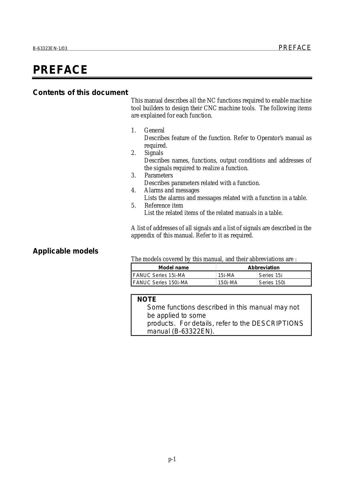
The models covered by this manual, and their abbreviations are :

Model name


Abbreviation

FANUC Series 15i-MA

15i-MA


Series 15i

FANUC Series 150i-MA

150i-MA


Series 150i

NOTE

Some functions described in this manual may not be applied to some

products. For details, refer to the DESCRIPTIONS manual (B-63322EN).

p-1

PREFACE

B-63323EN-1/03

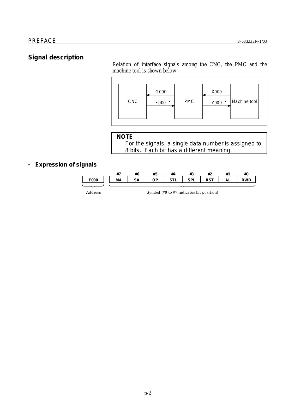
Signal description

- Expression of signals

F000

Relation of interface signals among the CNC, the PMC and the machine tool is shown below:


G000

-


X000

-


CNC

F000

-

PMC

Y000

-

Machine tool

NOTE

For the signals, a single data number is assigned to 8 bits. Each bit has a different meaning.

#7

#6

#5

#4

#3

#2

#1

#0

MA

SA

OP

STL

SPL

RST

AL

RWD


p-2

B-63323EN-1/03

PREFACE

Parameter description

Parameters are classified by data type as follows :

Data type

Valid data range

Remarks


Bit


Bit axis

0 or 1


Bit spindle


Integer

0 to ± 999999999

In some parameters, signs are


Integer axis


ignored.


Integer spindle


Real

Standard parameter


Real axis


See setting table.


Real spindle


NOTE

1For the bit type, bit axis type, and bit spindle type parameters, a single data number is assigned to 8 bits. Each bit has a different meaning.

2The axis type allows data to be set separately for each control axis.

3The spindle type allows data to be set separately for each spindle.

4The valid data range for each data type indicates a general range. The range varies according to the parameters. For the valid data range of a specific parameter, see the explanation of the parameter.

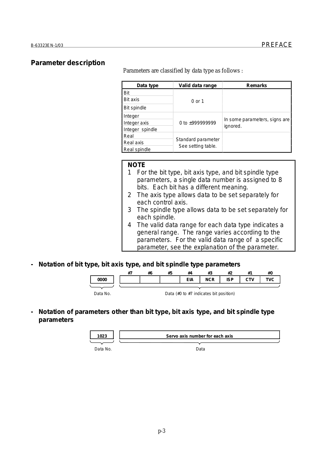
-Notation of bit type, bit axis type, and bit spindle type parameters

#7

#6

#5

#4

#3

#2

#1

#0

0000


EIA

NCR

ISP

CTV

TVC

Data No.


Data (#0 to #7 indicates bit position)


-Notation of parameters other than bit type, bit axis type, and bit spindle type parameters

1023

Servo axis number for each axis

Data No.

Data

p-3

fanuc 150i Connection Manual

PREFACE

B-63323EN-1/03

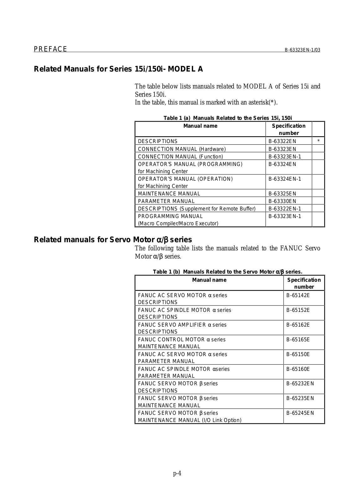
Related Manuals for Series 15i/150i- MODEL A

The table below lists manuals related to MODEL A of Series 15i and

Series 150i.

In the table, this manual is marked with an asterisk(*).

Table 1 (a) Manuals Related to the Series 15i, 150i

Manual name

Specification


number

DESCRIPTIONS

CONNECTION MANUAL (Hardware)

CONNECTION MANUAL (Function)

OPERATOR’S MANUAL (PROGRAMMING) for Machining Center

OPERATOR’S MANUAL (OPERATION) for Machining Center

MAINTENANCE MANUAL

PARAMETER MANUAL

DESCRIPTIONS (Supplement for Remote Buffer)

PROGRAMMING MANUAL

(Macro Compiler/Macro Executor)

B-63322EN * B-63323EN

B-63323EN-1

B-63324EN

B-63324EN-1

B-63325EN

B-63330EN

B-63322EN-1

B-63323EN-1

Related manuals for Servo Motor α /β series

The following table lists the manuals related to the FANUC Servo Motor α /β series.

Table 1 (b) Manuals Related to the Servo Motor α /β

Manual name

FANUC AC SERVO MOTOR α series

DESCRIPTIONS

FANUC AC SPINDLE MOTOR α series

DESCRIPTIONS

FANUC SERVO AMPLIFIER α series

DESCRIPTIONS

FANUC CONTROL MOTOR α series

MAINTENANCE MANUAL

FANUC AC SERVO MOTOR α series

PARAMETER MANUAL

FANUC AC SPINDLE MOTOR α series

PARAMETER MANUAL

FANUC SERVO MOTOR β series

DESCRIPTIONS

FANUC SERVO MOTOR β series

MAINTENANCE MANUAL

FANUC SERVO MOTOR β series

MAINTENANCE MANUAL (I/O Link Option)

series.

Specification

number

B-65142E

B-65152E

B-65162E

B-65165E

B-65150E

B-65160E

B-65232EN

B-65235EN

B-65245EN

p-4

B-63323EN-1/03

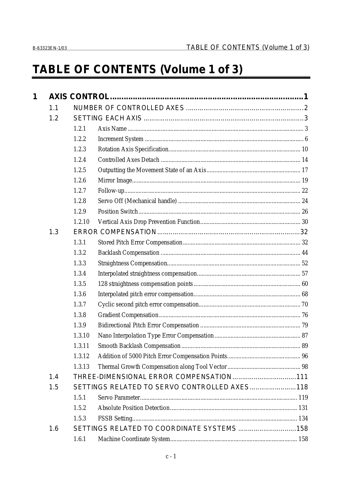
TABLE OF CONTENTS (Volume 1 of 3)

TABLE OF CONTENTS (Volume 1 of 3)

1 AXIS CONTROL.....................................................................................

1

1.1

NUMBER OF CONTROLLED AXES .............................................................

2

1.2

SETTING EACH AXIS ...................................................................................

3


1.2.1

Axis Name ...............................................................................................................

3


1.2.2

Increment System ....................................................................................................

6


1.2.3

Rotation Axis Specification...................................................................................

10


1.2.4

Controlled Axes Detach ........................................................................................

14


1.2.5

Outputting the Movement State of an Axis ...........................................................

17


1.2.6

Mirror Image..........................................................................................................

19


1.2.7

Follow-up...............................................................................................................

22


1.2.8

Servo Off (Mechanical handle) .............................................................................

24


1.2.9

Position Switch ......................................................................................................

26


1.2.10

Vertical Axis Drop Prevention Function...............................................................

30

1.3

ERROR COMPENSATION..........................................................................

32


1.3.1

Stored Pitch Error Compensation ..........................................................................

32


1.3.2

Backlash Compensation ........................................................................................

44


1.3.3

Straightness Compensation....................................................................................

52


1.3.4

Interpolated straightness compensation.................................................................

57


1.3.5

128 straightness compensation points ...................................................................

60


1.3.6

Interpolated pitch error compensation...................................................................

68


1.3.7

Cyclic second pitch error compensation................................................................

70


1.3.8

Gradient Compensation .........................................................................................

76


1.3.9

Bidirectional Pitch Error Compensation ...............................................................

79


1.3.10

Nano Interpolation Type Error Compensation ......................................................

87


1.3.11

Smooth Backlash Compensation ...........................................................................

89


1.3.12

Addition of 5000 Pitch Error Compensation Points..............................................

96


1.3.13

Thermal Growth Compensation along Tool Vector ..............................................

98

1.4

THREE-DIMENSIONAL ERROR COMPENSATION.................................

111

1.5

SETTINGS RELATED TO SERVO CONTROLLED AXES........................

118


1.5.1

Servo Parameter...................................................................................................

119


1.5.2

Absolute Position Detection ................................................................................

131


1.5.3

FSSB Setting........................................................................................................

134

1.6

SETTINGS RELATED TO COORDINATE SYSTEMS ..............................

158


1.6.1

Machine Coordinate System................................................................................

158

c - 1

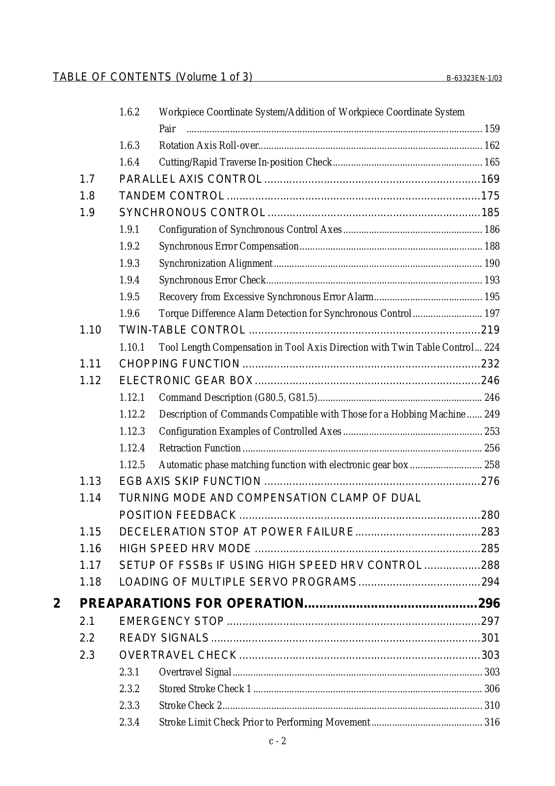
TABLE OF CONTENTS (Volume 1 of 3)

B-63323EN-1/03

1.6.2Workpiece Coordinate System/Addition of Workpiece Coordinate System


Pair ...................................................................................................................

159


1.6.3

Rotation Axis Roll-over.......................................................................................

162


1.6.4

Cutting/Rapid Traverse In-position Check..........................................................

165

1.7

PARALLEL AXIS CONTROL .....................................................................

169

1.8

TANDEM CONTROL .................................................................................

175

1.9

SYNCHRONOUS CONTROL ....................................................................

185


1.9.1

Configuration of Synchronous Control Axes ......................................................

186


1.9.2

Synchronous Error Compensation.......................................................................

188


1.9.3

Synchronization Alignment .................................................................................

190


1.9.4

Synchronous Error Check....................................................................................

193


1.9.5

Recovery from Excessive Synchronous Error Alarm..........................................

195


1.9.6

Torque Difference Alarm Detection for Synchronous Control...........................

197

1.10

TWIN-TABLE CONTROL ..........................................................................

219


1.10.1

Tool Length Compensation in Tool Axis Direction with Twin Table Control...

224

1.11

CHOPPING FUNCTION ............................................................................

232

1.12

ELECTRONIC GEAR BOX ........................................................................

246


1.12.1

Command Description (G80.5, G81.5)................................................................

246


1.12.2

Description of Commands Compatible with Those for a Hobbing Machine ......

249


1.12.3

Configuration Examples of Controlled Axes ......................................................

253


1.12.4

Retraction Function .............................................................................................

256


1.12.5

Automatic phase matching function with electronic gear box ............................

258

1.13 EGB AXIS SKIP FUNCTION .....................................................................

276

1.14TURNING MODE AND COMPENSATION CLAMP OF DUAL


POSITION FEEDBACK .............................................................................

280

1.15

DECELERATION STOP AT POWER FAILURE........................................

283

1.16

HIGH SPEED HRV MODE ........................................................................

285

1.17

SETUP OF FSSBs IF USING HIGH SPEED HRV CONTROL ..................

288

1.18

LOADING OF MULTIPLE SERVO PROGRAMS.......................................

294

2 PREAPARATIONS FOR OPERATION...............................................

296

2.1

EMERGENCY STOP .................................................................................

297

2.2

READY SIGNALS ......................................................................................

301

2.3

OVERTRAVEL CHECK .............................................................................

303


2.3.1

Overtravel Signal .................................................................................................

303


2.3.2 Stored Stroke Check 1 .........................................................................................

306


2.3.3

Stroke Check 2.....................................................................................................

310


2.3.4 Stroke Limit Check Prior to Performing Movement ...........................................

316


c - 2


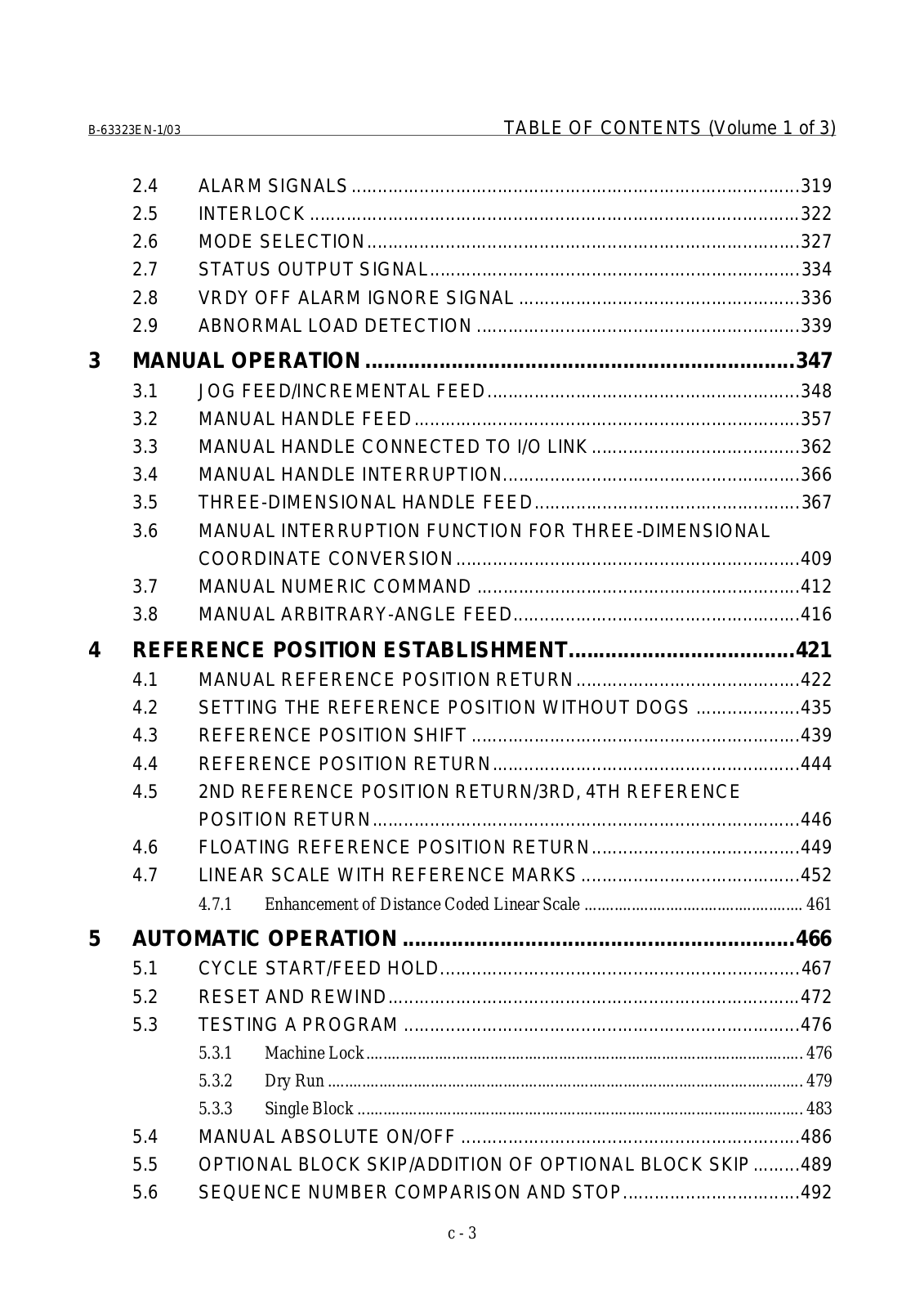
B-63323EN-1/03

TABLE OF CONTENTS (Volume 1 of 3)

2.4

ALARM SIGNALS ......................................................................................

319

2.5

INTERLOCK ..............................................................................................

322

2.6

MODE SELECTION...................................................................................

327

2.7

STATUS OUTPUT SIGNAL.......................................................................

334

2.8

VRDY OFF ALARM IGNORE SIGNAL ......................................................

336

2.9

ABNORMAL LOAD DETECTION ..............................................................

339

3 MANUAL OPERATION ......................................................................

347

3.1

JOG FEED/INCREMENTAL FEED............................................................

348

3.2

MANUAL HANDLE FEED..........................................................................

357

3.3

MANUAL HANDLE CONNECTED TO I/O LINK ........................................

362

3.4

MANUAL HANDLE INTERRUPTION.........................................................

366

3.5

THREE-DIMENSIONAL HANDLE FEED...................................................

367

3.6MANUAL INTERRUPTION FUNCTION FOR THREE-DIMENSIONAL


COORDINATE CONVERSION..................................................................

409

3.7

MANUAL NUMERIC COMMAND ..............................................................

412

3.8

MANUAL ARBITRARY-ANGLE FEED.......................................................

416

4 REFERENCE POSITION ESTABLISHMENT.....................................

421

4.1

MANUAL REFERENCE POSITION RETURN...........................................

422

4.2

SETTING THE REFERENCE POSITION WITHOUT DOGS ....................

435

4.3

REFERENCE POSITION SHIFT ...............................................................

439

4.4

REFERENCE POSITION RETURN...........................................................

444

4.52ND REFERENCE POSITION RETURN/3RD, 4TH REFERENCE


POSITION RETURN..................................................................................

446

4.6

FLOATING REFERENCE POSITION RETURN........................................

449

4.7

LINEAR SCALE WITH REFERENCE MARKS ..........................................

452


4.7.1 Enhancement of Distance Coded Linear Scale ...................................................

461

5 AUTOMATIC OPERATION ................................................................

466

5.1

CYCLE START/FEED HOLD.....................................................................

467

5.2

RESET AND REWIND...............................................................................

472

5.3

TESTING A PROGRAM ............................................................................

476


5.3.1

Machine Lock ......................................................................................................

476


5.3.2

Dry Run ...............................................................................................................

479


5.3.3

Single Block ........................................................................................................

483

5.4

MANUAL ABSOLUTE ON/OFF .................................................................

486

5.5

OPTIONAL BLOCK SKIP/ADDITION OF OPTIONAL BLOCK SKIP.........

489

5.6

SEQUENCE NUMBER COMPARISON AND STOP..................................

492

c - 3

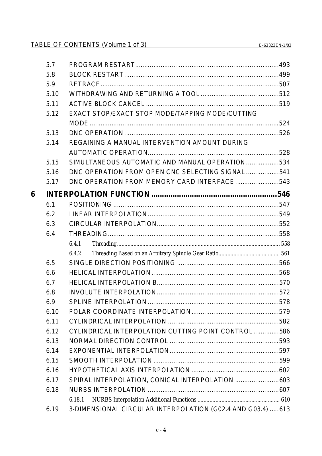
TABLE OF CONTENTS (Volume 1 of 3)

B-63323EN-1/03

5.7

PROGRAM RESTART...............................................................................

493

5.8

BLOCK RESTART .....................................................................................

499

5.9

RETRACE..................................................................................................

507

5.10

WITHDRAWING AND RETURNING A TOOL ...........................................

512

5.11

ACTIVE BLOCK CANCEL .........................................................................

519

5.12EXACT STOP/EXACT STOP MODE/TAPPING MODE/CUTTING

MODE ........................................................................................................

524

5.13 DNC OPERATION .....................................................................................

526

5.14REGAINING A MANUAL INTERVENTION AMOUNT DURING


AUTOMATIC OPERATION........................................................................

528

5.15

SIMULTANEOUS AUTOMATIC AND MANUAL OPERATION..................

534

5.16

DNC OPERATION FROM OPEN CNC SELECTING SIGNAL ..................

541

5.17

DNC OPERATION FROM MEMORY CARD INTERFACE ........................

543

6 INTERPOLATION FUNCTION ...........................................................

546

6.1

POSITIONING ...........................................................................................

547

6.2

LINEAR INTERPOLATION ........................................................................

549

6.3

CIRCULAR INTERPOLATION...................................................................

552

6.4

THREADING..............................................................................................

558


6.4.1 Threading.............................................................................................................

558


6.4.2 Threading Based on an Arbitrary Spindle Gear Ratio.........................................

561

6.5

SINGLE DIRECTION POSITIONING ........................................................

566

6.6

HELICAL INTERPOLATION ......................................................................

568

6.7

HELICAL INTERPOLATION B...................................................................

570

6.8

INVOLUTE INTERPOLATION ...................................................................

572

6.9

SPLINE INTERPOLATION ........................................................................

578

6.10

POLAR COORDINATE INTERPOLATION................................................

579

6.11

CYLINDRICAL INTERPOLATION .............................................................

582

6.12

CYLINDRICAL INTERPOLATION CUTTING POINT CONTROL ..............

586

6.13

NORMAL DIRECTION CONTROL ............................................................

593

6.14

EXPONENTIAL INTERPOLATION............................................................

597

6.15

SMOOTH INTERPOLATION .....................................................................

599

6.16

HYPOTHETICAL AXIS INTERPOLATION ................................................

602

6.17

SPIRAL INTERPOLATION, CONICAL INTERPOLATION ........................

603

6.18

NURBS INTERPOLATION ........................................................................

607


6.18.1 NURBS Interpolation Additional Functions .......................................................

610

6.19

3-DIMENSIONAL CIRCULAR INTERPOLATION (G02.4 AND G03.4) .....

613

c - 4

B-63323EN-1/03

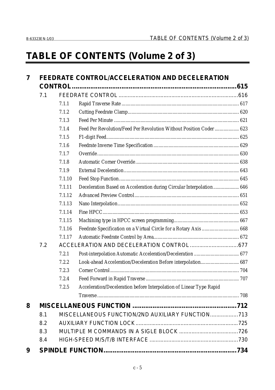
TABLE OF CONTENTS (Volume 2 of 3)

TABLE OF CONTENTS (Volume 2 of 3)

7 FEEDRATE CONTROL/ACCELERATION AND DECELERATION


CONTROL

..........................................................................................

615

7.1

FEEDRATE CONTROL .............................................................................

616


7.1.1

Rapid Traverse Rate ............................................................................................

617


7.1.2 .......................................................................................

Cutting Feedrate Clamp

620


7.1.3 ..................................................................................................

Feed Per Minute

621


7.1.4 ...................

Feed Per Revolution/Feed Per Revolution Without Position Coder

623


7.1.5 ........................................................................................................

F1 - digit Feed

625


7.1.6 ...................................................................

Feedrate Inverse Time Specification

629


7.1.7 ...............................................................................................................

Override

630


7.1.8 .................................................................................

Automatic Corner Override

638


7.1.9 ..........................................................................................

External Deceleration

643


7.1.10 ..............................................................................................

Feed Stop Function

645


7.1.11 ....................

Deceleration Based on Acceleration during Circular Interpolation

646


7.1.12 ..................................................................................

Advanced Preview Control

651


7.1.13 ...............................................................................................

Nano Interpolation

652


7.1.14 ...........................................................................................................

Fine HPCC

653


7.1.15 ...................................................

Machining type in HPCC screen programming

667


7.1.16 .............................

Feedrate Specification on a Virtual Circle for a Rotary Axis

668


7.1.17 ...................................................................

Automatic Feedrate Control by Area

672

7.2

ACCELERATION ...............................AND DECELERATION CONTROL

677


7.2.1 ...................................

Post - interpolation Automatic Acceleration/Deceleration

677


7.2.2 ..............................

Look - ahead Acceleration/Deceleration Before interpolation

687


7.2.3 .....................................................................................................

Corner Control

704


7.2.4 .........................................................................

Feed Forward in Rapid Traverse

707


7.2.5

Acceleration/Deceleration before Interpolation of Linear Type Rapid


...............................................................................................................

Traverse

708

8

MISCELLANEOUS FUNCTION .........................................................

712


8.1

MISCELLANEOUS FUNCTION/2ND AUXILIARY FUNCTION..................

713


8.2

AUXILIARY FUNCTION LOCK ..................................................................

725


8.3

MULTIPLE M COMMANDS IN A SIGLE BLOCK ......................................

726


8.4

HIGH-SPEED M/S/T/B INTERFACE .........................................................

730

9

SPINDLE FUNCTION.........................................................................

734

c - 5

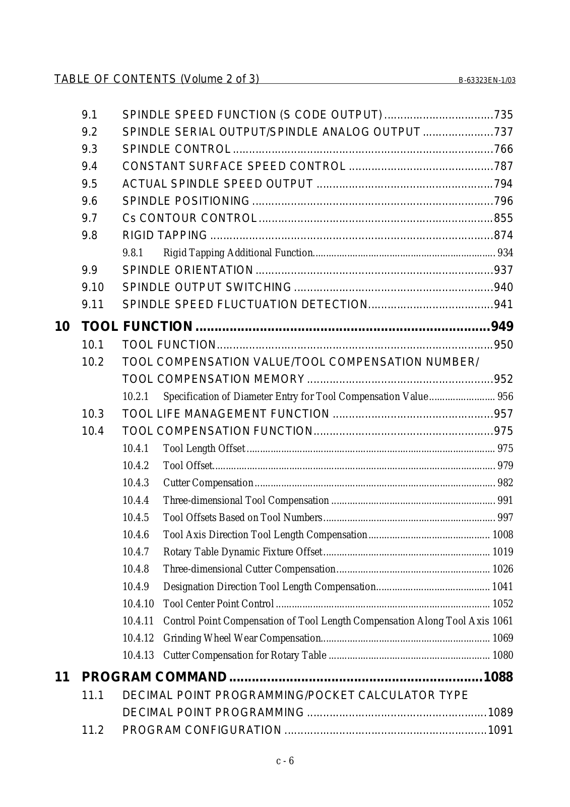
TABLE OF CONTENTS (Volume 2 of 3)

B-63323EN-1/03

9.1

SPINDLE SPEED FUNCTION (S CODE OUTPUT) ..................................

735

9.2

SPINDLE SERIAL OUTPUT/SPINDLE ANALOG OUTPUT ......................

737

9.3

SPINDLE CONTROL .................................................................................

766

9.4

CONSTANT SURFACE SPEED CONTROL .............................................

787

9.5

ACTUAL SPINDLE SPEED OUTPUT .......................................................

794

9.6

SPINDLE POSITIONING ...........................................................................

796

9.7

Cs CONTOUR CONTROL.........................................................................

855

9.8

RIGID TAPPING ........................................................................................

874


9.8.1 Rigid Tapping Additional Function.....................................................................

934

9.9

SPINDLE ORIENTATION ..........................................................................

937

9.10

SPINDLE OUTPUT SWITCHING ..............................................................

940

9.11

SPINDLE SPEED FLUCTUATION DETECTION.......................................

941

10 TOOL FUNCTION ..............................................................................

949

10.1

TOOL FUNCTION......................................................................................

950

10.2TOOL COMPENSATION VALUE/TOOL COMPENSATION NUMBER/

TOOL COMPENSATION MEMORY ..........................................................

952

10.2.1

Specification of Diameter Entry for Tool Compensation Value .........................

956

10.3 TOOL LIFE MANAGEMENT FUNCTION ..................................................

957

10.4 TOOL COMPENSATION FUNCTION........................................................

975

10.4.1

Tool Length Offset ..............................................................................................

975

10.4.2

Tool Offset...........................................................................................................

979

10.4.3

Cutter Compensation ...........................................................................................

982

10.4.4

Three-dimensional Tool Compensation ..............................................................

991

10.4.5

Tool Offsets Based on Tool Numbers .................................................................

997

10.4.6

Tool Axis Direction Tool Length Compensation..............................................

1008

10.4.7

Rotary Table Dynamic Fixture Offset ...............................................................

1019

10.4.8

Three-dimensional Cutter Compensation..........................................................

1026

10.4.9

Designation Direction Tool Length Compensation...........................................

1041

10.4.10

Tool Center Point Control .................................................................................

1052

10.4.11

Control Point Compensation of Tool Length Compensation Along Tool Axis 1061

10.4.12

Grinding Wheel Wear Compensation................................................................

1069

10.4.13

Cutter Compensation for Rotary Table .............................................................

1080

11 PROGRAM COMMAND ...................................................................

1088

11.1DECIMAL POINT PROGRAMMING/POCKET CALCULATOR TYPE

DECIMAL POINT PROGRAMMING ........................................................

1089

11.2 PROGRAM CONFIGURATION ...............................................................

1091

c - 6

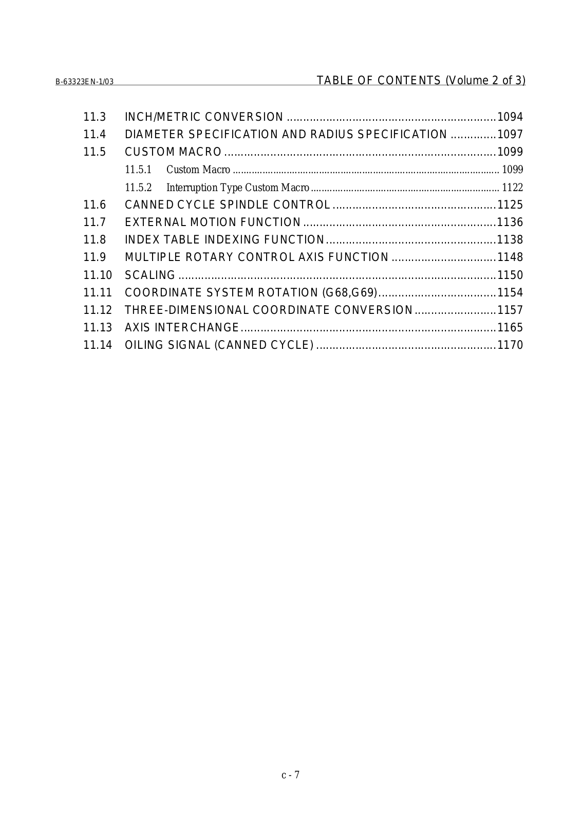
B-63323EN-1/03

TABLE OF CONTENTS (Volume 2 of 3)

11.3

INCH/METRIC CONVERSION ................................................................

1094

11.4

DIAMETER SPECIFICATION AND RADIUS SPECIFICATION ..............

1097

11.5

CUSTOM MACRO ...................................................................................

1099


11.5.1 Custom Macro ...................................................................................................

1099


11.5.2 Interruption Type Custom Macro ......................................................................

1122

11.6

CANNED CYCLE SPINDLE CONTROL ..................................................

1125

11.7

EXTERNAL MOTION FUNCTION ...........................................................

1136

11.8

INDEX TABLE INDEXING FUNCTION....................................................

1138

11.9

MULTIPLE ROTARY CONTROL AXIS FUNCTION ................................

1148

11.10

SCALING .................................................................................................

1150

11.11

COORDINATE SYSTEM ROTATION (G68,G69)....................................

1154

11.12

THREE-DIMENSIONAL COORDINATE CONVERSION .........................

1157

11.13

AXIS INTERCHANGE..............................................................................

1165

11.14

OILING SIGNAL (CANNED CYCLE) .......................................................

1170

c - 7

TABLE OF CONTENTS (Volume 3 of 3)

B-63323EN-1/03

TABLE OF CONTENTS (Volume 1 of 3)

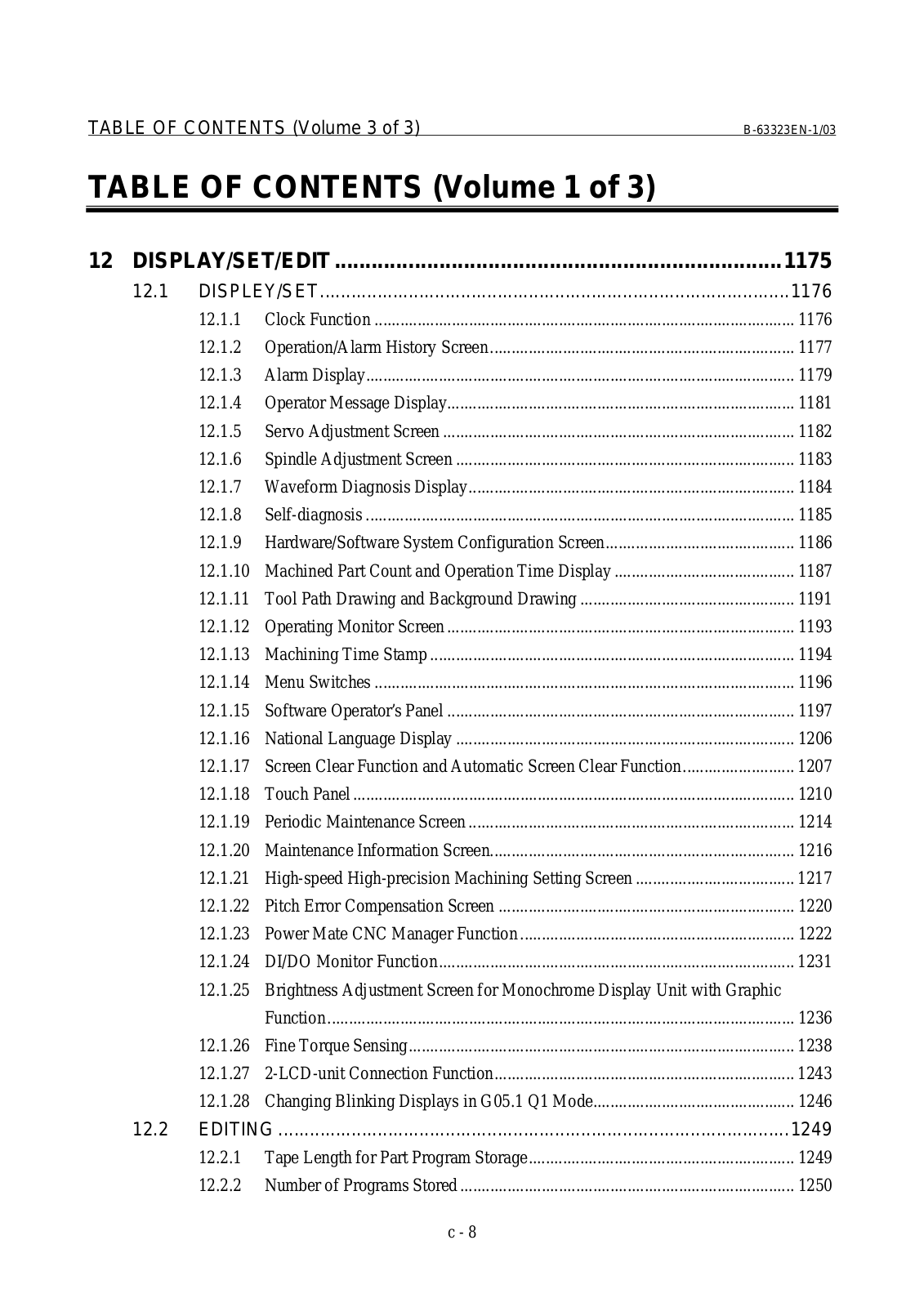
12 DISPLAY/SET/EDIT .........................................................................

1175

12.1

DISPLEY/SET..........................................................................................

1176


12.1.1

Clock Function ..................................................................................................

1176


12.1.2

Operation/Alarm History Screen .......................................................................

1177


12.1.3

Alarm Display....................................................................................................

1179


12.1.4

Operator Message Display.................................................................................

1181


12.1.5

Servo Adjustment Screen ..................................................................................

1182


12.1.6

Spindle Adjustment Screen ...............................................................................

1183


12.1.7

Waveform Diagnosis Display............................................................................

1184


12.1.8

Self-diagnosis ....................................................................................................

1185


12.1.9

Hardware/Software System Configuration Screen............................................

1186


12.1.10

Machined Part Count and Operation Time Display ..........................................

1187


12.1.11

Tool Path Drawing and Background Drawing ..................................................

1191


12.1.12

Operating Monitor Screen .................................................................................

1193


12.1.13

Machining Time Stamp .....................................................................................

1194


12.1.14

Menu Switches ..................................................................................................

1196


12.1.15

Software Operator’s Panel .................................................................................

1197


12.1.16

National Language Display ...............................................................................

1206


12.1.17

Screen Clear Function and Automatic Screen Clear Function..........................

1207


12.1.18

Touch Panel .......................................................................................................

1210


12.1.19

Periodic Maintenance Screen ............................................................................

1214


12.1.20

Maintenance Information Screen.......................................................................

1216


12.1.21

High-speed High-precision Machining Setting Screen .....................................

1217


12.1.22

Pitch Error Compensation Screen .....................................................................

1220


12.1.23

Power Mate CNC Manager Function ................................................................

1222


12.1.24

DI/DO Monitor Function...................................................................................

1231


12.1.25 Brightness Adjustment Screen for Monochrome Display Unit with Graphic


Function .............................................................................................................

1236


12.1.26

Fine Torque Sensing..........................................................................................

1238


12.1.27

2-LCD-unit Connection Function......................................................................

1243


12.1.28

Changing Blinking Displays in G05.1 Q1 Mode...............................................

1246

12.2

EDITING ..................................................................................................

1249


12.2.1

Tape Length for Part Program Storage..............................................................

1249


12.2.2

Number of Programs Stored ..............................................................................

1250

c - 8

B-63323EN-1/03


TABLE OF CONTENTS (Volume 3 of 3)


12.2.3

Memory Protection Keys...................................................................................

1251


12.2.4

Program Encryption...........................................................................................

1252


12.2.5

Background Editing ...........................................................................................

1256


12.2.6

Playback.............................................................................................................

1257


12.2.7

Automatic Sequence Number Insertion.............................................................

1259


12.2.8

Editing a Running Program ...............................................................................

1260


12.2.9

DO Signal Output by Soft Key..........................................................................

1261


12.3

READER/PUNCHER INTERFACE ..........................................................

1269

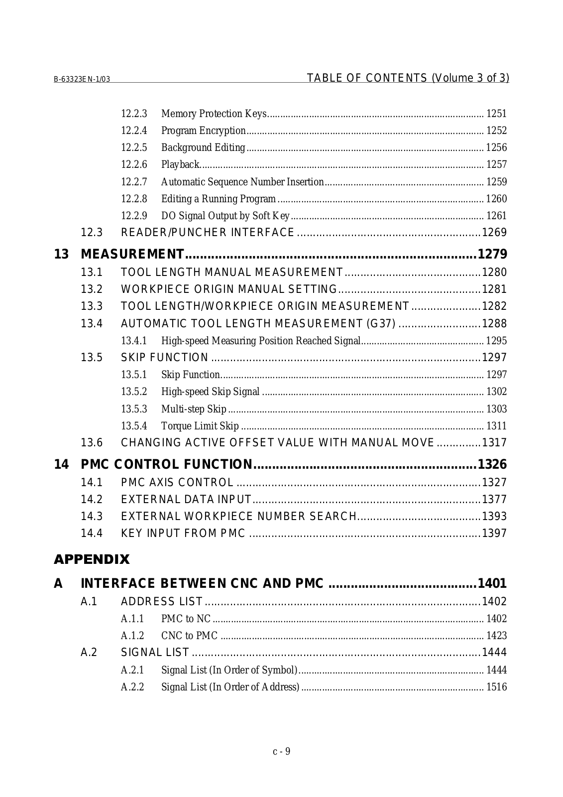
13

MEASUREMENT..............................................................................

1279


13.1

TOOL LENGTH MANUAL MEASUREMENT...........................................

1280


13.2

WORKPIECE ORIGIN MANUAL SETTING.............................................

1281


13.3

TOOL LENGTH/WORKPIECE ORIGIN MEASUREMENT ......................

1282


13.4

AUTOMATIC TOOL LENGTH MEASUREMENT (G37) ..........................

1288


13.4.1

High-speed Measuring Position Reached Signal...............................................

1295


13.5

SKIP FUNCTION .....................................................................................

1297


13.5.1

Skip Function.....................................................................................................

1297


13.5.2

High-speed Skip Signal .....................................................................................

1302


13.5.3

Multi-step Skip ..................................................................................................

1303


13.5.4

Torque Limit Skip .............................................................................................

1311


13.6

CHANGING ACTIVE OFFSET VALUE WITH MANUAL MOVE ..............

1317

14

PMC CONTROL FUNCTION............................................................

1326


14.1

PMC AXIS CONTROL .............................................................................

1327


14.2

EXTERNAL DATA INPUT........................................................................

1377


14.3

EXTERNAL WORKPIECE NUMBER SEARCH.......................................

1393


14.4

KEY INPUT FROM PMC .........................................................................

1397


A

INTERFACE BETWEEN CNC AND PMC ........................................

1401


A.1

ADDRESS LIST .......................................................................................

1402


A.1.1

PMC to NC ........................................................................................................

1402


A.1.2

CNC to PMC .....................................................................................................

1423


A.2

SIGNAL LIST ...........................................................................................

1444


A.2.1

Signal List (In Order of Symbol).......................................................................

1444


A.2.2

Signal List (In Order of Address) ......................................................................

1516

c - 9

B-63323EN-1/03

1.AXIS CONTROL

1 AXIS CONTROL

- 1 -

1.AXIS CONTROL B-63323EN-1/03

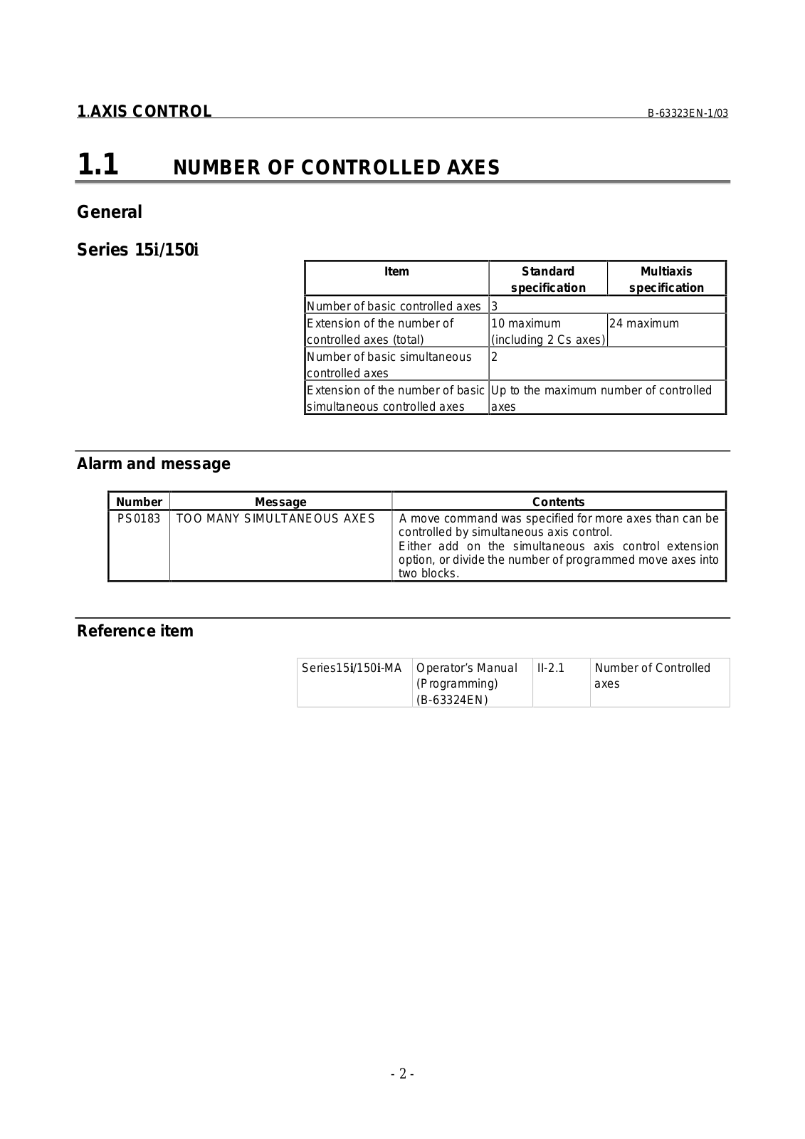
1.1

NUMBER OF CONTROLLED AXES


General


Series 15i/150i


Item


Standard

Multiaxis


specification

specification


Number of basic controlled axes


3


Extension of the number of


10 maximum

24 maximum


controlled axes (total)


(including 2 Cs axes)


Number of basic simultaneous


2


controlled axes


Extension of the number of basic

Up to the maximum number of controlled


simultaneous controlled axes


axes


Alarm and message


Number

Message


Contents


PS0183

TOO MANY SIMULTANEOUS AXES

A move command was specified for more axes than can be


controlled by simultaneous axis control.


Either add on the simultaneous axis control extension


option, or divide the number of programmed move axes into


two blocks.


Reference item

Series15i/150i-MA

Operator’s Manual

II-2.1

Number of Controlled


(Programming)


axes


(B-63324EN)


- 2 -

B-63323EN-1/03

1.AXIS CONTROL

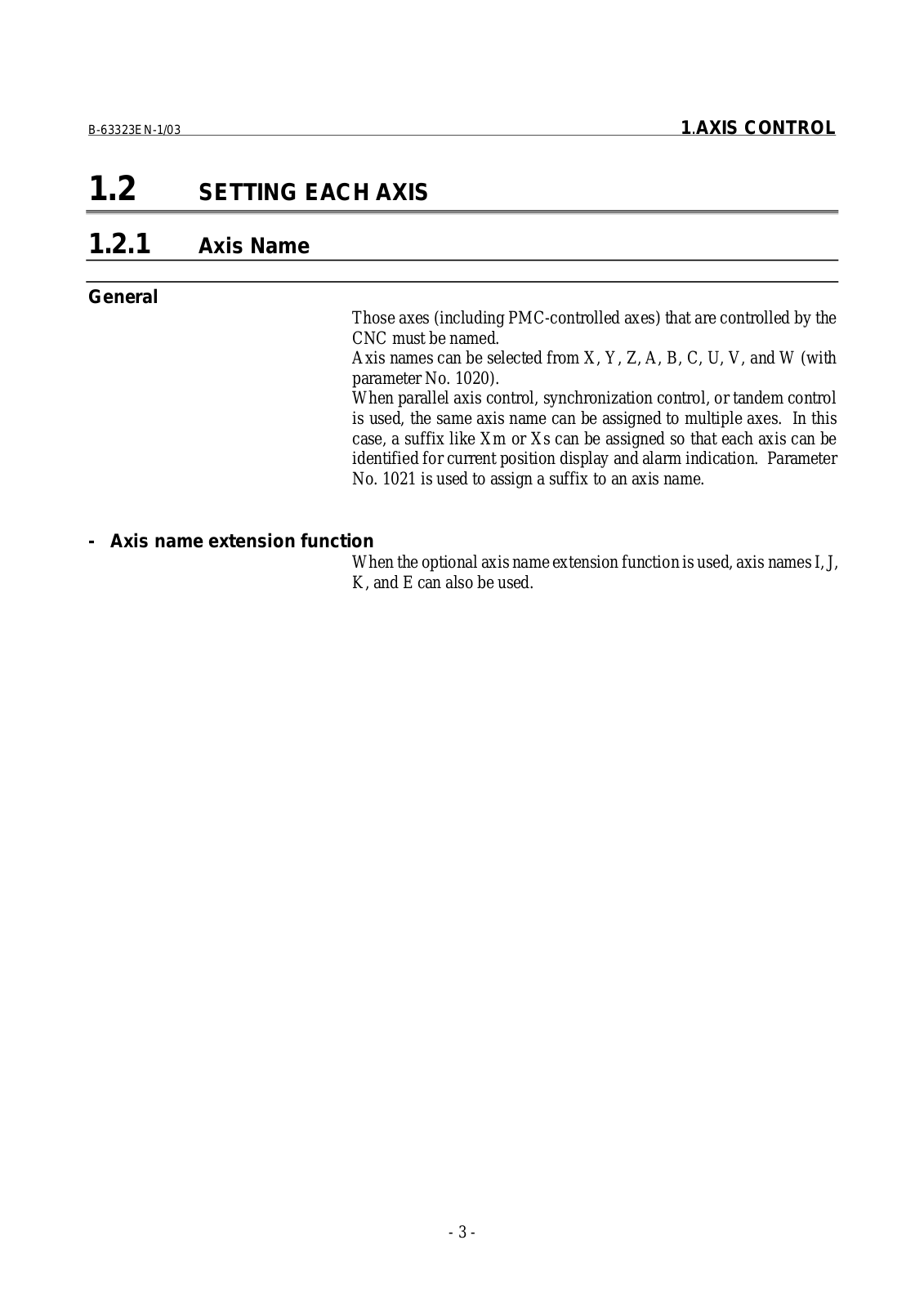
1.2 SETTING EACH AXIS

1.2.1 Axis Name

General

Those axes (including PMC-controlled axes) that are controlled by the CNC must be named.

Axis names can be selected from X, Y, Z, A, B, C, U, V, and W (with parameter No. 1020).

When parallel axis control, synchronization control, or tandem control is used, the same axis name can be assigned to multiple axes. In this case, a suffix like Xm or Xs can be assigned so that each axis can be identified for current position display and alarm indication. Parameter No. 1021 is used to assign a suffix to an axis name.

- Axis name extension function

When the optional axis name extension function is used, axis names I, J, K, and E can also be used.

- 3 -


1.AXIS CONTROL


B-63323EN-1/03


Parameter


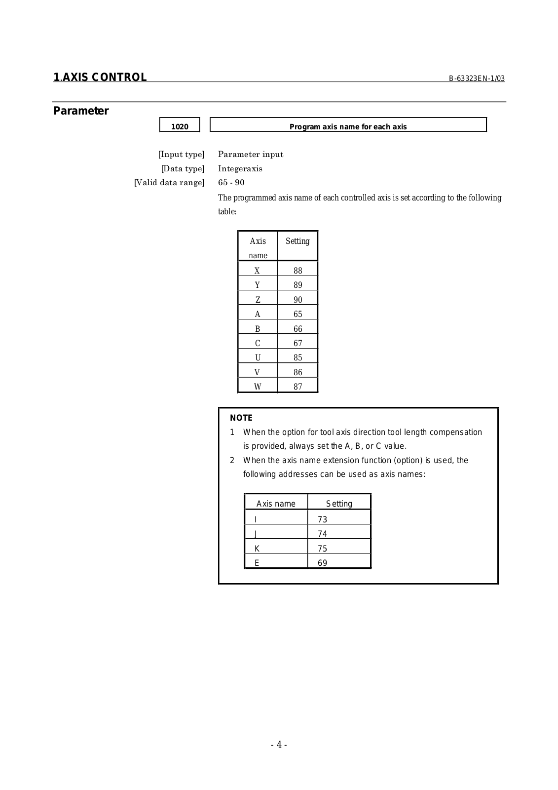
1020


Program axis name for each axis


The programmed axis name of each controlled axis is set according to the following table:

Axis

Setting

name


X

88

Y

89

Z

90

A

65

B

66

C

67

U

85

V

86

W

87

NOTE

1When the option for tool axis direction tool length compensation is provided, always set the A, B, or C value.

2When the axis name extension function (option) is used, the following addresses can be used as axis names:

Axis name

Setting

I

73

J

74

K

75

E

69

- 4 -

B-63323EN-1/03

1.AXIS CONTROL


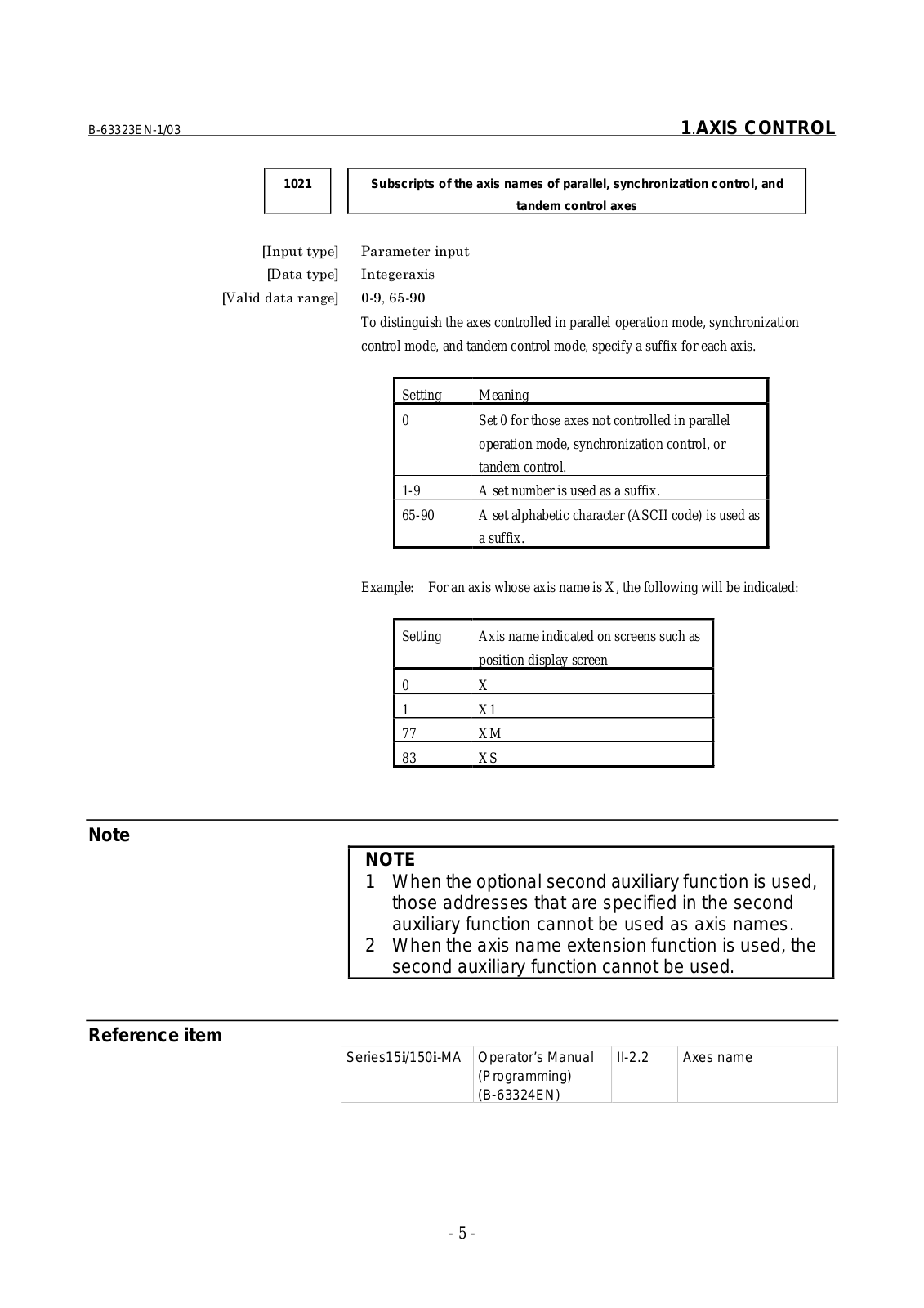
1021


Subscripts of the axis names of parallel, synchronization control, and


tandem control axes


To distinguish the axes controlled in parallel operation mode, synchronization


control mode, and tandem control mode, specify a suffix for each axis.

Setting Meaning

0Set 0 for those axes not controlled in parallel operation mode, synchronization control, or tandem control.

1-9

A set number is used as a suffix.

65-90

A set alphabetic character (ASCII code) is used as


a suffix.

Example: For an axis whose axis name is X, the following will be indicated:

Setting

Axis name indicated on screens such as


position display screen

0

X

1

X1

77

XM

83

XS

Note

NOTE

1When the optional second auxiliary function is used, those addresses that are specified in the second auxiliary function cannot be used as axis names.

2When the axis name extension function is used, the second auxiliary function cannot be used.

Reference item

Series15i/150i-MA

Operator’s Manual

II-2.2

Axes name


(Programming)


(B-63324EN)


- 5 -

1.AXIS CONTROL

B-63323EN-1/03

1.2.2 Increment System

General

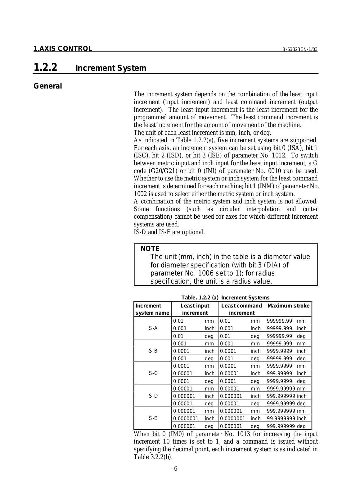
The increment system depends on the combination of the least input increment (input increment) and least command increment (output increment). The least input increment is the least increment for the programmed amount of movement. The least command increment is the least increment for the amount of movement of the machine.

The unit of each least increment is mm, inch, or deg.

As indicated in Table 1.2.2(a), five increment systems are supported. For each axis, an increment system can be set using bit 0 (ISA), bit 1 (ISC), bit 2 (ISD), or bit 3 (ISE) of parameter No. 1012. To switch between metric input and inch input for the least input increment, a G code (G20/G21) or bit 0 (INI) of parameter No. 0010 can be used. Whether to use the metric system or inch system for the least command increment is determined for each machine; bit 1 (INM) of parameter No. 1002 is used to select either the metric system or inch system.

A combination of the metric system and inch system is not allowed. Some functions (such as circular interpolation and cutter compensation) cannot be used for axes for which different increment systems are used.

IS-D and IS-E are optional.

NOTE

The unit (mm, inch) in the table is a diameter value for diameter specification (with bit 3 (DIA) of parameter No. 1006 set to 1); for radius specification, the unit is a radius value.


Table. 1.2.2 (a)

Increment Systems


Increment

Least input

Least command

Maximum stroke

system name

increment

increment


0.01

mm

0.01

mm

999999.99

mm

IS-A

0.001

inch

0.001

inch

99999.999

inch


0.01

deg

0.01

deg

999999.99

deg


0.001

mm

0.001

mm

99999.999

mm

IS-B

0.0001

inch

0.0001

inch

9999.9999

inch


0.001

deg

0.001

deg

99999.999

deg


0.0001

mm

0.0001

mm

9999.9999

mm

IS-C

0.00001

inch

0.00001

inch

999.99999

inch


0.0001

deg

0.0001

deg

9999.9999

deg


0.00001

mm

0.00001

mm

9999.99999 mm

IS-D

0.000001

inch

0.000001

inch

999.999999 inch


0.00001

deg

0.00001

deg

9999.99999 deg


0.000001

mm

0.000001

mm

999.999999 mm

IS-E

0.0000001

inch

0.0000001

inch

99.9999999 inch


0.000001

deg

0.000001

deg

999.999999 deg

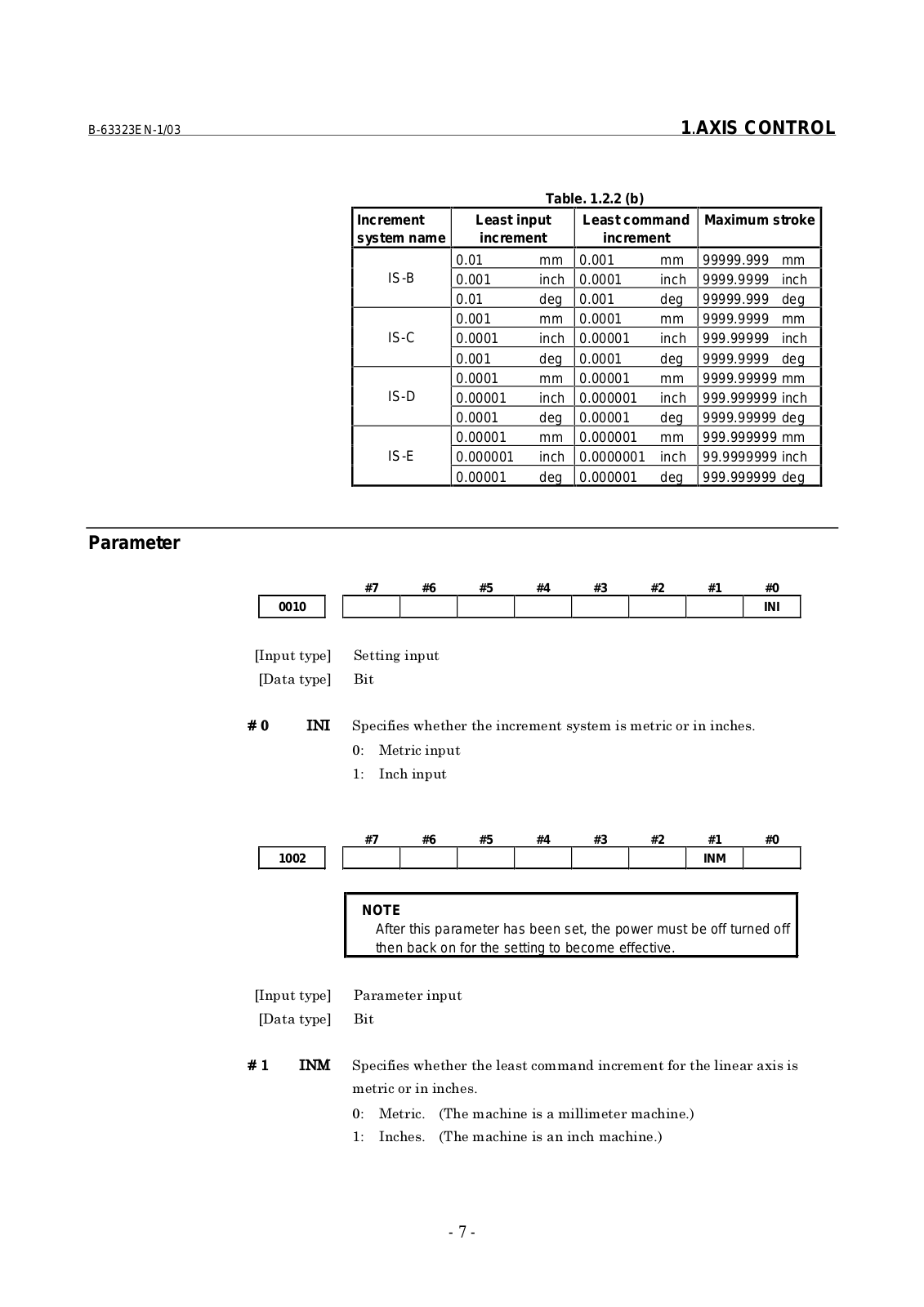
When bit 0 (IM0) of parameter No. 1013 for increasing the input increment 10 times is set to 1, and a command is issued without specifying the decimal point, each increment system is as indicated in Table 3.2.2(b).

- 6 -

B-63323EN-1/03


1.AXIS CONTROL


Table. 1.2.2 (b)


Increment

Least input

Least command

Maximum stroke


system name

increment

increment


0.01

mm

0.001

mm

99999.999

mm


IS-B

0.001

inch

0.0001

inch

9999.9999

inch


0.01

deg

0.001

deg

99999.999

deg


0.001

mm

0.0001

mm

9999.9999

mm


IS-C

0.0001

inch

0.00001

inch

999.99999

inch


0.001

deg

0.0001

deg

9999.9999

deg


0.0001

mm

0.00001

mm

9999.99999 mm


IS-D

0.00001

inch

0.000001

inch

999.999999 inch


0.0001

deg

0.00001

deg

9999.99999 deg


0.00001

mm

0.000001

mm

999.999999 mm


IS-E

0.000001

inch

0.0000001

inch

99.9999999 inch


0.00001

deg

0.000001

deg

999.999999 deg


Parameter

#7

#6

#5

#4

#3

#2

#1

#0

0010


INI


! " #$ $ $! ! % !$&

' ( !

)' !$

#7

#6

#5

#4

#3

#2

#1

#0

1002


INM


NOTE

After this parameter has been set, the power must be off turned off then back on for the setting to become effective.


)

(

! " #$ $ $!% ! "%$


! % !$&


'

( !& *+$!$!$&,


)'

!$& *+$!$!$!$&,

- 7 -

1.AXIS CONTROL


B-63323EN-1/03


#7

#6

#5

#4

#3

#2

#1

#0


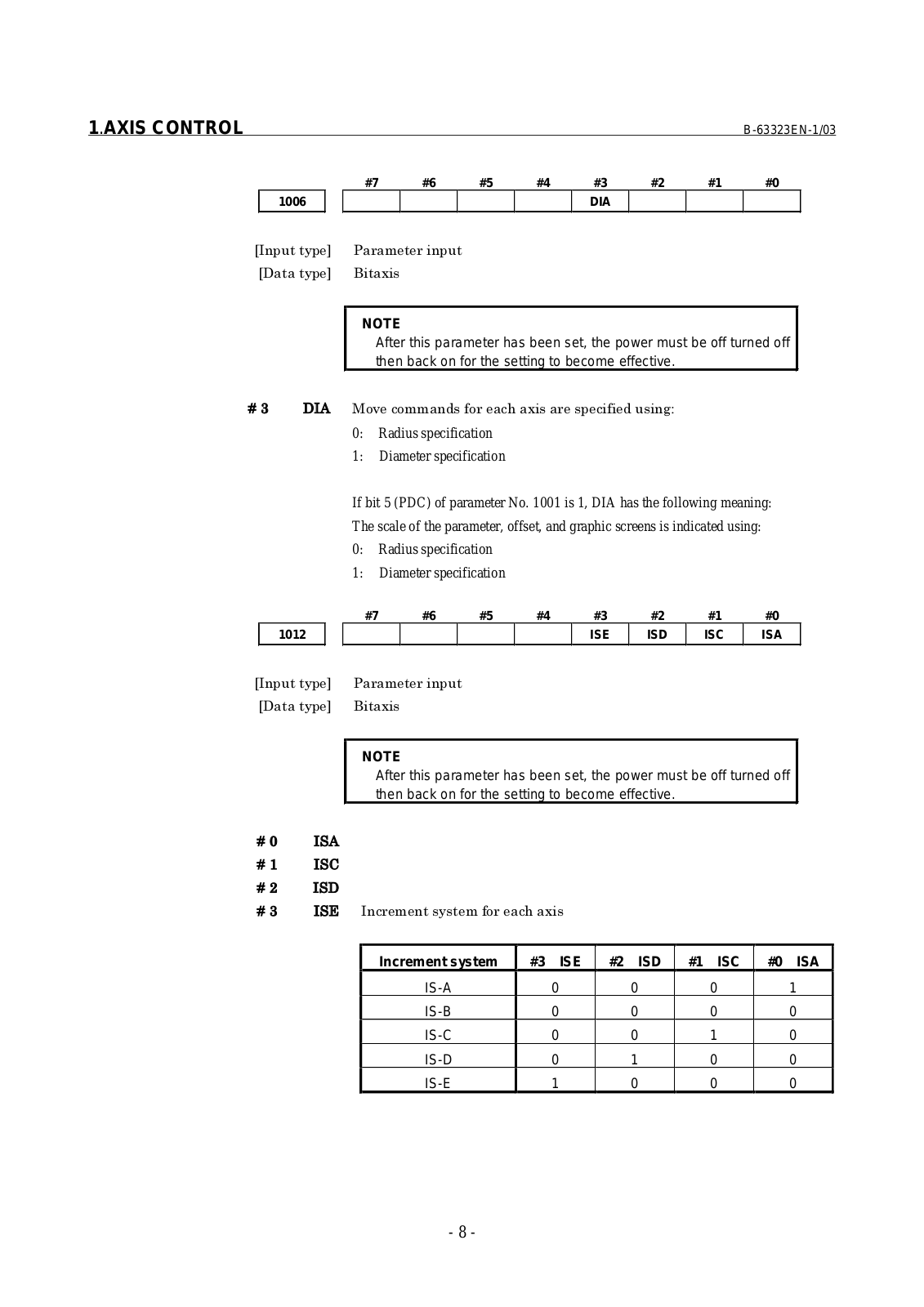
1006


DIA


NOTE

After this parameter has been set, the power must be off turned off then back on for the setting to become effective.

-

. (%/ !% "% !$! " '

0:Radius specification

1:Diameter specification

If bit 5 (PDC) of parameter No. 1001 is 1, DIA has the following meaning:

The scale of the parameter, offset, and graphic screens is indicated using:

0:Radius specification

1:Diameter specification

#7

#6

#5

#4

#3

#2

#1

#0

1012


ISE

ISD

ISC

ISA


NOTE

After this parameter has been set, the power must be off turned off then back on for the setting to become effective.


.


)

0


1


-

2 ! "% !$


Increment system

#3 ISE

#2 ISD

#1 ISC

#0 ISA


IS-A

0

0

0

1


IS-B

0

0

0

0


IS-C

0

0

1

0


IS-D

0

1

0

0


IS-E

1

0

0

0

- 8 -

B-63323EN-1/03


1.AXIS CONTROL


#7

#6


#5

#4

#3

#2

#1

#0


1013


IM0


(

! " #$ $%$! %" !$%


$!% ! #$!% #$%


$! % &


'

% % %$!% ! &


)'

%$!% ! &


3$.$!$!


! % 4 %$!% ! &


Reference item

Series15i/150i-MA

Operator’s Manual

II-2.3

Increment system


(Programming)


(B-63324EN)


- 9 -

1.AXIS CONTROL

B-63323EN-1/03

1.2.3 Rotation Axis Specification

General

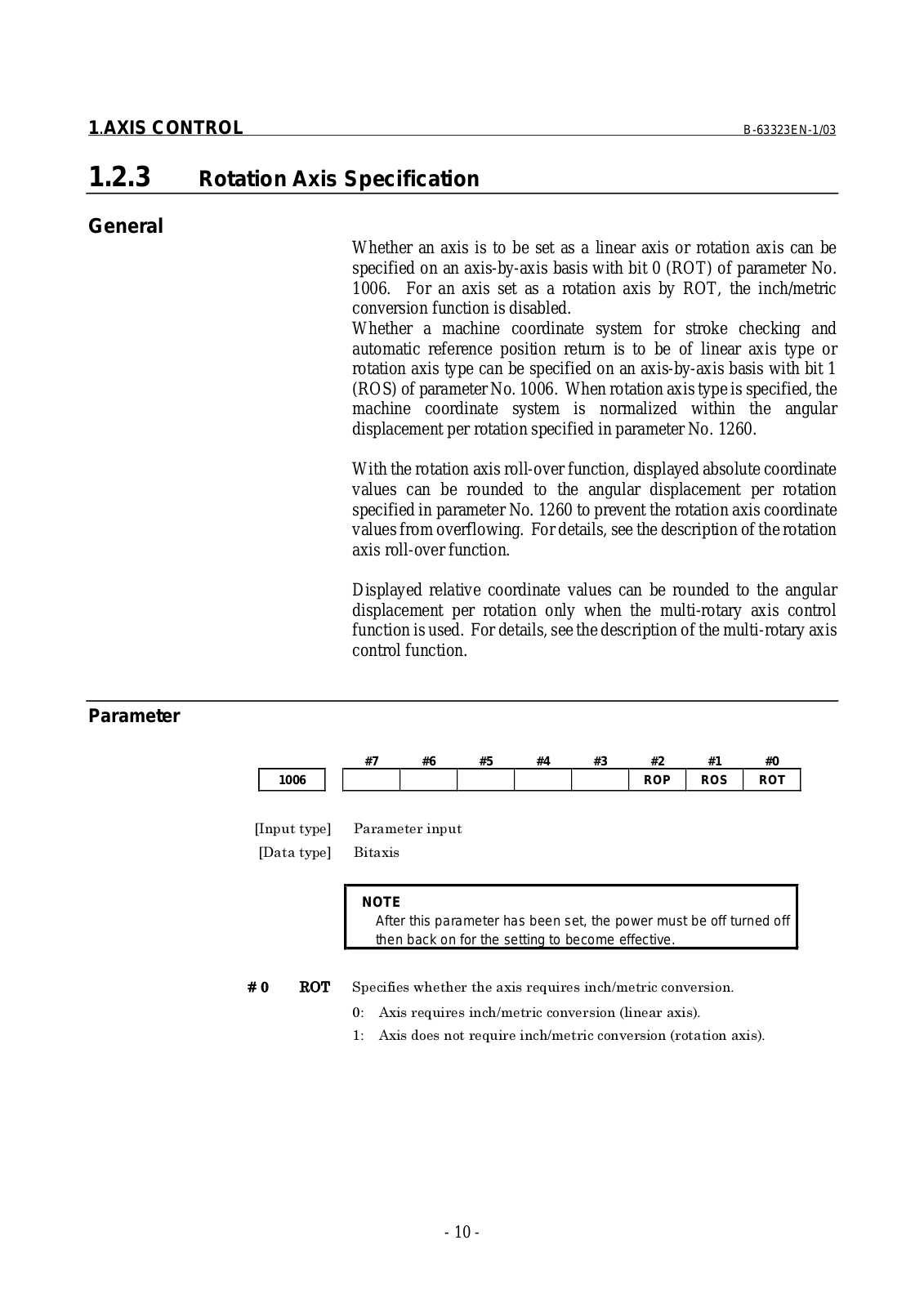
Whether an axis is to be set as a linear axis or rotation axis can be specified on an axis-by-axis basis with bit 0 (ROT) of parameter No. 1006. For an axis set as a rotation axis by ROT, the inch/metric conversion function is disabled.

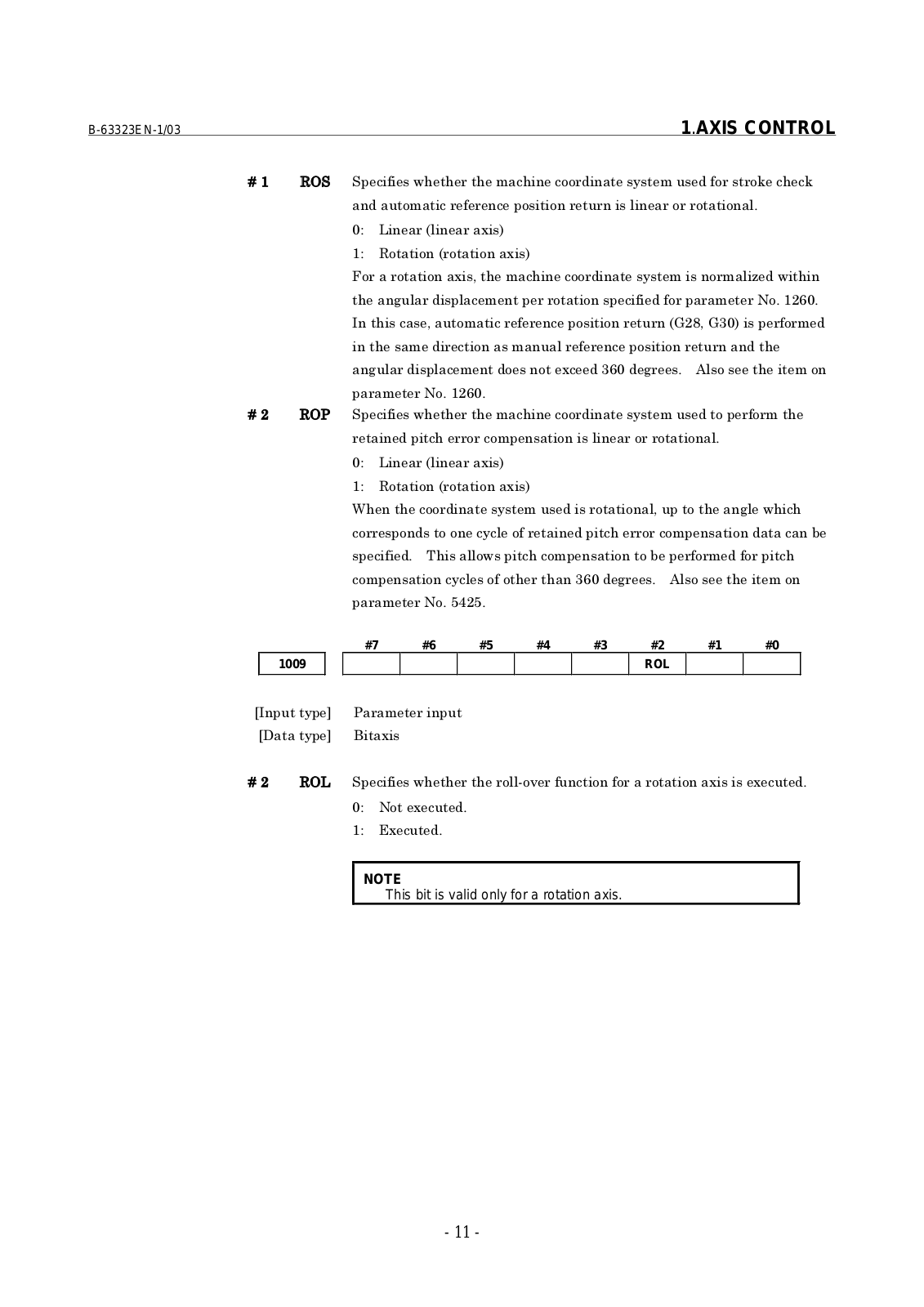
Whether a machine coordinate system for stroke checking and automatic reference position return is to be of linear axis type or rotation axis type can be specified on an axis-by-axis basis with bit 1 (ROS) of parameter No. 1006. When rotation axis type is specified, the machine coordinate system is normalized within the angular displacement per rotation specified in parameter No. 1260.

With the rotation axis roll-over function, displayed absolute coordinate values can be rounded to the angular displacement per rotation specified in parameter No. 1260 to prevent the rotation axis coordinate values from overflowing. For details, see the description of the rotation axis roll-over function.

Displayed relative coordinate values can be rounded to the angular displacement per rotation only when the multi-rotary axis control function is used. For details, see the description of the multi-rotary axis control function.

Parameter

#7

#6

#5

#4

#3

#2

#1

#0

1006


ROP

ROS

ROT


NOTE

After this parameter has been set, the power must be off turned off then back on for the setting to become effective.


56+ ! " #$ $ $7 !$8 ! !% / % &

' . 7 !$8 ! !% / % * ,&

)' . % % 7 !$8 ! !% / % * % % ,&

- 10 -

B-63323EN-1/03


1.AXIS CONTROL

)

56


! " #$ $ $!$!%% "% %9 !$!9


% ! " ! % % % % % &


'

: * ,


)'

5% % * % % ,


;% % %$!$!%% % < #$


$! % % ! " "%

%& )1 &


$! % ! " ! % % *=1> =-, "%


$! % " ! % %$


! % % !-& . %$%


%& )1 &


1

56


! " #$ $ $!$!%% % "%$


!$% !% % % % % &


'

: * ,


)'

5% % * % % ,


3$ $!%% % % %$#$!$


!% % % % ! ! %" !$% !% % ! 4


! " & +$%# !$!% % % 4 "% "% !$


!% % ! ! %" %$ $ -& . %$%


%& ?1 &


#7

#6

#5


#4

#3

#2

#1


#0


1009


ROL


1

56:


! " #$ $ $% %/ " ! % "% % % ! &


'

% ! &


)'

2 ! &


NOTE


This bit is valid only for a rotation axis.


- 11 -

1.AXIS CONTROL


B-63323EN-1/03


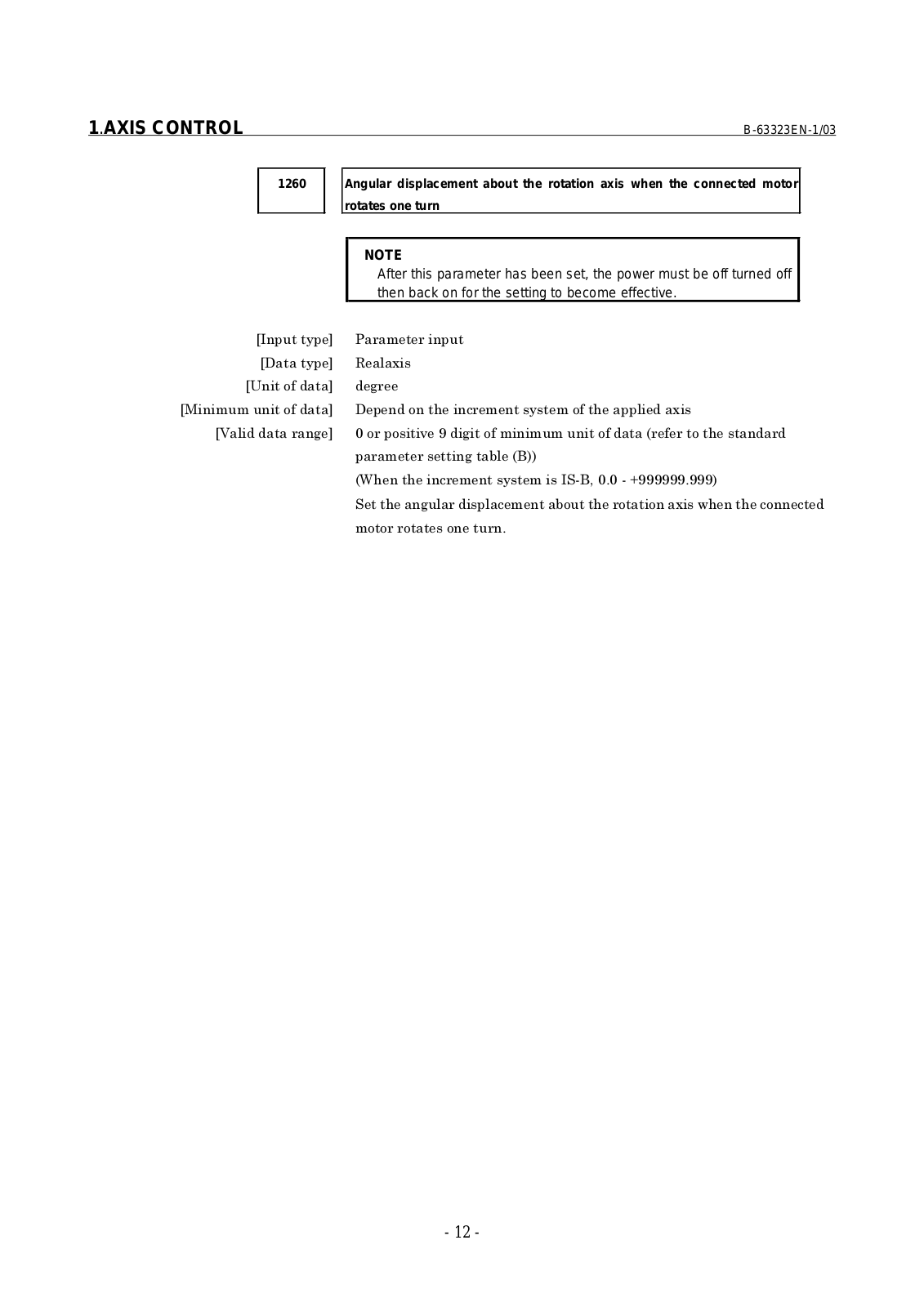
1260


Angular displacement about the rotation axis when the connected motor


rotates one turn


NOTE


After this parameter has been set, the power must be off turned off


then back on for the setting to become effective.


5

@ %"

( %" %$! %"$

% % / %" %" * " %$

4 * ,,

*3$ $! & A & ,

$! 4%$% % #$ $!% !

% % % % &

- 12 -

B-63323EN-1/03


1.AXIS CONTROL


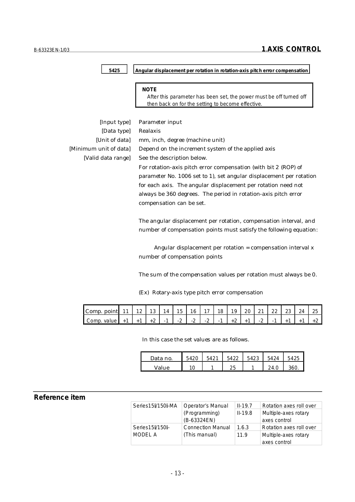
5425


Angular displacement per rotation in rotation-axis pitch error compensation


NOTE


After this parameter has been set, the power must be off turned off


then back on for the setting to become effective.


[Input type]


Parameter input


[Data type]


Realaxis


[Unit of data]


mm, inch, degree (machine unit)


[Minimum unit of data]


Depend on the increment system of the applied axis


[Valid data range]


See the description below.


For rotation-axis pitch error compensation (with bit 2 (ROP) of


parameter No. 1006 set to 1), set angular displacement per rotation


for each axis. The angular displacement per rotation need not


always be 360 degrees. The period in rotation-axis pitch error


compensation can be set.


The angular displacement per rotation, compensation interval, and


number of compensation points must satisfy the following equation:


Angular displacement per rotation = compensation interval x


number of compensation points


The sum of the compensation values per rotation must always be 0.


(Ex)

Rotary-axis type pitch error compensation


Comp. point

11

12


13


14

15

16

17

18

19

20

21

22

23

24

25


Comp. value

+1

+1


+2


-1

-2

-2

-2

-1

+2

+1

-2

-1

+1

+1

+2

In this case the set values are as follows.

Data no.

5420

5421

5422

5423

5424

5425

Value

10

1

25

1

24.0

360.

Reference item

Series15i/150i-MA

Operator’s Manual

II-19.7


(Programming)

II-19.8


(B-63324EN)


Series15i/150i-

Connection Manual

1.6.3

MODEL A

(This manual)


11.9


Rotation axes roll over

Multiple-axes rotary axes control

Rotation axes roll over

Multiple-axes rotary axes control

- 13 -

1.AXIS CONTROL

B-63323EN-1/03

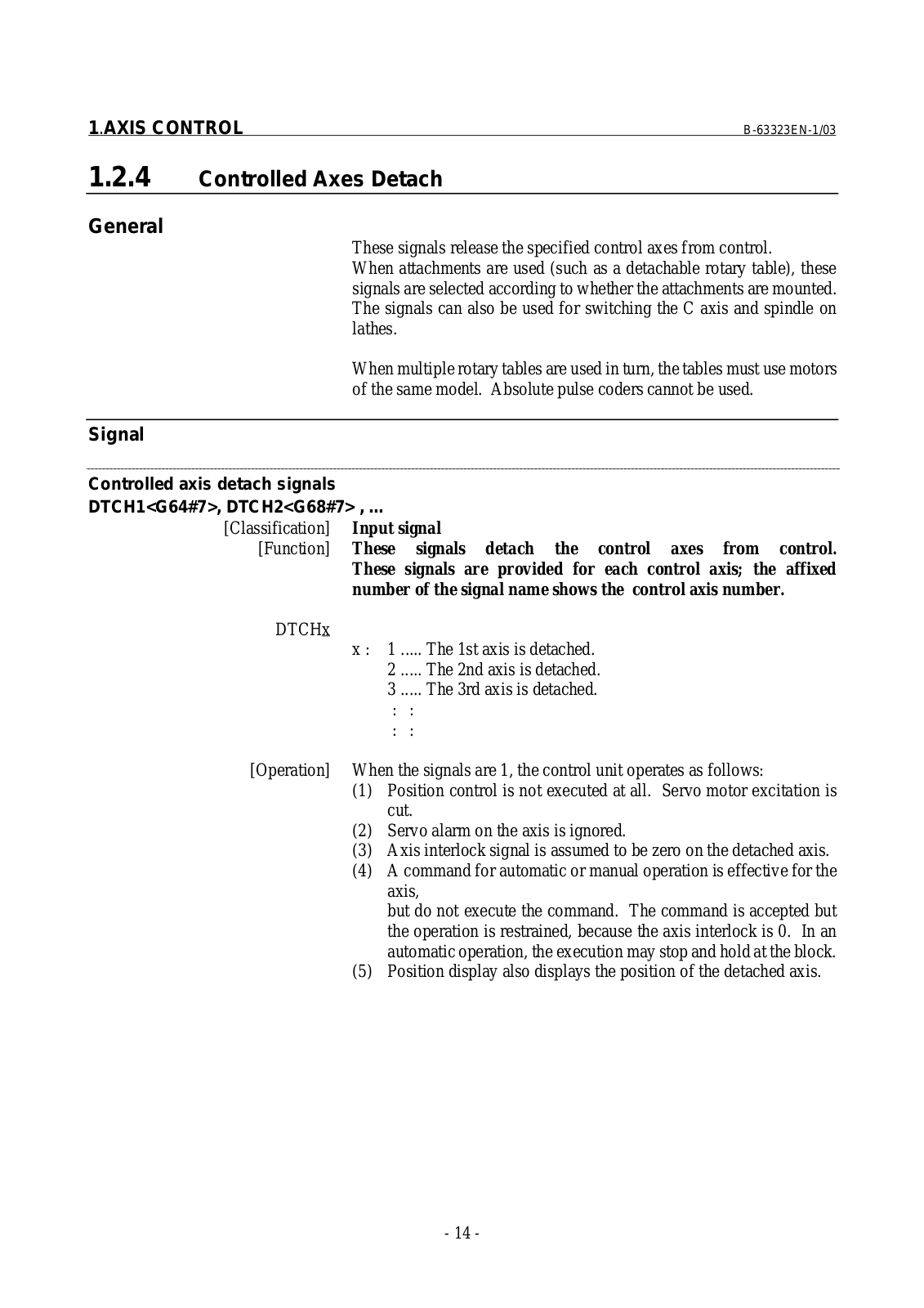
1.2.4 Controlled Axes Detach

General

These signals release the specified control axes from control.

When attachments are used (such as a detachable rotary table), these signals are selected according to whether the attachments are mounted. The signals can also be used for switching the C axis and spindle on lathes.

When multiple rotary tables are used in turn, the tables must use motors of the same model. Absolute pulse coders cannot be used.

Signal

Controlled axis detach signals

DTCH1<G64#7>, DTCH2<G68#7> , ...

[Classification]

Input signal

[Function]

These

signals detach the control axes from control.


These signals are provided for each control axis; the affixed


number of the signal name shows the control axis number.

DTCHx


x :

1 ..... The 1st axis is detached.


2 ..... The 2nd axis is detached.


3 ..... The 3rd axis is detached.


:

:


:

:

[Operation]

When the signals are 1, the control unit operates as follows:


(1)

Position control is not executed at all. Servo motor excitation is


cut.


(2)

Servo alarm on the axis is ignored.


(3)

Axis interlock signal is assumed to be zero on the detached axis.


(4)

A command for automatic or manual operation is effective for the


axis,


but do not execute the command. The command is accepted but


the operation is restrained, because the axis interlock is 0. In an


automatic operation, the execution may stop and hold at the block.


(5)

Position display also displays the position of the detached axis.

- 14 -

Loading...
+ 607 hidden pages