

Page 1
SERVICE MANUAL
RevisionE Color Ink jet Printer
EPSON WF-R8590
EPSON WF-R8591
EPSON WF-R8593
CONFIDENTIAL
SEMF14-006
Page 2

Notice:
All rights reserved. No part of this manual may be reproduced, stored in a retrieval system, or transmitted in any form or
by any means, electronic, mechanical, photocopying, recording, or otherwise, without the prior written permission of
SEIKO EPSON CORPORATION.
All effort have been made to ensure the accuracy of the contents of this manual. However, should any errors be
detected, SEIKO EPSON would greatly appreciate being informed of them.
The contents of this manual are subject to change without notice.
The above not withstanding SEIKO EPSON CORPORATION can assume no responsibility for any errors in this
manual or the consequences thereof.
EPSON is a registered trademark of SEIKO EPSON CORPORATION.
Note :Other product names used herein are for identification purpose only and may be trademarks or registered
trademarks of their respective owners. EPSON disclaims any and all rights in those marks.
Copyright © 2016 SEIKO EPSON CORPORATION
Printer CS Quality Assurance Department
Confidential
Page 3

Safety Precautions
All safety procedures described here shall be strictly adhered to by all parties servicing and maintaining this
product.
DANGER
Strictly observe the following cautions. Failure to comply could result in serious bodily injury or loss of life.
1. Always disconnect the product from the power source and peripheral devices when servicing the product or
performing maintenance.
2. When performing works described in this manual, do not connect to a power source until instructed to do so.
Connecting to a power source causes high voltage in the power supply unit and some electronic components
even if the product power switch is off. If you need to perform the work with the power cable connected to a
power source, use extreme caution to avoid electrical shock.
WARNING
Strictly observe the following cautions. Failure to comply may lead to personal injury or loss of life.
1. Always wear protective goggles for disassembly and reassembly to protect your eyes from ink in working. If
any ink gets in your eyes, wash your eyes with clean water and consult a doctor immediately.
2. When using compressed air products; such as air duster, for cleaning during repair and maintenance, the use
of such products containing flammable gas is prohibited.
PRECAUTIONS
Strictly observe the following cautions. Failure to comply may lead to personal injury or damage of the product.
1. Repairs on Epson product should be performed only by an Epson certified repair technician.
2. No work should be performed on this product by persons unfamiliar with basic safety knowledge required for
electrician.
3. The power rating of this product is indicated on the serial number/rating plate. Never connect this product to
the power source whose voltages is different from the rated voltage.
4. Replace malfunctioning components only with those components provided or approved by Epson;
introduction of second-source ICs or other non-approved components may damage the product and void any
applicable Epson warranty.
5. In order to protect sensitive microprocessors and circuitry, use static discharge equipment, such as anti-static
wrist straps, when accessing internal components.
6. Do not tilt this product immediately after initial ink charge, especially after performing the ink charge several
times. Doing so may cause ink to leak from the product because it may take some time for the waste ink pads
to completely absorb ink wasted due to the ink charge.
7. Never touch the ink or wasted ink with bare hands. If ink comes into contact with your skin, wash it off with
soap and water immediately. If you have a skin irritation, consult a doctor immediately.
Confidential
Page 4

8. When disassembling or assembling this product, make sure to wear gloves to avoid injuries from metal parts
with sharp edges.
9. Use only recommended tools for disassembling, assembling or adjusting the printer.
10. Observe the specified torque when tightening screws.
11. Be extremely careful not to scratch or contaminate the following parts.
Nozzle plate of the print head
CR Scale
PF Scale
ASF Scale
Coated surface of the PF Roller
Gears
Rollers
LCD
Scanner Sensor
Exterior parts
12. Never use oil or grease other than those specified in this manual. Use of different types of oil or grease may
damage the component or give bad influence on the printer function.
13. Apply the specified amount of grease described in this manual.
14. Make the specified adjustments when you disassemble the printer.
15. When cleaning this product, follow the procedure described in this manual.
16. When transporting this product after filling the ink in the print head, pack the printer without removing the
ink pack in order to prevent the print head from drying out. In addition, make sure to secure the CR Unit with
tape before packing the printer "5.2 Protection for Transportation (p330)".
17. Make sure to install antivirus software in the computers used for the service support activities.
18. Keep the virus pattern file of antivirus software up-to-date.
Confidential
Page 5

About This Manual
This manual, consists of the following chapters, is intended for repair service personnel and includes information
necessary for properly performing maintenance and servicing the product.
CHAPTER 1. TROUBLESHOOTING
Describes the step-by-step procedures for the troubleshooting.
CHAPTER 2. DISASSEMBLY / REASSEMBLY
Describes the disassembly/reassembly procedures for main parts/units of the product, and provides the
standard operation time for servicing the product.
CHAPTER 3. ADJUSTMENT
Describes the required adjustments for servicing the product.
CHAPTER 4. MAINTENANCE
Describes maintenance items and procedures for servicing the product.
CHAPTER 5. APPENDIX
Provides the following additional information for reference:
• Connector Diagram
• Protection for Transportation
Symbols Used in this Manual
Various symbols are used throughout this manual either to provide additional information on a specific topic or
to warn of possible danger present during a procedure or an action. Pay attention to all symbols when they are
used, and always read explanation thoroughly and follow the instructions.
Indicates an operating or maintenance procedure, practice or condition that, if not strictly observed,
could result in serious injury or loss of life.
Indicates an operating or maintenance procedure, practice, or condition that, if not strictly observed,
could result in bodily injury, damage or malfunction of equipment.
May indicate an operating or maintenance procedure, practice or condition that is necessary to
accomplish a task efficiently. It may also provide additional information that is related to a specific
subject, or comment on the results achieved through a previous action.
Confidential
Page 6

Revision Status
Revision Date of Issue Description
A July 8th, 2014 First Release
B Jan.9h, 2015 Revise content
Chapter 1
1.1.1 Troubleshooting Workflow
1.2 Power-On Sequence
1.3 Fatal Error Code List
Chapter 2
2.1.3 Standard Operation Time for servicing the product
2.3.5.4 Main Board
2.3.6.1 Print Head
2.3.6.16 Cap Unit
2.3.7.6 PF Tension Stopper
2.3.7.7 PF Tension Belt
2.3.7.8 PF Motor Assy
2.3.7.13 Sheet Guide
2.3.8.6 Ink Supply CL Assy
2.3.8.9 Tube
Chapter 3
3.2.1.1 PF Timing Belt Tension Measurement
3.2.1.3 ASF Timing Belt Tension Measurement
3.2.3 Ink Leak Check
3.2.3.2 Ink Lake Measurement jig 1
3.2.4 Head Angular Mecha Adjustment
3.2.5 SMAP Run out Adjustment
Chapter 4
4.3 Initialization of Password
C Jun 20,2015
Revise Content
Chapter 1
Fatal Error Code List (p18)
Chapter 2
Disassembly and Assembly Procedure (p59)
Chapter 3
3-3 Required Adjustment List (Adjustment using the Adjustment Program) (2/2) (p275)
Chapter 4
Firmware Update (p317)
Initialization of Password (p318)
Confidential
Page 7

Revision Date of Issue Description
D Dec. 15.2015 Chapter 2
2.1.1 Tools (p.40)
2.1.1.1 Screw types used in the printer (p.41)
2.1.2 Standard Operation Time for servicing the product (p.42)
2.3.1.2 Ink flushing (p.61- p.62)
2.3.1.3 Initial Ink charge (p.62)
2.3.3.14 Front Housing (p.80)
2.3.5.3 Main Board Unit (p.99 - p.101)
2.3.5.8 Power Supply Unit (p.110 - p.111)
2.3.6.1 Print Head (p.113, p.114)
2.3.6.2 CR Waste Ink Pad (p.116)
2.3.6.3 CR Scale
How to install the CR Scale (p.119)
2.3.6.4 PW Sensor (p.120, p.120)
2.3.6.5 Head FFC p.121 - p.127)
2.3.6.7 Taking the ink tubes from the ink supply unit. (p.130 - p.130)
2.3.6.8 CR Unit (p.131, p.131 - p.133)
2.3.6.15 Ink Supply Unit (p.145, p.145 - p.148)
2.3.8.5 Ink Supply BK Assy (p.186)
2.3.8.6 Ink Supply CL Assy (p.188)
2.3.8.7 Ink Pack Holder (BK) (p.192)
2.3.8.8 Ink Pack Holder (Y/M/C) (p.193)
2.3.8.9 Ink Tube (p.194)
2.3.13 Mechanism Unit (p.260)
Chapter 5
5.2.2 Protection of the Ink Supply Needle (p.314)
E Apr. 4.2016 Copyright (p.2)
Chapter 1
Printer fatal error list 0x8A (p.22)
Chapter 2
2.3.1 Preparation for servicing (p.61)
2.3.2.1 Maintenance Box. (p.64)
Chapter 3
Table 3-1 Required Adjustment List (Mechanism adjustment) (p.280)
Table 3-2 Required Adjustment List (Adjustment using the Adjustment Program) (1/2) (p.281)
Table 3-3 Required Adjustment List (Adjustment using the Adjustment Program) (2/2) (p.282)
3.2.4 Head Angular Mecha Adjustment
1.Turn the printer on... (p.306)
12.Turn the printer on... (p.307)
3.2.6 Inspection Mode (p.316)
3.2.6.2 Printer Inspection Mode (p.317)
Confidential
Page 8

Revision Date of Issue Description
F May 24, 2016 Revise the contents.
Chapter 2
Made change description of the disassembly/reassembly procedure in "2.3.6.1 Print
Head (p114)".
Made change description of the disassembly/reassembly procedure in "2.3.6.15 Ink
Supply Unit (p148)".
"2.3.6.19 Print Head / Ink Supply Unit (When the printer cannot perform Ink Flushing
by fatal error) (p168)" is added newly.
Chapter 3
Made change the description of Caution Box in "3.2.2.3 PG adjustment procedure
(p293)".
New procedure is added, and changing the description in "3.2.3 Ink Leak Check
(p296)".
Confidential
Page 9

EPSON WF-R8590 Revision F
Contents
Chapter 1 Troubleshooting
1.1 Troubleshooting....................................................................................................................................................... 14
1.1.1 Troubleshooting Workflow ............................................................................................................................ 14
1.2 Power-On Sequence ................................................................................................................................................ 17
1.3 Fatal Error Code List ............................................................................................................................................... 20
1.3.1 FAX Troubleshooting ..................................................................................................................................... 32
1.3.1.1 FAX Log ................................................................................................................................................ 32
1.3.1.2 Error Code/Superficial Phenomenon-Based Troubleshooting .............................................................. 37
Chapter 2 DISASSEMBLY/REASSEMBLY
2.1 Overview ................................................................................................................................................................. 40
2.1.1 Tools ............................................................................................................................................................... 40
2.1.1.1 Screw types used in the printer .............................................................................................................. 41
2.1.2 Standard Operation Time for servicing the product ....................................................................................... 42
2.2 Parts Diagram .......................................................................................................................................................... 45
2.3 Disassembly and Assembly Procedure.................................................................................................................... 61
2.3.1 Preparation for servicing ................................................................................................................................ 61
2.3.1.1
2.3.1.2 Ink flushing ............................................................................................................................................ 62
2.3.1.3 Initial Ink charge .................................................................................................................................... 63
2.3.2 Consumables/Accessories .............................................................................................................................. 64
2.3.2.1 Maintenance Box ................................................................................................................................... 64
2.3.3 Housing........................................................................................................................................................... 65
2.3.3.1 Front Cover Assy ................................................................................................................................... 65
2.3.3.2 Paper Support Support ........................................................................................................................... 66
2.3.3.3 Stacker Assy .......................................................................................................................................... 66
2.3.3.4 Rear ASF Document Support Cover ..................................................................................................... 67
2.3.3.5 Left ADF Hinge Cover .......................................................................................................................... 67
2.3.3.6 Right ADF Hinge Cover ........................................................................................................................ 68
2.3.3.7 Paper Support......................................................................................................................................... 69
2.3.3.8 Panel Assy.............................................................................................................................................. 70
2.3.3.9 Speaker................................................................................................................................................... 71
2.3.3.10 Front Cover Microswitch ..................................................................................................................... 72
2.3.3.11 Right Upper Front Cover ..................................................................................................................... 73
2.3.3.12 Panel Lower Front Cover..................................................................................................................... 73
2.3.3.13 Panel FFC ............................................................................................................................................ 74
2.3.3.14 Front Housing ...................................................................................................................................... 75
2.3.3.15 Middle Housing ................................................................................................................................... 86
2.3.4 Cover Sensors ................................................................................................................................................. 92
2.3.4.1 Rear Cover Microswitch........................................................................................................................ 92
2.3.4.2 Rear Cover PF Sensor ............................................................................................................................ 93
2.3.4.3 Right Pick Up Roller Sensor.................................................................................................................. 94
2.3.4.4 Left Pick Up Roller Sensor.................................................................................................................... 95
2.3.4.5 Casette Microswitch .............................................................................................................................. 95
2.3.4.6 PE Sensor ............................................................................................................................................... 96
2.3.5 Electric Circuit Components .......................................................................................................................... 97
2.3.5.1 USB/FAX Cover .................................................................................................................................... 97
2.3.5.2 USB Connector Assy ............................................................................................................................. 98
2.3.5.3 Main Board Unit .................................................................................................................................... 99
Unlocking the CR Unit ......................................................................................................................... 61
9
Confidential
Page 10

EPSON WF-R8590 Revision F
2.3.5.4 Main Board .......................................................................................................................................... 107
2.3.5.5 Interface Board .................................................................................................................................... 108
2.3.5.6 Wireless LAN Module ......................................................................................................................... 109
2.3.5.7 CSIC Board (BK)................................................................................................................................. 110
2.3.5.8 Power Supply Unit ............................................................................................................................... 111
2.3.6 Carriage Mechanism/ Ink System Mechanism............................................................................................. 114
2.3.6.1 Print Head ............................................................................................................................................ 114
2.3.6.2 CR Waste Ink Pad ................................................................................................................................ 119
2.3.6.3 CR Scale .............................................................................................................................................. 120
2.3.6.4 PW Sensor............................................................................................................................................ 123
2.3.6.5 Head FFC ............................................................................................................................................. 124
2.3.6.6 CR Motor ............................................................................................................................................. 131
2.3.6.7 Taking the ink tubes from the ink supply unit. ...................................... ... ... ... .... ... ... ... ... .... .. 133
2.3.6.8 CR Unit ................................................................................................................................................ 134
2.3.6.9 Decompression Motor Assy................................................................................................................. 141
2.3.6.10 APG Gear Assy.................................................................................................................................. 142
2.3.6.11 APG Sensor........................................................................................................................................ 143
2.3.6.12 APG Motor Assy ............................................................................................................................... 144
2.3.6.13 CR Solenoid Assy .............................................................................................................................. 146
2.3.6.14 Ink End Board .................................................................................................................................... 147
2.3.6.15 Ink Supply Unit.................................................................................................................................. 148
2.3.6.16 Cap Unit ............................................................................................................................................. 157
2.3.6.17 Pump Unit .......................................................................................................................................... 164
2.3.6.18 Waste Ink Joint Tube Assy ................................................................................................................ 166
2.3.6.19 Print Head / Ink Supply Unit
(When the printer cannot perform Ink Flushing by
fatal error) ......................................................................................................................................................... 168
2.3.7 Paper Feed Mechanism................................................................................................................................. 174
2.3.7.1 Rear Cover Assy/Rear Cover Belt ....................................................................................................... 174
2.3.7.2 Rear Cover Control Lever.................................................................................................................... 174
2.3.7.3 Duplex Unit.......................................................................................................................................... 175
2.3.7.4 PF Encoder Sensor Assy ...................................................................................................................... 175
2.3.7.5 Pick Up Roller Motor Assy ................................................................................................................. 176
2.3.7.6 PF Tension Stopper.............................................................................................................................. 178
2.3.7.7 PF Timing Belt..................................................................................................................................... 179
2.3.7.8 PF Motor Assy ..................................................................................................................................... 181
2.3.7.9 PE Sensor ............................................................................................................................................. 182
2.3.7.10 PF Sensor ........................................................................................................................................... 186
2.3.7.11 Star Wheel Assy................................................................................................................................. 187
2.3.7.12 Rear ASF Unit ................................................................................................................................... 188
2.3.7.13 Sheet Guide ........................................................................................................................................ 190
2.3.7.14 Rear ASF Solenoid Assy ................................................................................................................... 191
2.3.7.15 Rear ASF Solenoid Gear Assy........................................................................................................... 192
2.3.7.16 Rear ASF PE Sensor .......................................................................................................................... 193
2.3.8 Ink Supply Mechanism......................................................................................................
2.3.8.1 Ink Supply BK Cover Assy ................................................................................................................. 195
2.3.8.2 Ink Supply CL Cover Assy ................................................................................................................. 197
2.3.8.3 Ink Supply BK Cover Open Sensor..................................................................................................... 199
2.3.8.4 Ink Supply CL Cover Open Sensor ..................................................................................................... 200
2.3.8.5 Ink Supply BK Assy ............................................................................................................................ 201
2.3.8.6 Ink Supply CL Assy............................................................................................................................. 203
2.3.8.7 Ink Pack Holder (BK) .......................................................................................................................... 207
2.3.8.8 Ink Pack Holder (Y/M/C) .................................................................................................................... 208
2.3.8.9 Tube ..................................................................................................................................................... 209
2.3.8.10 CSIC FFC .......................................................................................................................................... 211
2.3.8.11 Relay FFC (BK) ................................................................................................................................. 213
2.3.8.12 Relay FFC (CL) ................................................................................................................................. 214
2.3.9 ADF/ Scanner Unit ....................................................................................................................................... 216
2.3.9.1 ADF/ Scanner Unit .............................................................................................................................. 216
2.3.9.2 ADF Unit ............................................................................................................................................. 218
........................... 195
10
Confidential
Page 11

EPSON WF-R8590 Revision F
2.3.9.3 ADF Cover Assy.................................................................................................................................. 221
2.3.9.4 Rear ADF Cover/ Rear Sub ADF Cover ............................................................................................. 222
2.3.9.5 Front Sub ADF Cover/ Front Main ADF Cover .................................................................................. 223
2.3.9.6 Document Cover Mat Assy.................................................................................................................. 225
2.3.9.7 ADF Pad Assy ..................................................................................................................................... 225
2.3.9.8 ADF Cover Microswitch ..................................................................................................................... 226
2.3.9.9 ADF PF Encoder Sensor ...................................................................................................................... 227
2.3.9.10 ADF LD Assy .................................................................................................................................... 229
2.3.9.11 ADF PF Support Guide...................................................................................................................... 231
2.3.9.12 ADF Side Cover/ ADF Paper End Side Cover .................................................................................. 232
2.3.9.13 ADF PE Sensor A .............................................................................................................................. 233
2.3.9.14 ADF PW Sensor A............................................................................................................................. 235
2.3.9.15 ADF PW Sensor B ............................................................................................................................. 236
2.3.9.16 ADF Document Detection Sensor A ................................................................................................. 237
2.3.9.17 ADF Document Detection Sensor B.................................................................................................. 238
2.3.9.18 Right ADF Hinge ............................................................................................................................... 239
2.3.9.19 Left ADF Hinge ................................................................................................................................. 240
2.3.9.20 Top ADF Document Support Assy.................................................................................................... 241
2.3.9.21 Bottom ADF Document Support ....................................................................................................... 243
2.3.10 Cassette ....................................................................................................................................................... 244
2.3.10.1 Casette Assy....................................................................................................................................... 244
2.3.10.2 Casette End Guide ............................................................................................................................. 244
2.3.11 2nd Cassette................................................................................................................................................ 245
2.3.11.1 2nd Cassette Unit ............................................................................................................................... 245
2.3.11.2 2nd Cassette Assy .............................................................................................................................. 247
2.3.11.3 2nd Cassette Frame Assy................................................................................................................... 247
2.3.11.4 2nd Cassette Drive Assy .................................................................................................................... 251
2.3.11.5 Actuator ............................................................................................................................................. 253
2.3.11.6 Sensor................................................................................................................................................. 254
2.3.11.7 Feed Roller......................................................................................................................................... 256
2.3.12 Option Cassette ........................................................................................................................................... 257
2.3.12.1 OP Casette Unit ................................................................................................................................. 257
2.3.12.2 OP Cassette Assy ............................................................................................................................... 258
2.3.12.3 OP Casette Retard Roller Assy.......................................................................................................... 258
2.3.12.4 OP Cassette End Guide...................................................................................................................... 259
2.3.12.5 OP Cassette Edge Guide Right .......................................................................................................... 259
2.3.12.6 OP Rear Cover Assy .......................................................................................................................... 261
2.3.12.7 Stopper Belt ....................................................................................................................................... 261
2.3.12.8 OP Right Cover.................................................................................................................................. 262
2.3.12.9 OP Left Cover.................................................................................................................................... 262
2.3.12.10 OP Rear Frame Assy........................................................................................................................ 263
2.3.12.11 OP Cassette Drive Assy................................................................................................................... 266
2.3.12.12 OP Rear Cover Open Microswitch .................................................................................................. 268
2.3.12.13 OP Rear Frame Cover Assy............................................................................................................. 268
2.3.12.14 OP Cassette Microswitch................................................................................................................. 271
2.3.12.15 OP Cassette PF Sensor..................................................................................................................... 272
2.3.12.16 OP Cassette Paper Sensor ................................................................................................................ 273
2.3.12.17 OP Cassette Hopper Sensor ............................................................................................................. 274
2.3.13 Mechanism Unit ......................................................................................................................................... 275
2.4 Routing the cables and FFC .................................................................................................................................. 277
2.4.1 Around the Main Board................................................................................................................................ 277
Chapter 3 Adjustment
3.1 Required Adjustments ........................................................................................................................................... 279
3.2 Details of Adjustments .......................................................................................................................................... 283
3.2.1 PF/CR/ASF Timing Belt Tension Measurement .......................................................................................... 283
3.2.1.1 PF Timing Belt Tension Measurement ................................................................................................ 284
3.2.1.2 CR Timing Belt Tension Check........................................................................................................... 286
11
Confidential
Page 12

EPSON WF-R8590 Revision F
3.2.1.3 ASF Timing Belt Tension Measurement ............................................................................................. 287
3.2.2 PG Adjustment ............................................................................................................................................. 289
3.2.2.1 PG Adjustment procedure.................................................................................................................... 289
3.2.2.2 Preparation ........................................................................................................................................... 290
3.2.2.3 PG adjustment procedure ..................................................................................................................... 293
3.2.2.4 Checking the Platen Gap...................................................................................................................... 295
3.2.3 Ink Leak Check............................................................................................................................................. 296
3.2.3.1 Method of using the Leakage Check PET Chip. ................................................................................. 296
3.2.3.2 Method of using the Ink Leak Measurement jig.................................................................................. 298
3.2.4 Head Angular Mecha Adjustment ................................................................................................................ 306
3.2.5 SMAP Run out Adjustment .......................................................................................................................... 309
3.2.6 Inspection Mode ........................................................................................................................................... 316
3.2.6.1 To enter Inspection Mode................................................................................................... 316
3.2.6.2 Printer Inspection Mode....................................................................................................... 317
3.2.6.3 Touch Panel Adjustment...................................................................................................................... 318
3.2.6.4 To exit the Inspection Mode: ............................................................................................................... 321
Chapter 4 Maintenance
4.1 Overview ............................................................................................................................................................... 323
4.1.1 Cleaning ........................................................................................................................................................ 323
4.1.2 Lubrication.................................................................................................................................................... 323
4.2 Lubrication Points and Instructions....................................................................................................................... 324
4.3 Firmware Update ................................................................................................................................................... 326
4.4 Initialization of Password...................................................................................................................................... 327
Chapter 5 Appendix
5.1 Revision FConnector Diagram.............................................................................................................................. 329
5.2 Protection for Transportation ................................................................................................................................ 330
5.2.1 Securing the CR Unit.................................................................................................................................... 330
5.2.2 Protection of the Ink Supply Needle............................................................................................................. 331
12
Confidential
Page 13

CHAPTER 1
TROUBLESHOOTING
Confidential
Page 14
EPSON WF-R8590/WF-R8591/WF-R8593
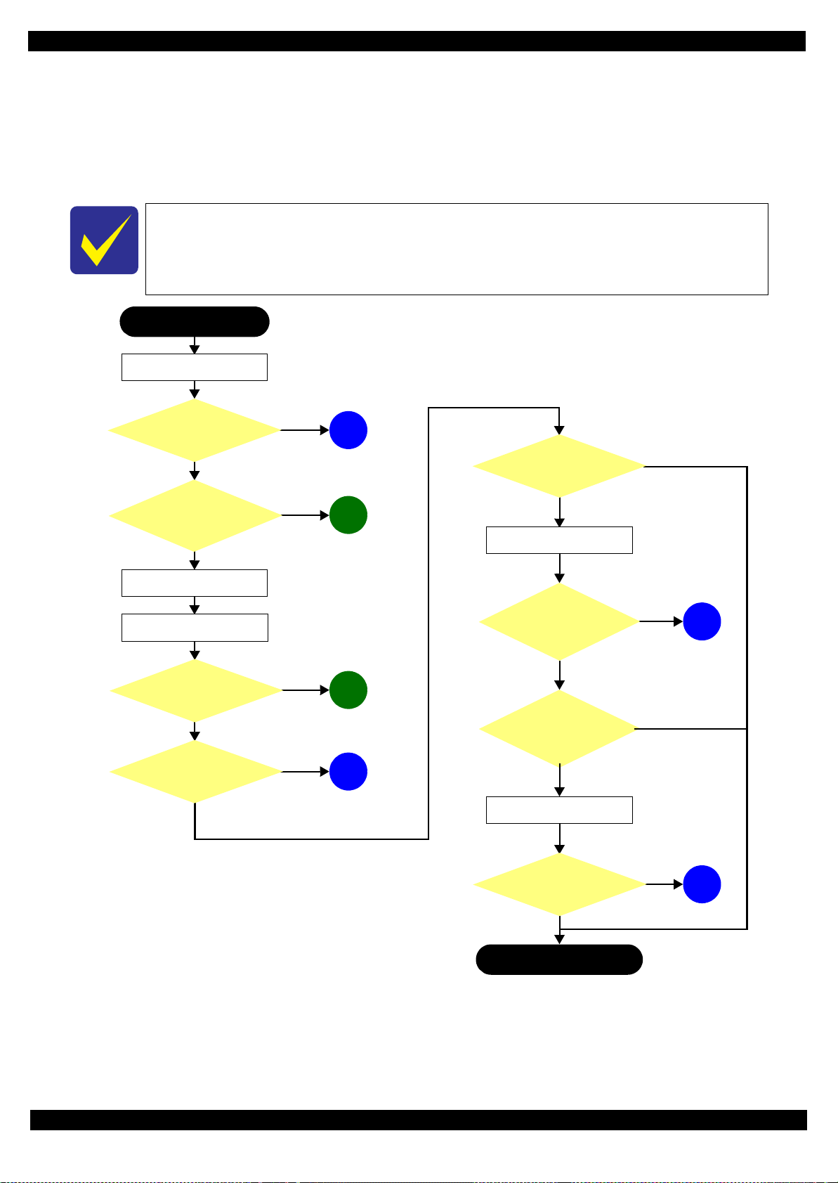
ADF failure?
Finish
*
Turn on the printer
2
What is returned reason?
Copy an image
Copy an image by ADF
Start
ADF/Scanner
unit failure
Printer failure only
Yes
Yes
Yes
No
Does printer turn on the
power?
Yes
Is Power-on sequence
finished without error?
Yes
No
Is ADF operation finished
without trouble?
Standby condition
Is scanning operation
finished without
trouble?
1
No
Print check pattern
Is printing operation
finished without trouble?
Yes
Yes
Is printing operation
finished without error?
4
No
3
No
5
No
6
No
*: In case of “Not Trouble Found”, check fatal error code.
(p15)
(p15)
(p15)
(p16)
(p16)
(p16)
1.1 Troubleshooting
This section describes the troubleshooting workflow.
1.1.1 Troubleshooting Workflow
The following page describes the troubleshooting workflow. Follow the flow when troubleshooting problems.
This flowchart is compiled based on the following contents.
• Our experience regarding the quality problem.
• Printer Mechanism specification for WF-R8590,WF-R8591 and WF-R8593.
When FAX related error occurs, see " 1.3.1 FAX Troubleshooting (p32)".
Revision F
Troubleshooting Troubleshooting 14
Figure 1-1. Troubleshooting Workflow (1)
Confidential
Page 15

EPSON WF-R8590/WF-R8591/WF-R8593 Revision F
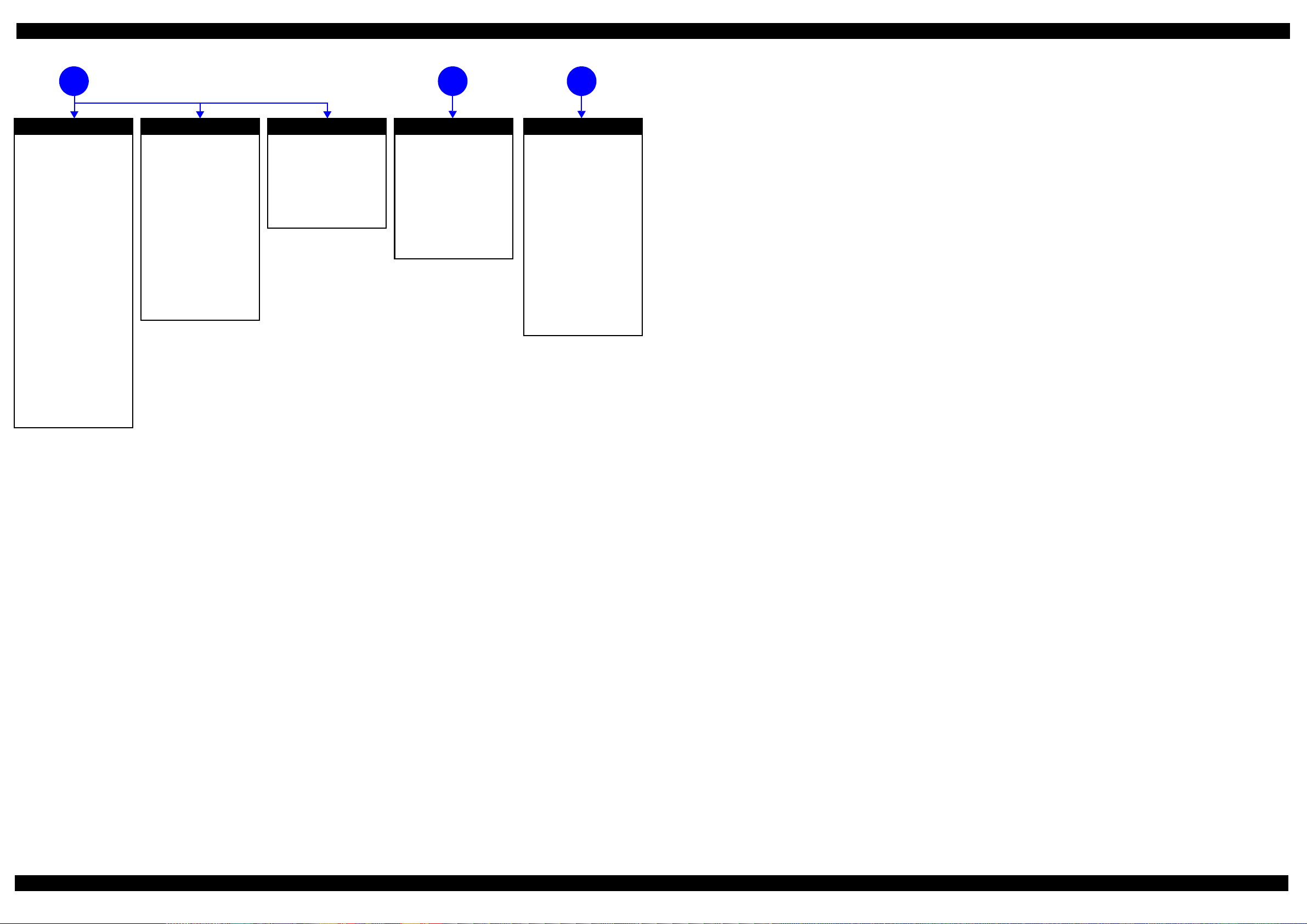
The power-on
1
sequence does not
start (p14)
No Power
[Presumable Cause]
• AC cable is unplugged.
• Power shuts down due to
scanner error.
• Power Supply Unit damage
• Main Board damage
• Detection failure of PW Sensor
occurred at power-on.
[Major Troubleshooting]
• Plug AC cable.
• Connect scanner harness.
• Power Supply Unit
replacement
• Main Board replacement
*
*: If the printer can turn on but turns off right away,
the protection circuit may cut off the power due to
an error such as a circuit failure.
Error is indicated during printing nozzle check pattern (p14)
3
LEDs on panel are flashing
[Presumable Cause]
• Wi-Fi connector is unplugged
• Wi-Fi Board damage
[Major Troubleshooting]
• Plug Wi-Fi connector
• Wi-Fi Board replacement
Error is indicated during
2
power-on sequence (p14)
Fatal error
Please refer to
List (p20)"
" 1.3 Fatal Error Code
for troubleshooting.
CR Fixing Tape error
[Occurrence Condition]
This error occurs if a paper jam
occurs during the power-on
sequence before initial ink charge.
[Major Occurrence Timing]
Power-on timing
(before initial ink charge)
[Major Troubleshooting]
Open the front cover and remove
the CR fixing tape.
Maintenance error
[Occurrence Condition]
This error occurs when
maintenance counter in EEPROM
exceeds the specified value.
[Major Occurrence Timing]
• Power-on timing
• Print start timing
• Paper eject timing
• Cleaning timing
• Ink pack replacement timing
[Major Troubleshooting]
• Replace Maintenance Box
No Maintenance Box error
[Occurrence Condition]
This error occurs when
Maintenance Box is not installed.
[Major Occurrence Timing]
• At power-on
• Maintenance Box monitoring
timing
[Major Troubleshooting]
• Turn the printer off once and
install Maintenance Box again,
and turn the power on.
Maintenance Box detection
[Occurrence Condition]
This error occurs when
Maintenance Box data is incorrect
or it is not recognized correctly.
[Major Occurrence Timing]
• Power-on timing
• Maintenance Box replacement
• Maintenance Box monitoring
[Major Troubleshooting]
• Remove and reinstall
• Maintenance Box replacement
• Relay Board CSIC Terminal
• Relay Board Assy replacement
• Relay Board FFC replacement
• Main Board replacement
error
timing
timing
Maintenance Box
replacement
Ink End error
[Occurrence Condition]
This error occurs when ink in Ink
pack is empty.
[Major Occurrence Timing]
• Power-on timing
• Print start timing
• Print timing
• Cleaning timing
• Ink pack replacement timing
[Major Troubleshooting]
Ink pack replacement
[NOTE]
If an error occurs during
printing, the page where the error
occurred is skipped and the
printing resumes from the next
page.
Ink pack detection error
[Occurrence Condition]
This error occurs when Ink pack
data is incorrect or Ink pack is not
recognized correctly.
[Major Occurrence Timing]
• Power-on timing
• Print start timing
• Cleaning timing
• Ink pack replacement timing
[Major Troubleshooting]
• Remove and reinstall Ink pack.
• Ink pack replacement
• CSIC Terminal replacement
• CSIC FFC replacement
• CR Contact Module
replacement
• Main Board replacement
No Ink pack error
[Occurrence Condition]
This error occurs when Ink pack
not installed.
[Major Occurrence Timing]
At power-on
[Major Troubleshooting]
Install Ink pack
Paper Jam error
Please refer to " Paper Jam error".
Cover open error
[Occurrence Condition]
This error occurs when Scanner
Unit (Printer Cover) is open.
[Major Occurrence Timing]
• At power-on
• During printing
[Major Troubleshooting]
• Close Scanner Unit (Printer
Cover) replacement
• Scanner Unit (Printer Cover)
replacement
• Cover Open Sensor
replacement
• Main Board replacement
Paper Jam error
[Occurrence Condition]
This error occurs when top/
bottom of paper is not detected by
PE Sensor or PW Sensor in the
specified steps of paper feeding
operation correctly.
[Major Occurrence Timing]
• Power-on timing
• Paper loading timing
• Paper eject timing
• Duplex print timing
[Major Troubleshooting]
1 Remove the jammed paper by
opening Printer Cover.
2 Push “Start” button.
3 If not resolved by 2), check the
following.
• Foreign material, bits of
paper
• Part come-off
• PE Lever
•PE Sensor
• Main Board
•PW Sensor
[NOTE]
* If an error occurs during
printing, the page where the error
occurred is skipped and the
printing resumes from the next
page.
* If an error occurs during duplex
printing, the following are
performed.
• If an error occurs during the
front face of duplex printing,
the page where the error
occurred and the next page
are skipped and the printing
resumes from the page after
the next.
• If an error occurs during the
back face of duplex printing,
the page where the error
occurred is skipped and the
printing resumes from the
next page.
No Paper error
[Occurrence Condition]
This error occurs when top of
paper is not detected by PE Sensor
in the specified steps of paper
loading operation correctly.
[Major Occurrence Timing]
Paper loading timing
[Major Troubleshooting]
1 Put paper in cassette and push
“START” button.
2 If a paper stops before reaching
PE Sensor, remove it and
check the paper condition.
3 A) If no damage on the paper, set
edge guide correctly after
putting paper in cassette and
push “PRINT” button again.
B) If damage on the paper, check
foreign materials / parts come off / parts transformation in
paper path.
4 If not resolved by 3-A) & 3-B),
check the following.
• Pickup Roller
• Duplex Unit
•PE Sensor
• Main Board
•PF Motor
• Casette Assy
Double Feed error
[Occurrence Condition]
This error occurs on the following
cases.
• A paper is ejected without
printing during paper loading
operation.
• Actual paper length is longer
than theoretical one.
[Major Occurrence Timing]
Paper loading timing
[Major Troubleshooting]
• PE Lever replacement
• PE Sensor replacement
• PW Sensor replacement
• Main Board replacement
No Paper Cassette error
[Occurrence Condition]
This error occurs if one of the
cassettes is not installed.
[Major Occurrence Timing]
Paper loading timing
(Front loading)
[Major Troubleshooting]
Install the Cassette Assy.
Paper Size Unmatch error
[Occurrence Condition]
This error occurs when actual
paper size is not matched to
theoretical one.
[Major Occurrence Timing]
• Duplex print timing
• FAX data print timing
[Major Troubleshooting]
1 Put correct sized paper in
cassette, and push “START”
button.
2 If not resolved by step 1),
check the following points.
• PE Lever
• PE Sensor
• PW Sensor
•Main Board
Manual Tray No Paper error
[Occurrence Condition]
When printing from Manual Tray
(MSF unit), this error occurs if
paper is not loaded at the time of
data transmission.
[Major Occurrence Timing]
Paper loading timing
(Rear loading)
[Major Troubleshooting]
• Put paper in the Manual Tray
(MSF unit).
• PE Sensor replacement
• PE Lever replacement
• Main Board replacement
Manual Feed Request error
[Occurrence Condition]
This error occurs if the printer
cannot receive the manual feed
request.
[Major Occurrence Timing]
Paper loading timing
(Rear loading)
[Major Troubleshooting]
• Send the print data.
• Main Board replacement
Excessive Manual Feed Error
[Occurrence Condition]
This error occurs when the PE
Sensor detects paper before
manual feed or when paper is
inserted too much.
[Major Occurrence Timing]
Print start timing (Rear loading)
[Major Troubleshooting]
• Eject paper with panel
operation, and load paper
again.
• Main Board replacement
• PE Sensor replacement
• PE Lever replacement
Insufficient Manual Feed
[Occurrence Condition]
This error occurs during manual
feed if the PE Sensor detects
paper but the paper is not fed by
auto loading.
[Major Occurrence Timing]
Print start timing (Rear loading)
[Major Troubleshooting]
Eject paper with panel operation,
and load paper again.
error
Figure 1-2. Troubleshooting Workflow (2)
15
Confidential
Page 16
EPSON WF-R8590/WF-R8591/WF-R8593 Revision F
Problems related to print result or during printing (p14)
Poor Printing
[Phenomenon]
• Poor printing quality
• Ink stain on paper
• Dot missing
• Paper eject without printing
[Presumable Cause]
• Driver / Panel mis-setting
• Contamination of CR scale
• Contamination of Printhead
Cover
• Printhead damage
• Ink clogging of Printhead
• Contamination on Cap Unit /
Wiper of Ink system Assy
• Ink system Assy damage
• Narrow PG
• PE Lever damage
• PE Sensor damage
• PW Sensor damage
[Major Troubleshooting]
• Driver / Panel re-setting
• CR Scale replacement
• Printhead cover cleaning
• Printhead cleaning
• Ink pack replacement
• Printhead replacement
• Rubber cleaning of Cap Unit of
Ink system Assy
• Ink system Assy replacement
• PG readjustment
• Printer Mechanism
replacement
• PE Lever replacement
• PE Sensor replacement
• PW Sensor replacement
Poor Paper Loading
[Presumable Cause]
• Use of 3rd party media
• Edge guide mis-setting
• Foreign material
• Parts come-off
• Contamination of paper feed
roller (Duplex Unit)
• Cassette Assy damage
• Pickup Roller deterioration,
contamination
• Contamination of PF roller
[Major Troubleshooting]
• Recommendation of EPSON
media
• Edge guide re-setting
• Foreign material removal
• Parts re-installation
• Pick Up Assy replacement
• Cassette Assy replacement
• Printer Mechanism
replacement
• Rear ASF Unit replacement
Abnormal Noise
[Presumable Cause]
• Foreign material
• Insufficient grease
• Gear damage
• Stopper Holder Idle Roller is
installed in a wrong place.
[Major Troubleshooting]
• Foreign material removal
• Lubrication of grease
• Gear replacement
Scanning cannot
be performed
5 64
successfully (p14)
Scanner failure
[Presumable Cause]
• Contamination of Scanner
Glass
• Contamination of Document
Pad
• CIS Unit bonding failure
• CIS Unit damage
• Scanner Motor damage
[Major Troubleshooting]
• Scanner Glass cleaning
• Document Pad cleaning
• Document Pad replacement
• CIS Unit replacement
• Scanner Motor replacement
ADF does
not operate
normally
(p14)
ADF failure
[Phenomenon]
• No paper feed
• Double feed
• Paper jam
• Paper skew
[Presumable Cause]
• Wear of Pickup Roller
• Wear of ADF Pad Assy
• Gear damage
• ADF Motor damage
• Contamination of Scanner
Glass
• Foreign material
• Paper Sheet damage
• ADF Cover Assy damage
• Wear of EJ Roller
• ADF Sensors damage
[Major Troubleshooting]
• ADF Cover Assy replacement
• ADF Pad Assy replacement
• Scanner Glass cleaning
• Foreign material removal
• ADF Unit replacement
Figure 1-3. Troubleshooting Workflow (3)
16
Confidential
Page 17
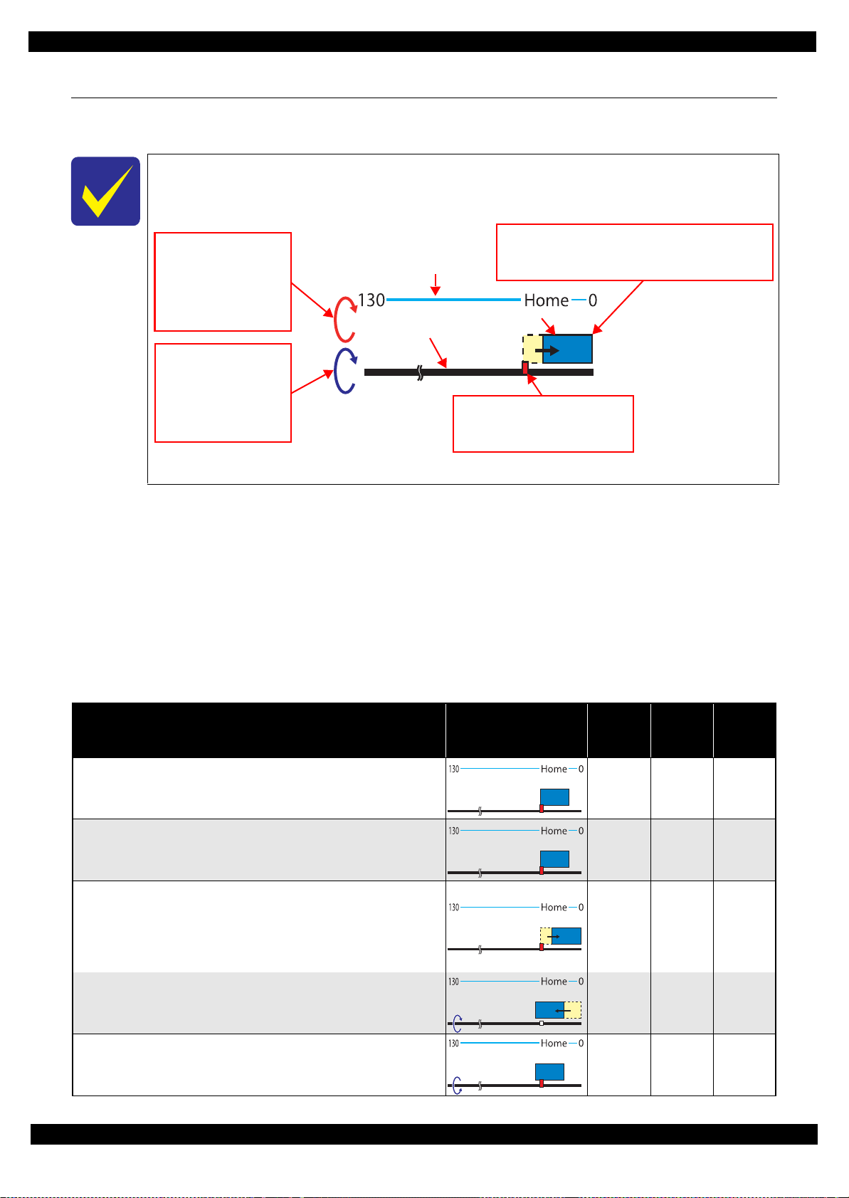
EPSON WF-R8590/WF-R8591/WF-R8593 Revision F
The condition of the CR lock
Red: CR lock is set
White: CR lock is released
The above shows the CR lock is set.
Carriage movement
Right-pointing arrow: Moves to the 0-digit side
Left-pointing arrow: Moves to the 130-digit side
The figure shows the carriage is moving to the 0-digit side.
Digit number of CR
PF Roller
Carriage
The rotation direction of
the ASF Motor
Clockwise:
Paper is fed normally
Counterclockwise:
Paper is fed backward
The above shows clockwise
rotation.
The rotation direction of
the PF Motor
Clockwise:
Paper is fed normally
Counterclockwise:
Paper is fed backward
The above shows clockwise
rotation.
1.2 Power-On Sequence
This section describes the power-on sequences for this product. The preconditions are as follows.
The following explains how to use the simplified diagrams in Table 1-1 or Table 1-2. The
diagrams show the movement of each component as seen from the front of the printer.
Figure 1-4. Movement of Components
Normal power-on sequence
No error occurred at the last power-on, and the power was turned off normally.
Initial ink charge has finished and every pack has sufficient ink.
No paper on the paper path.
The Printhead is capped by the cap of the Ink System.
CR Lock is engaged normally.
This indicates the Simple Sequence.
PG position is set to PG 1.
Option Cassette Unit is not installed.
Table 1-1. Power-on Sequence
Operation
1. APG reset
1-1.If PG is other than 1, the APG Motor rotates to set PG to 1.*
2. Printhead initialization and fuse inspection
2-1.Initializes the Printhead, and checks the fuse on the printer control
circuit board.
*1
9
Movement of
Components
CR
Motor
rotation
PF
Motor
rotation
--- --- ---
--- --- ---
ASF
Motor
rotation
3. Seeking the home position
3-1.To identify the CR Unit position, the CR Motor rotates
counterclockwise and it confirms the CR Unit touches the Right Frame
slowly. It regards the point when the CR Unit touches the Right Frame
as the position specified steps away from the home position, and sets it
as the origin.
3-2.If it judges the CR Unit is in the home position, the PF Motor rotates
clockwise and resets the CR lock.
3-3.The PF Motor rotates counterclockwise and sets the CR lock.
CCW --- ---
--- CW ---
--- CCW ---
Power-On Sequence 17
Confidential
Page 18

EPSON WF-R8590/WF-R8591/WF-R8593 Revision F
Table 1-1. Power-on Sequence
Operation
3-4.The CR Motor rotates clockwise and it confirms the CR Unit touches
the Left Frame.*
3-5.The CR Motor and PF Motor stop.
3-6.The CR Motor rotates clockwise, and the CR Unit moves to the home
position, then the CR lock is set.
3-7.The PF Motor rotates clockwise and releases the CR lock.
2
4. CR measurement
4-1.The CR Motor rotates counterclockwise, and the CR Unit moves to the
0-digit side.*
3
Movement of
Components
CR
Motor
rotation
CW --- ---
--- --- ---
CW CCW ---
--- CW ---
CCW --- ---
PF
Motor
rotation
ASF
Motor
rotation
4-2.The CR Motor rotates clockwise, and the CR Unit moves to the 130-
digit side. (Measurement drive)
5. Adjustment of CR acceleration delay
5-1.The CR Motor rotates and the CR Unit moves back and forth two
times.*
4
6. Measurement of synchronized drive timing correction
6-1.The PF Motor and ASF Motor rotate.
7. Low temperature operation sequence
7-1.The PF Motor rotates clockwise, and the CR lock is unlocked.
7-2.The CR Motor rotates and the CR Unit moves back and forth two
7-3.The PF Motor rotates counterclockwise and the CR lock is set.
times.*
4
*5
8. Setting the PF Roller origin
8-1.The PF Motor rotates clockwise.
*6
CW --- ---
CW/
CCW
---
--- ---
CW/
CCW
CCW
--- CW ---
CW/
CCW
--- ---
--- CCW ---
--- CW ---
CW/
9. Sucking supply
9-1.The Decompression Motor Assy 1 rotates in turn (decompresses =>
vents to atmosphere), and the diaphragm pump sucks ink from the ink
cartridges.*
9-2.The Decompression Motor Assy 2 rotates in turn (decompresses =>
vents to atmosphere), and the diaphragm pump sucks ink from the ink
cartridges.*
8
8
10.Ink detection
10-1.Checks the ink consumption counters and the status of ink cartridges.
Power-On Sequence 18
--- --- ---
--- --- ---
--- --- ---
Confidential
Page 19

EPSON WF-R8590/WF-R8591/WF-R8593 Revision F
Table 1-1. Power-on Sequence
Operation
11.Checking for waste ink overflow
11-1.Checks the waste ink counter of the Maintenance Box if the waste ink
overflow is occurring.
12.CR lock setting
12-1.The CR Motor rotates clockwise and the CR Unit moves to the home
position.
12-2.The CR Motor rotates counterclockwise and the CR Unit moves to the
0-digit side.
12-3.The PF Motor rotates counterclockwise and the CR lock is set.
12-4.The CR Motor rotates clockwise and the CR Unit moves to the home
position.
Movement of
Components
CR
Motor
rotation
--- --- ---
CW --- ---
CCW --- ---
--- CCW ---
CW --- ---
PF
Motor
rotation
ASF
Motor
rotation
13.Set the Hopper up
13-1.The ASF Motor rotates clockwise and the Hopper is set up.
*7
--- --- CW
Note : On the premise on this table, PG does not change and the Rear ASF does not operate during the sequence.
Note "*1": If any trouble exists such as the fuse has blown, the fatal error occurs.
"*2": At this point, if the output value of the CR Motor is below the specified value, the paper jam error occurs.
"*3": If, at this point, the output value of the CR Motor is more than the specified value, the fatal error occurs.
"*4": The DC error may occur.
o
"*5": Executes when the detected temperature is under 5
"*6": If the phase of the PF Roller cannot be detected, the SMAP phase detection error occurs.
"*7": If the sensor cannot detect the Hopper, the cassette damage error occurs.
"*8": If the Front Cover is open, the front cover open error occurs.
"*9": If the sensor cannot detect the APG position, the APG error occurs.
C (41oF) by the thermistor on the Printhead.
Power-on Sequence after Recovering from a Paper Jam Error
Table 1-2. Power-on Sequence after Recovering from a Paper Jam Error
CR
Motor
rotation
CW/
CCW
Operation
Executes No.1 on the power-on sequence (Table 1-1).
1. Detecting remaining paper
1-1.The CR Motor rotates and the CR Unit moves back and forth slowly
once.
Movement of
Components
PF
Motor
rotation
--- ---
ASF
Motor
rotation
1-2.The CR Motor rotates clockwise and the CR Unit moves to the 0-digit
side slowly. At this point, if the CR lock lever, APG lever, and Suction
Unit are on the way, it evacuates them.
1-3.The CR Motor rotates and the CR Unit moves back and forth slowly
once.*
1
CW --- ---
CW/
CCW
Note : On the premise on this table, PG does not change and the Rear ASF does not operate during the sequence.
Note *1: At this point, if the output value of the CR Motor is more than the specified value, the paper jam error occurs.
Power-On Sequence 19
--- ---
Confidential
Page 20

EPSON WF-R8590/WF-R8591/WF-R8593 Revision F
1.3 Fatal Error Code List
This section describes the fatal error code and the possible cause for this product.
Printer fatal error list
Table 1-3. Fatal Error List (Printer)
Error type
Printer
Error
code
0x60 HP (Home Potion) error
0x61 Deadlock Avoidance error
0x62 Impossible contact detection error
0x63
0x64 PW sensor failure error
0x65 PW sensor detected foreign object error
0x67 APG error
0x69 Option Cassette recovery mode error
0x6A SMAP phase detection error • Misalignment of eccentric correction phase
0x6B PF runaway error
0x6C Option Cassette Connected error • Four optional cassettes or more setting error
0x6D Option Cassette Connected error • Option cassette setting error
0x6E Option Cassette Connected error • Option cassette setting error
0x6F Option Cassette Connected error • Option cassette setting error
0x70 Opt1 ASF excess load error
0x71 Opt1 ASF excess speed error
0x72 Opt1 ASF PID reverse error
Contact error at ink replacement timing
(Power-off)
Error name Possible cause
•Paper jam
• Foreign object
• Deformation of the main frame
• Foreign object
• Lock the CR Unit.
• Deformation of the main frame
•Paper jam
• Foreign object
• PW sensor failure
• Deformation of the main frame
•Paper jam
• Foreign object
• Deformation of the main frame
• Defective initial operation
• Foreign object
• PW sensor failure
• Main board failure
• Power On Sequence error
•Paper jam
• Foreign object
• Deformation of the main frame
• APG motor failure
• APG encoder failure
• Main board failure
• Option cassette board failure
• Main board failure
• PF encoder failure
• Motor driver failure
• Opt1 ASF Encoder failure (contaminated/detached scale, Encoder
Board failure)
• Opt1 ASF motor failure
• Pickup Roller driven mechanism overload (paper jam/foreign object)
• Cable disconnection
• Opt1 ASF Encoder failure (contaminated/detached scale, Encoder
Board failure)
• Opt1 ASF motor failure
• Pickup Roller driven mechanism overload (paper jam/foreign object)
• Cable disconnection
• Opt1 ASF Encoder failure (contaminated/detached scale, Encoder
Board failure)
• Opt1 ASF motor failure
• Pickup Roller driven mechanism overload (paper jam/foreign object)
• Cable disconnection
Fatal Error Code List 20
Confidential
Page 21

EPSON WF-R8590/WF-R8591/WF-R8593 Revision F
Table 1-3. Fatal Error List (Printer)
Error type
Printer
Error
code
0x73 Opt1 ASF PID lock error
0x74 Opt1 ASF load position reverse error
0x75 Opt1 ASF load position excess speed error
0x76 Opt1 ASF load position excess load error
0x77 Opt1 LFT PID excess load error
0x78 Opt1 LFT PID excess speed error
0x79 Opt1 LFT PID lock error
0x7A Opt1 LFT PID driving time error
0x7B Opt2 LFT PID driving time error
0x7C Opt3 LFT PID driving time error
0x7D Option Communication error • Main board failure (UART Parity error/ UART FIFO Overflow)
0x7E Emergency stop error • Emergency cover open error
0x7F Inspection mode error ---
0x80 Opt2 ASF PID excess load error
0x81 Opt2 ASF PID excess speed error
Error name Possible cause
• Opt1 ASF Encoder failure (contaminated/detached scale, Encoder
Board failure)
• Opt1 ASF motor failure
• Pickup Roller driven mechanism overload (paper jam/foreign object)
• Cable disconnection
• Opt1 ASF Encoder failure (contaminated/detached scale, Encoder
Board failure)
• Opt1 ASF motor failure
• Pickup Roller driven mechanism overload (paper jam/foreign object)
• Cable disconnection
• Opt1 ASF Encoder failure (contaminated/detached scale, Encoder
Board failure)
• Opt1 ASF motor failure
• Pickup Roller driven mechanism overload (paper jam/foreign object)
• Cable disconnection
• Opt1 ASF Encoder failure (contaminated/detached scale, Encoder
Board failure)
• Opt1 ASF motor failure
• Pickup Roller driven mechanism overload (paper jam/foreign object)
• Cable disconnection
• Protection material remains
• Opt1 LFT Motor Failure
• Opt1 ASF Encoder failure (contaminated/detached scale, Encoder
Board failure)
• Opt1 LIFT driven mechanism overload (paper jam/foreign object)
• Cable disconnection
• Opt1 LFT Motor Failure
• Opt1 ASF Encoder failure (contaminated/detached scale, Encoder
Board failure)
• Opt1 LIFT driven mechanism overload (paper jam/foreign object)
• Cable disconnection
• Opt1 ASF Encoder failure (contaminated/detached scale, Encoder
Board failure)
• Opt1 ASF motor failure
• Opt1 LIFT driven mechanism overload (paper jam/foreign object)
• Cable disconnection
• Opt1 LIFT motor failure
• Opt1 LIFT driven mechanism overload (paper jam/foreign object)
• Opt2 LIFT motor failure
• Opt2 LIFT driven mechanism overload (paper jam/foreign object)
• Opt3 LIFT motor failure
• Opt3 LIFT driven mechanism overload (paper jam/foreign object)
• Opt2 ASF Encoder failure (contaminated/detached scale, Encoder
Board failure)
• Opt2 ASF motor failure
• Pickup Roller driven mechanism overload (paper jam/foreign object)
• Cable disconnection
• Opt2 ASF Encoder failure (contaminated/detached scale, Encoder
Board failure)
• Opt2 ASF motor failure
• Pickup Roller driven mechanism overload (paper jam/foreign object)
• Cable disconnection
Fatal Error Code List 21
Confidential
Page 22

EPSON WF-R8590/WF-R8591/WF-R8593 Revision F
Table 1-3. Fatal Error List (Printer)
Error type
Printer
Error
code
0x82 Opt2 ASF PID reverse error
0x83 Opt2 ASF PID lock error
0x84 Opt2 ASF load position reverse error
0x85 Opt2 ASF load position excess load error
0x86 Opt2 ASF load position excess load error
0x87 Opt2 LFT PID excess load error
0x88 Opt2 LFT PID excess speed error
0x89 Opt2 LFT PID lock error
0x8A Ink Leak error
0x8C Opt Communication error
0x8D Factor Error other than printer driver
0x8E Driver mismatch error • An unsupported drive was used.
0x8F EEPROM verify error (by command) ---
0x93 PE sensor failure
0x94 PW sensor light value adjust error
Error name Possible cause
• Opt2 ASF Encoder failure (contaminated/detached scale, Encoder
Board failure)
• Opt2 ASF motor failure
• Pickup Roller driven mechanism overload (paper jam/foreign object)
• Cable disconnection
• Opt2 ASF Encoder failure (contaminated/detached scale, Encoder
Board failure)
• Opt2 ASF motor failure
• Pickup Roller driven mechanism overload (paper jam/foreign object)
• Cable disconnection
• Opt2 ASF Encoder failure (contaminated/detached scale, Encoder
Board failure)
• Opt2 ASF motor failure
• Pickup Roller driven mechanism overload (paper jam/foreign object)
• Cable disconnection
• Opt2 ASF Encoder failure (contaminated/detached scale, Encoder
Board failure)
• Opt2 ASF motor failure
• Pickup Roller driven mechanism overload (paper jam/foreign object)
• Cable disconnection
• Opt2 ASF Encoder failure (contaminated/detached scale, Encoder
Board failure)
• Opt2 ASF motor failure
• Pickup Roller driven mechanism overload (paper jam/foreign object)
• Cable disconnection
• Protection material remains
• Opt2 LIFT motor failure
• Opt2 ASF Encoder failure (contaminated/detached scale, Encoder
Board failure)
• Opt2 LIFT driven mechanism overload (paper jam/foreign object)
• Cable disconnection
• Opt2 LIFT motor failure
• Opt2 ASF Encoder failure (contaminated/detached scale, Encoder
Board failure)
• Opt2 LIFT driven mechanism overload (paper jam/foreign object)
• Cable disconnection
• Opt2 LIFT motor failure
• Opt2 ASF Encoder failure (contaminated/detached scale, Encoder
Board failure)
• Opt2 LIFT driven mechanism overload (paper jam/foreign object)
• Cable disconnection
• Ink leak at the ink supply route
• Printhead failure
• Ink Supply Unit failure
• Communication connector (Drawer Connectors) failure
• Cable disconnection
• Main board failure
This error occurs if the printer becomes a fatal error status due to a
failure of parts other than the printer such as the scanner or ADF.
• PE sensor failure
• Main board failure
• PW sensor failure
• Main board failure
Fatal Error Code List 22
Confidential
Page 23

EPSON WF-R8590/WF-R8591/WF-R8593 Revision F
Table 1-3. Fatal Error List (Printer)
Error type
Printer
Error
code
0x96 Decompress pump motor drive time error
0x97 Head drive circuit VBS over-voltage error
0x99 IES (Ink End Sensor) process check error • Main board failure
0x9A Circuit error (include blowout of a fuse)
0x9B Transistor temperature error • Main board failure
0x9C X-Hot detect error (pre printing)
0x9D X-Hot detect error (after flushing)
0x9E Head temperature error
0x9F No print inspection mode error ---
0xA0 Opt3 ASF PID excess load error
0xA1 Opt3 ASF PID excess speed error
0xA2 Opt3 ASF PID reverse error
0xA3 Opt3 ASF PID lock error
0xA4 Opt3 ASF load position reverse error
0xA5 Opt3 ASF load position excess speed error
0xA6 Opt3 ASF load position excess load error
Error name Possible cause
• Decompress motor failure
• Main board failure
• Head FFC failure
• Main board failure
• Main board failure
• Power board failure
• Printhead failure
• Printhead FFC failure
• Cooling of print head
• Print head failure
• Main board failure
• Cooling of print head
• Print head failure
• Main board failure
• Cooling of print head
• Print head failure
• Main board failure
• Opt3 ASF Encoder failure (contaminated/detached scale, Encoder
Board failure)
• Opt3 ASF motor failure
• Pickup Roller driven mechanism overload (paper jam/foreign object)
• Cable disconnection
• Opt3 ASF Encoder failure (contaminated/detached scale, Encoder
Board failure)
• Opt3 ASF motor failure
• Pickup Roller driven mechanism overload (paper jam/foreign object)
• Cable disconnection
• Opt3 ASF Encoder failure (contaminated/detached scale, Encoder
Board failure)
• Opt3 ASF motor failure
• Pickup Roller driven mechanism overload (paper jam/foreign object)
• Cable disconnection
• Opt3 ASF Encoder failure (contaminated/detached scale, Encoder
Board failure)
• Opt3 ASF motor failure
• Pickup Roller driven mechanism overload (paper jam/foreign object)
• Cable disconnection
• Opt3 ASF Encoder failure (contaminated/detached scale, Encoder
Board failure)
• Opt3 ASF motor failure
• Pickup Roller driven mechanism overload (paper jam/foreign object)
• Cable disconnection
• Opt3 ASF Encoder failure (contaminated/detached scale, Encoder
Board failure)
• Opt3 ASF motor failure
• Pickup Roller driven mechanism overload (paper jam/foreign object)
• Cable disconnection
• Opt3 ASF Encoder failure (contaminated/detached scale, Encoder
Board failure)
• Opt3 ASF motor failure
• Pickup Roller driven mechanism overload (paper jam/foreign object)
• Cable disconnection
Fatal Error Code List 23
Confidential
Page 24

EPSON WF-R8590/WF-R8591/WF-R8593 Revision F
Table 1-3. Fatal Error List (Printer)
Error type
Printer
Error
code
0xA7 Opt3 LFT PID excess load error
0xA8 Opt3 LFT PID excess speed error
0xA9 Opt3 LFT PID lock error
0xAA Opt1 ASF PID driving time error
0xAB Opt2 ASF PID driving time error
0xAC Opt3 ASF PID driving time error
0xAD Opt1 ASF BS driving time error
0xAE Opt2 ASF BS driving time error
0xAF Opt3 ASF BS driving time error
0xB0
0xB1
0xB2
0xB3
0xB4
0xB5
0xB6 Opt Communication error
0xB7
Opt Communication error
(Parameter length abnormality)
Opt Communication error
(Sub function code abnormality)
Opt Communication error
(A lot of numbers of optional cassettes)
Opt Communication error
(Parameter abnormality)
Opt Communication error
(Time-out error)
Opt Communication error
(Function code abnormality)
Opt Communication error
(Number of row for optional cassette
Error name Possible cause
abnormality in power supply ON)
• Protection material remains
• Opt3 LFT Motor Failure
• Opt3 ASF Encoder failure (contaminated/detached scale, Encoder
Board failure)
• Opt3 LIFT driven mechanism overload (paper jam/foreign object)
• Cable disconnection
• Opt3 LFT Motor Failure
• Opt3 ASF Encoder failure (contaminated/detached scale, Encoder
Board failure)
• Opt3 LIFT driven mechanism overload (paper jam/foreign object)
• Cable disconnection
• Opt3 LFT Motor Failure
• Opt3 ASF Encoder failure (contaminated/detached scale, Encoder
Board failure)
• Opt3 LIFT driven mechanism overload (paper jam/foreign object)
• Cable disconnection
• Opt1 ASF Encoder failure (contaminated/detached scale, Encoder
Board failure)
• Opt1 ASF Motor failure
• Pickup Roller driven mechanism overload (paper jam/foreign object)
• Cable disconnection
• Opt2 ASF Encoder failure (contaminated/detached scale, Encoder
Board failure)
• Opt2 ASF motor failure
• Pickup Roller drive mechanism overload (paper jam/foreign object)
• Cable disconnection
• Opt3 ASF Encoder failure (contaminated/detached scale, Encoder
Board failure)
• Opt3 ASF motor failure
• Pickup Roller drive mechanism overload (paper jam/foreign object)
• Cable disconnection
• Opt1 ASF motor failure
• Opt1 ASF Drive Board failure
• Opt2 ASF motor failure
• Opt2 ASF Drive Board failure
• Opt3 ASF motor failure
• Opt3 ASF Drive Board failure
• Communication connector failure
• Main board failure
• Communication connector failure
• Main board failure
• Communication connector failure
• Main board failure
• Communication connector failure
• Main board failure
• Communication connector failure
• Main board failure
• Communication connector failure
• Main board failure
• Communication connector failure
• Main board failure
• Communication connector failure
• Main board failure
Fatal Error Code List 24
Confidential
Page 25

EPSON WF-R8590/WF-R8591/WF-R8593 Revision F
Table 1-3. Fatal Error List (Printer)
Error type
Printer
Error
code
0xB9 Ink device error
0xBA Ink device error
0xC0 CRCM access error
0xC1 CRCM access error
0xC3 Ink device error
0xD1 ASF PID excess load error
0xD2 ASF PID excess speed error
0xD3 ASF PID reverse error
0xD4 ASF PID lock error
0xD5 LFT PID excess load error
0xD7 LFT PID lock error ---
0xD8 ASF load position reverse error
0xD9 ASF load position excess speed error
0xDA ASF load position excess load error
0xDB LFT PID driving time error
Error name Possible cause
• Ink cartridge failure
• CSIC Loose connection
• CSIC Terminal failure
• CR Contact Module failure
• Main board failure
• Ink cartridge failure
• CSIC Loose connection
• CSIC Terminal failure
• CR Contact Module failure
• Main board failure
• CSIC Loose connection
• CSIC Terminal failure
• CR Contact Module failure
• Main board failure
• CSIC Loose connection
• CSIC Terminal failure
• CR Contact Module failure
• Main board failure
• Ink cartridge failure
• CSIC Terminal failure
• CR Contact Module failure
• Main board failure
• ASF Encoder failure (contaminated/detached scale, Encoder Board
failure)
• ASF motor failure
• Pickup Roller drive mechanism overload (paper jam/foreign object)
• Cable disconnection
• ASF Encoder failure (contaminated/detached scale, Encoder Board
failure)
• Motor driver failure (Main board failure)
• ASF Encoder failure (contaminated/detached scale, Encoder Board
failure)
•Paper jam
• ASF Encoder failure (contaminated/detached scale, Encoder Board
failure)
• ASF motor failure
• Pickup Roller (2nd cassette) drive mechanism overload (paper jam /
foreign object)
• Cable disconnection
• LFT motor failure
• Cable disconnection
• ASF Encoder failure (contaminated/detached scale, Encoder Board
failure)
•Paper jam
• ASF Encoder failure (contaminated/detached scale, Encoder Board
failure)
• Motor driver failure (Main board failure)
• ASF Encoder failure (contaminated/detached scale, Encoder Board
failure)
• ASF motor failure
• Pickup Roller driven mechanism overload (paper jam/foreign object)
• Cable disconnection
• Main board failure
• Pickup Roller driven mechanism overload (paper jam/foreign object)
Fatal Error Code List 25
Confidential
Page 26

EPSON WF-R8590/WF-R8591/WF-R8593 Revision F
Table 1-3. Fatal Error List (Printer)
Error type
Printer
Error
code
0xDD LFT PID excess speed error
0xDE ASF PID driving time error • Main board failure
0xDF ASF load position driving time error • Main board failure
0xE1 CR PID excess load error
0xE2 CR PID excess speed error
0xE3 CR PID reverse error
0xE4 CR PID lock error
0xE5 CR PID speed fall error
0xE6 APG PID lock error
0xE7 APG PID excess load error
0xE8 CR load position reverse error
0xE9 CR load position excess speed error
0xEA CR load position excess load error
0xEB APG PID driving time error • Main board failure
Error name Possible cause
• Main board failure
• Pickup Roller driven mechanism overload (paper jam/foreign object)
• CR Encoder failure (contaminated/detached scale, Encoder Board
failure)
• CR motor failure
• Carriage overload error (paper jam, foreign object)
• Cable disconnection
• CR Encoder failure (contaminated/detached scale, Encoder Board
failure)
• Motor driver failure (Main Board failure)
• Tooth skip of the CR Timing Belt
• Improper tension of the CR Timing Belt
• CR Encoder failure (contaminated/detached scale, Encoder Board
failure)
• Tooth skip of the CR Timing Belt
• Improper tension of the CR Timing Belt
•Paper jam
• CR Encoder failure (contaminated/detached scale, Encoder Board
failure)
• CR motor failure
• Carriage overload error (paper jam, foreign object)
• Cable disconnection
• CR Encoder failure (contaminated/detached scale, Encoder Board
failure)
• Motor Driver failure (Main Board failure)
• Tooth skip of the CR Timing Belt
• Improper tension of the CR Timing Belt
•Paper jam
• APG encoder failure (contaminated/detached scale, Encoder Board
failure)
• APG motor failure
• Cable disconnection
• APG encoder failure (contaminated/detached scale, Encoder Board
failure)
• APG motor failure
• Cable disconnection
• CR Encoder failure (contaminated/detached scale, Encoder Board
failure)
• Tooth skip of the CR Timing Belt
• Improper tension of the CR Timing Belt
•Paper jam
• CR Encoder failure (contaminated/detached scale, Encoder Board
failure)
• Motor driver failure (Main board failure)
• Tooth skip of the CR Timing Belt
• Improper tension of the CR Timing Belt
• CR Encoder failure (contaminated/detached scale, Encoder Board
failure)
• CR motor failure
• Carriage overload error (paper jam, foreign object)
• Cable disconnection
Fatal Error Code List 26
Confidential
Page 27

EPSON WF-R8590/WF-R8591/WF-R8593 Revision F
Table 1-3. Fatal Error List (Printer)
Error type
Printer
Error
code
0xEC APG PID excess speed error
0xED APG PID reverse error
0xEE CR PID driving time error • Main board failure
0xEF CR load position driving time error • Main board failure
0xF1 PF PID excess load error
0xF2 PF PID excess speed error
0xF3 PF PID reverse error
0xF4 PF PID lock error
0xF8 PF load position reverse error
0xF9 PF load position excess speed error
0xFA PF load position excess load error
0xFE PF PID driving time error • Main board failure
0xFF PF load position driving time error • Main board failure
Error name Possible cause
• APG encoder failure (contaminated/detached scale, Encoder Board
failure)
• Motor driver failure (Main board failure)
• Main Board failure
• Motor Driver failure
• PF Encoder failure (contaminated/detached scale, Encoder Board
failure)
• PF motor failure
• PF drive mechanism overload (paper jam, foreign object)
• Cable disconnection
• PF Encoder failure (contaminated/detached scale, Encoder Board
failure)
• Motor driver failure (Main Board failure)
• Tooth skip of the PF Timing Belt
• Improper tension of the PF Timing Belt
• PF Encoder failure (contaminated/detached scale, Encoder Board
failure)
• Tooth skip of the PF Timing Belt
• Improper tension of the PF Timing Belt
•Paper jam
• PF Encoder failure (contaminated/detached scale, Encoder Board
failure)
• PF motor failure
• PF drive mechanism overload (paper jam, foreign object)
• Cable disconnection
• PF Encoder failure (contaminated/detached scale, Encoder Board
failure)
• Tooth skip of the PF Timing Belt
• Improper tension of the PF Timing Belt
• PF Encoder failure (contaminated/detached scale, Encoder Board
failure)
• Motor driver failure (Main board failure)
• Tooth skip of the PF Timing Belt
• Improper tension of the PF Timing Belt
• PF Encoder failure (contaminated/detached scale, Encoder Board
failure)
• PF motor failure
• PF driver mechanism overload (paper jam/foreign object)
• Cable disconnection
Fatal Error Code List 27
Confidential
Page 28

EPSON WF-R8590/WF-R8591/WF-R8593 Revision F
ADF/Scanner fatal error list
Table 1-4. Fatal Error List (ADF/Scanner)
Error type Error code Error name
• ADF Encoder failure (contaminated/detached scale, Encoder Board
0x01 ADF PID excess speed error
0x02 ADF PID reverse error
0x03
0x04 ADF PID acceleration lock detection error
0x05 ADF PID excess load error
0x06 ADF PID driving time error • SCN Main board failure
0x09 ADF BS+ excess speed error
0x0A ADF BS+ reverse error
0x0B ADF BS+ lock error
0x0D ADF BS+ excess load error
0x0E ADF BS+ driving time error • SCN Main board failure
0x10 HP detection error
0x11 Contact detection distance exceeded error
0x12
ADF PID (Proportional Integral Derivative
Controller) lock error
Opposite side contact detection distance
exceeded error
failure)
• Motor driver failure (SCN Main board failure)
• ADF Encoder failure (contaminated/detached scale, Encoder Board
failure)
• Paper jam
• ADF Encoder failure (contaminated/detached scale, Encoder Board
failure)
• ADF motor failure
• Paper jam
• Cable disconnection
• ADF Encoder failure (contaminated/detached scale, Encoder Board
failure)
• ADF motor failure
• Paper jam
• Cable disconnection
• ADF Encoder failure (contaminated/detached scale, Encoder Board
failure)
• ADF motor failure
• Paper jam
• Cable disconnection
• ADF Encoder failure (contaminated/detached scale, Encoder Board
failure)
• Motor driver failure (SCN Main board failure)
• ADF Encoder failure (contaminated/detached scale, Encoder Board
failure)
• Paper jam
• ADF Encoder failure (contaminated/detached scale, Encoder Board
failure)
• ADF Motor failure
• ADF drive overload (paper jam, foreign object)
• Cable disconnection
• ADF Encoder failure (contaminated/detached scale, Encoder Board
failure)
• ADF motor failure
• ADF drive overload (paper jam, foreign object)
• Cable disconnection
• CIS Unit failure
• Scanner Housing failure
• SCN Main board failure
• CIS Unit failure
• Scanner Housing failure (Including wrong attachment of the origin mark)
• SCN Main Board failure
• Scanner FFC failure / Scanner FFC connection failure
• Scanner Motor failure / Scanner Motor connection failure
• CIS Unit failure
• Scanner housing failure (Including wrong attachment of the origin mark)
• SCN Main board failure
• Scanner FFC failure / Scanner FFC connection failure
• Scanner motor failure / Scanner motor connection failure
Fatal Error Code List 28
Confidential
Page 29

EPSON WF-R8590/WF-R8591/WF-R8593 Revision F
Table 1-4. Fatal Error List (ADF/Scanner)
Error type Error code Error name
• CIS Unit failure
• Scanner Housing failure (Including wrong attachment of the origin mark)
0x13
0x14 Measurement failure error • Scanner drive mechanism was overloaded
0x20 LED light error
0x21 ALD PID excess speed error
0x22 ALD PID reverse error
0x23 ALD PID Lock error
0x24 ALD PID acceleration lock
0x25 ALD PID excess load error
0x26 ALD PID driving time error
0x30
0x31
0x36 Paper jam error
0x41 FB PID excess speed error
0x42 FB PID reverse error
0x43 FB PID lock error
0x44 FB PID acceleration lock
Opposite side wrong contact detection distance
error
Option error
MAIN-B connection error
MAIN-A connection error
• SCN Main board failure
• Scanner FFC failure
• Scanner FFC connection failure
• Scanner motor failure
• Scanner motor connection failure
• CIS Unit failure
• SCN Main board failure
•ALD motor failure
• Motor driver failure
• Cable disconnection
•ALD motor failure
• Motor driver failure
• Cable disconnection
•ALD motor failure
• Motor driver failure
• Cable disconnection
•ALD motor failure
• Motor driver failure
• Cable disconnection
•ALD motor failure
• Motor driver failure
• Cable disconnection
•ALD motor failure
• Motor driver failure
• Cable disconnection
• Main Board failure
• Connected error between the Main board and SCN Main Board
• SCN Main Board failure
• Main Board failure
• Scanner FFC connection failure
• Paper jam
• Foreign object
• ADF Encoder failure (contaminated/detached scale, Encoder Board
failure)
• Paper jam
• Motor driver failure (SCN Main board failure)
• ADF Encoder failure (contaminated/detached scale, Encoder Board
failure)
• Paper jam
• ADF Encoder failure (contaminated/detached scale, Encoder Board
failure)
• ADF motor failure
• ADF drive mechanism overload (assembling failure, lubrication failure)
• Cable disconnection
• ADF Encoder failure (contaminated/detached scale, Encoder Board
failure)
• ADF motor failure
• ADF drive mechanism overload (assembling failure, lubrication failure)
• Cable disconnection
Fatal Error Code List 29
Confidential
Page 30

EPSON WF-R8590/WF-R8591/WF-R8593 Revision F
Table 1-4. Fatal Error List (ADF/Scanner)
Error type Error code Error name
• ADF Encoder failure (contaminated/detached scale, Encoder Board
failure)
0x45 FB PID excess load error
0x46 FB PID driving time error • SCN Main board failure
0x49 FB BS+ excess sped error
0x4A FB BS+ reverse error
0x4B FB BS+ lock error
0x4D FB BS+ excess load error
0x4E FB BS+ driving time error • SCN Main board failure
0x51 Automatic judgement fatal error 1 ---
0x52 Automatic judgement fatal error 2 ---
0x53 Automatic judgement fatal error 3 ---
0x54 Automatic judgement fatal error 4 ---
0x55 Automatic judgement fatal error 5 ---
• ADF motor failure
• ADF drive mechanism overload (assembling failure, lubrication failure)
• Cable disconnection
• ADF Encoder failure (contaminated/detached scale, Encoder Board
failure)
• Motor driver failure (SCN Main board failure)
• ADF Encoder failure (contaminated/detached scale, Encoder Board
failure)
• Paper jam
• ADF Encoder failure (contaminated/detached scale, Encoder Board
failure)
• ADF Motor failure
• ADF drive mechanism overload (assembling failure, lubrication failure)
• Cable disconnection
• ADF Encoder failure (contaminated/detached scale, Encoder Board
failure)
• ADF motor failure
• ADF drive mechanism overload (assembling failure, lubrication failure)
• Cable disconnection
Table 1-5. Fatal Error List (μSD (PDL))
Error type Error code Error name
0x5F
Match error between Main ROM and μSD
ROM
Mismatch of firmware version of the main and μSD
Fatal Error Code List 30
Confidential
Page 31

EPSON WF-R8590/WF-R8591/WF-R8593 Revision F
Inspection mode error list
Table 1-6. Ins pe ction mode error list
Error name Error indication Remedy
Fatal error Fatal Error Code: 0xXX Refer to " Fatal Error Code List (p20) ".
Printer failure error Fatal Error Code: 0xXX Refer to" Fatal Error Code List (p20) ".
Paper jam error Paper Jam Error Remove the jammed paper, close the cover.
No paper error Paper Out Error Set the paper, close the cover.
No tray / cassette error Cassette Nothing Set the cassette.
Rear cover open error Rear Open Error Close the rear cover.
Opt cover open error Opt Cover Open Close the opt cassette cover.
Ink case open error Ink Cover Open Error Close the ink cover.
Cover open error Cover Open Error Close the cover.
Carriage outside error OutSide Carriage Lock the CR Unit.
No ink cartridge error Ink Out Error Replace the ink pack.
ink cartridge abnormal error Ink Out Error Replace the ink pack.
ink cartridge non-genuine error Ink Out Error Replace the ink pack.
Initial charge error Ink Out Error Replace the ink pack.
ink error Ink Out Error Replace the ink pack.
Ink end error Ink Out Error Replace the ink pack.
Print error Ink Out Error Replace the ink pack.
Maintenance box nothing error Maintenance Box Nothing Error Replace the maintenance box.
Maintenance box CSIC error Maintenance Box CSIC Error Replace the maintenance box.
Maintenance box full error Maintenance Box Full Error Replace the maintenance box.
Double feed error Paper Piled out Error Remove the jammed paper, close the cover.
Fax paper length mismatch error Other Error Set the specified paper.
Auto duplex paper length mismatch error Paper Size Error (Duplex)
Paper mismatch error (logical) Other Error
Duplex printing error Can’t Duplex Media
Roller Life End error Roller Life End Replace the roller.
Cassette failure error Cassette Break Replace the cassette.
Memory overflow error Other Error
Manual Feed command error Manual Feed Error
Driver mismatch error Other Error
Ink Leakage error
Ink leakage Error
Fatal Error 0x8A
Changes to the paper size of a possible duplex printing.
Changes to the kind of paper a possible dull ex printing.
Set the paper for the duplex printing.
Expand the memory
Changes to the paper
-
Replace Printhead
<Procedure>
1.Start the adjust program.
1-1. Ink leak error reset
1-2. Ink flushing.
2.Replace Printhead.
Fatal Error Code List 31
Confidential
Page 32

EPSON WF-R8590/WF-R8591/WF-R8593 Revision F
Item Information
Communication start
date / time
Year/month/day/hour/minute
Communication type Sending/receiving/polling reception
Communication ID
Sending/polling reception:
• Destination name of speed dial (first 20 characters)
• Telephone number (last 20 characters)
• Destination fax ID (20 characters)
Receiving:
• Destination fax ID (20 characters)
Airtime Hour/minute/second
Communication pages 0 to 100
Communication result
Common:
Normal/cancel/error code
*
Sending/polling reception:
No dial tone detected/No fax signal detected/Busy tone detected
1.3.1 FAX Troubleshooting
1.3.1.1 FAX Log
When an error related to fax occurs, it is not only indicated on the LCD but also saved as a log file. The error
code is recorded in it, and according to this log, the contents of the error can be confirmed.
Table 1-7. FAX Log (1)
Log Name Description Save Destination
Latest log
(Last Transaction)
*1
The latest communication log of sending / polling reception Nonvolatile memory
The following information is stored.
Communication log
(Fax Log)
Note *: For error codes, see Table 1-9. Error Code List (p.33).
Power failure log
(Fax Log)
Note *1: The latest communication log for all destinations are printed in a list form when the sequential broadcast is executed.
*2: The power failure log when the sequential broadcast is being executed is not printed for the destinations to which the
*2
Cancellation is treated as a normal termination, therefore, if it is cancelled, the latest log is printed when the auto print setting is
“always print”, and not printed when the setting is “only when an error occurs”. If “only when an error occurs” is selected, the
log is printed even when an error occurs for just one destination.
transmission log is already complete then. If the power failure occurs before the scheduled sending time when a broadcast is
scheduled, the scheduled sending time is recorded.
The information stored in this log is the same as the communication log. However, since the
airtime is “Unknown” in this case, the result of it is recorded as “power failure”.
The communication log is not stored under the following conditions:
When the sending operation is canceled while storing B&W image or waiting for re-dial i
ng.
In the case of a power failure during the operation of sending/polling reception including
waiting status for redial, or during receive operation.
When the receiving operation is canceled before the fax signal is detected.
If the fax signal is not detected during receiving operation.
If cancelled during the sequential broadcast.
(The log for the destinations of “not dialed yet” or “waiting for re-dial” is not saved except
for those of which the communication is complete.)
Nonvolatile memory
Nonvolatile memory
Fatal Error Code List 32
Confidential
Page 33

EPSON WF-R8590/WF-R8591/WF-R8593 Revision F
Item Information
Communication start
date / time
Year/month/day/hour/minute
Communication type Sending/receiving/polling reception
Communication ID
Sending/polling reception:
• Destination name of speed dial (first 20 characters)
• Telephone number (last 20 characters)
• Destination fax ID (20 characters)
Receiving:
• Destination fax ID (20 characters)
Airtime Hour/minute/second
Communication pages 0 to 100
Communication result
Common:
Normal/cancel/error code
Sending/polling reception:
No dial tone detected/No fax signal detected/Busy tone detected
Diagnosing code
10 bytes
Protocol data
The latest 43 commands/responses*
• Time stamp
• Sending / receiving
• Command /response code
(See Table 1-10. Command/Response Code (p.35))
• FCF/FIF (first 33 octets).
Table 1-8. FAX Log (2)
Log Name Description Save Destination
The following information of the latest communication is stored.
Protocol trace
Note *: If a large amount of FIF is received, the recorded command/response may
be less than 40.
Error codes
Error
Code
Phenomenon LCD Display Print Example
(HEX)
000 Successful completion (Monochrome) Complete OK
C000 Successful completion (Color) Complete OK Color
400 Communication error Communication error Error code
401 Communication error Communication error Error code
402 Communication error Communication error Error code
403 Communication error Communication error Error code
404 Communication error Communication error Error code
405 Communication error Communication error Error code
407 Communication error Communication error Error code
408 Communication error Communication error Error code
409 Communication error Communication error Error code
410 Communication error Communication error Error code
412 Communication error Communication error Error code
416 Communication error Communication error Error code
417 Communication error Communication error Error code
418 Communication error Communication error Error code
420
421 Communication error Communication error Error code
422 Communication error Communication error Error code
427 Communication error Communication error Error code
Fax signal was not detected during receive operation. (The call was a
telephone call)
Volatile memory
Table 1-9. Error Code List
Not displayed ---
Fatal Error Code List 33
Confidential
Page 34

EPSON WF-R8590/WF-R8591/WF-R8593 Revision F
Table 1-9. Error Code List
Error
Code
(HEX)
433 Communication error Communication error Error code
434 Communication error Communication error Error code
436 Communication error Communication error Error code
459 Communication error Communication error Error code
490 Communication error Communication error Error code
494 Communication error Communication error Error code
495 Communication error Communication error Error code
496 Communication error Communication error Error code
501 Communication error Communication error Error code
502 Communication error Communication error Error code
503 Communication error Communication error Error code
504 Communication error Communication error Error code
505 Communication error Communication error Error code
540 Communication error Communication error Error code
541 Communication error Communication error Error code
542 Communication error Communication error Error code
543 Communication error Communication error Error code
544 Communication error Communication error Error code
550 Communication error Communication error Error code
554 Communication error Communication error Error code
620 Communication error Communication error Error code
621 Communication error Communication error Error code
623 Communication error Communication error Error code
624 Communication error Communication error Error code
630 A busy tone was detected after dialing
631 Communication error Communication error Error code
632 Communication error Communication error Error code
633 Communication error Communication error Error code
634 A fax signal was not detected for a given length of time after dialing No Answer No Answer
637 A dial tone was not detected before dialing No Dial Tone No Dial Tone
638 A power failure occurred during communication Not displayed Power Fail
700 The communication was canceled by an operation Canceled Canceled
706 System error System Error Error code
709 Communication error Communication error Error code
815 Communication error Communication error Error code
870 The image memory is full Memory Full Memory Full
871 The maximum number of files was exceeded Error code Error code
873 Communication error Communication error Error code
874 Communication error Communication error Error code
875 Communication error Communication error Error code
880 System error System Error Error code
881 System error System Error Error code
882 System error System Error Error code
883 System error System Error Error code
884 System error System Error Error code
928 Collision (A call signal was detected when shifting to dial operation) Not displayed ---
F0B Communication error Communication error Error code
F1E Communication error Communication error Error code
F20 Communication error Communication error Error code
Phenomenon LCD Display Print Example
Talking
(Line Busy)
Talking
(Line Busy)
Fatal Error Code List 34
Confidential
Page 35

EPSON WF-R8590/WF-R8591/WF-R8593 Revision F
Table 1-9. Error Code List
Error
Code
(HEX)
F21 System error System Error Error code
F23 Communication error Communication error Error code
F24 Communication error Communication error Error code
F25 Communication error Communication error Error code
F27 System error System Error Error code
F28 System error System Error Error code
F29 Communication error Communication error Error code
F2A Communication error Communication error Error code
F2B No image data for reprint exists No Image ---
F2F System error System Error Error code
F3A Communication error Communication error Error code
F51 System error System Error Error code
F57 Communication error Communication error Error code
F58 Communication error Communication error Error code
F59 System error System Error Error code
F60 A scanner fatal error occurs
F61 A printer fatal error occurs
F62 Reserved --- Error code
F63 ADF misfeed or paper jam occurred
F64 The memory for printing received image is full Error code Error code
Phenomenon LCD Display Print Example
Same message when a scanner
fatal error occurred
Same message when a printer
fatal error occurred
Same message when an ADF
fatal error occurred
*
*
*
Error code
Error code
ADF Jam
Note *: Confirm the fatal error code with the Adjustment Program to check which error occurred. (See " 1.3 Fatal Error Code List
(p20)".)
Command/response code
Table 1-10. Command/Response Code
Command/response
code
DIS 80 - Digital Identification Signal
CSI 40 - Called Subscriber Identification
NSF 20 - Non-Standard Facilities
DTC 81 - Digital Transmit Command
CIG 41 - CallInG subscriber identification
NSC 21 - Non-Standard facilities Command
PWD C1 - PassWorD
SEP A1 - Selective Polling
Reserved (PSA) 61 - Polled Sub Address
Reserved (CIA) E1 - Calling subscriber Internet Address
Reserved (ISP) 11 - Internet Selective Polling address
DCS 82 - Digital Command Signal
TSI 42 - Transmitting Subscriber Identification
NSS 22 - Non-Standard facilities Set-up
SUB C2 - Sub Address
SID A2 - Sender IDentification
TRN E6 - Training
TCF F0 - Training Check
CTC 12 - Continue To Correct
Reserved (TSA) 62 - Transmitting Subscriber internet Address
FCF value (HEX)
(LSB first: X=0)
First Second
Content
Fatal Error Code List 35
Confidential
Page 36

EPSON WF-R8590/WF-R8591/WF-R8593 Revision F
Table 1-10. Command/Response Code
Command/response
code
Reserved (IRA) E2 - Internet Routing Address
CFR 84 - ConFirmation to Receive
FTT 44 - Failure To Train
CTR C4 - Response for Continue To correct
Reserved (CSA) 24 - Called Subscriber internet Address
EOM 8E - End Of Message
MPS 4E - Multi Page Signal
EOP 2E - End Of Procedure
PRI-EOM 9E - Procedure Interrupt-End Of Message
PRI-MPS 5E - Procedure Interrupt-Multi Page Signal
PRI-EOP 3E - Procedure Interrupt-End Of Procedure
Reserved (EOS) 1E - End Of Selection
PPS-EOM BE 8E Partial Page Signal-End Of Message
PPS-MPS BE 4E Partial Page Signal-Multi Page Signal
PPS-EOP BE 2E Partial Page Signal-End Of Procedure
PPS-PRI-EOM BE 9E Partial Page Signal-Procedure Interrupt- End Of Message
PPS-PRI-MPS BE 5E Partial Page Signal-Procedure Interrupt- Multi Page Signal
PPS-PRI-EOP BE 3E Partial Page Signal-Procedure Interrupt- End Of Procedure
PPS-EOS BE 1E Partial Page Signal-End Of Selection
PPS-NULL BE 00 Partial Page Signal-partial page boundary
EOR-EOM CE 8E End Of Retransmission-End Of Message
EOR-MPS CE 4E End Of Retransmission-Multi Page Signal
EOR-EOP CE 2E End Of Retransmission-End Of Procedure
EOR-PRI-EOM CE 9E End Of Retransmission-Procedure Interrupt-End Of Message
EOR-PRI-MPS CE 5E End Of Retransmission-Procedure Interrupt-Multi Page Signal
EOR-PRI-EOP CE 3E End Of Retransmission-Procedure Interrupt-End Of Procedure
EOR-EOS CE 1E End Of Retransmission-End Of Selection
EOR-NULL CE 00 End Of Retransmission- partial page boundary
RR 6E - Receive Ready
MCF 8C - Message ConFirmation
RTP CC - ReTrain Positive
RTN 4C - ReTrain Negative
PIP AC - Procedure Interrupt Positive
PIN 2C - Procedure Interrupt Negative
PPR BC - Partial Page Request
RNR EC - Receive Not Ready
ERR 1C - Response for End of Retransmission
Reserved (FDM) FC - File Diagnostic Message
DCN FA - DisCoNnect
CRP 1A - Command RePeat
Reserved (FNV) CA - Field Not Valid
PIX FF - PIXel image
Space Other combinations Unknown command/response
FCF value (HEX)
(LSB first: X=0)
First Second
Content
Fatal Error Code List 36
Confidential
Page 37

EPSON WF-R8590/WF-R8591/WF-R8593 Revision F
1.3.1.2 Error Code/Superficial Phenomenon-Based Troubleshooting
This section explains the troubleshooting procedures based on the error codes and superficial phenomenon.
When an error occurs, it may be displayed on the LCD panel with a message instead of
an error code. To check the error code, print out a fax log.
If the problem is not solved even after carrying out the remedy shown in the Table 1-11,
print out a protocol trace to analyze the cause of the error.
Table 1-11. Troubleshooting Based on the Error Code/Superficial Phenomenon
Error code (LCD
Message)/Phenomenon
Communication Error
(The error is indicated with
error code on the fax log.)
Line Busy The line is busy. Try again later.
No answer
Power fail
706,880-884,F21,F27F28,F2F,F51,F59
Memory full Out of Memory
871
F60 A scanner fatal error occurred
F61 A printer fatal error occurred
F62 Reserved ---
F63
F64
Cannot receive faxes
Cannot dial
Cannot receive/send faxes
in color
Communication error
The other end of the line does not
answer.
The other end of the line
answered but no answer tone is
detected.
Power failure occurred during
sending/receiving/printing/redial i
ng.
A system error (fax circuit failure)
occurs
Maximum number of files is
exceeded
ADF document mis-feed or paper
jam occurs
The memory for printing received
image is full
The telephone cable is not
connected properly.
The telephone line is not working. Verify if the phone line works by connecting to a phone to it.
Auto answer is set to “N”. Set to “Y”.
DRD setting is incorrect.
Calling signal cannot be detected.
The telephone cable is not
connected properly.
The telephone line is not working. Verify if the phone line works by connecting to a phone to it.
Pulse/Tone dial setting error Turn the setting to the other one and try again.
ECM is set to off. Set to on and try again.
Fax mode is set to “B&W only”. Set to “B&W/Color”.
Description Remedy
Turn off v.34 and try again.
Turn off ECM and try again.
When using xDSL, check the connection from “Line” jack to the fax
via the xDSL splitter.
When using TAM, check the connection from “Line” jack to the
TAM via the fax.
Check if the telephone line makes any sounds.
Check the number and dial again.
Confirm the P/S Board Connector Cable or P/S Board is not
damaged, and retry.
Replace the FAX board with a new one.
Ask the sender to re-send the fax in several batches.
•See Table 1-3 " Fatal Error List (Printer)" (p.20).
Table 1-4 "Fatal Error List (ADF/Scanner)" (p.28).
•See
• Set the documents and try again.
• If a paper jam error occurs, remove the jammed paper and try again.
Ask the sender to re-send the fax in several batches.
Connect the telephone cable properly.
Set the setting to “ALL” and try again. Should other ring patterns be
selected, contact the telephone company.
Contact the telephone company or obtain the fax log for more
analysis.
Connect the telephone cable properly.
Fatal Error Code List 37
Confidential
Page 38

EPSON WF-R8590/WF-R8591/WF-R8593 Revision F
Table 1-11. Troubleshooting Based on the Error Code/Superficial Phenomenon
Error code (LCD
Message)/Phenomenon
Cannot print all the
received data when
printing data stored in
memory
Images run off the paper
The size of the memory is 2.0
Mbyte. If the data becomes over
the set threshold, oldest data are
deleted to make room for new
ones.
Auto reduction is set to off. Set auto reduction to on and reprint the data.
Paper size setting does not match
the size of the received data.
Paper size setting does not match
the size of papers in the tray.
Description Remedy
Ask the sender to res end the data if necessary because the data
deleted from the memory can not be restored.
Choose the correct setting and reprint the data.
Choose the correct setting or load correct sized papers in the tray and
reprint the data.
Fatal Error Code List 38
Confidential
Page 39

CHAPTER 2
DISASSEMBLY/REASSEMBLY
Confidential
Page 40

EPSON WF-R8590/WF-R8591/WF-R8593 Revision F
Mechanical
contact sensor
Hook (short)
Hook (long)
Mechanical
contact sensor
Back
Hook (short)
Hook (long)
2.1 Overview
This chapter describes procedures for disassembling the main parts/units of WFR8590. Unless otherwise specified, disassembled parts/units can be reassembled by
reversing the disassembly procedure. See the cautions or tips for disassembly/
reassembly described in2.3 Disassembly and Assembly Procedure (Page 61).
Read the Safety Precautions (p3) before disassembling and reassembling.
The length of the two hooks on mechanical contact sensor differs.
See the following and make sure to release the shorter hook first
when removing the mechanical contact sensor.
2.1.1 Tools
Use only specified tools to avoid damaging the printer.
Name Availability
(+) Phillips screwdriver #1 O 1080530 JIS B1012-1985
(+) Phillips screwdriver #2 O --- JIS B1012-1985
Flathead screwdriver #3
O ---
Flathead Precision
screwdriver #1
(+) Stubby screwdriver O --- Total length 47 mm or less
Tweezers O ---
Longnose pliers O ---
Teflon tape
Strong tape --- 1032813 Strong tape No.388 Blue
Acetate tape --- 1003963
Teflon tape O ---
Rope O ---
Double-clip O ---
Magnetizer O ---
Tie-wrap O --- Nylon (length 70mm
Cotton Swab O ---
Cleaning Sheet O ---
Sonic Tension Meter U508
O ---
O ---
O 1640645
EPSON
Part Code
Remarks
Qty two
Total length 195mm
Shaft length 100mm
Grip diameter 10mm
Shaft diameter 3mm
NITTO DENKO COPRP.
No.903UL
Sonic Tension MetereU507
EPSON Part Code:1294120
DISASSEMBLY/REASSEMBLY Overview 40
Confidential
Page 41

EPSON WF-R8590/WF-R8591/WF-R8593 Revision F
Name Availability
PHOTO MATTE PAPER
Needle Cap ---- 1653127
Polyester Swab
Note 1:Some of the tools listed above are commercially available.
2: EPSON provides the tools listed with EPSON part code
○
○
EPSON
Part Code
---
---
Remarks
Tex wipe:
Alpha Swab with Long
Handle
(Model number: TX761*)
2.1.1.1 Screw types used in the printer
The screw types used in the printer are shown in the table below. The screw types used
in each part/unit are indicated as the symbols below in the disassembly procedures with
the total number of used screws.
Symbol
S1 C.B.(P2)SCREW,3X6,F/ZN-3C 0.6 ± 0.1N
S2 C.B.EP-TITE SCREW,2.6X17(B=14),F/ZN-3C 0.3 ± 0.05N
S3 C.B.P(W2)-TITE SCREW,3X8,F/ZN-3C 0.6 ± 0.1N
S4 C.B.P-TITE SCREW,2.5X5,F/ZN-3C 0.2 ± 0.05N
S5 C.B.P-TITE SCREW,3X10,F/ZN-3C 0.6 ± 0.1N
S6 C.C.P-TITE SCREW,3X6,F/ZN-3C 0.6 ± 0.1N
S7 C.B.P-TITE SCREW,3X12,F/ZN-3C 0.6 ± 0.1N
S8 C.B.P-TITE SCREW,3X8,F/ZN-3C 0.6 ± 0.1N
S9 C.B.P-TITE SCREW,4X12,F/ZN-3C 0.6 ± 0.1N
S10 C.B.P-TITE(P2)SCREW,3X10,F/ZN-3C 0.6 ± 0.1N
S11 C.B.SCREW,2.5X4,F/ZN-3C 0.3 ± 0.05N
S12 C.B.SCREW,3X12,F/ZN-3C 0.8 ± 0.1N
S13 C.B.SCREW,3X6,F/ZN-3C 0.8 ± 0.1N
S14 C.B.S-TITE SCREW,3X4,F/ZN-3C 0.8 ± 0.1N
S15 C.B.S-TITE SCREW,3X6,F/ZN-3C 0.6 ± 0.1N
Screw Type Torque
·m
·m
·m
·m
·m
·m
·m
·m
·m
·m
·m
·m
·m
·m
·m
S16 C.B.S-TITE SCREW,3X6,F/ZN-3C 0.8 ± 0.1N
S17 C.B.S-TITE SCREW,3X8,F/ZN-3C 0.6 ± 0.1N
S18 C.B.S-TITE(P4)SCREW,3X6,F/ZN-3C 0.6 ± 0.1N
S19 C.C.S-TITE SCREW,3X5,F/ZN-3C 0.8 ± 0.1N
S20 C.C.S-TITE SCREW,3X6,F/ZN-3C 0.6 ± 0.2N
S21 C.P.SCREW,2.5X6,F/ZN-3C 0.6 ± 0.1N
S22 C.P.SCREW,3X4,F/ZN-3C 0.6 ± 0.1N
S23 SCREW,MOUNT,HEAD 0.3 ± 0.05N
·m
·m
·m
·m
·m
·m
·m
·m
DISASSEMBLY/REASSEMBLY Overview 41
Confidential
Page 42

EPSON WF-R8590/WF-R8591/WF-R8593 Revision F
Symbol
S24 SHOULDER BOLT,3X4,RASF 0.8 ± 0.1N·m
S25 C.B.S-TITE(P4)SCREW,3X6,F/ZN-3C 0.6 ± 0.1N
S26 C.C.SCREW,3X5,F/ZN-3C 0.8 ± 0.1N
S27 C.P.SCREW,3X5,F/ZN-3C 0.4 ± 0.1N
S28 C.POLYWAVE DELTITE-A SCREW,3X6,F/ZN-3C 0.8 ± 0.1N
S29 C.C.P-TITE SCREW,3X8,F/ZN-3C 0.6 ± 0.1N
S30 C.B.P-TITE SCREW,2.5X10,F/ZN-3C 0.3 ± 0.05N
S31 C.B.S-TITE SCREW,3X8,F/ZN-3C 0.8 ± 0.1N
S32 C.B.P-TITE SCREW,3X10,F/ZN-3C 0.8 ± 0.1N
S33 C.B.S-TITE(P2)SCREW,3X8,F/ZB-3C 0.8 ± 0.1N
S34 C.POLYWAVE SELITE-A 3X6,F/ZN-3C 0.8 ± 0.1N
S35 C.B.P-TITE SCREW,3X8,F/ZN-3C 0.6 ± 0.05N
S36 C.B.P-TITE SCREW,4X12,F/ZN-3C 0.8 ± 0.1N
S37 C.C.SCREW,4X12,F/ZN-3C 0.5 ± 0.05N
S38 C.B.S-TITE SCREW,3X10,F/ZN-3C 0.8 ± 0.1N
Screw Type Torque
·m
·m
·m
·m
·m
·m
·m
·m
·m
·m
·m
·m
·m
·m
2.1.2 Standard Operation Time for servicing the product
The following are the standard operation time for servicing the product. The underlined
parts/units are supplied as After Service Parts.
Time
Parts/Unit
Replacement
Option Cassette 1:04 0:38 1:42
Panel Assy 1:08 0:30 1:38
Speaker 1:19 0:00 1:19
Front Cover Assy 0:04 0:00 0:04
Paper Support Support 0:14 0:00 0:14
Left ADF Hinge Cover 1:03 0:00 1:03
Right ADF Hinge Cover 0:50 0:00 0:50
Stacker Assy 0:05 0:00 0:05
Paper Support Assy 2:14 0:00 2:14
Rear ASF Document Support Cover 0:07 0:00 0:07
Cassette Assy 0:04 0:00 0:04
Adjustment/
Inspection
Total
Casette Retard Roller Assy 0:09 0:00 0:09
Casette End Guide 0:10 0:00 0:10
Cassette Microswitch 0:27 0:00 0:27
PE Sensor 3:16 0:00 3:16
Rear Cover Assy 0:36 0:00 0:36
Rear Cover Belt 1:10 0:00 1:10
Rear Cover Control Lever 0:05 0:00 0:05
Maintenance Box 0:11 0:00 0:11
Duplex Unit 0:06 0:01 0:07
Rear Cover PE Sensor 1:54 0:09 2:03
Right Pick UP Roller Sensor 2:00 0:00 2:00
DISASSEMBLY/REASSEMBLY Overview 42
Confidential
Page 43

EPSON WF-R8590/WF-R8591/WF-R8593 Revision F
Time
Parts/Unit
Replacement
Left Pick Up Roller Sensor 2:00 0:00 2:00
Rear ADF Cover 3:24 0:00 3:24
Rear Sub ADF Cover 3:17 0:00 3:17
ADF Side Cover 3:37 0:00 3:37
ADF Paper End Side Cover 3:37 0:00 3:37
Front Sub ADF Cover 0:32 0:00 0:32
Front Main ADF Cover 2:55 0:00 2:55
ADF PF Encoder Sensor 4:22 0:00 4:22
ADF Cover Microswitch 8:07 0:00 8:07
Document Cover Mat Assy 0:48 0:00 0:48
ADF Pad Assy 0:07 0:00 0:07
ADF PF Support Guide 0:07 0:00 0:07
ADF Cover Assy 0:08 0:00 0:08
ADF LD Assy 3:25 0:00 3:25
ADF/ Scanner Unit 5: 28 1:11 6:39
ADF/ Scanner Cable Support 20:32 0:00 20:32
Adjustment/
Inspection
Total
Time
Parts/Unit
Replacement
PW Sensor 41:10 5:03 46:13
Wireless LAN Module 40:24 0:09 40:33
Wireless LAN Module Cable 39:51 0:09 40:00
CSIC Board 42:18 0:09 42:27
Ink End Board 41:34 0:09 41:43
Decompression Motor Assy 43:52 0:09 45:01
Print Head 44:45 49:21 94:06
Print Head Seal 45:11 49:21 94:32
CR Waste Ink Pad 44:55 31:50 76:45
CR Scale/Extension Spring 44:55 0:28 45:33
Star Wheel Assy 42:10 0:09 42:19
Ink Supply Unit 47:33 21:40 69:13
PF Encoder Sensor Assy 40:47 14:21 55:08
Head FFC 56:11 31:50 88.01
Interface Board FFC 42:30 0:09 42:39
Interface Board 43:47 0:30 44:17
Adjustment/
Inspection
Total
ADF Unit 23:30 1:11 24:41
Panel Lower Front Cover*
Panel FFC 7:50 0:00 7:50
Right Upper Front Cover 8:14 0:00 8:14
Front Cover Microswitch 8:26 0:00 8:26
Front Housing 29:06 0:00 29:06
Middle Housing 33:39 0:09 33:48
USB/FAX Cover 34:12 0:09 34:21
USB Connector Assy 40:57 0:09 41:06
1
7:32 0:00 7:32
Main Board Unit 32:19 0:09 32:28
Main Board 48:58 25:57 74:55
Cap Unit 42:32 2:16 44:48
Pump Unit 55:53 2:16 58:09
Waste Ink Joint Tube Assy 50:56 2:16 53:12
Power Supply Unit 40:48 3:12 44:00
Pick Up Roller Motor Assy 43:03 0:50 43:53
PF Motor Assy 46:36 6:47 53:23
PF Timing Belt 46:36 6:47 53:23
DISASSEMBLY/REASSEMBLY Overview 43
Confidential
Page 44

EPSON WF-R8590/WF-R8591/WF-R8593 Revision F
Time
Parts/Unit
APG Gear Assy 40:59 0:45 41:44
APG Gear Sensor 41:09 0:09 41:18
CR Motor 51:14 7:15 58:29
APG Motor Assy 43:12 0:45 43:57
CR Solenoid Assy 42:58 0:09 43:07
CR Assy 98:55 21:15 120:10
Rear Cover Microswitch 43:57 0:09 44:06
Rear ASF Unit 51:58 1:17 53:15
Sheet Guide 51:18 0:44 52:02
Rear ASF Solenoid Assy 52:59 0:44 53:41
Rear ASF Solenoid Gear Assy 53:05 0:44 53:49
Rear ASF PE Sensor 53:57 0:44 54:41
Machine Unit
2nd Cassette Assy 0:10 0:00 0:10
2nd Cassette Retard Roller Assy 0:22 0:00 0:22
Replacement
74:16 32:50 107:06
Adjustment/
Inspection
Total
Time
Parts/Unit
Replacement
OP Cassette Retard Roller Assy 0:22 0:00 0:22
OP Cassette End Guide 0:27 0:00 0:27
OP Cassette Edge Guide Right 2:13 0:00 2:13
OP Rear Cover Assy 0:45 0:00 0:45
OP Stopper Belt 1:35 0:00 1:35
OP Rear Cover Open Sensor 5:09 0:00 5:09
OP Cassette Sensor 7:59 0:00 7:59
OP Cassette Paper Sensor 8:02 0:00 8:02
OP Cassette PF Sensor 8:02 0:00 8:02
OP Cassette Hopper Sensor 7:56 0:00 7:56
Adjustment/
Inspection
Total
2nd Cassette End Guide 0:27 0:00 0:27
2nd Cassette Edge Guide Right 2:13 0:00 2:13
2nd Rear Cover Assy 0:45 0:00 0:45
2nd Stopper Belt 1:35 0:00 1:35
2nd Rear Cover Open Sensor 33:48 0:35 34:23
2nd Cassette Sensor 36:38 0:35 37:13
2nd Cassette Paper Sensor 36:41 0:35 37:16
2nd Cassette PF Sensor 36:41 0:35 37:16
2nd Cassette Hopper Sensor 36:35 0:35 37:10
OP Cassette Assy 0:10 0:00 0:10
DISASSEMBLY/REASSEMBLY Overview 44
Confidential
Page 45

EPSON WF-R8590/WF-R8591/WF-R8593 Revision F
A
A
A
A
A
A
A
A
A
A
A
A
A
A
A
N
B
K
C
D
E
I
M
H
J
O
G
L
F
A
2.2 Parts Diagram
No. Part/ Unit name No. Part/ Unit name No. Part/ Unit name No. Part/ Unit name
Left ADF Hinge Cover (p.67)
A
Rear ASF Document Support Cover
B
(p.67)
Paper Support Support (p.66)
C
Right ADF Hinge Cover (p.68)
D
Paper Support (p.69)
E
Middle Housing (p.86)
F
Panel FFC (p.74)
G
Open the Front Cover Assy. (P.65)
H
(p.72)
Panel Assy (p.70)
I
Right Upper Front Cover (p.73)
J
Stacker Assy (p.66)
K
Front Housing (p.75)
L
Speaker (p.71)
M
Front Cover Assy (p.65)
N
Panel Lower Front Cover (p.73)
O
Figure 2-1. Housing
DISASSEMBLY/REASSEMBLY Parts Diagram 45
Confidential
Page 46

EPSON WF-R8590/WF-R8591/WF-R8593 Revision F
A
D
A
A
A
A
A
C
B
A
E
F
No. Part/ Unit name No. Part/ Unit name No. Part/ Unit name No. Part/ Unit name
Left Pick Up Roller Sensor (p.95)
A
Right Pick Up Roller Sensor (p.94)
B
Rear Cover PF Sensor (p.93)
C
Rear Cover Microswitch (p.92)
D
Casette Microswitch (p.95)
E
PE Sensor (p.96)
F
Figure 2-2. Cover Sensors
DISASSEMBLY/REASSEMBLY Parts Diagram 46
Confidential
Page 47

EPSON WF-R8590/WF-R8591/WF-R8593 Revision F
A
A
A
A
A
A
A
A
D
G
F
E
C
B
A
A
H
No. Part/ Unit name No. Part/ Unit name No. Part/ Unit name No. Part/ Unit name
Power Supply Unit (p.111)
A
CSIC Board (BK) (p.110)
B
Wireless LAN Module (p.109)
C
USB/FAX Cover (p.97)
D
Interface Board (p.108)
E
Main Board (p.107)
F
Main Board Unit (p.99)
G
USB Connector Assy (p.98)
H
Figure 2-3. Electric Circuit Components
DISASSEMBLY/REASSEMBLY Parts Diagram 47
Confidential
Page 48

EPSON WF-R8590/WF-R8591/WF-R8593 Revision F
A
A
A
A
A
A
A
A
A
A
A
F
H
D
G
E
I
J
A
C
B
K
No. Part/ Unit name No. Part/ Unit name No. Part/ Unit name No. Part/ Unit name
APG Gear Assy (p.142)
A
APG Motor Assy (p.144)
B
APG Sensor (p.143)
C
CR Scale (p.120)
D
Head FFC (p.124)
E
Print Head (p.114)
F
PW Sensor (p.123)
G
CR Waste Ink Pad (p.119)
H
CR Motor (p.131)
I
CR Unit (p.134)
J
CR Solenoid Assy (p.146)
K
Figure 2-4. Carriage Mechanism
DISASSEMBLY/REASSEMBLY Parts Diagram 48
Confidential
Page 49

EPSON WF-R8590/WF-R8591/WF-R8593 Revision F
A
A
A
A
A
A
A
B
H
F
E
D
C
A
A
G
No. Part/ Unit name No. Part/ Unit name No. Part/ Unit name No. Part/ Unit name
Ink End Board (p.147)
A
Decompression Motor Assy (p.141)
B
Maintenance Box (p.64)
C
Waste Ink Joint Tube Assy (p.166)
D
Pump Unit (p.164)
E
Cap Unit (p.157)
F
Ink End Board (p.147)
G
Ink Supply Unit (p.148)
H
Figure 2-5. Ink System Mechanism
DISASSEMBLY/REASSEMBLY Parts Diagram 49
Confidential
Page 50

EPSON WF-R8590/WF-R8591/WF-R8593 Revision F
A
A
A
A
A
A
A
A
A
A
A
C
E
J
B
A
K
I
H
G
D
F
No. Part/ Unit name No. Part/ Unit name No. Part/ Unit name No. Part/ Unit name
PF Tension Stopper (p.178)
A
Pick Up Roller Motor Assy (p.176)
B
Rear Cover Control Lever (p.174)
C
Rear Cover Assy/Rear Cover Belt
D
(p.174)
Duplex Unit (p.175)
E
PE Sensor (p.182)
F
Star Wheel Assy (p.187)
G
PF Sensor (p.186)
H
PF Motor Assy (p.181)
I
PF Encoder Sensor Assy (p.175)
J
PF Timing Belt (p.179)
K
Figure 2-6. Paper Feed Mechanism
DISASSEMBLY/REASSEMBLY Parts Diagram 50
Confidential
Page 51

EPSON WF-R8590/WF-R8591/WF-R8593 Revision F
A
A
A
A
A
B
D
A
E
C
No. Part/ Unit name No. Part/ Unit name No. Part/ Unit name No. Part/ Unit name
Rear ASF Solenoid Assy (p.191)
A
Rear ASF Unit (p.188)
B
Rear ASF PE Sensor (p.193)
C
Sheet Guide (p.190)
D
Rear ASF Solenoid Gear Assy (p.192)
E
Figure 2-7. Rear ASF Mechanism
DISASSEMBLY/REASSEMBLY Parts Diagram 51
Confidential
Page 52

EPSON WF-R8590/WF-R8591/WF-R8593 Revision F
A
A
A
A
A
A
E
D
A
C
B
F
No. Part/ Unit name No. Part/ Unit name No. Part/ Unit name No. Part/ Unit name
Ink Supply BK Cover Assy (p.195)
A
Ink Supply BK Cover Open Sensor
B
(p.199)
Ink Supply BK Assy (p.201)
C
Ink Pack Holder (BK) (p.207)
D
Tube (p.209)
E
CSIC FFC (p.211)
F
Figure 2-8. Ink Supply Mechanism (1)
DISASSEMBLY/REASSEMBLY Parts Diagram 52
Confidential
Page 53

EPSON WF-R8590/WF-R8591/WF-R8593 Revision F
A
A
A
A
A
A
A
A
A
D
A
C
B
F
D
D
E
E
No. Part/ Unit name No. Part/ Unit name No. Part/ Unit name No. Part/ Unit name
Ink Supply CL Cover Assy (p.197)
A
Ink Supply CL Cover Open Sensor
B
(p.200)
Ink Supply CL Assy (p.203)
C
Ink Pack Holder (Y/M/C) (p.208)
D
Tube (p.209)
E
CSIC FFC (p.211)
F
Figure 2-9. Ink Supply Mechanism (2)
DISASSEMBLY/REASSEMBLY Parts Diagram 53
Confidential
Page 54

EPSON WF-R8590/WF-R8591/WF-R8593 Revision F
A
A
A
A
A
A
A
A
A
A
E
D
A
C
J
G
H
F
B
I
No. Part/ Unit name No. Part/ Unit name No. Part/ Unit name No. Part/ Unit name
ADF Cover Assy (p.221)
A
Rear ADF Cover/ Rear Sub ADF Cover
B
(p.222)
Document Cover Mat Assy (p.225)
C
ADF Unit (p.218)
D
ADF/ Scanner Unit (p.216)
E
ADF Side Cover/ ADF Paper End Side
F
Cover (p.232)
Bottom ADF Document Support (p.243)
G
Top ADF Document Support Assy (p.241)
H
Front Sub ADF Cover/ Front Main ADF Cover
I
(p.223)
ADF PF Support Guide (p.231)
J
Figure 2-10. ADF Unit/ Scanner Mechanism
DISASSEMBLY/REASSEMBLY Parts Diagram 54
Confidential
Page 55

EPSON WF-R8590/WF-R8591/WF-R8593 Revision F
A
A
A
A
A
A
A
A
A
A
A
K
J
I
A
D
B
E
G
C
H
F
No. Part/ Unit name No. Part/ Unit name No. Part/ Unit name No. Part/ Unit name
ADF LD Assy (p.229)
A
ADF PW Sensor A (p.235)
B
Left ADF Hinge (p.240)
C
ADF PE Sensor A (p.233)
D
ADF PW Sensor B (p.236)
E
ADF Document Detection Sensor B
F
(p.238)
ADF Document Detection Sensor A (p.237)
G
Right ADF Hinge (p.239)
H
ADF PF Encoder Sensor (p.227)
I
ADF Cover Microswitch (p.226)
J
ADF Pad Assy (p.225)
K
Figure 2-11. ADF Unit
DISASSEMBLY/REASSEMBLY Parts Diagram 55
Confidential
Page 56

EPSON WF-R8590/WF-R8591/WF-R8593 Revision F
A
A
B
A
No. Part/ Unit name No. Part/ Unit name No. Part/ Unit name No. Part/ Unit name
Casette End Guide (p.244)
A
Casette Assy (p.244)
B
Figure 2-12. Cassette Mechanism
DISASSEMBLY/REASSEMBLY Parts Diagram 56
Confidential
Page 57

EPSON WF-R8590/WF-R8591/WF-R8593 Revision F
A
A
A
A
A
D
E
B
A
C
No. Part/ Unit name No. Part/ Unit name No. Part/ Unit name No. Part/ Unit name
OP Cassette End Guide (p.259)
A
OP Casette Retard Roller Assy (p.258)
B
OP Cassette Edge Guide Right (p.259)
C
OP Casette Unit (p.257)
D
OP Cassette Assy (p.258)
E
Figure 2-13. Option Cassette Mechanism (1)
DISASSEMBLY/REASSEMBLY Parts Diagram 57
Confidential
Page 58

EPSON WF-R8590/WF-R8591/WF-R8593 Revision F
A
A
A
A
A
A
A
A
A
A
A
E
I
J
A
B
H
K
D
F
G
C
A
L
No. Part/ Unit name No. Part/ Unit name No. Part/ Unit name No. Part/ Unit name
OP Left Cover (p.262)
A
OP Rear Frame Assy (p.263)
B
OP Cassette Microswitch (p.271)
C
OP Cassette PF Sensor (p.272)
D
OP Rear Cover Assy (p.261)
E
OP Cassette Paper Sensor (p.273)
F
OP Cassette Hopper Sensor (p.274)
G
OP Rear Cover Open Microswitch (p.268)
H
Stopper Belt (p.261)
I
OP Right Cover (p.262)
J
OP Rear Frame Cover Assy (p.268)
K
OP Cassette Drive Assy (p.266)
L
Figure 2-14. Option Cassette Mechanism (2)
DISASSEMBLY/REASSEMBLY Parts Diagram 58
Confidential
Page 59

EPSON WF-R8590/WF-R8591/WF-R8593 Revision F
A
A
A
A
A
A
A
A
B
D
F
G
C
E
No. Part/ Unit name No. Part/ Unit name No. Part/ Unit name No. Part/ Unit name
2nd Cassette Unit (p.245)
A
2nd Cassette Assy (p.247)
B
2nd Cassette Frame Assy (p.247)
C
2nd Cassette Drive Assy (p.251)
D
Actuator (p.253)
E
Sensor (p.254)
F
Feed Roller (p.256)
G
Figure 2-15. 2nd Cassette Unit
DISASSEMBLY/REASSEMBLY Parts Diagram 59
Confidential
Page 60

EPSON WF-R8590/WF-R8591/WF-R8593 Revision F
A
A
No. Part/ Unit name No. Part/ Unit name No. Part/ Unit name No. Part/ Unit name
Mechanism Unit (p.275)
A
Figure 2-16. Printer Mechanism
DISASSEMBLY/REASSEMBLY Parts Diagram 60
Confidential
Page 61
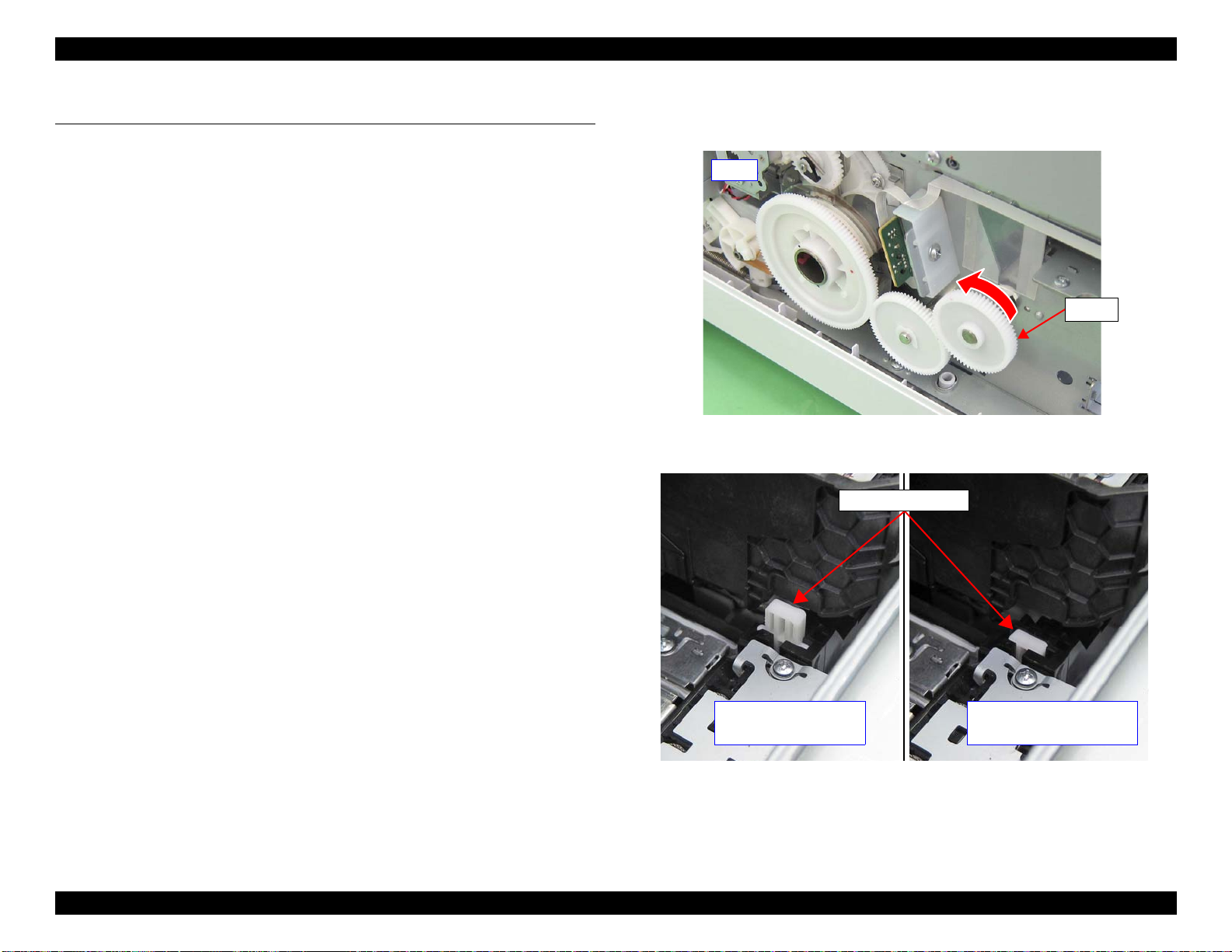
EPSON WF-R8590/WF-R8591/WF-R8593 Revision F
Left
Gear
CR locked
(The lever is raised)
CR Lock Lever
CR unlocked
(The Lever is lowered)
2.3 Disassembly and Assembly Procedure
2.3.1 Preparation for servicing
The common work used by the repair is described as follows.
Please refer to disassembly and reassembly sequence of the each parts whether
these work are necessary or not.
2.3.1.1 Unlocking the CR Unit
1. Remove the Panel Assy. (P.70)
2. Remove the Paper Support Support. (P.66)
3. Remove the Left ADF Hinge Cover. (P.67)
4. Remove the Right ADF Hinge Cover. (P.68)
5. Remove the ADF/ Scanner Unit. (P.216)
6. Remove the Panel Lower Front Cover. (P.73)
7. Remove the Right Upper Front Cover. (P.73)
8. Remove the Stacker Assy. (P.66)
9. Remove the Cassette Assy. (P.244)
16. Rotate the gear shown in the figure in the direction of the arrow to unlock the CR
Unit.
Figure 2-17. 4Unlocking the CR Unit
10. Remove the Front Cover Microswitch. (P.72)
11. Remove the Ink Supply BK Cover Assy. (P.195)
12. Remove the Ink Supply CL Cover Assy. (P.197)
13. Remove the Front Housing. (P.75)
14. Remove the Ferrite Core Holder. (P.74)
15. Remove the Middle Housing. (P.86)
Figure 2-18. Status of the CR Lock Lever
DISASSEMBLY/REASSEMBLY Disassembly and Assembly Procedure 61
Confidential
Page 62

EPSON WF-R8590/WF-R8591/WF-R8593 Revision F
CR Unit
Push and Fix the BK
Sensor lever by Tape
Push and Fix the BK
Sensor lever by Tape
When moving the CR Unit, make sure to hold it by the location
shown below.
Figure 2-19. Moving the CR Unit
2.3.1.2 Ink flushing
1. Replace the maintenance box with the one for the repair. (P.64)
Before performing Ink flushing, confirm the Maintenance Box
counter is 60% or less.
2. Open the Ink Supply BK Cover Assy.(P.195)
3. Push and fix the lever of the Ink Supply BK Cover Open Sensor with tape.
Figure 2-20. Fixing the Ink Supply BK Cover Open Sensor
4. Open the Ink Supply CL Cover Assy.(P.197)
5. Push and fix the lever of the Ink Supply CL Cover Open Sensor with tape.
Figure 2-21. Fixing the Ink Supply CL Cover Open Sensor
DISASSEMBLY/REASSEMBLY Disassembly and Assembly Procedure 62
Confidential
Page 63

EPSON WF-R8590/WF-R8591/WF-R8593 Revision F
AC Cable
Power Supply Unit
AC Inlet
6. Turn on the printer and conform the printer becomes ready, then remove the all Ink
Packs.
7. Perform the “Ink Flushing” with Adjustment Program.
Figure 2-22. Perform the ink flushing
Use the latest adjustment program (since Ver.1.06).
2.3.1.3 Initial Ink charge
1. Replace maintenance box with the one for the repair. (P.64)
2. Open the Ink Supply BK Cover Assy. (P.195)
3. Install the BK Ink Pack for the repair.
4. Open the Ink supply CL Cover Assy.(P.197)
5. Install the Y/M/C Ink Packs for the repair.
6. Close the Ink supply BK Cover Assy and the Ink supply CL cover Assy.
7. Plug the AC cable into the AC inlet of the printer.
8. Wait until the printer becomes ready.
9. Perform the “Initial ink charge” with the adjustment program.
8. Unplug the AC Cable from the AC Inlet of the Power Supply Unit.
Figure 2-24. Perform the Initial Ink charge
10. Perform the “Nozzle check print “with the adjustment program.
Figure 2-23. Unplug the AC Cable
11. If the nozzle-missing appeared in paper, perform the cleaning.
DISASSEMBLY/REASSEMBLY Disassembly and Assembly Procedure 63
Confidential
Page 64

EPSON WF-R8590/WF-R8591/WF-R8593 Revision F
Film
2.3.2 Consumables/Accessories
2.3.2.1 Maintenance Box
Take care not to drop the screws or the like on the Maintenance
Box. Doing so may damage the film on the Maintenance Box.
1. Open the Rear Cover Assy. (P.174)
2. Remove the Maintenance Box.
DISASSEMBLY/REASSEMBLY Disassembly and Assembly Procedure 64
Confidential
Page 65

EPSON WF-R8590/WF-R8591/WF-R8593 Revision F
Both
Hook (Left)
Hook (Right)
2.3.3 Housing
2.3.3.1 Front Cover Assy
For the screw types, see 2.1.1.1 Screw types used in the printer (p41).
1. Open the Front Cover Assy.
2. Disengage the both of the Front Cover Assy.
3. Disengage the left side hook using the flatbed screw driver.
4. Disengage the right side hook, and remove the Front Cover Assy.
Figure 2-26. Removing the Front Cover Assy (2)
The picture of Figure 2-25 and Figure 2-26 is WF-8590 series's
picture.
Figure 2-25. Removing the Front Cover Assy (1)
DISASSEMBLY/REASSEMBLY Disassembly and Assembly Procedure 65
Confidential
Page 66

EPSON WF-R8590/WF-R8591/WF-R8593 Revision F
Tab
Tab
2.3.3.2 Paper Support Support
For the screw types, see 2.1.1.1 Screw types used in the printer (p41).
1. Disengage the two tabs of the Paper Support Support, and remove the Paper
Support Support.
2.3.3.3 Stacker Assy
For the screw types, see 2.1.1.1 Screw types used in the printer (p41).
1. Remove the Stacker Assy.
Figure 2-27. Removing the Paper Support Support
DISASSEMBLY/REASSEMBLY Disassembly and Assembly Procedure 66
Confidential
Page 67

EPSON WF-R8590/WF-R8591/WF-R8593 Revision F
Tab
Tab
S5
ADF/ Scanner Unit
S5
2.3.3.4 Rear ASF Document Support Cover
For the screw types, see 2.1.1.1 Screw types used in the printer (p41).
1. Disengage the two tabs of the Rear ASF Document Support Cover, and remove the
Rear ASF Document Support Cover.
2.3.3.5 Left ADF Hinge Cover
For the screw types, see 2.1.1.1 Screw types used in the printer (p41).
1. Remove the Paper Support Support. (P.66)
2. Open the ADF/ Scanner Unit.
3. Remove the two screws (S5).
Figure 2-28. Removing the Rear ASF Document Support Cover
Figure 2-29. Removing the Left ADF Hinge Cover (1)
DISASSEMBLY/REASSEMBLY Disassembly and Assembly Procedure 67
Confidential
Page 68

EPSON WF-R8590/WF-R8591/WF-R8593 Revision F
ADF/ Scanner Unit
S5
ADF/ Scanner
Unit
S5
4. Remove the Left ADF Hinge Cover in the direction of the arrow while lifting the
ADF/ Scanner Unit.
Figure 2-30. Removing the Left ADF Hinge Cover (2)
2.3.3.6 Right ADF Hinge Cover
For the screw types, see 2.1.1.1 Screw types used in the printer (p41).
1. Remove the Paper Support Support. (P.66)
2. Open the ADF/ Scanner Unit.
3. Remove the three screws (S5).
Figure 2-31. Removing the Right ADF Hinge Cover (1)
DISASSEMBLY/REASSEMBLY Disassembly and Assembly Procedure 68
Confidential
Page 69

EPSON WF-R8590/WF-R8591/WF-R8593 Revision F
ADF/ Scanner Unit
4. Remove the Right ADF Hinge Cover in the direction of the arrow while lifting the
ADF/ Scanner Unit.
Figure 2-32. Removing the Right ADF Hinge Cover (2)
2.3.3.7 Paper Support
For the screw types, see 2.1.1.1 Screw types used in the printer (p41).
1. Remove the Paper Support Support. (P.66)
2. Remove the Left ADF Hinge Cover. (P.67)
3. Remove the Paper Support.
DISASSEMBLY/REASSEMBLY Disassembly and Assembly Procedure 69
Confidential
Page 70

EPSON WF-R8590/WF-R8591/WF-R8593 Revision F
Hook
S5
TabInsert positionTab Insert position
Screw Cover
2.3.3.8 Panel Assy
For the screw types, see 2.1.1.1 Screw types used in the printer (p41).
1. Open the ADF/ Scanner Unit.
2. Remove the four Screw Cover.
3. Remove the four screws (S5).
4. Insert a flathead screwdriver or a similar tool insert into the two insert potions
shown in Figure 2-33 and release each four tabs.
5. Disengage the five hooks, and remove the Panel Assy.
Figure 2-33. Removing the Panel Assy (1)
DISASSEMBLY/REASSEMBLY Disassembly and Assembly Procedure 70
Confidential
Page 71

EPSON WF-R8590/WF-R8591/WF-R8593 Revision F
Grounding wire
Panel Board
Speaker Cable
Panel FFC
Speaker Holder
Speaker Holder
Urethane
6. Disconnect the Panel FFC, grounding wire and Speaker Cable from the Panel
Board, and remove the Panel Assy.
Figure 2-34. Removing the Panel Assy (2)
Carry out the adjustments referring to "3.1 Required Adjustments"
(p279)
when the Panel Assy is replaced.
2.3.3.9 Speaker
For the screw types, see 2.1.1.1 Screw types used in the printer (p41).
1. Remove the Panel Assy. (P.70)
2. Remove the Speaker Holder Urethane outward.
3. Slide the Speaker Holder in the direction of the arrow, and remove the Speaker.
DISASSEMBLY/REASSEMBLY Disassembly and Assembly Procedure 71
Figure 2-35. Removing the Speaker
Confidential
Page 72

EPSON WF-R8590/WF-R8591/WF-R8593 Revision F
Hook
Hook
Connector
Cable
2.3.3.10 Front Cover Microswitch
For the screw types, see 2.1.1.1 Screw types used in the printer (p41).
1. Remove the Panel Assy. (P.70)
2. Remove the Paper Support Support. (P.66)
3. Remove the Left ADF Hinge Cover. (P.67)
4. Remove the Right ADF Hinge Cover. (P.68)
5. Remove the ADF/ Scanner Unit. (P.216)
6. Remove the Panel Lower Front Cover. (P.73)
9. Disconnect the cable from the connector.
10. Disengage the two hooks, and remove the Front Cover Microswitch.
Figure 2-36. Removing the Front Cover Microswitch
7. Open the Front Cover Assy. (P.65)
8. Remove the Right Upper Front Cover upward. (P.73)
DISASSEMBLY/REASSEMBLY Disassembly and Assembly Procedure 72
Confidential
Page 73

EPSON WF-R8590/WF-R8591/WF-R8593 Revision F
Ferrite Core
Grounding wire
S5
2.3.3.11 Right Upper Front Cover
For the screw types, see 2.1.1.1 Screw types used in the printer (p41).
1. Remove the Panel Assy. (P.70)
2. Remove the Paper Support Support. (P.66)
3. Remove the Left ADF Hinge Cover. (P.67)
4. Remove the Right ADF Hinge Cover. (P.68)
2.3.3.12 Panel Lower Front Cover
For the screw types, see 2.1.1.1 Screw types used in the printer (p41).
1. Remove the Panel Assy. (P.70)
2. Remove the Paper Support Support. (P.66)
3. Remove the Left ADF Hinge Cover. (P.67)
4. Remove the Right ADF Hinge Cover. (P.68)
5. Remove the ADF/ Scanner Unit. (P.216)
6. Release the grounding wire from hooks to prevent cutting.
7. Remove the Ferrite Core.
8. Remove the four screws (S5), and remove the Panel Lower Front Cover.
5. Remove the ADF/ Scanner Unit. (P.216)
6. Remove the Panel Lower Front Cover. (P.73)
7. Open the Front Cover Assy. (P.65)
8. Remove the Right Upper Front Cover upward.
Figure 2-37. Removing the Panel Lower Front Cover
DISASSEMBLY/REASSEMBLY Disassembly and Assembly Procedure 73
Confidential
Page 74

EPSON WF-R8590/WF-R8591/WF-R8593 Revision F
Connector
Ferrite Core
Ferrite Core
Ferrite Core
S5
Ferrite Core Holder
Grounding
Plate
Grounding
Plate
2.3.3.13 Panel FFC
For the screw types, see 2.1.1.1 Screw types used in the printer (p41).
1. Remove the Panel Assy. (P.70)
2. Remove the Paper Support Support. (P.66)
3. Remove the Left ADF Hinge Cover. (P.67)
4. Remove the Right ADF Hinge Cover. (P.68)
5. Remove the ADF/ Scanner Unit. (P.216)
6. Disconnect the Panel FFC from the connector of the Main Board.
7. Remove the two screws (S5), and remove the two Grounding Plate.
8. Remove the Ferrite Core Holder.
9. Remove the three Ferrite Core from the Middle Housing.
10. Remove the three Ferrite Core from the Panel FFC.
Figure 2-38. Removing the Panel FFC
DISASSEMBLY/REASSEMBLY Disassembly and Assembly Procedure 74
Confidential
Page 75

EPSON WF-R8590/WF-R8591/WF-R8593 Revision F
Press down with your finger.
Hook
Inner
Cover
S5
Hook
2.3.3.14 Front Housing
For the screw types, see 2.1.1.1 Screw types used in the printer (p41).
1. Remove the Panel Assy. (P.70)
2. Remove the Paper Support Support. (P.66)
3. Remove the Left ADF Hinge Cover. (P.67)
13. Remove the two screws (S5) that secure the Inner Cover of the Ink Supply BK
Assy.
14. Disengage the two hooks of the Inner Cover.
4. Remove the Right ADF Hinge Cover. (P.68)
5. Remove the ADF/ Scanner Unit. (P.216)
6. Remove the Panel Lower Front Cover. (P.73)
7. Remove the Right Upper Front Cover. (P.73)
8. Remove the Stacker Assy. (P.66)
9. Remove the Cassette Assy. (P.244)
10. Remove the Front Cover Microswitch. (P.72)
11. Remove the Ink Supply BK Cover Assy. (P.195)
12. Remove the Ink Supply CL Cover Assy. (P.197)
Figure 2-39. Removing the Ink Supply BK Assy (1)
DISASSEMBLY/REASSEMBLY Disassembly and Assembly Procedure 75
Confidential
Page 76

EPSON WF-R8590/WF-R8591/WF-R8593 Revision F
Inner Cover
Hook
Hook
Cable
Hook
Marking
Tube
15. Pull the Inner Cover toward you, and remove it upward.
Figure 2-40. Removing the Ink Supply BK Assy (2)
Make sure you insert two hook of the inner cover in the base of the
Ink Supply BK Assy. The Ink supply BK cover Assy does not open
if the hooks are not well
16. Release the cable of the Ink Supply BK Cover Open Sensor from the hook.
Figure 2-41. Removing the Ink Supply BK Assy (3)
17. Mark the tube at the point shown below.
Figure 2-42. Removing the Ink Supply BK Assy (4)
DISASSEMBLY/REASSEMBLY Disassembly and Assembly Procedure 76
Confidential
Page 77

EPSON WF-R8590/WF-R8591/WF-R8593 Revision F
S31
Hook
Hook
Hook
Hook
18. Remove the six screws (S31).
Figure 2-43. Removing the Ink Supply BK Assy (5)
19. Pull the Ink Supply BK Assy toward you to disengage the two hooks.
20. Lift the Ink Supply BK Assy to disengage the two hooks.
Figure 2-44. Removing the Ink Supply BK Assy (6)
Figure 2-45. Removing the Ink Supply BK Assy (7)
DISASSEMBLY/REASSEMBLY Disassembly and Assembly Procedure 77
Confidential
Page 78

EPSON WF-R8590/WF-R8591/WF-R8593 Revision F
Press down with your finger.
S5
Inner
Cover
Hook
Hook
21. Slide the Ink Supply BK Assy backward.
Figure 2-46. Sliding the Ink Supply BK Assy
22. Remove the three screws (S5) that secure the Inner Cover of the Ink Supply CL
Assy.
23. Disengage the two hooks of the Inner Cover.
Figure 2-47. Removing the Ink Supply CL Assy (1)
DISASSEMBLY/REASSEMBLY Disassembly and Assembly Procedure 78
Confidential
Page 79

EPSON WF-R8590/WF-R8591/WF-R8593 Revision F
Hook
Hook
Inner Cover
S5
Hook
Switch Cover
24. Pull the Inner Cover toward you, and remove it upward.
Make sure you insert two hook of the inner cover in the base of the
Ink Supply CL Assy. The Ink supply CL cover Assy does not open
if the hooks are not well.
Figure 2-48. Removing the Ink Supply CL Assy (2)
25. Remove the screw (S5).
26. Disengage the hook, and remove the Switch Cover.
Figure 2-49. Releasing the cable (1)
DISASSEMBLY/REASSEMBLY Disassembly and Assembly Procedure 79
Confidential
Page 80

EPSON WF-R8590/WF-R8591/WF-R8593 Revision F
Cable
Connector
Cable
Ferrite Core
Grounding
wire
S31
CN1
CSIC
Board (CL)
Hole
FFC
Grounding
wire
Tube (Y/M)
Tube (C)
Marking
Marking
Marking
27. Disconnect the cable from the connector.
Figure 2-50. Releasing the cable (2)
28. Release the cable of the Ink Supply CL Cover Open Sensor.
29. Remove the screw (S31), and remove the grounding wire.
Pull out the grounding wire from the hole shown in the figure
below.
30. Disconnect the FFC from the connector (CN1) of the CSIC Board (CL).
Figure 2-52. Removing the Ink Supply CL Assy (3)
31. Mark the tube at the point shown below.
DISASSEMBLY/REASSEMBLY Disassembly and Assembly Procedure 80
Figure 2-51. Releasing the cable (2)
Confirmed that the Ferrite Core is not on the CSIC Board (CL)
before turning on the power. Not only the CSIC Board (CL) but
also the main board is damaged if the Ferrite Core is on the CSIC
Board (CL).
Figure 2-53. Removing the Ink Supply CL Assy (4)
Confidential
Page 81

EPSON WF-R8590/WF-R8591/WF-R8593 Revision F
S31
S17
S15
S38
Hook
Hook
32. Remove the seven screws (S15:2 pcs, S31: 4pcs,S17: 1pice)
Figure 2-54. Removing the Ink Supply CL Assy (5)
33. Loose the screws(x4) and don’t remove it
34. Pull the Ink Supply CL Assy toward you to disengage the two hooks.
Figure 2-56. Removing the Ink Supply CL Assy (7)
Figure 2-55. Removing the Ink Supply CL Assy (6)
DISASSEMBLY/REASSEMBLY Disassembly and Assembly Procedure 81
Confidential
Page 82

EPSON WF-R8590/WF-R8591/WF-R8593 Revision F
Hook
35. Lift the Ink Supply CL Assy to disengage the four hooks.
36. Slide the Ink Supply CL Assy backward.
Figure 2-58. Sliding the Ink Supply CL Assy
Figure 2-57. Removing the Ink Supply CL Assy (7)
DISASSEMBLY/REASSEMBLY Disassembly and Assembly Procedure 82
Confidential
Page 83

EPSON WF-R8590/WF-R8591/WF-R8593 Revision F
S7
S17
Front Cover
Assy
S5
Tab (left upper)
Tab (right upper)
37. Open the Front Cover Assy.
38. Remove the nine screws (S5:1piece S7:6pcs: S17:2pcs)
Figure 2-59. Removing the Front Housing (1)
39. Release the two tabs on the upper part in the order from the left to the right. Use a
flat-head screwdriver to release the tab on the right because it is stiff.
Figure 2-60. Removing the Front Housing (2)
DISASSEMBLY/REASSEMBLY Disassembly and Assembly Procedure 83
Confidential
Page 84

EPSON WF-R8590/WF-R8591/WF-R8593 Revision F
Front Housing
Space
Lower Housing
Hole
Hook
Lower Housing
Hook
Front Housing
Space
Hole
40. On the lower left, insert the flat-head screwdriver (φ 3.5 mm or less) into the hole
on the Lower Housing in the direction of the arrow and release the hook.
41. By holding the point shown below, pull the Front Housing toward you to make
some space between the Front Housing and the Lower Housing.
Figure 2-61. Removing the Front Housing (3)
42. Insert the flat-head screwdriver into the space between the Front Housing and the
Lower Housing, and pull the Front Housing slightly toward you.
43. On the lower right, insert the flat-head screwdriver (φ 3.5 mm or less) into the hole
on the Lower Housing in the direction of the arrow and release the hook.
44. By holding the point shown below, pull the Front Housing toward you to make
some space between the Front Housing and the Lower Housing.
Figure 2-63. Removing the Front Housing (5)
45. Insert the flat-head screwdriver into the space between the Front Housing and the
Lower Housing, and pull the Front Housing slightly toward you.
Figure 2-64. Removing the Front Housing (6)
Figure 2-62. Removing the Front Housing (4)
DISASSEMBLY/REASSEMBLY Disassembly and Assembly Procedure 84
Confidential
Page 85

EPSON WF-R8590/WF-R8591/WF-R8593 Revision F
Lower Housing
Front Housing
Hook
Hook
Left Right
Lower Housing
Guide
Guide
Rib and hole
Lower Housing
Right
46. Insert the flat-head screwdriver between the Front Housing and the Lower
Housing, and pull the Front Housing toward you to remove it.
Figure 2-65. Removing the Front Housing (7)
47. Remove the Front Housing while pulling it toward you.
When installing the Front Housing, be careful of the following.
Insert the two hooks on the lower part straight into the holes on
the Lower Housing.
Make sure to align the guides on the Front Housing and the
Lower Housing correctly.
Insert the rib on the Front Housing into the hole on the Lower
Housing.
Figure 2-66. Removing the Front Housing (8)
DISASSEMBLY/REASSEMBLY Disassembly and Assembly Procedure 85
Confidential
Page 86

EPSON WF-R8590/WF-R8591/WF-R8593 Revision F
S15
Ink Holder
Cover
Clamp
Inside of the Ink
Supply Unit
Clamp
2.3.3.15 Middle Housing
For the screw types, see 2.1.1.1 Screw types used in the printer (p41).
1. Remove the Panel Assy. (P.70)
2. Remove the Paper Support Support. (P.66)
13. Remove the Front Housing. (P.75)
14. Remove the Ferrite Core Holder. (P.74)
15. Remove the two screws (S15), and remove the Ink Holder Cover.
Figure 2-67. Removing the Ink Holder Cover
16. Release the FFC from the three clamps.
3. Remove the Left ADF Hinge Cover. (P.67)
4. Remove the Right ADF Hinge Cover. (P.68)
5. Remove the ADF/ Scanner Unit. (P.216)
6. Remove the Panel Lower Front Cover. (P.73)
7. Remove the Right Upper Front Cover. (P.73)
8. Remove the Stacker Assy. (P.66)
9. Remove the Cassette Assy. (P.244)
10. Remove the Front Cover Microswitch. (P.72)
11. Remove the Ink Supply BK Cover Assy. (P.195)
12. Remove the Ink Supply CL Cover Assy. (P.197)
Figure 2-68. Releasing the Tube (BK) and FFC (1)
DISASSEMBLY/REASSEMBLY Disassembly and Assembly Procedure 86
Confidential
Page 87

EPSON WF-R8590/WF-R8591/WF-R8593 Revision F
Tube (BK)
Clamp
FFC
Ink Supply
BK Assy
Tube (BK)
Clamp
FFC
OK
No Good
OK
No Good
17. Release the Tube (BK) and FFC from the clamp.
To prevent the Tube (BK) from being folded, check the state
of the Tube (BK) shown in the figure below after installing
the Ink Supply BK Assy
Figure 2-69. Releasing the Tube (BK) and FFC (2)
In the following step, take care not to let the Tube (BK) or FFC get
caught on the clamp.
18. Move the Ink Supply BK Assy in front of the Middle Housing.
Figure 2-70. Moving the Ink Supply BK Assy
DISASSEMBLY/REASSEMBLY Disassembly and Assembly Procedure 87
Confidential
Page 88

EPSON WF-R8590/WF-R8591/WF-R8593 Revision F
Rear Cover Assy
S5
S17
S5
Tab and hole
Lower Housing
Tab and hole
Main Board
Grounding wire
Panel FFC
19. Open the Rear Cover Assy. (P.174)
20. Remove the six screws (S5: 4 pcs, S17: 2 pcs).
21. Release the two tabs of the Middle Housing from the holes of the Lower Housing.
Figure 2-72. Removing the Middle Housing (2)
22. Disconnect the Panel FFC from the connector of the Main Board.
23. Release the grounding wire.
DISASSEMBLY/REASSEMBLY Disassembly and Assembly Procedure 88
Figure 2-71. Removing the Middle Housing (1)
Figure 2-73. Removing the Middle Housing (3)
Confidential
Page 89

EPSON WF-R8590/WF-R8591/WF-R8593 Revision F
USB/FAX Cover
EXT Connector Cover
Flat-head screwdriver
Cable of the Front Cover
Microswitch
USB Cable
Grounding plate
24. While releasing the Middle Housing from the USB/FAX Cover, remove the
Middle Housing upward.
Figure 2-74. Removing the Middle Housing (4)
Remove the EXT Connector Cover if it is installed.
If it is difficult to release the cover, insert the flat-head
screwdriver to release fixing points on the Middle Housing.
Take care not to catch the USB Cable and the cable of the
Front Cover Microswitch.
Take care not to deform the grounding plate.
Install the Middle Housing taking care not to let it interfere
with the Front Frame and Rear ASF Unit.
DISASSEMBLY/REASSEMBLY Disassembly and Assembly Procedure 89
Confidential
Page 90
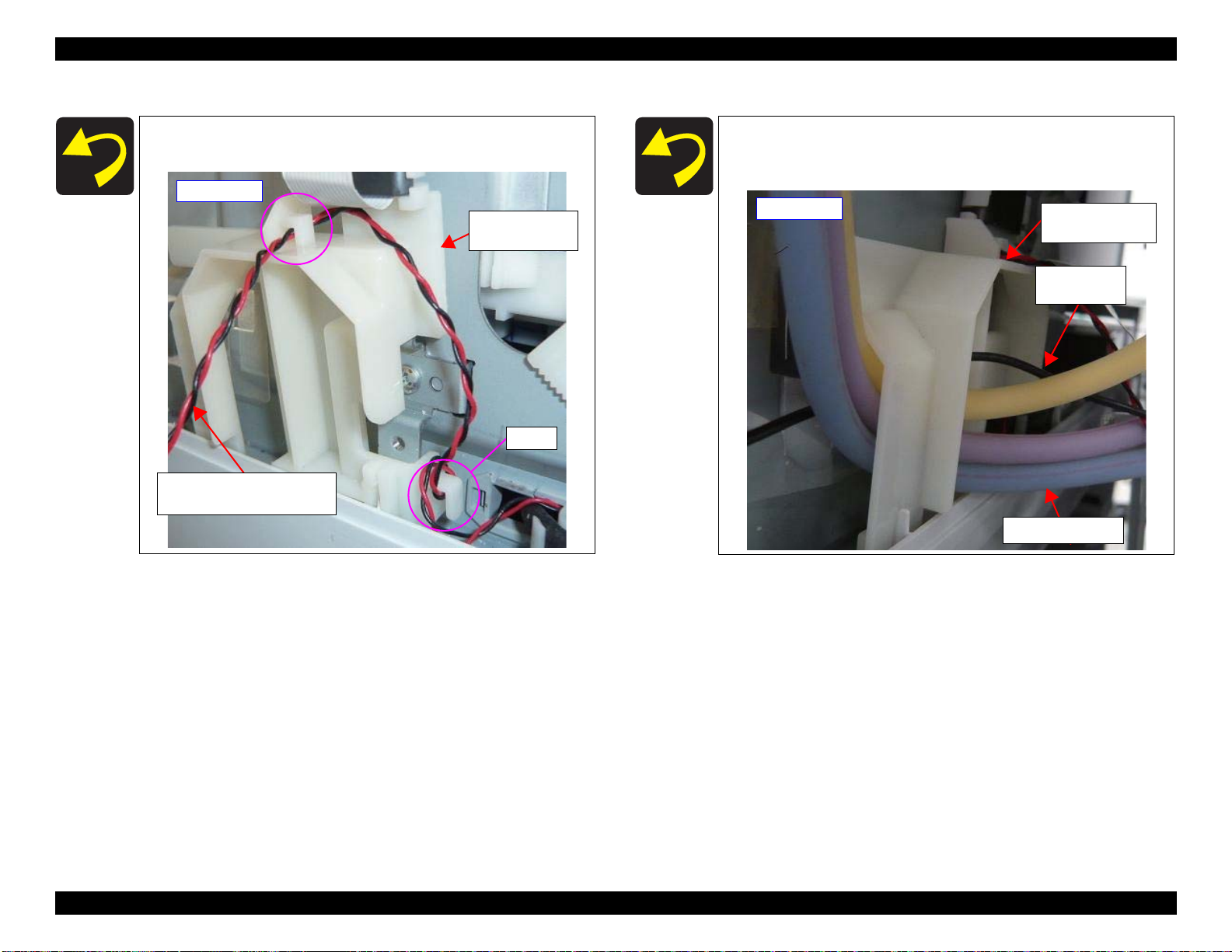
EPSON WF-R8590/WF-R8591/WF-R8593 Revision F
Right side
Cable of the Ink Supply
Cover Open Sensor
Right Lower
Tube Guide
Hook
Right Lower
Tube Guide
Tube (Y/M/C)
Grounding
wire
Right side
Route the cable of Ink Supply Cover Open Sensor through the
two hooks on the Right Lower Tube Guide.
Route the Tube (Y/M/C) and the grounding wire inside the
Right Lower Tube Guide, and insert them in the lower section
of the Right Lower Tube Guide.
DISASSEMBLY/REASSEMBLY Disassembly and Assembly Procedure 90
Confidential
Page 91

EPSON WF-R8590/WF-R8591/WF-R8593 Revision F
Right Upper Tube Guide
Left Tube Clip
Ink Supply Unit
Route the Tube (Y/M/C) as shown below.
DISASSEMBLY/REASSEMBLY Disassembly and Assembly Procedure 91
Confidential
Page 92

EPSON WF-R8590/WF-R8591/WF-R8593 Revision F
Hooks
Connector
Cable
2.3.4 Cover Sensors
2.3.4.1 Rear Cover Microswitch
For the screw types, see 2.1.1.1 Screw types used in the printer (p41).
1. Remove the Panel Assy. (P.70)
2. Remove the Paper Support Support. (P.66)
3. Remove the Left ADF Hinge Cover. (P.67)
4. Remove the Right ADF Hinge Cover. (P.68)
5. Remove the ADF/ Scanner Unit. (P.216)
16. Remove the USB/FAX Cover. (P.97)
17. Slide the Main Board Unit. (P.99)
18. Disengage the two hooks, and remove the Rear Cover Microswitch.
19. Disconnect the cable from the connector.
Figure 2-75. Removing the Rear Cover Microswitch
6. Remove the Panel Lower Front Cover. (P.73)
7. Remove the Right Upper Front Cover. (P.73)
8. Remove the Stacker Assy. (P.66)
9. Remove the Cassette Assy. (P.244)
10. Remove the Front Cover Microswitch. (P.72)
11. Remove the Ink Supply BK Cover Assy. (P.195)
12. Remove the Ink Supply CL Cover Assy. (P.197)
13. Remove the Front Housing. (P.75)
14. Remove the Ferrite Core Holder.(P.74)
15. Remove the Middle Housing. (P.86)
DISASSEMBLY/REASSEMBLY Disassembly and Assembly Procedure 92
Confidential
Page 93

EPSON WF-R8590/WF-R8591/WF-R8593 Revision F
Lower Paper Guide
S5
Hooks
Connector
Cable
2.3.4.2 Rear Cover PF Sensor
For the screw types, see 2.1.1.1 Screw types used in the printer (p41).
1. Remove the Duplex Unit. (P.175)
When removing the screws in the next step, use a 40 mm-long or
shorter stubby screwdriver.
3. Disengage the four hooks, and remove the Rear Cover PE Sensor.
4. Disconnect the cable from the connector.
Figure 2-77. Removing the Rear Cover PE Sensor
2. Remove the three screws (S5), and open the Lower Paper Guide.
Figure 2-76. Opening the Lower Paper Guide
DISASSEMBLY/REASSEMBLY Disassembly and Assembly Procedure 93
Confidential
Page 94

EPSON WF-R8590/WF-R8591/WF-R8593 Revision F
S5
Lower Paper Guide
Hooks
Connector
Cable
2.3.4.3 Right Pick Up Roller Sensor
For the screw types, see 2.1.1.1 Screw types used in the printer (p41).
1. Remove the Duplex Unit. (P.175)
2. Remove the four screws (S5), and remove the Lower Paper Guide.
3. Disengage the four hooks, and remove the Right Pick Up Roller Sensor.
4. Disconnect the cable from the connector.
Figure 2-79. Removing the Right Pick Up Roller Sensor
Figure 2-78. Opening the Lower Paper Guide
DISASSEMBLY/REASSEMBLY Disassembly and Assembly Procedure 94
Confidential
Page 95

EPSON WF-R8590/WF-R8591/WF-R8593 Revision F
Hooks
Connector
Cable
Hook
Connector
Cable
Hook
Bottom
2.3.4.4 Left Pick Up Roller Sensor
For the screw types, see 2.1.1.1 Screw types used in the printer (p41).
1. Remove the Duplex Unit. (P.175)
2. Open the Lower Paper Guide. (refer to (p94))
3. Disengage the four hooks, and remove the Left Pick Up Roller Sensor.
4. Disconnect the cable from the connector.
2.3.4.5 Casette Microswitch
For the screw types, see 2.1.1.1 Screw types used in the printer (p41).
1. Remove the Cassette Assy. (P.244)
2. Disengage the two hooks, and remove the Casette Microswitch.
3. Disconnect the cable from the connector.
Figure 2-81. Removing the Casette Microswitch
Figure 2-80. Removing the Left Pick Up Roller Sensor
DISASSEMBLY/REASSEMBLY Disassembly and Assembly Procedure 95
Confidential
Page 96

EPSON WF-R8590/WF-R8591/WF-R8593 Revision F
Hooks
Bottom
Connector
Cable
2.3.4.6 PE Sensor
For the screw types, see 2.1.1.1 Screw types used in the printer (p41).
1. Remove the Cassette Assy. (P.244)
2. Disengage the four hooks, and remove the PE Sensor.
3. Disconnect the cable from the connector.
Figure 2-82. Removing the PE Sensor
DISASSEMBLY/REASSEMBLY Disassembly and Assembly Procedure 96
Confidential
Page 97

EPSON WF-R8590/WF-R8591/WF-R8593 Revision F
S1
2.3.5 Electric Circuit Components
2.3.5.1 USB/FAX Cover
For the screw types, see 2.1.1.1 Screw types used in the printer (p41).
1. Remove the Panel Assy. (P.70)
2. Remove the Paper Support Support. (P.66)
3. Remove the Left ADF Hinge Cover. (P.67)
4. Remove the Right ADF Hinge Cover. (P.68)
16. Remove the two screws (S1), and remove the USB/FAX Cover.
Figure 2-83. Removing the USB/FAX Cover
5. Remove the ADF/ Scanner Unit. (P.216)
6. Remove the Panel Lower Front Cover. (P.73)
7. Remove the Right Upper Front Cover. (P.73)
8. Remove the Stacker Assy. (P.66)
9. Remove the Cassette Assy. (P.244)
10. Remove the Front Cover Microswitch. (P.72)
11. Remove the Ink Supply BK Cover Assy. (P.195)
12. Remove the Ink Supply CL Cover Assy. (P.197)
13. Remove the Front Housing. (P.75)
14. Remove the Ferrite Core Holder.(P.74)
15. Remove the Middle Housing. (P.86)
DISASSEMBLY/REASSEMBLY Disassembly and Assembly Procedure 97
Confidential
Page 98

EPSON WF-R8590/WF-R8591/WF-R8593 Revision F
Main Board
USB Cable
S17
Connector
Clamp
Clamp
2.3.5.2 USB Connector Assy
For the screw types, see 2.1.1.1 Screw types used in the printer (p41).
1. Remove the Panel Assy. (P.70)
2. Remove the Paper Support Support. (P.66)
13. Remove the Front Housing. (P.75)
14. Remove the Ferrite Core Holder.(P.74)
15. Remove the Middle Housing. (P.86)
16. Disconnect the USB Cable from the connector of the Main Board.
17. Release the USB Cable from the two clamps.
18. Remove the screw (S17), and remove the USB Connector Assy.
3. Remove the Left ADF Hinge Cover. (P.67)
4. Remove the Right ADF Hinge Cover. (P.68)
5. Remove the ADF/ Scanner Unit. (P.216)
Figure 2-84. Removing the USB Connector Assy
6. Remove the Panel Lower Front Cover. (P.73)
7. Remove the Right Upper Front Cover. (P.73)
8. Remove the Stacker Assy. (P.66)
9. Remove the Cassette Assy. (P.244)
10. Remove the Front Cover Microswitch. (P.72)
11. Remove the Ink Supply BK Cover Assy. (P.195)
12. Remove the Ink Supply CL Cover Assy. (P.197)
DISASSEMBLY/REASSEMBLY Disassembly and Assembly Procedure 98
Confidential
Page 99

EPSON WF-R8590/WF-R8591/WF-R8593 Revision F
Hook
USB Cable
Route the USB Cable through the hook on the USB Connector
Assy.
2.3.5.3 Main Board Unit
For the screw types, see 2.1.1.1 Screw types used in the printer (p41).
1. Remove the Panel Assy. (P.70)
2. Remove the Paper Support Support. (P.66)
3. Remove the Left ADF Hinge Cover. (P.67)
4. Remove the Right ADF Hinge Cover. (P.68)
5. Remove the ADF/ Scanner Unit. (P.216)
6. Remove the Panel Lower Front Cover. (P.73)
7. Remove the Right Upper Front Cover. (P.73)
8. Remove the Stacker Assy. (P.66)
9. Remove the Cassette Assy. (P.244)
10. Remove the Front Cover Microswitch. (P.72)
11. Remove the Ink Supply BK Cover Assy. (P.195)
12. Remove the Ink Supply CL Cover Assy. (P.197)
13. Remove the Front Housing. (P.75)
DISASSEMBLY/REASSEMBLY Disassembly and Assembly Procedure 99
Confidential
Page 100

EPSON WF-R8590/WF-R8591/WF-R8593 Revision F
Tube (C)
Left Tube Clip
Tube (Y)
Tube (M)
Tube Clamp
14. Remove the Ferrite Core Holder.(P.74)
15. Remove the Middle Housing. (P.86)
16. Remove the USB/FAX Cover. (P.97)
17. Release the Ink Tube (Y,M,C) from the Left Tube Clip.
18. Release the Ink Tube (Y,M,C) from the Tube Clamp.
Figure 2-86. Release the Ink Tube (Y,M,C)
Figure 2-85. Release the Ink Tube (Y,M,C)
DISASSEMBLY/REASSEMBLY Disassembly and Assembly Procedure 100
Confidential
 Loading...