


25M01A-100 to 25M01A-199
HSI Single Stage Combination Gas Valve
INSTALLATION INSTRUCTIONS
Operator: Save these instructions for future use!
FAILURE TO READ AND FOLLOW ALL INSTRUCTIONS CAREFULLY BEFORE INSTALLING OR OPERATING THIS CONTROL COULD CAUSE PERSONAL INJURY AND/OR PROPERTY DAMAGE.
DESCRIPTION
The 25M01A series valve is a combination gas pressure regulator and dual automatic gas valve. These valves are designed for gas clothes dryers with Hot Surface Ignition (HSI) systems. These valves are equipped with redundant and main solenoid valves that control the gas flow to the burner, and a direct acting pressure regulator.
SPECIFICATIONS
Type of Gas: Natural gas
LP gas (use conversion kit)
Pressure Regulator Setting: Nat. Gas – 2.5" to 5.4" W.C. LP Gas – 7.0 to 12.0"W.C.
Ambient Temperature: 32° to 155°F
Pressure Rating: 14" W.C. (1/2 PSI) max.
Voltage: 120 VAC
Frequency: 60 Hz
Current: .06 amps
Mounting Positions:
Control may be mounted in the following positions: horizontal, vertical or 90° of horizontal. NOT UPSIDE DOWN.
Capacity (BTU/hr) at |
1” pressure drop across valve |
CONTENTS |
|
|
|
Description......................................................... |
1 |
|
|
Specifications .................................................... |
1 |
|
|
Precautions ....................................................... |
2 |
|
|
Installation ......................................................... |
2 |
|
|
Adjustment ........................................................ |
4 |
|
|
Pressure Regulator Adjustment |
|
|
|
Lighting Instructions ........................................... |
5 |
|
|
|
|
|
|
|
|
|
|
|
White-Rodgers is a division |
PART NO. 37-6643A |
|
|
of Emerson Electric Co. |
0530 |
|
www.white-rodgers.com
PRECAUTIONS
DO NOT BEGIN INSTALLATION UNTIL YOU READ THE FOLLOWING PRECAUTIONS.
! WARNING |
|
If you do not follow these instructions exactly, a fire or explosion |
|
may result causing property damage, personal injury or loss of life. |
|
|
|
|
1.Failure to turn off electric or main gas supply to clothes dryer could cause personal injury and/or property damage by shock, gas suffocation, fire, and/or explosion.
2.Do not use this control on circuits exceeding specified voltage. Higher voltage will damage the control and may cause shock or fire hazard.
3.NEVER USE FLAME OR ANY KIND OF SPARK TO CHECK FOR GAS LEAKS–COULD CAUSE FIRE AND/OR EXPLOSION.
4.Do not use a control set for natural gas with LP gas, or a control set for LP gas with natural gas. Personal injury and/or property damage, gas suffocation, fire, and/or explosion may result.
! CAUTION
1.Do not short out terminals on gas valve or primary control to test. Short or incorrect wiring can cause equipment damage, property damage, and/or personal injury.
2.This control is not intended for use in locations where it may come in direct contact with water. Suitable protection must be provided to shield the control from exposure to water (dripping, spraying, rain, etc.).
INSTALLATION
1.Before attempting to service dryer, unplug power cord, turn off main gas supply and consult dryer manufacturer's instructions for accessing gas valve.
2.Disconnect exhaust vent duct.
3.Disconnect gas line from rear of dryer.
4.Remove access panel from dryer. On some models this involves removing the entire front panel.
5.The gas valve/burner assembly should now be visible.
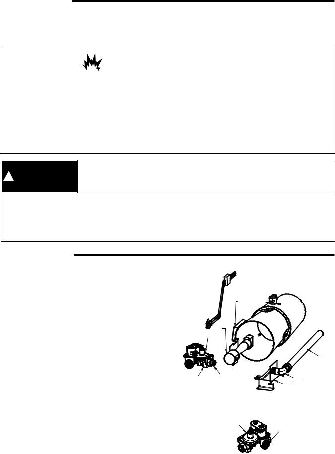
6.The burner assembly consists of (see figure 1 & 2):
a.Gas inlet pipe.
b.Brass inlet fitting with union – some models may also have a manual shut-off valve.
c.Gas valve.
d.Mounting bracket.
e.Burner orifice.
f.Burner assembly with air shutter.
g.Igniter.
h.Radiant sensor – located on heat exchanger on some models.
7.Disconnect the wiring harness from gas valve and igniter.
8.Remove screw(s) fastening the mounting bracket to the bottom of dryer.
9.Burner assembly should now be free to slide out of the front of dryer. Take care not to bump or jar igniter. It is very fragile.
10.Remove the gas inlet pipe by unscrewing the union.
11.Remove screw(s) fastening the gas valve to the mounting bracket and set them aside. They will be reused.
G
H
F
E (not shown)
A
C |
B |
B |
|
|
D |
|
|
Figure 1 |
|
|
C |
|
|
E |
Figure 2
2
 Loading...