


Use, Care, and Installation Guide Guide d’utilisation, d’entretien et d’installation
Guía de instalación, uso y mantenimiento
READ AND SAVE THESE INSTRUCTIONS LISEZ CES INSTRUCTIONS ET CONSERVEZ-LES LEA Y GUARDE ESTAS INSTRUCCIONES
English |
Contents |
page |
2 |
Français |
Sommaire |
page |
12 |
Español |
Contenido |
página |
22 |
English |
|
Contents |
|
Important safety notice........................................................................................................................................ |
3 |
Electrical & installation requirements ............................................................................................................... |
4 |
Electrical requirements ................................................................................................................................................................................. |
4 |
Before installing the hood ............................................................................................................................................................................. |
4 |
List of materials.................................................................................................................................................... |
5 |
Parts supplied ............................................................................................................................................................................................... |
5 |
Parts not supplied ......................................................................................................................................................................................... |
5 |
Location requirements......................................................................................................................................... |
5 |
Dimensions and clearances................................................................................................................................ |
5 |
Product dimensions............................................................................................................................................. |
6 |
Venting requirements........................................................................................................................................... |
6 |
Venting methods................................................................................................................................................... |
7 |
Install range hood into hood cabinet................................................................................................................. |
7 |
Prepare the location....................................................................................................................................................................................... |
7 |
Complete installation..................................................................................................................................................................................... |
8 |
To uninstall the single or dual blower motor.................................................................................................................................................. |
8 |
Install the range hood into the hood cabinet.................................................................................................................................................. |
8 |
To install the single or dual blower motor....................................................................................................................................................... |
8 |
Make electrical power supply insert............................................................................................................................................................... |
9 |
Complete installation and check operation....................................................................................................... |
9 |
Hood insert use.................................................................................................................................................... |
10 |
Control buttons............................................................................................................................................................................................... |
10 |
Maintenance......................................................................................................................................................... |
10 |
Cleaning......................................................................................................................................................................................................... |
10 |
Metal grease filter........................................................................................................................................................................................... |
10 |
Replacing the halogen lamps......................................................................................................................................................................... |
10 |
Warranty ............................................................................................................................................................... |
11 |
APPROVED FOR RESIDENTIAL APPLIANCES |
|
FOR RESIDENTIAL USE ONLY |
|
READ AND SAVE THESE INSTRUCTIONS |
|
PLEASE READ ENTIRE INSTRUCTIONS BEFORE PROCEEDING. INSTALLATION MUST COMPLY WITH ALL LOCAL CODES.
IMPORTANT: Save these Instructions for the Local Electrical Inspector’s use. INSTALLER: Please leave these Instructions with this unit for the owner. OWNER: Please retain these instructions for future reference.
Safety Warning: Turn off power circuit at service panel and lock out panel, before wiring this appliance. Requirement: 120 V AC, 60 Hz. 15 or 20 A Branch Circuit
READ AND SAVE THESE INSTRUCTIONS
Important Safety Notice
CAUTION
FOR GENERAL VENTILATING USE ONLY. DO NOT USE TO EXHAUST HAZARDOUS OR EXPLOSIVE MATERIALS OR VAPOURS.
WARNING
TO REDUCE THE RISK OF FIRE, ELECTRIC SHOCK, OR INJURY TO PERSONS, OBSERVE THE FOLLOWING:
A.Use this unit only in the manner intended by the manufacturer. If you have questions, contact the manufacturer.
B.Before servicing or cleaning the unit, switch power off at service panel and lock service panel disconnecting means to prevent power from being switched on accidentally. When the service disconnecting means cannot be locked, securely fasten a prominent warning device, such as a tag, to the service panel.
C.Installation Work and Electrical Wiring Must Be Done By
Qualified Person(s) In Accordance With All Applicable
Codes & Standards, Including Fire-rated Construction.
D.Sufficient air is needed for proper combustion and exhausting of gases through the flue (Chimney) of fuel burning equipment to prevent backdrafting.
Follow the heating equipment manufacturers guideline and safety standards such as those published by the
National Fire Protection Association (NFPA), the American Society for Heating,
Refrigeration and Air Conditioning Engineers (ASHRAE), and the local code authorities.
E.When cutting or drilling into wall or ceiling, do not damage electrical wiring and other hidden utilities.
F.Ducted systems must always be vented to the outdoors.
CAUTION
To reduce risk of fire and to properly exhaust air, be sure to duct air outside - do not vent exhaust air into spaces within walls, ceilings, attics, crawl spaces, or garages.
WARNING
TO REDUCE THE RISK OF FIRE, USE ONLY METAL DUCT WORK.
Install this hood in accordance with all requirements specified.
WARNING
To Reduce The Risk Of Fire Or Electric Shock, Do Not
Use This Hood With Any External Solid State Speed
Control Device.
WARNING
TO REDUCE THE RISK OF A RANGE TOP GREASE FIRE.
a)Never leave surface units unattended at high settings. Boilovers cause smoking and greasy spillovers that may ignite. Heat oils slowly on low or medium settings.
b)Always turn hood ON when cooking at high heat or when flambeing food (I.e. Crepes Suzette, Cherries Jubilee, Peppercorn Beef Flambe’).
c)Clean ventilating fans frequently. Grease should not be allowed to accumulate on fan or filter.
d)Use proper pan size. Always use cookware appropriate for the size of the surface element.
WARNING
TO REDUCE THE RISK OF INJURY TO PERSONS, IN THE EVENT OF A RANGE TOP GREASE FIRE,
OBSERVE THE FOLLOWING:a
a)SMOTHER FLAMES with a close-fitting lid, cookie sheet, or other metal tray, then turn off the gas burner or the electric element. BE CAREFUL TO PREVENT BURNS. If the flames do not go out immediately, EVACUATE AND CALL THE FIRE DEPARTMENT.
b)NEVER PICK UP A FLAMING PAN - you may be burned.
c)DO NOT USE WATER, including wet dishcloths or towels - a violent steam explosion will result.
d)Use an extinguisher ONLY if:
1)You know you have a class ABC extinguisher, and you already know how to operate it.
2)The fire is small and contained in the area where it started.
3)The fire department is being called.
4)You can fight the fire with your back to an exit.
aBased on “Kitchen Fire Safety Tips” published by NFPA.
OPERATION
a. Always leave safety grills and filters in place. Without these components, operating blowers could catch onto hair, fingers and loose clothing.
The manufacturer declines all responsibility in the event of failure to observe the instructions given here for installation, maintenance and suitable use of the product. The manufacturer further declines all responsibility for injury due to negligence and the warranty of the unit automatically expires due to improper maintenance.
Electrical & Installation requirements
Electrical requirements
IMPORTANT
Observe all governing codes and ordinances.
It is the customer’s responsibility:
To contact a qualified electrical installer.
To assure that the electrical installation is adequate and in conformance with National Electrical Code, ANSI/NFPA 70
— latest edition*, or CSA Standards C22.1-94, Canadian
Electrical Code, Part 1 and C22.2 No.0-M91 - latest edition** and all local codes and ordinances.
If codes permit and a separate ground wire is used, it is recommended that a qualified electrician determine that the ground path is adequate.
Do not ground to a gas pipe.
Check with a qualified electrician if you are not sure range hood is properly grounded.
Do not have a fuse in the neutral or ground circuit.
IMPORTANT
Save Installation Instructions for electrical inspector’s use.
The range hood must be connected with copper wire only.
The range hood should be connected directly to the fused disconnect (Or circuit breaker) box through metal electrical conduit.
Wire sizes must conform to the requirements of the National Electrical Code ANSI/NFPA 70 — latest edition*, or CSA
Standards C22.1-94, Canadian Electrical Code Part 1 and C22.2 No. 0-M91 - latest edition** and all local codes and ordinances.
A U.L.- or C.S.A.-listed conduit connector must be provided at each end of the power supply conduit (at the range hood and at the junction box).
Copies of the standards listed may be obtained from:
* National Fire Protection Association Batterymarch Park Quincy,
Massachusetts 02269
** CSA International 8501 East Pleasant Valley Road Cleveland, Ohio 44131-5575
Before installing the hood
1.For the most efficient air flow exhaust, use a straight run or as few elbows as possible.
CAUTION: Vent unit to outside of building, only.
2.At least two people are necessary for installation.
3.Fittings material is provided to secure the hood to most types of walls/ceilings, consult a Qualified Installer, check if they perfectly fit with your cabinet/wall.
4.Do not use flex ducting.
5.COLD WEATHER installations should have an additional backdraft damper installed to minimize backward cold air flow and a nonmetallic thermal break to minimize conduction of outside temperatures as part of the ductwork. The damper should be on the cold air side of the thermal break.
The break should be as close as possible to where the ducting enters the heated portion of the house.
6.Make-Up air: Local building codes may require the use of Make-Up Air Systems when using Ducted Ventilation Systems greater than specified CFM of air movement. The specified CFM varies from locale to locale. Consult your HVAC professional for specific requirements in your area.
NOTE:
Use the Range Hood model EAR628SS (Single Blower Motor=600CFM) only above a cooktop with a maximum of
65,000 Btus.
Use the Range Hood models EAR134SS, EAR140SS & EAR146SS (Dual Blower Motor=1200CFM) above cooktops rated higher than 65,000 Btus.
List of Materials
Parts supplied
CAUTION!
Remove carton carefully, wear gloves to protect against sharp edges.
WARNING!
Remove the protective film covering the product before putting into operation.
•Metal grease filters:
-Model EAR628SS: 2 filters
-Model EAR134SS: 2 filters
-Model EAR140SS: 3 filters
-Model EAR146SS: 4 filters
•1 - 10” (25.4 cm) square to 10” (25.4 cm) round duct transition with damper.
•2 - 1½” x 22” stainless steel hood spacer
•4 - 5 x 45 mm mounting screws for cabinet
•10 - 4.2 x 8 mm mounting screws
•2 - 18mm spacer screw (only on model EAR628SS)
Parts not supplied
Optional Accessories
•Home power supply cable
•1 - ½” (1.3 cm) UL listed or CSA approved strain relief
•3 - UL listed wire connectors
•1 wall or roof cap
•Metal vent system
Tools/Materials required
•Level
•Drill
•1¼” (3 cm) drill bit
•⅛” (3 mm) drill bit
•Pencil
•Wire stripper or knife
•Tape measure or ruler
•Pliers
•Caulking gun and weatherproof caulking compound
•Vent clamps
•Jigsaw or keyhole saw
•Flat-blade screwdriver
•Metal snips
•Phillips screwdriver
Location Requirements
IMPORTANT: Observe all governing codes and ordinances. Have a qualified technician install the hood insert. It is the installer’s responsibility to comply with installation clearances specified on the model/serial rating plate. The model/serial rating plate is located on the rear wall’s right side of the hood insert.
The hood insert location should be away from strong draft areas, such as windows, doors and strong heating vents. Cabinet opening dimensions that are shown must be used. Given dimensions provide minimum clearance.
The hood insert must be surrounded by a custom built enclosure with hood cabinet capable of supporting 75 lb (34 kg).
Grounded electrical outlet is required. See “Electrical
Requirements” section on page 4.
All openings in ceiling and wall where canopy hood will be installed must be sealed.
For Mobile Home Installations
The installation of this hood insert must conform to the Manufactured Home Construction Safety Standards, Title 24 CFR, Part 328 (formerly the Federal Standard for Mobile Home Construction and Safety, Title 24, HUD, Part 280) or when such standard is not applicable, the standard for Manufactured Home Installation 1982 (Manufactured Home Sites, Communities and Setups) ANSI A225.1/NFPA 501A, or latest edition, or with local codes.
Dimensions and Clearances
This range hood has the flexibility to be installed in two different ways, depending on the width measurement or working area between the left and right cabinetry. Before beginning, it is important to determine the dimension of this working area and to consider the measurements detailed in the table below.
Range |
Range Width |
Range Width |
Hood |
without spacers |
with spacers |
Models |
|
|
|
|
|
EAR628SS |
28½” (72 cm) |
30” (76.2 cm) |
|
|
|
EAR134SS |
34½” (87 cm) |
36” (91.44 cm) |
|
|
|
EAR140SS |
40½” (102 cm) |
42” (106.68 cm) |
|
|
|
EAR146SS |
46½” (117.5 cm) |
48” (121.92 cm) |
|
|
|
|
See the above table |
|
|
|
|
22” |
|
|
|
(55.9 cm) |
Hood insert cabinet must be |
|
|
Hood insert |
capable of supporting |
|
|
depth |
75 lb (34 kg) |
“X” bottom of canopy to |
||
|
cooking surface |
||
IMPORTANT:
Minimum distance “X”: 24” (61 cm) from electric cooking surfaces. Minimum distance “X”: 30” (76.2 cm) from gas cooking surfaces. Suggested maximum distance “X”: 36” (91.4 cm).
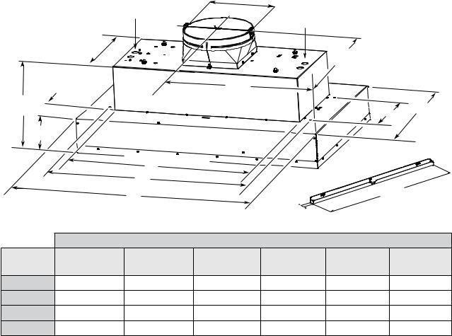
Product Dimensions
|
34½”, 40½” & 46½” |
97/8” (25.11 cm) |
|
|
|
|
|
|
|
|
|
|
|
||
|
models wiring knockout |
|
28½” model |
|
|
|
|
|
|
|
|
wiring knockout |
|
|
|
|
123/8” |
|
|
|
|
|
|
|
(31.4 cm) |
|
|
|
11” |
|
|
|
|
|
|
|
|
|
|
|
|
|
|
|
(28 cm) |
|
|
|
413/16” |
|
E |
|
|
|
|
(12.2 cm) |
|
|
|
|
|
||
11½” |
|
|
|
|
|
|
|
(29.2 cm) |
|
|
|
|
|
D |
22” (55.9cm) |
|
|
|
|
|
|
|
|
51/16” |
|
|
|
|
|
|
|
(12.8 cm) |
|
|
|
|
|
|
|
|
|
C |
|
|
|
|
|
|
|
B |
|
*HOOD SPACER |
|
|
|
|
|
|
|
22” (55.9cm) |
|||
|
|
A |
|
|
|||
|
|
|
|
|
|
|
|
|
|
|
|
¾” |
|
|
|
|
|
|
|
(1.9 cm) |
|
|
|
|
|
|
DIMENSIONS |
|
|
|
|
Range |
DIM A |
DIM A |
DIM B |
DIM C |
DIM D |
|
DIM E |
Hood mod. |
|
+ spacers |
|
mounting holes |
mounting holes |
|
|
EAR628SS |
28½” (72 cm) |
30” (76.2 cm) |
245/16” (61.8 cm) |
22” (56 cm) |
11” (28 cm) |
|
14” (36 cm) |
EAR134SS |
34½” (87 cm) |
36” (91.44 cm) |
2913/16” (75.76 cm) |
27½” (70 cm) |
101/16” (25.6 cm) |
|
17” (43.6 cm) |
EAR140SS |
40½” (102 cm) |
42” (106.68 cm) |
2913/16” (75.76 cm) |
27½” (70 cm) |
101/16” (25.6 cm) |
|
20” (51.2 cm) |
EAR146SS |
46½” (117.5 cm) |
48” (121.92 cm) |
2913/16” (75.76 cm) |
27½” (70 cm) |
101/16” (25.6 cm) |
|
23” (58.8 cm) |
Venting Requirements
Vent system must terminate to the outdoors.
•Do not terminate the vent system in an attic or enclosed areas.
•Do not use 4” (10.2 cm) laundry-type wall caps.
•Use metal vent only. Rigid metal vent is recommended. Plastic or metal foil vent is not recommended.
•The length of vent system and number of elbows should be kept to a minimum to provide efficient performance.
For the most efficient and quiet operation:
•Use no more than three 90° elbows.
•Make sure there is a minimum of 24” (61.0 cm) of straight vent between the elbows if more than 1 elbow is used.
•Do not install 2 elbows together.
Cold weather installations
An additional back draft damper should be installed to minimize backward cold air flow as part of the vent system.
A thermal break should be installed to minimize conduction of outside temperatures as part of the vent system.
The damper should be on the cold air side of the thermal break. The break should be as close as possible to where the vent system enters the heated portion of the house.
Make-Up air
Local building codes may require the use of make-up air systems when using ventilation systems greater than specified CFM of air movement. The specified CFM varies from locale
•Use clamps to seal all joints in the vent system and use to locale. Consult your HVAC professional for specific require-
furnace duct tape to fully seal joint connection. |
ments in your area. |
•Use caulking to seal exterior wall or roof opening around the cap.
•The size of the vent should be uniform.
Venting Methods
•The hood exhaust opening has a 10” diameter round vent outlet.
•On installations using the 600 CFM Blower Motor Systems, 8” round vent system is recommended.
•On installations using the 1200 CFM Blower Motor Systems, a 10” round vent system should be used.
•You can use a smaller round vent system , but there will be a louder sound level.
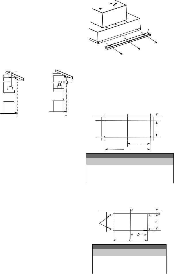
NOTE: Flexible vent is not recommended. Flexible vent creates back pressure and air turbulence that greatly reduce performance. Vent system can terminate either through the roof or wall. To vent through the wall, a 90° elbow is needed.
Roof venting |
|
Wall Venting |
B |
|
|
A |
A |
B |
A. 10” (25.4 cm) round vent |
A. 10” (25.4 cm) round vent |
B. Roof cap |
B.Wall cap |
Prepare the Location
1.Disconnect power.
2.Determine which venting method to use: roof or wall exhaust.
3.Select a flat surface for assembling the hood insert.
Place covering over that surface.
•It is recommended that the vent system be installed before hood is installed.
•Before making cutouts, make sure there is proper clearance within the ceiling or wall for exhaust vent.
•Hood insert should be installed a minimum 24” (61 cm) above an electric cooktop surface and 30” (76.2 cm) above a gas cook top surface. The maximum recommended height over both cook tops is 36” (91.44 cm).
•Check that all installation parts have been removed from the shipping carton.
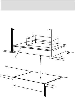
4.Using 2 or more people, lift hood insert onto covered surface.
5.Remove the filters. See the “Cleaning” section.
Stainless Steel Hood Spacer Installation
You can elongate 1.5” of your range hood width (¾” per side), installing the stainless steel spacers included with your range hood.
1.Unpack the spacer and take off the protective.
2.Put each one on the right and the left side
3.Fasten hood spacer using four 5 x 45 mm screws to the hood cabinet and tighten securely.
Hood spacer
Install Range Hood into Hood Cabinet
The range hood attaches to the hood cabinet using four mounting screws and washers.
NOTE: Hood cabinet must be capable of supporting 75 lb (34 kg).
Prepare Range hood for mounting into cabinet
1.Mark the locations for the four mounting screws on the hood cabinet as shown below.
2.Using a ⅛” (3 mm) drill bit, drill the 4 holes.
|
A |
|
B |
|
C |
F |
|
A. Centerline |
D |
|
E |
MOUNTING HOLE DIMENSIONS
Hood |
DIM B |
DIM C |
DIM D |
DIM E |
DIM F |
Insert |
|
|
|
|
|
|
|
|
|
|
|
EAR628SS |
5½” (14 cm) |
11” (28 cm) |
125⁄32” (30.9 cm) |
245⁄16” (61.8 cm) |
Ø1/8” (3mm) |
|
|
|
|
|
|
EAR134SS |
6” (15.5 cm) |
101⁄16” (25.6 cm) |
1415⁄16” (38 cm) |
2913⁄16” (75.8 cm) |
Ø1/8” (3mm) |
|
|
|
|
|
|
EAR140SS |
6” (15.5 cm) |
101⁄16” (25.6 cm) |
1415⁄16” (38 cm) |
2913⁄16” (75.8 cm) |
Ø1/8” (3mm) |
|
|
|
|
|
|
EAR146SS |
6” (15.5 cm) |
101⁄16” (25.6 cm) |
1415⁄16” (38 cm) |
2913⁄16” (75.8 cm) |
Ø1/8” (3mm) |
|
|
|
|
|
|
3.Mark the cutout for the rectangular clearance hole for the upper range hood motor housing as shown.
4.Using a jigsaw or keyhole saw, cut out the rectangular clearance hole for the upper range hood housing.
Mounting |
holes |
A. Centerline
UPPERHOOD MOTOR HOUSINGS DIMENSIONS
Hood |
DIM B |
DIM C |
DIM D |
DIM E |
|
Insert |
|
|
|
|
|
|
|
|
|
|
|
EAR628SS |
413/16” (12.2 cm) |
127⁄8” (32.7 cm) |
11¼” (28.57 cm) |
22½” (57.15 cm) |
|
|
|
|
|
|
|
EAR134SS |
413/16” (12.2 cm) |
127⁄8” (32.7 cm) |
14” (35.56 cm) |
28” (71.12 cm) |
|
|
|
|
|
|
|
EAR140SS |
413/16” (12.2 cm) |
127⁄8” (32.7 cm) |
14” (35.56 cm) |
28” (71.12 |
cm) |
|
|
|
|
|
|
EAR146SS |
413/16” (12.2 cm) |
127⁄8” (32.7 cm) |
14” (35.56 cm) |
28” (71.12 |
cm) |
|
|
|
|
|
|

Complete Installation
NOTE: To make easier the hood mounting on the cabinet, is recomended to uninstall the blower motor located inside the hood insert.
To uninstall the single or dual Blower motor
1.Remove the 6 x 16 mm bolts and the lock washers.
A
A. Bolt with lock washer
B. Mounting hole
B
2.Press the spring clip (A) to release the blower mounting plate right flange (B).
A
B
A. Spring clip
B. Motor mounting plate
3.Slide the mounting plate to the right to release it, and put it aside.
A
B
Install the range hood into the hood cabinet
1.Determine and make all necessary cuts in the wall or roof for the vent system. Install the vent system before installing the cabinet hood insert. See the “Venting Requirements” section.
2.Determine the location where the power supply cable will be run through the wall.
3.Drill a 1¼” (3.2 cm) hole at this location.
4.Pull enough power supply cable through the wall to allow for easy connection to the terminal box.
5.Remove terminal box cover and set aside.
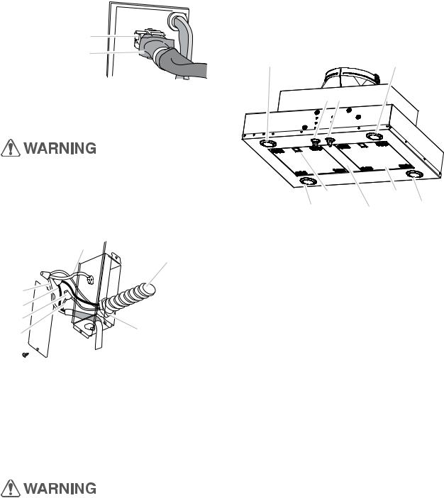
6.Remove knockout from the top of the vent hood and install a UL listed or CSA approved ½” (1.3 cm) strain relief.
7.Place the hood insert near its mounting position
and run the power supply cable through the strain relief intoterminalbox(enoughtomake connection).
8.Tighten the strain relief screws.
9.Using 2 or more people, lift the hood insert into hood cabinet.
10.Fasten the hood insert using four 5 x 45 mm screws to the hood cabinet and tighten securely.
Excessive weight hazard
Use two or more people to move and install hood insert. Failure to do so can result in back or other injury.
Upper Hood
Insert Motor Housings
4 mounting  screws
To install the single or dual Blower motor
1.To install blower motor assembly, slide the left mounting plate flange under the motor mounting bracket.
A
B |
A.Motor mounting bracket |
|
B.Mounting plate left flange |
2.Push the right end of the motor mounting plate down and snap it into the spring tab.
NOTE: The spring tab should be outside the slot in the mounting plate.
A
A. Motor mounting plate
B. Spring clip
3.Align mounting holes and install 6 x 16 mm bolts and 6.4 mm lock washers.
4.Attach power cord connector from the hood insert to connector on wiring box.
A
A. Bolt with lock washer
B. Mounting hole
B
A. Wiring Box Connector |
A |
|
B. Hood Insert Connector |
||
|
||
|
B |
Make Electrical Power Supply Connection to Hood Insert
Electrical Shock Hazard Disconnect power before servicing.
Replace all parts and panels before operating.
Failure to do so can result in death or electrical shock.
1.Disconnect power.
2.Locate terminal box inside of the hood insert.
|
G |
|
E |
A |
|
B |
|
C |
|
D |
F |
A.White wires
B.Black wires
C.UL listed wire connectors
D.Green, bare or yellow/green wires E.Home power supply
F.UL listed or CSA approved ¹⁄2” (1.3 cm) strain relief
G.Ground Wire tab
3.Use UL listed wire connectors and connect black wires
(B)together.
4.Use UL listed wire connectors and connect white wires
(A)together.
Complete Installation and
Check Operation
1.Install grease filters. See the “Cleaning” section.
2.Check operation of the Hood Insert blower and lights. See the “Hood Insert Use” section.
A A
B C
D E
A F A
A.Halogen lights
B.Halogen light switch
C.Blower control switche
D.Grease filter handle
E.Grease filter
F.Filter Spacer (Only for EAR628SS model)
3.If the hood insert does not operate, check to see whether a circuit breaker has tripped or a hous hold fuse has blown.
4.Disconnect power supply and check that the wiring is correct.
NOTE: To get the most efficient use from your new hood insert, read the “Hood Insert Use” section.
Electrical Shock Hazard Electrically ground blower.
Connect ground wire to green and yellow ground wire in terminal box.
Failure to do so can result in death or electrical shock.
5.Connect green (or bare) ground wire from home power supply to the green/yellow ground wire (D) in terminal box using UL listed wire connectors.
6.Install terminal box cover.
7.Check that all light bulbs are secure in their sockets.
8.Reconnect power.

Hood Insert Use
The hood insert is designed to remove smoke, cooking vapors and odors from the cooktop area. For best results, start the hood before cooking and allow it to operate several minutes after the cooking is complete to clear all smoke and odors from the kitchen.
The hood controls are located on the underside of the hood insert.
A. Light control |
B. Fan control |
Operating the light
Turn the light switch (A) to the left 1 position tu turn the light ON.
Turn the light switch (A) to the right 1 postion to turn the light OFF.
Operating the fan
The fan has 4 speeds. Rotate the fan switch (B) to the left to turn the fan to the ON position. Continue to rotate the switch to the desired fan speed.
To turn the fan OFF, rotate the fan speed (B) switch to the right to the OFF position.
WARNING: The internal blower motor of the hood is thermally protected against high temperatures.
If the hood insert is not turned on during the cooking process, high temperatures could be present inside the hood and the motor could not work until the temperature is safe. The hood insert should be turned on during cooking operations.
Cleaning
IMPORTANT: Clean the hood insert and grease filters frequently according to the following instructions. Replace grease filters before operating hood insert.
Exterior Surfaces:
To avoid damage to the exterior surface, do not use steel wool or soap-filled scouring pads.
Always wipe dry to avoid water marks.
Cleaning Method:
•Liquid detergent soap and water, or all-purpose cleaner.
•Wipe with damp soft cloth or nonabrasive sponge, then rinse with clean water and wipe dry.
Metal Grease Filter
The filters should be washed frequently. Place metal filters in dishwasher or hot detergent solution to clean.
Let filter dry thoroughly before replacing it.
Turn off fan and lights. Allow halogen lamp to cool.
1.Remove each filter by pulling the spring release handle and then pulling down the filter.
A
A.Spring Release Handle
2.Wash metal filters as needed in dishwasher or hot detergent solution.
3.Reinstall the filter by making sure the spring release handles are toward the front. Insert metal grease filter into upper track.
4.Pull the spring release handle down.
5.Push up on metal filter and release handle to latch into place.
Replacing the Halogen Lamps
Turn off the range hood and allow the halogen lamp to cool. To avoid damage or decreasing the life of the new bulb, do not touch bulb with bare fingers. Replace bulb, using tissue or wearing cotton gloves to handle bulb.
If new lamps do not operate, make sure the lamps are inserted correctly before calling service.
1.Disconnect power.
2. Push up on the lens and turn it counterclockwise.
3.Remove the bulb and replace it with a 120-volt, 50-watt maximum halogen bulb with a GU10 base. Turn it clockwise to lock it into place.
4.Repeat steps 2-3 for the other bulb if needed.
5.Reconnect power.
10
 Loading...