


Use, Care, and Installation Guide Guide d’utilisation, d’entretien et d’installation
Guía de instalación, uso y mantenimiento
GLIDE
Design Team Elica
READ AND SAVE THESE INSTRUCTIONS
LISEZ CES INSTRUCTIONS ET CONSERVEZ-LES LEA Y GUARDE ESTAS INSTRUCCIONES
LI3G8A ed 04/08 printed in Italy

EN |
Contents |
page |
2 |
FR |
Sommaire |
page |
14 |
ES |
Contenido |
página |
26 |
English |
|
|
|
Contents |
|
|
|
Important safety Notice ................................................................................................................................................................... |
|
3 |
|
Electrical & Installation requirements.............................................................................................................................................. |
|
4 |
|
Electrical requirements............................................................................................................................................................... |
|
4 |
|
Before installing the hood........................................................................................................................................................... |
|
4 |
|
List of Materials............................................................................................................................................................................... |
|
5 |
|
Parts supplied ............................................................................................................................................................................ |
|
5 |
|
Parts not supplied ...................................................................................................................................................................... |
|
5 |
|
Dimensions and Clearances ........................................................................................................................................................... |
|
6 |
|
Ducting Options and Examples....................................................................................................................................................... |
|
7 |
|
Venting methods ........................................................................................................................................................................ |
|
7 |
|
Preparation ................................................................................................................................................................................ |
|
7 |
|
Installation....................................................................................................................................................................................... |
|
|
8 |
Description of the hood & Controls ............................................................................................................................................... |
|
11 |
|
Controls.................................................................................................................................................................................... |
|
|
12 |
Maintenance ................................................................................................................................................................................. |
|
|
13 |
Cleaning................................................................................................................................................................................... |
|
|
13 |
Grease Filter ............................................................................................................................................................................ |
|
13 |
|
Replacing the light bulb............................................................................................................................................................ |
|
13 |
|
APPROVED FOR RESIDENTIAL APPLIANCES
FOR RESIDENTIAL USE ONLY
READ AND SAVE THESE INSTRUCTIONS
PLEASE READ ENTIRE INSTRUCTIONS BEFORE PROCEEDING. INSTALLATION MUST COMPLY WITH ALL LOCAL CODES.
IMPORTANT: Save these Instructions for the Local Electrical Inspector’s use. INSTALLER: Please leave these Instructions with this unit for the owner. OWNER: Please retain these instructions for future reference.
Safety Warning: Turn off power circuit at service panel and lock out panel, before wiring this appliance. Requirement: 120 V AC, 60 Hz. 15 or 20 A Branch Circuit
READ AND SAVE THESE INSTRUCTIONS
Important safety Notice
CAUTION
FOR GENERAL VENTILATING USE ONLY. DO NOT USE TO EXHAUST HAZARDOUS OR EXPLOSIVE MATERIALS OR VAPOURS.
WARNING
TO REDUCE THE RISK OF FIRE, ELECTRIC SHOCK, OR INJURY TO PERSONS, OBSERVE THE FOLLOWING:
A.Use this unit only in the manner intended by the manufacturer. If you have questions, contact the manufacturer.
B.Before servicing or cleaning the unit, switch power off at service panel and lock service panel disconnecting means to prevent power from being switched on accidentally. When the service disconnecting means cannot be locked, securely fasten a prominent warning device, such as a tag, to the service panel.
C.Installation Work and Electrical Wiring Must Be Done By Qualified Person(s) In Accordance With All Applicable Codes & Standards, Including Fire-rated Construction.
D.Sufficient air is needed for proper combustion and exhausting of gases through the flue (Chimney) of fuel burning equipment to prevent backdrafting. Follow the heating equipment manufacturers guideline and safety standards such as those published by the National Fire Protection Association (NFPA), the American Society for Heating, Refrigeration and Air Conditioning Engineers (ASHRAE), and the local code authorities.
E.When cutting or drilling into wall or ceiling, do not damage electrical wiring and other hidden utilities.
F.Ducted systems must always be vented to the outdoors.
WARNING
TO REDUCE THE RISK OF INJURY TO PERSONS, IN THE EVENT OF A RANGE TOP GREASE FIRE, OBSERVE THE FOLLOWING:
a)SMOTHER FLAMES with a close-fitting lid, cookie sheet, or other metal tray, then turn off the gas burner or the electric element. BE CAREFUL TO PREVENT BURNS. If the flames do not go out immediately, EVACUATE AND CALL THE FIRE DEPARTMENT.
b)NEVER PICK UP A FLAMING PAN - you may be burned.
c)DO NOT USE WATER, including wet dishcloths or towels - a violent steam explosion will result.
d)Use an extinguisher ONLY if:
1)You know you have a class ABC extinguisher, and you already know how to operate it.
2)The fire is small and contained in the area where it started.
3)The fire department is being called.
4)You can fight the fire with your back to an exit.
OPERATION
a. Always leave safety grills and filters in place. Without these components, operating blowers could catch onto hair, fingers and loose clothing.
The manufacturer declines all responsibility in the event of failure to observe the instructions given here for installation, maintenance and suitable use of the product. The manufacturer further declines all responsibility for injury due to negligence and the warranty of the unit automatically expires due to improper maintenance.
CAUTION
To reduce risk of fire and to properly exhaust air, be sure to duct air outside - do not vent exhaust air into spaces within walls, ceilings, attics, crawl spaces, or garages.
WARNING
TO REDUCE THE RISK OF FIRE, USE ONLY METAL DUCT WORK.
Install this hood in accordance with all requirements specified.
WARNING
To Reduce The Risk Of Fire Or Electric Shock, Do Not Use This Hood With Any External Solid State Speed Control Device.
WARNING
TO REDUCE THE RISK OF A RANGE TOP GREASE FIRE.
a)Never leave surface units unattended at high settings. Boilovers cause smoking and greasy spillovers that may ignite. Heat oils slowly on low or medium settings.
b)Always turn hood ON when cooking at high heat or when flambeing food (I.e. Crepes Suzette, Cherries Jubilee, Peppercorn Beef Flambe’).
c)Clean ventilating fans frequently. Grease should not be allowed to accumulate on fan or filter.
d)Use proper pan size. Always use cookware appropriate for the size of the surface element.
3
Electrical & Installation requirements
Electrical requirements
IMPORTANT
Observe all governing codes and ordinances.
It is the customer’s responsibility:
To contact a qualified electrical installer.
To assure that the electrical installation is adequate and in conformance with National Electrical Code, ANSI/NFPA 70
— latest edition*, or CSA Standards C22.1-94, Canadian Electrical Code, Part 1 and C22.2 No.0-M91 - latest edition** and all local codes and ordinances.
If codes permit and a separate ground wire is used, it is recommended that a qualified electrician determine that the ground path is adequate.
Do not ground to a gas pipe.
Check with a qualified electrician if you are not sure range hood is properly grounded.
Do not have a fuse in the neutral or ground circuit.
Before installing the hood
1.For the most efficient air flow exhaust, use a straight run or as few elbows as possible.
CAUTION: Vent unit to outside of building, only.
2.At least two people are necessary for installation.
3.Fittings material is provided to secure the hood to most types of walls/ceilings, consult a Qualified Installer, check if they perfectly fit with your cabinet/wall.
4.Do not use flex ducting.
5.COLD WEATHER installations should have an additional backdraft damper installed to minimize backward cold air flow and a nonmetallic thermal break to minimize conduction of outside temperatures as part of the ductwork. The damper should be on the cold air side of the thermal break.
The break should be as close as possible to where the ducting enters the heated portion of the house.
IMPORTANT
Save Installation Instructions for electrical inspector’s use.
The range hood must be connected with copper wire only.
The range hood should be connected directly to the fused disconnect (Or circuit breaker) box through metal electrical conduit.
Wire sizes must conform to the requirements of the National Electrical Code ANSI/NFPA 70 — latest edition*, or CSA Standards C22.1-94, Canadian Electrical Code Part 1 and C22.2 No. 0-M91 - latest edition** and all local codes and ordinances.
A U.L.- or C.S.A.-listed conduit connector must be provided at each end of the power supply conduit (at the range hood and at the junction box).
Copies of the standards listed may be obtained from:
*National Fire Protection Association Batterymarch Park Quincy, Massachusetts 02269
**CSA International 8501 East Pleasant Valley Road Cleveland, Ohio 44131-5575
6.Make up air: Local building codes may require the use of Make-Up Air Systems when using Ducted Ventilation Systems greater than specified CFM of air movement. The specified CFM varies from locale to locale. Consult your HVAC professional for specific requirements in your area.
4
List of Materials
Parts supplied
•Blower unit housing
•Hood canopy
•Stainless steel mesh filter
•Halogen light bulb x 2
•Hardware Packet: Transition
Allen Wrench Lower bracket x 2 Upper Bracket x 2
Use, Care and Installation Guide Template
Cloth
2,9x9,5 screws x 2 (To attach the transition)
4,5x16 screws x 4 (2 to attach the drawer to the bottom
of the cabinet + 2 to attach the deflector on top of the cabinet ceiling)
5x18 screws x 4 (Upper/lower brackets adjusting screws)
3,5x9,5 x 4 (For definitive attaching of upper/lower brackets).
5
Parts not supplied
•Duct, conduit and all tools required for installation.
•Remote Control
•Ductless Recirculating Kit
To be used only in the Ductless (Recirculating) version
includes: charcoal filter, charcoal filter support and fixing bracket, deflector
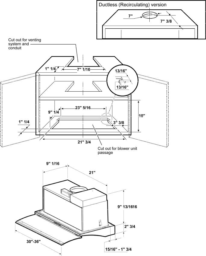
Dimensions and Clearances
6
Ducting Options and Examples
Closely follow the instructions set out in this manual.
All responsibility, for any eventual inconveniences, damages or fires caused by not complying with the instructions in this manual, is declined.
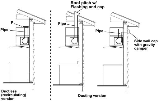
Venting methods
The hood is equipped with a transition B for discharge of fumes to the outside (Ducting version).
Should it not be possible to discharge cooking fumes and vapour to the outside, the hood can be used in the Ductless (Recirculating) version. Attach a charcoal filter on the internal side of the metal filter and the deflector F directly on the transition (Cabinet without ceiling) or at the top of the cabinet. Fumes and vapors are recycled directly through the deflector F (Cabinet without ceiling) or by means of a duct connected to the transition B and the deflector F.
NOTE: For ductless (Recirculating) version only: purchase the Ductless Recirculating Kit. Minimum Duct Size (Ducting/Ductless version): 6" Round Pipe.
Preparation
This hood is designed to be installed inside a cabinet (only Blower unit housing) and fixed at the bottom of the cabinet, check that the cabinet, its bottom, the hanging system of the cabinet and the wall where cabinet is installed is strong enough to support the hood.
The inside of the cabinet should be accessible.
However, a qualified technician must verify suitability of the materials in accordance with the type of cabinet. We suggest to mount the cabinet onto the wall after having installed the hood.
Before making cutouts, make sure there is proper clearance.
NOTE: For ductless (recirculating) version only: Check that there is enough clearance from ceiling and deflector once this last has been mounted to let an easy recirculation of air.
Hood installation height above cooktop is the users preference. The lower the hood is above the cooktop, the more efficient the capturing of cooking odors, grease and smoke.
CAUTION: FOR GAS RANGES INSTALLATION: MOUNT THIS HOOD SO THAT THE BOTTOM EDGE IS NOT LESS THAN 24" (61 CM) ABOVE THE COOKING SURFACE.
FOR ELECTRIC RANGES INSTALLATION: MOUNT THIS HOOD SO THAT THE BOTTOM EDGE IS NOT LESS THAN 32" (81 cm) ABOVE THE COOKING SURFACE.
Check your ceiling height and the hood height maximum before you select your hood.
7
Installation
1.If possible, disconnect and move freestanding or slide-in range from cabinet opening to provide easier access to rear wall. Otherwise put a thick, protective covering over countertop, cooktop or range to protect from damage and debris. Select a flat surface for assembling the unit. Cover that surface with a protective covering and place all canopy hood parts and hardware in it.
2.Remove the metal filter (see paragraph "Maintenance") top access the inside of the range hood.
3.Perform any necessary cutout on cabinet and wall as per "Dimensions and clearances" paragraph for range hood mounting and for vent system and conduit passage. Use the supplied template to perform the cut out on cabinet.
Tape the template on the bottom of the cabinet, check that printed arrows match with the front edge of the cabinet (without considering the cabinet door).
Cut as indicated.
4.Install the vent system before the range hood. See „Venting methods“ and „Dimensions and clearance“ paragraphs.
Note - for Ductless - recirculating - installations: Purchase the Ductless recirculating kit
Cabinet without ceiling:
Vent system is not required.
Cabinet with ceiling:
A 6" section of duct may be required to connect transition to deflector.
5.Install a conduit long enough to reach the junction box. Run wires through hole according the National Electrical Code or CSA Standards and local codes and ordinances.
There must be enough power supply cable from the fused disconnect (or circuit breaker) box to make the connection in the hood’s Junction box/es.
Use caulking to seal all openings on wall.
Do Not turn on power until installation is completed.
8
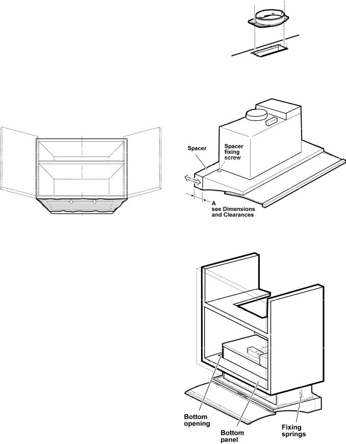
6. Fit the transition on top of the hood.
7.Regulate the rear spacer to cover the clearance on the rear side once the hood has been installed (see also paragraph "Dimensions and clearances") and fix it with two screws (one per side).
8.Fit the blower unit housing inside the cabinet through the bottom opening.
Check that fixing springs goes over the bottom panel..

9.Apply two brackets (one per side) to the blower unit housing.........
....... lock in place (check that each bracket , once in position, is flush to the front side of the blower unit housing) tighten the side fixing screws (two per brackets) and, from the inside of the hood, fix with one screw each then .......
.......apply the two bigger brackets (lower brackets) under
the first two and....
..... tighten securely the two screws on upper brackets, check that blower housing is now well blocked, then, from the inside of the hood, fix definitively the lower brackets with one screw each.
10. Refinish the installation to cabinet with two fixing screws.
For Ductless (recirculating) installations
Cabinet without ceiling ONLY:
Install the deflector (available as an extra kit) on the transition - snap into place.
11.Connect ducting to transition. Seal with duct tape.
Do not use duct smaller than the transition. For Ductless - recirculating - installations:
Cabinet with ceiling ONLY:
provide and install a section of duct long enough to connect hood transition to deflector once this has been installed onto the cabinet ceiling (the deflector is available as an extra kit).
9
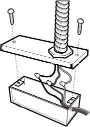
12. Electrical connection
WARNING
Electrical Shock Hazard
Warning: Turn off power circuit at the service panel before wiring this unit.
120 VAC, 15 or 20 Amp circuit required.
ELECTRICAL GROUNDING INSTRUCTIONS
THIS APPLIANCE IS FITTED WITH AN ELECTRICAL JUNCTION BOX WITH 3 WIRES, ONE OF WHICH (GREEN/YELLOW) SERVES TO GROUND THE APPLIANCE. TO PROTECT YOU AGAINST ELECTRIC SHOCK, THE GREEN AND YELLOW WIRE MUST BE CONNECTED TO THE GROUNDING WIRE IN YOUR HOME ELECTRICAL SYSTEM, AND IT MUST UNDER NO CIRCUMSTANCES BE CUT OR REMOVED.
Failure to do so can result in death or electrical shock.
Remove the knockout and the Junction box cover and install the conduit connector (cULus listed) in junction box.
Run 3 wires; black, white and green ,according to the National Electrical Code and local codes and ordinances, in 1/2" conduit from service panel to junction box.
Connect black wire from service panel to black or red in junction box, white to white and green to green-yellow.
Close and secure junction box cover.
13.For Ductless (recirculating) installations
Install one charcoal filter (available as an extra kit).
14.Check all light bulbs to make sure they are secure in their sockets.
Turn power (On) in service panel. Check lights and blower operation.
15.Install filter.
If range hood does not operate:
•Check that the circuit breaker is not tripped or the house fuse blown.
•Disconnect power supply. Check that wiring is correct.
10
Description of the hood & Controls
1Control panel
2Grease filter
3Grease filter release handle
4Halogen lamp (position and nr. of lamps may vary)
5Sliding Glass
6Hood canopy
11
Controls
Use the high suction speed in cases of concentrated kitchen vapours. It is recommended that the cooker hood suction is switched on for 5 minutes prior to cooking and to leave in operation during cooking and for another 15 minutes approximately after terminating cooking.
Description of control panel
A B C D E F
A-Lighting: dim lighting / full lighting /off (loop control) - Works even with hood in stand by and/or drawer closed.
B-Set Fan in Stand by (LED on the lower side of the display ON).
C-ON/OFF Timer for selected speed (visualizes the speed selected and flashing LED on the lower side of the display).
This knob permits the operation of the cooker hood for a established period:
20 minutes if the speed selected is 1
15 minutes if the speed selected is 2
10 minutes if the speed selected is 3
5 minutes if the boost speed P is selected.
D-Display showing: fan speed (1-2-3-P), filter saturation
indicator (F for metal filter, C for charcoal filter)
Note: if in posses of the Remote Control (see paragraph "List of Part and Accessories") the display shows a flashing "b" this to indicate that the remote control battery must be replaced.
When the led in the lower right side is on, it indicates that the cooker hood is ready for operation (“standby” position), the flashing LED indicates that the timer has been activated for selected speed.
Warning!
The Charcoal filter saturation function is not activated. In order to activate the charcoal filter saturation indicator, press buttons E and F simultaneously for 3 seconds. Initially, only letter F will be displayed, then after the 3 seconds have passed, letter C will be displayed as well, indicating that the carbon filter saturation control system is active.
To switch off the system, re-press the same two buttons: letter C appear on display and after 3 seconds it disappears and the device will be switched off.
E-Knob to decrease the speed: from boost speed P to speed level 1.
F-Knob to increase (standby) speed to boost speed P. Attention! Boost speed P lasts 5 minutes after which the cooker hood automatically sets the speed to level 2 (suction power).
12
Controlling the range hood with sliding glass:
Closing the glass, all selected speed and lights switched off. Hood retains last speed (except P-boost-speed) setting when glass is closed and re-opened.
If the hood fails to operate correctly, briefly disconnect it from the mains power supply for almost 5 sec. by pulling out the plug. Then plug it in again and try once more before contacting the Technical Assistance Service.
Warning!
Always press the fan off button A before disconnecting the hood from the mains supply.
Reset filter saturation signal
Press knob B for about 3 seconds.
The letter F and/or C will disappear from the display.
 Loading...