


ELN142S1
1
Use, Care, and
Installation Guide
Guide
d’utilisation,
d’entretien et
d’installation
Guía de
instalación, uso y
mantenimiento
READ AND SAVE THESE
INSTRUCTIONS
LISEZ CES
INSTRUCTIONS ET
CONSERVEZ-LES
LEA Y CONSERVE
ESTAS INSTRUCCIONES
LIB0138269A
Printed in Mexico
01/19
Models: ELN630S1
ELN136S1
ELN142S1
ELN148SS

2

3
ENGLISH
Contents
Important safety notice................................................................................................................................................................................................. 4
Electrical & installation requirements ................................................................................................................................................................ 5
Before installing the hood ...................................................................................................................................................................................... 5
Product dimensions ....................................................................................................................................................................................................... 5
List of materials................................................................................................................................................................................................................. 6
Parts supplied .............................................................................................................................................................................................................. 6
Parts not supplied ...................................................................................................................................................................................................... 6
Ducting options and examples.................................................................................................................................................................................. 7
Installation ......................................................................................................................................................................................................................... 8
Electrical connection................................................................................................................................................................................................ 9
Complete the installation........................................................................................................................................................................................ 10
Description of the hood................................................................................................................................................................................................. 10
Control.................................................................................................................................................................................................................................. 11
Maintenance ...................................................................................................................................................................................................................... 12
Warranty ........................................................................................................................................................................................................................... 13
APPROVED FOR RESIDENTIAL APPLIANCES
FOR RESIDENTIAL USE ONLY
READ AND SAVE THESE INSTRUCTIONS
PLEASE READ ENTIRE INSTRUCTIONS BEFORE PROCEEDING.
INSTALLATION MUST COMPLY WITH ALL LOCAL CODES.
IMPORTANT: Save these Instructions for the Local Electrical Inspector’s use.
INSTALLER: Please leave these Instructions with this unit for the owner.
OWNER: Please retain these instructions for future reference.
Safety Warning: Turn o power circuit at service panel and lock out panel, before wiring this appliance.
Requirement: 120 V AC, 60 Hz. 15 or 20 A Branch Circuit.

4
I
IMPORTANT SAFETY NOTICE
I CAUTION
FOR GENERAL VENTILATING USE ONLY. DO NOT USE TO
EXHAUST HAZARDOUS OR EXPLOSIVE MATERIALS OR
VAPOURS.
I WARNING
TO REDUCE THE RISK OF FIRE, ELECTRIC SHOCK, OR
INJURY TO PERSONS, OBSERVE THE FOLLOWING:
A. Use this unit only in the manner intended by the
manufacturer. If you have questions, contact the
manufacturer.
B. Before servicing or cleaning the unit, switch power o
at service panel and lock service panel disconnecting
means to prevent power from being switched on
accidentally.
When the service disconnecting means cannot be
locked, securely fasten a prominent warning device,
such as a tag, to the service panel.
C. Installation work and electrical wiring must be done by
qualified person(s) in accordance with all applicable
codes & standards, including fire-rated construction.
D. Sucient air is needed for proper combustion and
exhausting of gases through the flue (Chimney) of fuel
burning equipment to prevent back- drafting.
Follow the heating equipment manufacturers guideline
and safety standards such as those published by the
national fire protection association (NFPA), the american
society for heating, refrigeration and air conditioning
engineers (ASHRAE), and the local code authorities.
E. When cutting or drilling into wall or ceiling, do not
damage electrical wiring and other hidden utilities.
F. Ducted systems must always be vented to the outdoors.
I CAUTION
To reduce risk of fire and to properly exhaust air, be sure to
duct air outside - do not vent exhaust air into spaces within
walls, ceilings, attics, crawl spaces, or garages.
I WARNING
TO REDUCE THE RISK OF FIRE, USE ONLY METAL DUCT
WORK.
Install this hood in accordance with all requirements specified.
I WARNING
To reduce the risk of fire or electric shock, do not use this
hood with any external solid state speed control device.
I WARNING
TO REDUCE THE RISK OF A RANGE TOP GREASE FIRE.
a) Never leave surface units unattended at high settings.
Boilovers cause smoking and greasy spillovers that may
ignite. Heat oils slowly on low or medium settings.
b) Always turn hood ON when cooking at high heat or when
flambeing food (I.e. Crepes Suzette, Cherries Jubilee,
Peppercorn Beef Flambe’).
c) Clean ventilating fans frequently. Grease should not be
allowed to accumulate on fan or filter.
d) Use proper pan size. Always use cookware appropriate
for the size of the surface element.
I WARNING
TO REDUCE THE RISK OF INJURY TO PERSONS, IN THE
EVENT OF A RANGE TOP GREASE FIRE, OBSERVE THE
FOLLOWING:
a
a) SMOTHER FLAMES with a close-fitting lid, cookie sheet,
or other metal tray, then turn o the gas burner or the
electric element. BE CAREFUL TO PREVENT BURNS. If the
flames do not go out immediately, EVACUATE AND CALL
THE FIRE DEPARTMENT.
b) NEVER PICK UP A FLAMING PAN - you may be burned.
c) DO NOT USE WATER, including wet dishcloths or towels -
a violent steam explosion will result.
d) Use an extinguisher ONLY if:
1) You know you have a class ABC extinguisher, and
you already know how to operate it.
2) The fire is small and contained in the area where it
started.
3) The fire department is being called.
4) You can fight the fire with your back to an exit.
e) Ducted fans must always be vented to the outdoor.
a
Based on “Kitchen Fire Safety Tips” published by NFPA.
I CAUTION
Automatically Operated Device - To reduce the risk of
Injury disconnect from power supply before servicing.
I WARNING
To Reduce The Risk Of Fire And Electric Shock, Install This Rangehood Only With Integral, In Line, and External Blower Models
Rated Maximum 7.6 A/ 913 W Or Integral Blowers Manufactured by Elica (for model references, see optional accessories table).
Integral Blower
(already included
with the hood)
In Line
Blower Kit 1200
KIT0154387
External
Blower Kit 1200
KIT0153054
HOOD MODEL A W A W A W
ELN630S1 3.9 463 7.65 453.9 7.42 884
ELN136S1 7.6 913 7.6 913 7.37 884
ELN142S1 7.6 913 7.6 913 7.37 884
ELN148SS 7. 6 913 7.6 913 7.37 884

5
ELECTRICAL & INSTALLATION REQUIREMENTS
IMPORTANT
Observe all governing codes and ordinances.
It is the customer’s responsibility:
• To contact a qualified electrical installer.
• To assure that the electrical installation is adequate and in
conformance with National Electrical Code, ANSI/NFPA 70
— latest edition*, or CSA Standards C22.1-94, Canadian
Electrical Code, Part 1 and C22.2 No.0-M91-latest edition**
and all local codes and ordinances.
• If codes permit and a separate ground wire is used, it is
recommended that a qualified electrician determine that
the ground path is adequate.
• Do not ground to a gas pipe.
• Check with a qualified electrician if you are not sure range
hood is properly grounded.
• Do not have a fuse in the neutral or ground circuit.
IMPORTANT
• Save Installation Instructions for electrical inspector’s use.
• The range hood must be connected with copper wire only.
• The range hood should be connected directly to the fused
disconnect (Or circuit breaker) box through metal
electrical conduit.
• Wire sizes must conform to the requirements of the
National Electrical Code ANSI/NFPA 70 — latest edition*,
or CSA Standards C22.1-94, Canadian Electrical Code Part
1 and C22.2 No. 0-M91 - latest edition** and all local codes
and ordinances.
• A U.L.- or C.S.A.-listed conduit connector must be
provided at each end of the power supply conduit (at the
range hood and at the junction box).
Copies of the standards listed may be obtained from:
* National Fire Protection Association Batterymarch Park Quincy,
Massachusetts 02269
** CSA International 8501 East Pleasant Valley Road Cleveland,
Ohio 44131-5575
BEFORE INSTALLING THE HOOD
1 For the most ecient air flow exhaust, use a straight run
or as few elbows as possible.
CAUTION: Vent unit to outside of building, only.
2 At least two people are necessary for installation.
3 Fittings material is provided to secure the hood to most
types of walls/ceilings, consult a Qualified Installer,
check if they perfectly fit with your cabinet/wall.
4 Do not use flex ducting.
5 COLD WEATHER installations should have an additional
backdraft damper installed to minimize backward cold air
flow and a nonmetallic thermal break to minimize
conduction of outside temperatures as part of the
ductwork. The damper should be on the cold air side of
the thermal break.
The break should be as close as possible to where the
ducting enters the heated portion of the house.
6 Make up air: Local building codes may require the use of
Make-Up Air Systems when using Ducted Ventilation
Systems greater than specified CFM of air movement.
The specified CFM varies from locale to locale. Consult
your HVAC professional for specific requirements in your
area.
PRODUCT DIMENSIONS
A
B
C
E
F
G
D*
Models
ELN630S1 ELN136S1 ELN142S1 ELN148SS
A 30” (76.2 cm) 36” (91.4 cm) 42” (106.7 cm) 48” (122 cm)
B 24” (61 cm)
C Max: 47
5
⁄8” (120.9 cm)
Min: 30” (76.2 cm)
D* Max: 84” (213.5 cm)
Min: 51
1
⁄4” (130.2 cm)
E 13
2
⁄16” (33.2 cm)
F 10
5
⁄8” (27 cm)
G 8” (20.3 cm)
* with Long Chimney Extension Kit
CC
6
LIST OF MATERIALS
Removing the packaging.
I CAUTION
Remove carton carefully, Wear gloves to protect against sharp edges.
I WARNING
Remove the protective film covering the product before putting into operation.
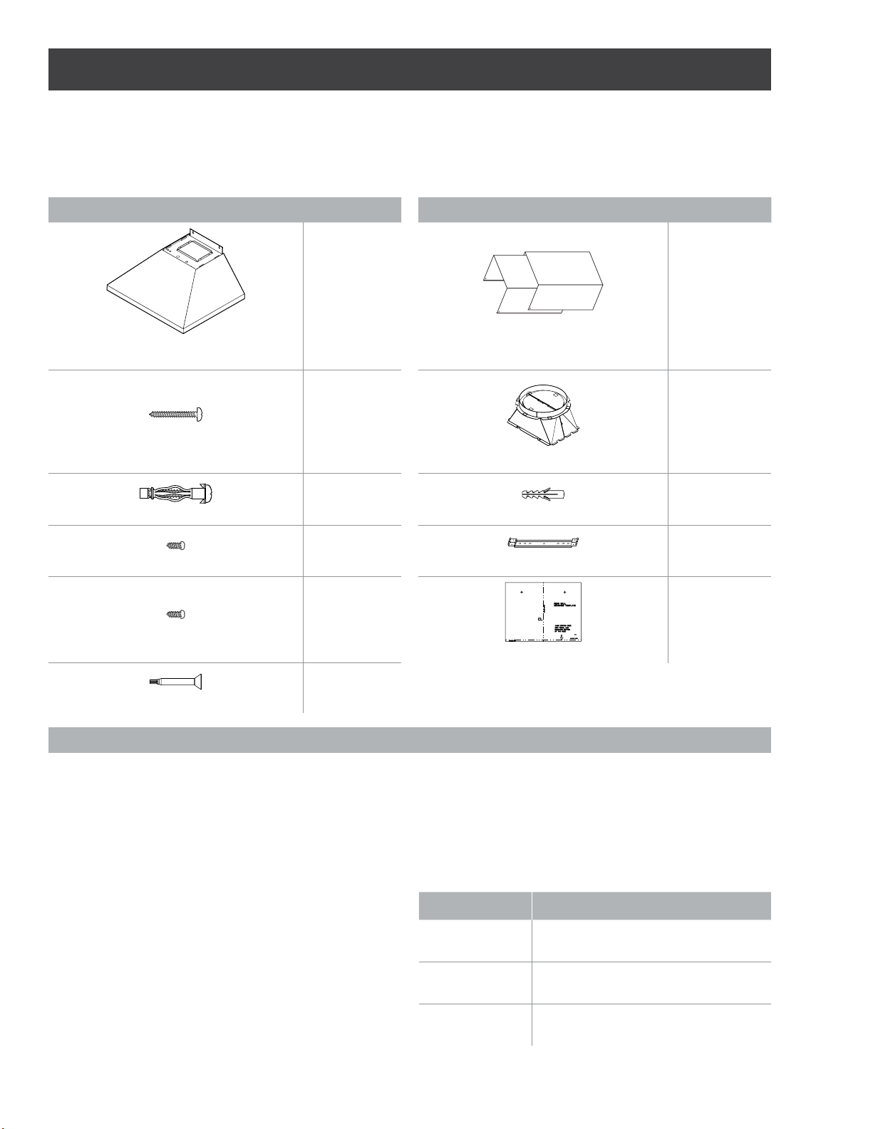
Supplied Part Pieces Supplied Part Pieces
Hood assembly and
LED lamps already installed
1
Duct covers
2
5x45 mm
6
8” round air transition
1
5.4x75 mm
4
8x40 mm
2
3.5x9.5 mm
4
Duct cover bracket
1
4.2x8 mm
4
Mounting template
1
Torx 20 adapter
1
Parts no supplied
Tools/Materials required
• Level
• Drill
• 1
1
⁄4” (3.2 cm),
1
⁄8” (3.2 mm), and
1
⁄16” (4.8 mm) drill bits
• Pencil
• Wire stripper or utility knife
• Tape measure or ruler
• Pliers
• Caulking gun and weatherproof caulking compound
• Jigsaw or keyhole saw
• Metal snips
• Screwdrivers:
- Flat-blade
- Phillips
- Torx 10
Parts needed
• Home power supply cable
• 1 - ½” (12.7 mm) UL listed or CSA approved strain relief
• 3 UL listed wire connectors
• 1 wall or roof cap
• Metal vent system
Optional accessories and consumable parts
KIT # Part
Long Chimney
Extension
KIT02785
in Line Blower
1200 Kit
KIT0154387
External Blower
1200 Kit
KIT0153054
7
Ducting options
Closely follow the instructions set out in this manual.
All responsability, for any eventual inconveniences, damages or fires caused by not complying with the instructions in this
manual, is declined.
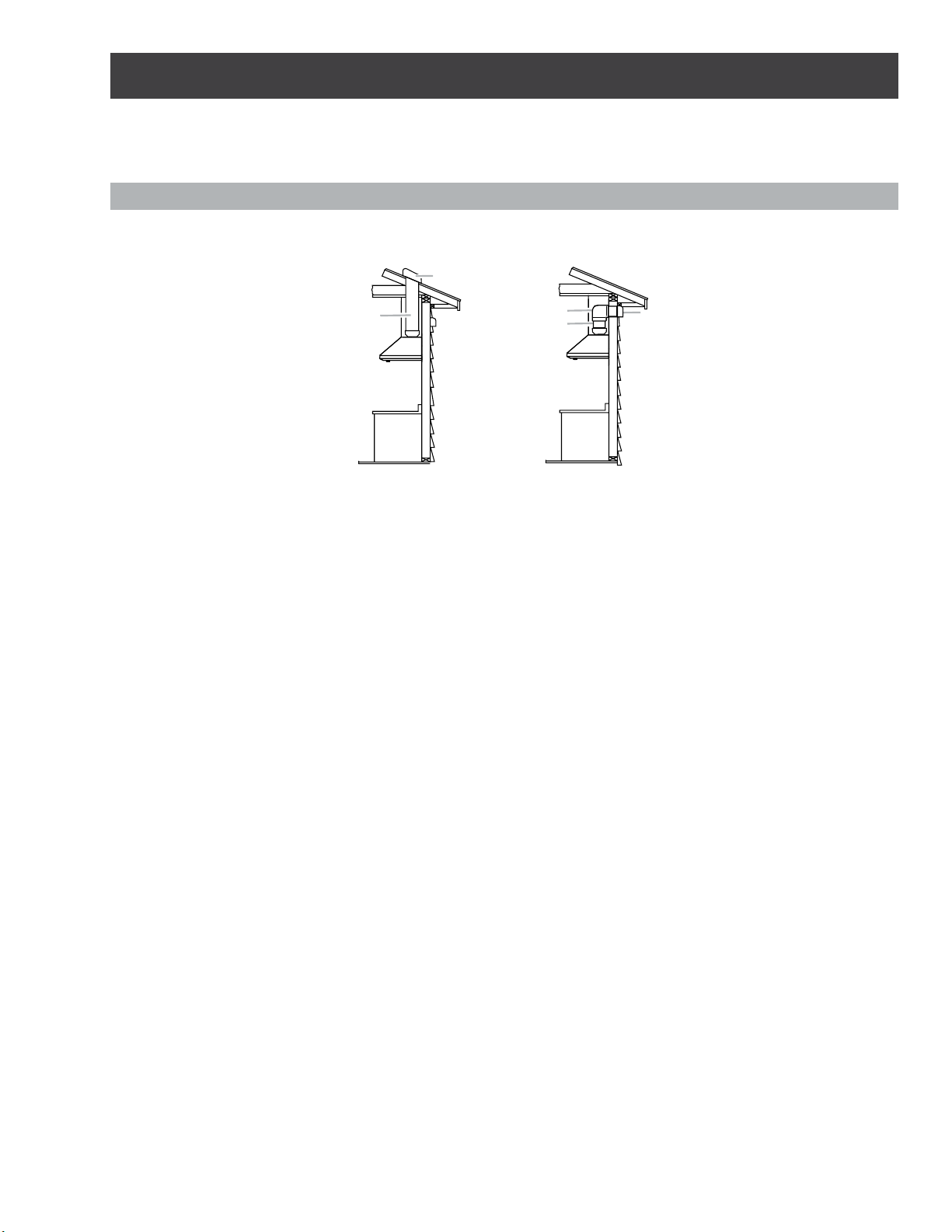
Ducting version
The hood is equipped with an 8” (20.3 cm) round transition for discharge of fumes to the outside.
Roof Venting Wall Venting
A
B
A
C
B
A. Roof cap
B. 8” (20.3 cm) round vent
A. Wall cap
B. 8” (20.3 cm) round vent
Preparation
Do not cut a joist or stud unless absolutely necessary. If a joist
or stud must be cut, then a supporting frame must be
constructed.
Fittings material is provided to secure the hood to most types
of walls/ceilings.
However, a qualified technician must verify suitability of the
materials in accordance with the type of wall/ceiling.
Before making cutouts, make sure there is proper clearance
within the ceiling or wall for exhaust vent.
Recommended installation height:
Hood installation height above cooktop is the users preference.
The lower the hood is above the cooktop, the more efficient
the capturing of cooking odors, grease and smoke.
I CAUTION
For gas cooktop & range installations: Mount the hood so the
bottom is at least 30” (76.2 cm) above the cooking surface.
For electric/induction cooktop & range installations: Mount the
hood so the bottom is at least 24” (61 cm) above the cooking
surface.
There is no maximum mounting height, however, we recom-
mend mounting the hood no greater than 36” (91.4 cm) above
the cooking surface. For every inch (2.54 cm) above 36” (91.4
cm), fume and moisture capture eciency diminishes at an in-
creasing rate and may not deliver an acceptable level of venti-
lating performance.
This hood is intended for household use.
PLEASE READ THE INSTALLATION MANUAL FOR SPECIFIC
APPLICATION. Check your ceiling height and hood height
before selecting your hood.
8
Installation
Prepare location
• It is recommended that the vent system be installed before
hood is installed.
• Before making cutouts, make sure there is proper clearance
within the ceiling or wall for exhaust vent.
• Check your ceiling height and the hood height maximum
before you select your hood.
1 Disconnect power.
2 Determine which venting method to use: roof, wall, or
nonvented.
3 Select a flat surface for assembling the range hood.
Place covering over that surface.
I WARNING
TO REDUCE THE RISK OF FIRE, ELECTRIC SHOCK, OR
INJURY TO PERSONS, OBSERVE THE FOLLOWING.
4 Using 2 or more people, lift range hood onto covered
surface.
Mounting the duct cover bracket
1 Determine and mark the centerline on the wall where the
canopy hood will be installed. Disconnect power.
2 Select a mounting height between a minimum of 24”
(61 cm) for an electric cooking surface, a minimum of
30” (76.2 cm) for a gas cooking surface, and a suggested
maximum of 36” (91.4 cm) above the range to the bottom
of the hood.
Mark a reference line on the wall.
3 Tape template in place, aligning the template centerline
and bottom of template with hood bottom line and with
the centerline marked on the wall.
A
C
B
A. Centerline
B. Fastener locations
C. Mounting height reference (hood bottom line)
4 Mark centers of the fastener locations through the
template to the wall.
IMPORTANT: All screws must be installed into wood.
If there is no wood to screw into, additional wall framing
supports may be required.
5 Remove the template.
6 Drill
3
⁄16” (4.8 mm) pilot holes at all locations where screws
are being installed into wood.
7 Install the 2 - 5 x 45 mm mounting screws. Leave a
1
⁄4”
(6.4 mm) gap between the wall and the back of the screw
head to slide range hood into place.
1
⁄4”
(6.4 mm)
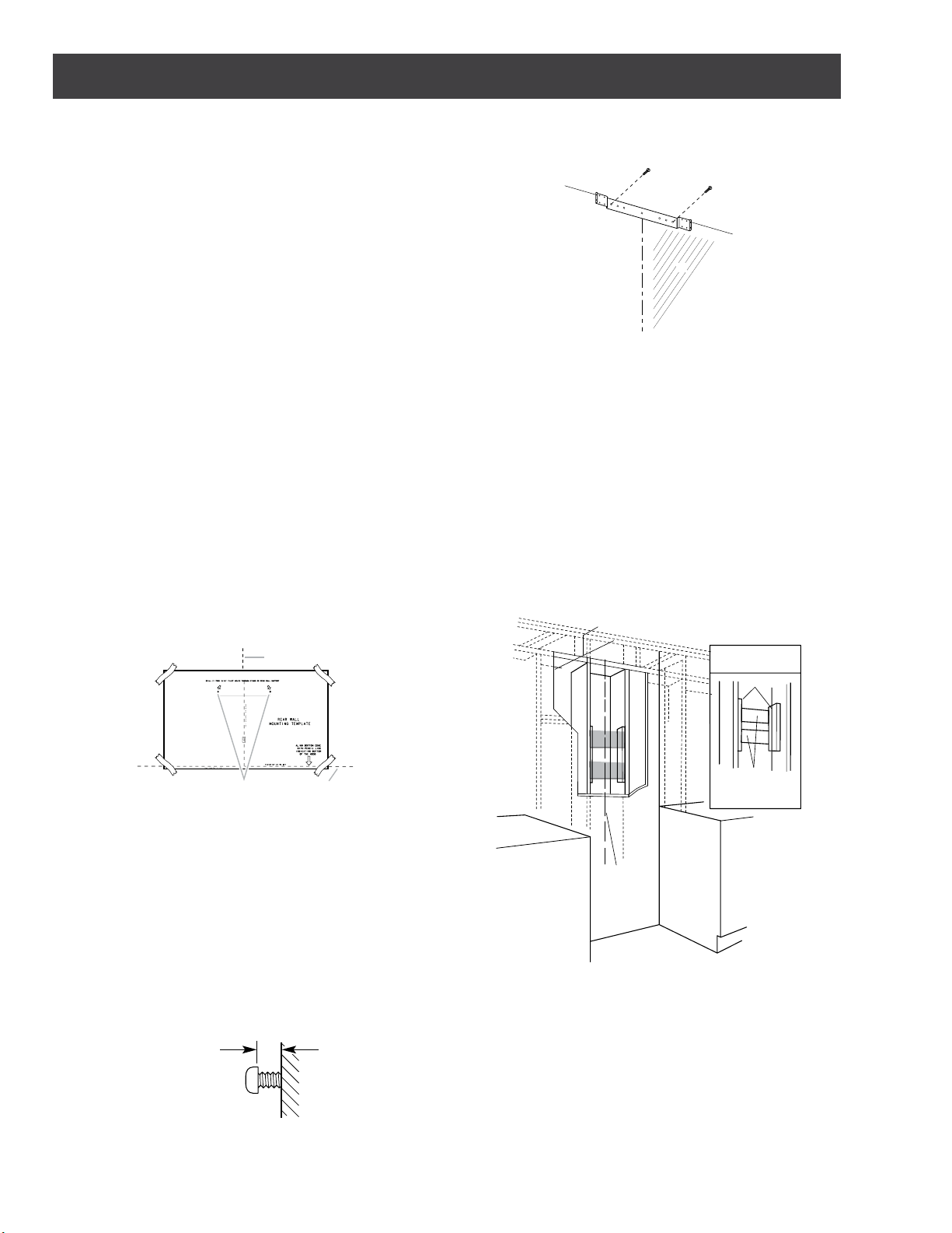
Vent cover bracket installation
1 Attach vent cover bracket to wall flush to the ceiling using
2 - 5 x 45 mm screws.
A
C
B
A. Ceiling
B. Wall
C. Centerline
Install framing for hood support
• If drywall is present, mark the screw hole locations.
• Cut away enough drywall to expose 2 vertical studs at the
holes location indicated by the template.
Install two horizontal supports at least 4 x 2” between two
wall studs at the bottom and upper mounting holes
installation location.
• The horizontal support must be flush with the room side
of the studs.
• Use cleats behind both sides of the support to secure to
wall studs.
• Reinstalll drywall and refinish
IMPORTANT- Framing must be capable of supporting 100 lbs.
8½” min. opening for ductwork
View from rear
cleats
1” x 6” min
Mounting
Support
Centerline of
installation
space
Complete preparation
1 Determine and make all necessary cuts in the wall for the
vent system. Install the vent system before installing the
hood. See “Venting Requirements” section.
2 Determine the required height for the home power supply
cable and drill a 1¼” (3.2 cm) hole at this location.
3 Run the home power supply cable according to the
National Electrical Code or CSA Standards and local codes
and ordinances. There must be enough ½” conduit and
wires from the fused disconnect (or circuit breaker) box to
make the connection in the hood’s electrical terminal box.
NOTE: Do not reconnect power until installation is complete.
4 Use caulk to seal all openings.
9
Install range hood
1 Using 2 or more people, hang range hood on 2 mounting
screws through the mounting slots on back of hood.
A
C
B
A. Mounting screws
B. Mounting slots
C. Lower mounting screws
1
2 Mark with a pencil the lower mounting holes location.
3 Uninstall the hood assembly, and drill
3
⁄16” (4.8 mm) pilot
holes at marked locations.
4 Hang the range hood again on 2 upper mounting screws.
5 Level the range hood and tighten upper mounting screws.
6 Install 2 - 5 x 45 mm lower mounting screws and tighten.
Use the optional wall anchors if needed.
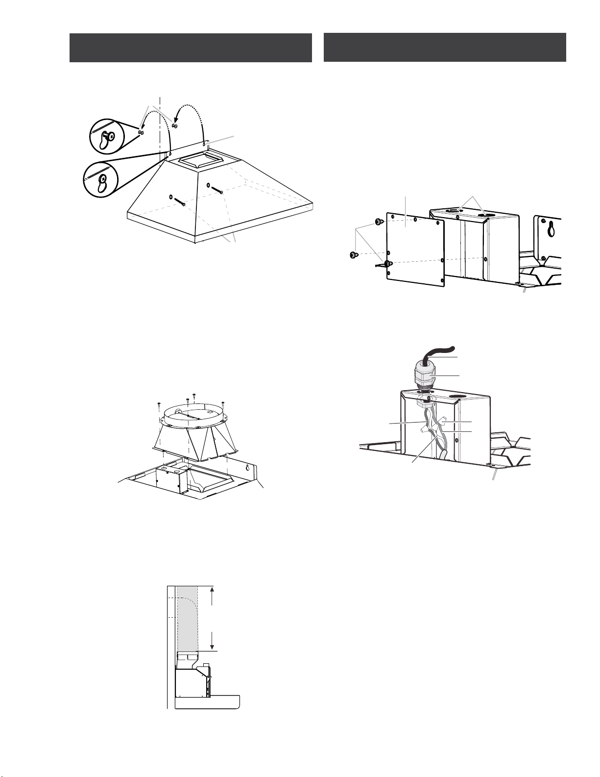
Connect vent system
1 Install transition on top of hood (if removed for shipping)
with 2 - 3.5 x 9.5 mm sheet metal screws.
A. Vent transition
B. 3.5 x 9.5 mm screw
For vented installations only:
1 Fit vent system over the exhaust outlet.
2 Measure from the bottom of the air deflector to the
bottom of the hood outlet. Cut the ductwork at the
measured dimension.
Dimension
to measure
Roof outlet
Wall
outlet
3 Seal connection with clamps.
4 Check that back draft dampers work properly.
Electrical connection
I WARNING
ELECTRICAL SHOCK HAZARD.
I WARNING
DISCONNECT POWER BEFORE SERVICING.
REPLACE ALL PARTS AND PANELS BEFORE OPERATING.
FAILURE TO DO SO CAN RESULT IN DEATH OR
ELECTRICAL SHOCK.
1 Disconnect power.
2 Remove terminal box cover.
3 Remove the knockout in the terminal box cover and install
a UL listed or CSA approved
1
⁄2” strain relief.
B A
C
A. Knockout
B. Junction box cover
C. Junction box cover screws
4 Run home power supply cable through strain relief, into
terminal box.
A
B
C
D
E
F
A.White wires
B. Black wires
C. UL listed wire connectors
D. Green, Bare or Yellow/Green wires
E. Home power supply
F. UL listed or CSA approved ½” strain
relief
5 Use UL listed wire connectors and connect black wires
(C) together.
6 Use UL listed wire connectors and connect white wires (E)
together.
I WARNING
ELECTRICAL SHOCK HAZARD.
I WARNING
ELECTRICALLY GROUND BLOWER.
CONNECT GROUND WIRE TO GREEN AND YELLOW
GROUND WIRE IN TERMINAL BOX. FAILURE TO DO SO CAN
RESULT IN DEATH OR ELECTRICAL SHOCK.
7 Connect green (or bare) ground wire from home power
supply to yellow-green ground wire (F) in terminal box
using UL listed wire connectors.
8 Tighten strain relief screw.
9 Install terminal box cover.
10 Check that all light bulbs are secure in their sockets.
11 Reconnect power.
10
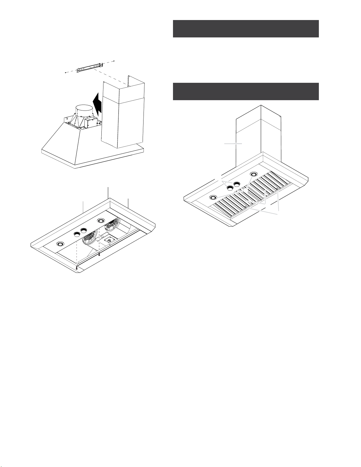
Install duct covers
• When using both upper and lower vent covers, push lower
cover down onto hood and lift upper cover to ceiling and
install with two mounting screws.
NOTE: For vented installations, the upper vent cover may be
reversed to hide slots.
• Secure the bottom of the duct with 2 - 4 x 8 mm screws.
Complete installation
• Install metal filters. See the “Mainteinance” section.
To get the most ecient use from your new range hood, read
the “maintenance” section.
Keep your Use, Care, and installation Guide close to range
hood for easy reference.
Description of the hood
5
1
3
4
2
1. Blower and light controls
2. LED lamps
3. Grease filter
4. Grease filter handle
5. Duct covers

11
Control
The range hood is designed to remove smoke, cooking vapors
and odors from the cooktop area. For best results, start the
hood before cooking and allow it to operate several minutes
after the cooking is complete to clear all smoke and odors
from the kitchen.
The hood controls are located on the center side of the hood.
Recessing Knobs
• You can hide control knobs by depressing them until flush
with the hood body.
• Pressing the knobs again will lower the knobs, and enable
the user to operate the lights and blower.
Controls
A
B
A. Lamps knob
B. Blower knob
Operating the lamps
1. Turn the light switch to the “ON” position to turn the
range hood lights On.
2. Turn the light switch to the “OFF” position to turn the
range hood lights O.
Operating the blower
1. Turn the blower switch at “1” to turn the range hood on.
2. Turn the blower switch to the desired speed position.
3. Turn the blower switch to the “MAX” position to turn the
range hood on High.
4. Turn the blower switch to the “OFF” position to turn the
range hood blower O.
Auto On blower
The range hood is equipped with a sensor to automatically turn
on the blower when excessive heat is detected in the control
area. When the blower switch is in the “Off” position, this sensor
will turn the blower to high speed when necessary. When the
heat decreases, the blower will turn off. When the blower switch
is in the On position, the heat sensor is not active and the range
hood functions normally.
 Loading...