


Use, Care, and
Installation Guide
Guide d’utilisation, d’entretien et d’installation
Guía de instalación, uso y mantenimiento
|
|
|
READ AND SAVE THESE |
|
|
|
INSTRUCTIONS |
|
|
|
LISEZ CES |
|
|
|
INSTRUCTIONS ET |
|
|
|
CONSERVEZ-LES |
|
LEA Y CONSERVE |
||
Model: |
|
EPR628S1 |
|
|
|||
|
|
|
ESTAS INSTRUCCIONES |
|
|
|
|
|
|
|
LIB0136622 |
|
|
|
Printed in Mexico |
1

ENGLISH
Contents |
|
Important safety notice ................................................................................................................................................................................................ |
3 |
List of materials ............................................................................................................................................................................................................... |
4 |
Parts supplied ............................................................................................................................................................................................................. |
4 |
Parts not supplied ..................................................................................................................................................................................................... |
4 |
Dimensions and clearances ........................................................................................................................................................................................ |
5 |
Venting requirements ................................................................................................................................................................................................... |
5 |
Ducting options and examples ................................................................................................................................................................................. |
6 |
Electrical requirements ................................................................................................................................................................................................ |
6 |
Installation ......................................................................................................................................................................................................................... |
9 |
Complete the installation ....................................................................................................................................................................................... |
10 |
Description of the hood ............................................................................................................................................................................................... |
10 |
Control ................................................................................................................................................................................................................................ |
10 |
Maintenance ...................................................................................................................................................................................................................... |
11 |
Warranty ............................................................................................................................................................................................................................. |
12 |
APPROVED FOR RESIDENTIAL APPLIANCES
FOR RESIDENTIAL USE ONLY
READ AND SAVE THESE INSTRUCTIONS
PLEASE READ ENTIRE INSTRUCTIONS BEFORE PROCEEDING.
INSTALLATION MUST COMPLY WITH ALL LOCAL CODES.
IMPORTANT: Save these Instructions for the Local Electrical Inspector’s use.
INSTALLER: Please leave these Instructions with this unit for the owner.
OWNER: Please retain these instructions for future reference.
Safety Warning: Turn off power circuit at service panel and lock out panel, before wiring this appliance. Requirement: 120 V AC, 60 Hz. 15 or 20 A Branch Circuit.
2

I IMPORTANT SAFETY NOTICE
I CAUTION
FOR GENERAL VENTILATING USE ONLY. DO NOT USE TO EXHAUST HAZARDOUS OR EXPLOSIVE MATERIALS OR VAPOURS.
IWARNING
TO REDUCE THE RISK OF FIRE, ELECTRIC SHOCK, OR INJURY TO PERSONS, OBSERVE THE FOLLOWING:
A.Use this unit only in the manner intended by the manufacturer. If you have questions, contact the manufacturer.
B.Before servicing or cleaning the unit, switch power off at service panel and lock service panel disconnecting means to prevent power from being switched on accidentally.
When the service disconnecting means cannot be locked, securely fasten a prominent warning device, such as a tag, to the service panel.
C.Installation work and electrical wiring must be done by qualified person(s) in accordance with all applicable codes & standards, including fire-rated construction.
D.Sufficient air is needed for proper combustion and exhausting of gases through the flue (Chimney) of fuel burning equipment to prevent backdrafting.
Follow the heating equipment manufacturers guideline and safety standards such as those published by the national fire protection association (NFPA), the american society for heating, refrigeration and air conditioning engineers (ASHRAE), and the local code authorities.
E.When cutting or drilling into wall or ceiling, do not damage electrical wiring and other hidden utilities.
F.Ducted systems must always be vented to the outdoors.
I CAUTION
To reduce risk of fire and to properly exhaust air, be sure to duct air outside - do not vent exhaust air into spaces within walls, ceilings, attics, crawl spaces, or garages.
IWARNING
TO REDUCE THE RISK OF A RANGE TOP GREASE FIRE.
a)Never leave surface units unattended at high settings. Boilovers cause smoking and greasy spillovers that may ignite. Heat oils slowly on low or medium settings.
b)Always turn hood ON when cooking at high heat or when flambeing food (I.e. Crepes Suzette, Cherries Jubilee, Peppercorn Beef Flambe’).
c)Clean ventilating fans frequently. Grease should not be allowed to accumulate on fan or filter.
d)Use proper pan size. Always use cookware appropriate for the size of the surface element.
e)Suitable for use in household cooking area.
IWARNING
TO REDUCE THE RISK OF INJURY TO PERSONS, IN THE EVENT OF A RANGE TOP GREASE FIRE, OBSERVE THE FOLLOWING:a
a)SMOTHER FLAMES with a close-fitting lid, cookie sheet, or other metal tray, then turn off the gas burner or the electric element. BE CAREFUL TO PREVENT BURNS. If the flames do not go out immediately, EVACUATE AND CALL THE FIRE DEPARTMENT.
b)NEVER PICK UP A FLAMING PAN - you may be burned.
c)DO NOT USE WATER, including wet dishcloths or towels - a violent steam explosion will result.
d)Use an extinguisher ONLY if:
1)You know you have a class ABC extinguisher, and you already know how to operate it.
2)The fire is small and contained in the area where it started.
3)The fire department is being called.
4)You can fight the fire with your back to an exit.
e)Ducted fans must always be vented to the outdoor.
aBased on “Kitchen Fire Safety Tips” published by NFPA.
IWARNING
TO REDUCE THE RISK OF FIRE, USE ONLY METAL DUCT WORK.
Install this hood in accordance with all requirements specified.
IWARNING
To reduce the risk of fire or electric shock, do not use this hood with any external solid state speed control device.
OPERATION
Always leave safety grills and filters in place. Without these components, operating blowers could catch onto hair, fingers and loose clothing.
The manufacturer declines all responsibility in the event of failure to observe the instructions given here for installation, maintenance and suitable use of the product.
The manufacturer further declines all responsibility for injury due to negligence and the warranty of the unit automatically expires due to improper maintenance.
I CAUTION
Automatically Operated Device - To Reduce The Risk Of Injury Disconnect From Power Supply Before Servicing.
3

LIST OF MATERIALS
Removing the packaging.
I CAUTION
Remove carton carefully, Wear gloves to protect against sharp edges.
I WARNING
Remove the protective film covering the product before putting into operation.
Supplied Part |
Pieces |
|
1 |
Hood assembly and |
|
LED lamps already installed |
|
4.5x13 mm |
8 |
|
|
4.2x15 mm |
2 |
|
|
3.5x9.5 mm |
4 |
|
|
4.2x19 mm |
8 |
|
Parts no supplied
Tools/Materials required
•Level
•Drill
•1⁄8” (3.0 mm) drill bit
•Pencil
•Pliers
•Tape measure or ruler
•Caulking gun and weatherproof caulking compound
•Flat-blade screwdriver
•Phillips screwdriver
•Saber or keyhole saw
•Metal snips
•Vent clamps
Parts needed
• 6” (15.2 cm) round metal vent system
Optional accessories and consumable parts
KIT |
|
# Part |
|
|
30” (76.2 cm) |
|
36” (91.4 cm) |
|
|
||
|
|
|
|
Recirculating Kit |
KIT02770 |
||
|
|
|
|
Hood Liner |
KIT02773 |
|
KIT02774 |
|
|
|
|
Supplied Part |
Pieces |
2
Mounting brackets
2
Metal spacers (for use when cabinet depth is greater than 12”)
3.5x9.5 mm |
6 |
|
|
Torx #10 adapter |
1 |
|
|
|
8 |
Ø 6.4x18 mm washers |
|
|
8 |
Ø 6.4x18 mm washers |
|
Location requirements:
IMPORTANT: Observe all governing codes and ordinances. Have a qualified technician install the range hood. It is the installer’s responsibility to comply with installation clearances specified on the model/serial rating plate. The model/serial rating plate is located inside the liner behind the filter on the left wall of the range hood.
Range hood location should be away from strong draft areas, such as windows, doors, and strong heating vents.
Cabinet opening dimensions that are shown must be used. Given dimensions provide minimum clearance. Consult your cooktop/ range manufacturer installation instructions before making any cutouts.
Grounded electrical outlet is required. See “Electrical Requirements” section.
The range hood is factory set for vented installations through the roof or wall. For non-vented (recirculating) installations see “NonVented (recirculating) Installation Through the Soffit/Cabinet” in the “Prepare Location” section. Recirculation Kit Part is available from your dealer or an authorized parts distributor. All openings in ceiling and wall where range hood will be installed must be sealed.
For mobile home installations
The installation of this range hood must conform to the Manufactured Home Construction Safety Standards, Title 24 CFR, Part 328 (formerly the Federal Standard for Mobile Home Construction and Safety, title 24, HUD, Part 280) or when such standard is not applicable, the standard for Manufactured Home Installation 1982 (Manufactured Home Sites, Communities and Setups) ANSI A225.1/NFPA 501A, or latest edition, or with local codes.
†®TORX is a registered trademark of Saturn Fasteners, Inc.
4
LOCATION REQUIREMENTS
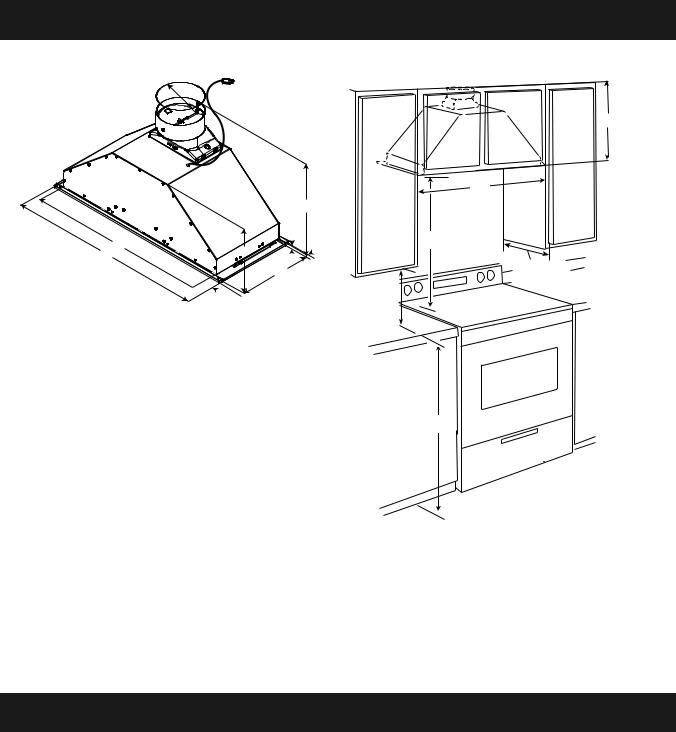
Product dimensions
B
A
I* - Metallic spacers Spacers has to be installed and used when cabinet depth is greater than 12”.
H
G
F
E
I*
D

 C
C
 I*
I*
|
Model |
|
|
|
EPR628S1 |
|
|
A |
2817⁄64” (71.8 cm) |
|
|
B |
26” (66 cm) |
|
|
C |
19⁄64” (2.9 cm) |
|
|
D |
10¾” (27.3 cm) |
|
|
E |
917⁄32” (24.2 cm) |
|
|
F |
021⁄64” (.85 cm) |
|
|
G |
149⁄16” (37 cm) |
|
|
H |
6” (15.2 cm) |
|
|
I* |
½” (1.27 cm) |
|
|
For gas range installation: Mount this hood so that the bottom edge is at minimum 27”(68,5 cm) above the cooking surface. For electric range installation: mount this hood so that the bottom is not less than 24”(61 cm).
Installation clearances
A
B
C
D
E
F
A. |
12” (30.5 cm) min. upper |
D. |
12” (30.48 cm) cabinet opening |
|
|
cabinet height |
|
depth* |
|
B. |
30” (76.2 cm) cabinet |
E. |
15” (38.1 cm) min. clearance |
|
|
upper cabinet to countertop |
|||
|
opening width* |
|
||
|
F. |
36” (91.4 cm) base cabinet |
||
C. |
24” (61 cm) min. 36” (91.4 cm) |
|||
|
height |
|||
|
suggested max. bottom of |
|
||
|
|
|
||
|
cabinet to cooking surface |
|
|
*NOTE: This range hood is set to 30” (76.2 cm) cabinet width x 12” (30.5 cm) deep cabinets.
Venting requirements
•Vent system must terminate to the outdoors, except for no vented (recirculating) installations.
•Do not terminate the vent system in an attic or other enclosed area.
•Do not use a 4” (10.2 cm) laundry-type wall cap.
•Rigid metal vent is recommended. Plastic or metal foil vent is not recommended. The length of vent system and number of elbows should be kept to a minimum to provide efficient performance.
For the most efficient and quiet operation:
•Use no more than three 90° elbows.
•Make sure there is a minimum of 24” (61 cm) of straight vent between the elbows if more than 1 elbow is used.
•Do not install 2 elbows together.
•Use clamps to seal all joints in the vent system.
•The vent system must have a damper.
•Use caulking to seal exterior wall or roof opening around the cap.
•The size of the vent should be uniform.
5
Cold weather installations
An additional back draft damper non return valve should be installed to minimize backward cold air flow and a thermal break should be installed to minimize conduction of outside temperatures as part of the vent system. The damper non return valve should be on the cold air side of the thermal break.
The break should be as close as possible to where the vent system enters the heated portion of the house.
Makeup air
Local building codes may require the use of makeup air systems when using ventilation systems with greater than specified CFM of air movement. The specified CFM varies from locale to locale.
Consult your HVAC professional for specific requirements in your area.
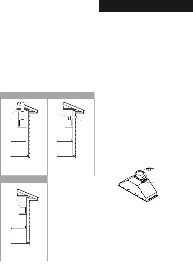
Venting methods
This range hood is factory set for venting through the roof or through the wall. You can apply the recirculating venting method by purchasing the Recirculation Kit.
The vent system needed for installation is not included. A 6” (15.2 cm) round vent system is recommended.
Roof venting |
Wall venting |
B
A
A.6” (15.2 cm) vent through the roof
B.Roof cap
Recirculating
A
B
A.6” (15.2 cm) vent through the wall
B.Wall cap
A
B 


A.6” (15.2 cm) vent through the cabinet
B.Round recirculating grid
Electrical requirements
I WARNING
PLUG INTO A GROUNDED 3 PRONG OUTLET. DO NOT REMOVE GROUND PRONG.
DO NOT USE AN ADAPTER.
DO NOT USE AN EXTENSION CORD.
FAILURE TO FOLLOW THESE INSTRUCTIONS CAN RESULT IN DEATH, FIRE, OR ELECTRICAL SHOCK.
IMPORTANT: The range hood must be electrically grounded in accordance with local codes and ordinances, or in the absence of local codes, with the National Electrical Code, ANSI/NFPA 70 (latest edition) or Canadian Electrical Code, CSA C22.1
No. 0-M91 (latest edition).
If codes permit and a separate ground wire is used, it is recommended that a qualified electrical installer determine that the ground path is adequate.
A copy of the above code standards can be obtained from:
National Fire Protection Association
1 Batterymarch Park
Quincy, MA 02169-7471
CSA International
8501 East Pleasant Valley Road
Cleveland, Ohio 44131-5575
•A 120 volt, 60 Hz, AC only, 15or 20-amp, fused electrical circuit is required. A time-delay fuse or circuit breaker is also recommended. It is recommended that a separate circuit serving only this range hood be provided.
•This range hood is equipped with a power supply cord having a 3 prong grounding plug.
•To minimize possible shock hazard, the cord must be plugged into a mating, 3 prong, grounding-type outlet, grounded in accordance with local codes and ordinances. If a mating outlet is not available, it is the personal responsibility and obligation of the customer to have the properly grounded outlet installed by a qualified electrician.
•The grounded 3 prong outlet is to be located inside the cabinet above the range hood at a maximum distance of 337⁄16” (85.0 cm) from where the power cord exits the hood. The grounded 3 prong outlet must be accessible after installation of the range hood. See illustration:
3315⁄32 (85 cm)
GROUNDING INSTRUCTIONS
•This range hood must be grounded. In the event of an electrical short circuit, grounding reduces the risk of electric shock by providing an escape wire for the electric current.
•This range hood is equipped with a cord having a grounding wire with a grounding plug. The plug must be plugged into an outlet that is properly installed and grounded.
•Do not operate any fan with a damaged cord or plug. Discard fan or return to an authorized service facility for examination and/or repair.
WARNING: Improper grounding can result in a risk of electric shock. Consult a qualified electrician if the grounding instructions are not completely understood, or if doubt exists as to whether
the range hood is properly grounded.
Do not use an extension cord. If the power supply cord is too short, have a qualified electrician install an outlet near the range hood.
SAVE THESE INSTRUCTIONS
6

Installation instructions
Prepare location
It is recommended that the vent system be installed before the range hood is installed.
•Before making cutouts, make sure there is proper clearance within the ceiling or wall for vent fittings.
•Making the cutout to the bottom of the cabinet may be easier to do prior to mounting the cabinet to the wall.
1Disconnect power.
2Determine which venting method to use: roof, wall, or non vented.
3Select a flat surface for assembling the range hood. Place covering over that surface.
I WARNING
EXCESSIVE WEIGHT HAZARD
USE TWO OR MORE PEOPLE TO MOVE AND INSTALL RANGE HOOD.
FAILURE TO DO SO CAN RESULT IN BACK OR OTHER INJURY.
4Using 2 or more people, lift range hood onto covered surface.
Range hood cabinet cutout
1Use a saber saw or keyhole saw to cut out the cabinet bottom inside the cabinet frame.
NOTE: Frameless type cabinets require ¾” (1.9 cm) front lip in the cabinet bottom. A¾”(1.9 cm) thick filler strip (not supplied) may be required for some types of cabinets. (See Step 3 in the “Install Range Hood” section).
Cut out dimensions (without spacers)
C A
B*
 G*
G*


 F
F
E
A
D
|
A. |
Cutout |
|
B. |
817⁄64” (21 cm) x 61⁄4” (15.9 cm)* |
|
C. |
7¾” (19.7 cm) centerline to cabinet front |
|
D. |
Centerline of the cabinet |
|
E. |
42⁄5” (10.6 cm) |
|
F. |
49⁄10” (12.5 cm) center to cabinet front |
|
G. |
Ø (6 cm)* |
|
|
|
Cabinet Height |
Hole Shape and Size |
|
|
|
|
15” (38.1 cm) |
A 61⁄4” (15.9 cm) diameter round opening is |
|
|
required. |
|
3⁄4” |
C |
A |
(1.9 cm) |
|
|
|
|
|
|
|
B* |
1⁄2” |
|
G* |
|
|
|
(1.27 cm) |
|
F |
|
|
|
107⁄8” |
|
E |
(27.62cm) |
|
A |
|
261⁄8” |
|
D |
|
|
|
|
|
|
|
|
|
(66.3 cm) |
|
|
|
|
|
A. Bottom of cabinet cutout |
|
|
|
|
2 Complete cabinet preparation following the instructions |
|
|
|
|
|
for your type of venting. Determine venting cutout loca- |
|
A. |
Cutout |
||
tions and cut out vent openings in the cabinets, walls and/ |
|
||||
|
B. |
Ø 6¼” (15.9 cm)* |
|||
or soffit. |
|
|
C. |
71⁄2” (19 cm) centerline to cabinet front |
|
Venting outside through the roof |
|
D. Centerline of the cabinet |
|||
|
E. |
42⁄5” (10.6 cm) |
|||
1 Measure and mark the lines as shown. Use a saber saw or |
|
F. |
49⁄10” (12.5 cm) center to cabinet front |
||
|
G. |
Ø (6 cm)* |
|||
keyhole saw to cut an opening through the top of the cabinet |
|
||||
|
|
|
|
||
and the roof for the vent. |
1 Install the 6” (15.2 cm) vent transition to the top of the |
||||
|
|
||||
|
|
|
range hood liner (if removed for shipping) using two |
||
|
Cutout Chart |
|
|||
|
|
3.5 x 9.5 mm screws. Assemble the vent duct that you |
|||
Cabinet Height |
Hole Shape and Size |
|
will use over the 6” (15.2 cm) vent transition. |
||
|
|
|
|
||
|
|
|
|
|
|
12” (30.5 cm) |
A 817⁄64” wide x 6¼” deep (21 cm x 15.9 cm) |
|
|
|
|
|
rectangular opening in the cabinet top is |
|
|
|
|
|
required for damper transition clearance. |
|
|
|
|
7

Venting outside through the wall
1Measure from the bottom of the range hood liner to the horizontal centerline of the vent opening (A).
B |
A |
C |
D |
A.Measurement A
B.Horizontal centerline of vent opening
C.Range hood liner
D.12” (30.5 cm) min. cabinet height
5Remove the vent duct from the range hood liner. Transfer measurement A to the cabinet back wall. Measure from the underside of the cabinet.
6Mark the cutout as shown. Use a saber saw or keyhole saw to cut a round opening through the back of the cabinet and the exterior wall for the vent.
|
C |
|
|
A. |
Measurement A |
|
B. |
Centerline |
A |
C. |
6¼” (15.9 cm) |
|
round cutout |
|
|
|
B
Non-vented (recirculating) installation through the soffit/ cabinet
|
A |
G |
G |
|
|
|
B |
D |
F |
|
|
F |
I |
|
E |
|
H |
A.Ceiling
B.Vent cover
C.Soffit
D.6” (15.2 cm) vent
E.Range hood
|
A |
|
B |
|
C |
|
D |
|
E |
F. |
Cabinet |
G. |
Wall |
H.12” (30.5 cm) min. cabinet height
I.17” (43.2 cm) min. vent cover height
1Measure and mark the centerline of the cabinet to the soffit above.
2Measure from the bottom of the cabinet to the centerline of the where the vent will come through the soffit. Mark the location and use a saber saw or keyhole saw to cut a 5¾” (14.6 cm) hole for the vent cover.
A
B
A. Vent cover
B. Centerline
*NOTE: For 12” (30.5 cm) high cabinets a 6¼” deep x 8” wide (14.6 cm x 20.3 cm) rectangular opening in the cabinet top is required for damper transition clearance.
3Consider the cutout chart measures to make the openings on the cabinet.
Complete preparation
1If not yet attached, install the 6” (15.2 cm) vent transition the top of the range hood liner using two 3.5 x 9.5 mm screws.
2Locate side mounting bracket flush 1 cm to the bottom of the cabinet side and against the inside of the front cabinet face. Orient the bracket depending on the width of your cabinet as depicted in the diagrams below. Drill 1⁄8” (3 mm) pilot holes in 6 places, attach a bracket using three 4.5
x 13 mm screws to each side of the cabinet, and tighten. Additional washers in hardware package are supplied as spacers for cabinet walls thinner than ½”(13 mm).
Bracket Orientation for 30” (76.2 cm) Cabinet
B
A
C
D
A.30” (76.2 cm) cabinet
B.Screws - 4.5 x 13 mm (8)
C.Washers (optional)
D.Mounting bracket (2) (position for 30” [76.2 cm] cabinet)
8

Bracket Orientation for 30” (76.2 cm) Cabinet
C
A
B
D
A.30” (76.2 cm) cabinet
B.Screws - 4.5 x 13 mm (8)
C.Washers (optional)
D.Mounting bracket (2) (position for 30” [76.2 cm cabinet)
Move the bracket 6⁄16” (1 cm) from the bottom side of the cabinet
5Install the vent system according to the method needed. Use caulking to seal the exterior wall or roof opening.
Install range hood
I WARNING
EXCESSIVE WEIGHT HAZARD.
USE TWO OR MORE PEOPLE TO MOVE AND INSTALL RANGE HOOD.FAILURE TO DO SO CAN RESULT IN BACK OR OTHER INJURY.
1Using 2 or more people, lift the hood liner into its mounted location. Attach with four 4.2 x 19 mm screws into the slotted openings. Do not tighten screws.
2Center the canopy in the cabinet. Align the bottom of the canopy with the bottom of the cabinet. Install four 4.2 x 19 mm screws into the hood canopy assembly and tighten all (8) mounting screws.
5 Attach the face plate to the hood insert. Tighten to secure. NOTE: If cabinet depth is greater than 12”, it is recommended that the two 1⁄2” metal spacers are installed.
Install to front and rear sides of the face plate with 3.5 x 9.5 mm screws as shown in drawing.
A |
|
B |
C |
A. Cabinet |
C. Screws - 4.2 x 19 mm (8) |
B.Hood liner canopy assembly
3Remove the metal grease filters from the face panel.
4Connect the lamps connector to the connector present inside the hood as shown in drawing.
A
B
A.Lamp connector
B.Hood connector
A. Face Panel |
C. Screws - 3.5 x 9.5 mm (4) |
B.Front and rear spacer
B
C
 D
D
A
A.Screws - 3.5 x 9.5 mm flat-head (4)
B.Face plate (30” x 12”[76.2 cm x 30.5 cm] shown)
C.Cabinet (30” x 12” [76.2 cm x 30.5 cm] shown)
D.Screws - 4.2 x 15 mm truss-head (2)
9
Connect the vent system |
|
Description of the hood |
|
|
|
Vented Installations
1Connect the vent system to the range hood vent opening. Seal the connection with clamps.
Non-Vented (recirculating) Installations
1Connect the vent system to the range hood vent opening. Seal the connection with clamps.
2Install charcoal filters.
See the “Available accesories” section.
The range hood is designed to remove smoke, cooking vapors and odors from the cooktop area. For best results, start the hood before cooking and allow it to operate several minutes after the cooking is complete to clear all smoke and odors from the kitchen.
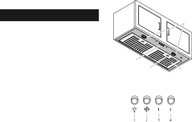
The hood controls are located on the center of the front of the range hood liner.
Complete installation
1 Replace grease filters. See the “Maintenance” section.
I WARNING
ELECTRICAL SHOCK HAZARD
I WARNING
PLUG INTO A GROUNDED 3 PRONG OUTLET. DO NOT REMOVE GROUND PRONG.
DO NOT USE AN ADAPTER.
DO NOT USE AN EXTENSION CORD.
FAILURE TO FOLLOW THESE INSTRUCTIONS CAN RESULT IN DEATH, FIRE, OR ELECTRICAL SHOCK.
2Plug 3-prong power cord into a grounded 3-prong outlet located inside the cabinet above the range hood.
3Check the operation of the range hood fan and light.
See “Description of the hood” section. If range hood does
not operate, check to see whether a circuit breaker has Controls tripped or a household fuse has blown. Disconnect power
and check wiring connections.
NOTE: To get the most efficient use from your new range hood, read the “Description of the hood” section.
A
B
A.Blower and light controls
B.Grease filter handle
C.Grease filter
D.LED lamps
1.On/Off light button
2.Blower off and speed minimum button
3.Blower speed medium button
4.Blower speed maximum button
D
C
Operating the Light
The On/Off light button controls all lights. Press once for On and again for Off.
Operating the Blower
The BLOWER SPEED buttons turn the blower on and control the blower speed and sound level for quiet operation.
The speed can be changed anytime during fan operation by pressing the desired blower speed button.
Press the BLOWER OFF button a second time to turn off the blower.
10
Maintenance |
|
Available accessories |
|
|
|
Cleaning
Do not spray cleaners directly to the control while cleaning the Hood. The cooker hood should be cleaned regularly (at least with the same frequency with which you carry out maintenance of the fat filters) internally and externally. Clean using the cloth dampened with neutral liquid detergent. Do not use abrasive products.
DO NOT USE ALCOHOL!
IWARNING:
Failure to carry out the basic cleaning recommendations of the cooker hood and replacement of the filters may cause fire risks. Therefore, we recommend oserving these instructions.
The manufacturer declines all responsibility for any damage to the motor or any fire damage linked to inappropriate maintenance or failure to observe the above safety recommendations.
Metal grease filter
The filters should be washed frequently. Place metal filters in dishwasher or hot detergent solution to clean. Let filter dry thoroughly before replacing it.
Turn off fan and lights. Allow lamps to cool.
1Remove each filter by pushing down the spring release handle and then pulling down the filter.
2Wash metal filters as needed in dishwasher or hot detergent solution.
3Reinstall the filter by making sure the spring release handles are toward the front. Insert metal grease filter into upper track.
4Pull the spring release handle down.
5Push up on metal filter and release handle to latch into place.
6Repeat steps 1-5 for the other filter.
Replacing a LED lamp
The LED lights are replaceable by a service technician only. See “Who to contact” section in the warranty for service contact information.
Recirculating kit
If it is not possible to vent cooking fumes and vapors to the outside, the range hood can be used in the non-vented (recirculating) version, using a charcoal filter. Recirculation Kit is available from the dealer or an authorized parts distributor.
|
A |
G |
G |
|
|
|
B |
D |
F |
|
|
F |
I |
|
|
|
E |
|
H |
A |
B |
C |
D |
E |
A. |
Ceiling |
F. |
Cabinet |
|
B. |
Vent cover |
G. |
Wall |
|
C. |
Soffit |
H. |
12” |
(30.5 cm) min. cabinet height |
D. |
6” (15.2 cm) vent |
I. |
17” |
(43.2 cm) min. vent cover height |
E.Range hood
NOTE: 12” (30.5 cm) high cabinets without a soffit may allow the 6” vent and vent cover to be seen.
1Cover the grill that protects the suction motor with the carbon filter so that the slots on the filter correspond to the pins on the sides of the motor protection grill.
2Turn the carbon filter clockwise to block them (bayonet
fixing).
•The charcoal filters cannot be cleaned. It should be replaced every 4-6 months (depending on hood usage).
•Remove the cable ties in the carbon filter to be able to turning it clockwise.
Extension liner kit
•30” wide x 17” or 20” deep liner provides complete protection of the cabinets.
•36” wide x 17” or 20” deep liner provides complete protection of the cabinets.
See Liner installation instructions for more detail.
11
 Loading...