

Page 1
BT-SM 2131 Dual
Sliding Mitre Saw
Artikel-Nr.: 4300830
Ident-Nr.: 11010
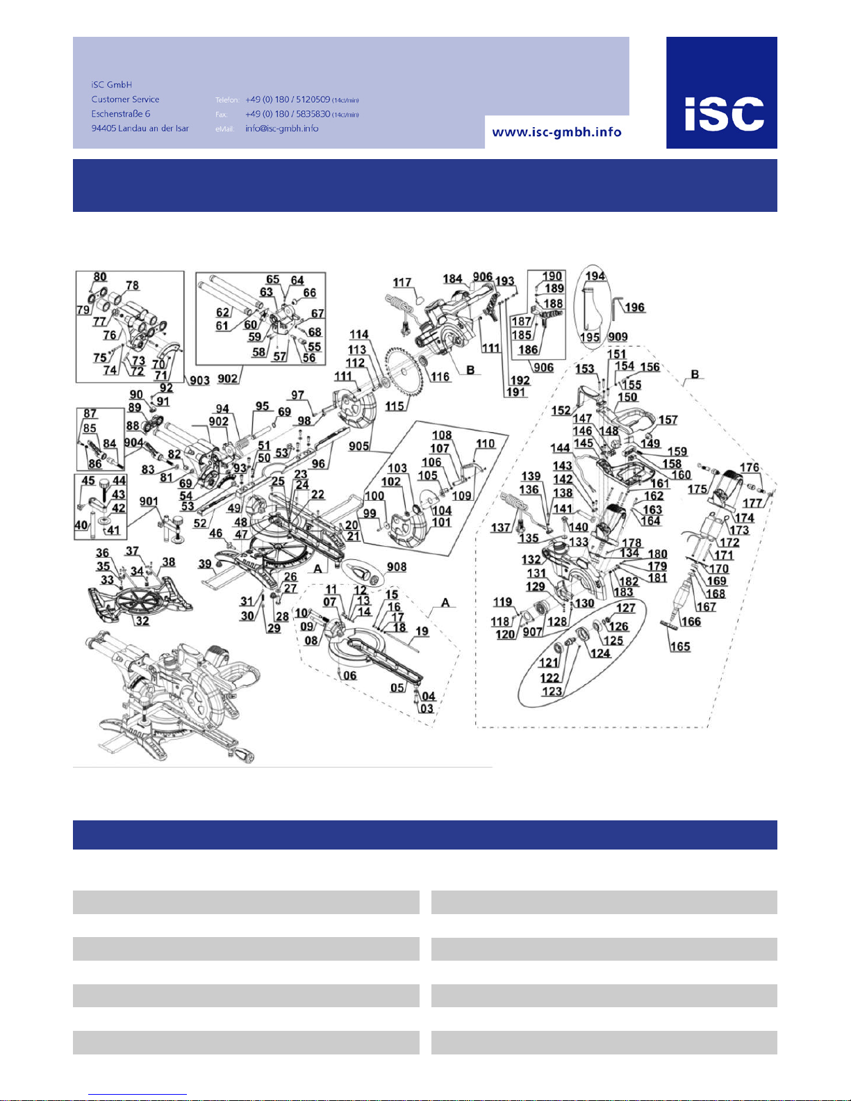
Komponenten / Ersatzteile
Position Artikel-Nr. Beschreibung
Position Artikel-Nr. Beschreibung
3 430083001003 hex bolt M10x30
4 430083001004 hex thin nutM10
20 430083001020 cross panhead screw M4x10 für Tischeinlage M4x10
21 430083001021 kerf board
22 430083001022 turnplate pointer
23 430083001023 cross panhead screw M5x16
24 430083001024 spring washer5
25 430083001025 flat washer5
38 430083001038 back bearing pole
39 430083001039 supporting pole
46 430083001046 locking screw für Werkstückauflage
49 430083001049 support
50 430083001050 flat washer6
51 430083001051 lnner hex screw M6x16
52 430083001052 support left panel links
53 430083001053 locking screwM6x85
Page 2

Komponenten / Ersatzteile
Position Artikel-Nr. Beschreibung
Position Artikel-Nr. Beschreibung
96 430083001096 support right panel rechts
112 430083001112 lnner hex screw M8x16-L linksgewinde M8x16
113 430083001113 big flat washer8
114 430083001114 outside board of saw balde
116 430083001116 inner board of saw blade
136 430083001136 cable wire clamp
137 430083001137 power cord
140 430083001140 clamping knodM6x55 für Schnitttiefenbegrenzung
145 430083001145 below handle
148 430083001148 transformer
149 430083001149 capacitor0.33uF
150 430083001150 top handle
151 430083001151 self-tapping screw st4.8x32
152 430083001152 handle
153 430083001153 self-tapping screw st4.8x38
157 430083001157 switch
158 430083001158 switch button
159 430083001159 bless spring of switch button
160 430083001160 microswitch
172 430083001172 stator
174 430083001174 housing
175 430083001175 brush holder(pair)
176 430083001176 carbon brush(pair)
177 430083001177 brush holder end cap
196 430083001196 cage spanner 6mm
901 430083001901 workpiece clip assy.
902 430083001902 pulling pole assy.
903 430083001903 rocking arm assy.
904 430083001904 rocking arm spanner assy.
905 430083001905 active cover link assy.
906 430083001906 self-lock button assy.
907 430083001907 gear box assy.
908 430083001908 locking handle assy.
909 430083001909 dust bag assy.
0 430083001197 front foot left
0 430083001198 back foot right
0 430083001199 back foot left
0 430083001200 front foot right
0 430083001201 screw for foot für Standfuss
0 430083001202 Screw for foot für Standfuss
0 430083001203 washer for foot für Standfuss
0 430083001204 spring washer for foot
0 430083001205 cage spanner 5mm
Page 3
Art.-Nr.: 43.008.30 I.-Nr.: 11010
k
Originalbetriebsanleitung
Zug-, Kapp- und Gehrungssäge
t
Original operating instructions
Drag, Crosscut and Miter Saw
p
Mode d’emploi d’origine
Scie à onglet radiale
C
Istruzioni per l’uso originali
Sega a trazione per troncature e tagli obliqui
U
Original-bruksanvisning
Drag-, kap- och geringssåg
j
Originální návod k obsluze
Kapovací a pokosová pila s pojezdem
W
Originálny návod na obsluhu
Tesárska, kapovacia a pokosová píla
N
Originele handleiding
Trek-, afkort- en verstekzaag
m
Manual de instrucciones original
Sierra de tracción, oscilante y para cortar
ingletes
O
Manual de instruções original
Serra de tracção, corte transversal e
meia-esquadria
q
Alkuperäiskäyttöohje
Veto-, katkaisu- ja jiirisaha
z
Πρωτότυπες Οδηγίες χρήσης
Φαλτσοπρίονο και πριόνι κάθετης κοπής
Z
Orijinal Kullanma Talimatı
Gönye Kesme
BT-SM
2131 Dual
Anleitung_BT_SM_2131_Dual_SPK7:_ 14.10.2010 15:37 Uhr Seite 1
Page 4
1
22
38
1
3
9b
34
8
19
6
7
18
9d
2 3
2
34
11
10
35
21
6
7
28
5
17
15
12
16
9a
1810
14
13
13
26
21
14
33
20
37 2
4
27
25
23
24
24
12
23 z
8
g (8x)
h (4x)
i (12x)
j (12x)
9a
9b
9c
9d
10
d
c
Anleitung_BT_SM_2131_Dual_SPK7:_ 14.10.2010 15:38 Uhr Seite 2
Page 5
3
4a 4b
26
10
g
j
h
j
i
6 7a
21
30
4c 5
30
29
21
9b
9d
i
h
j
i
36
g
j
i
Anleitung_BT_SM_2131_Dual_SPK7:_ 14.10.2010 15:38 Uhr Seite 3
Page 6
4
7b
30
8
17
19
a
20
19
20
7
9
20
b
19
10
34
c
11
12a
7
Anleitung_BT_SM_2131_Dual_SPK7:_ 14.10.2010 15:39 Uhr Seite 4
Page 7
5
12b
34
13a
13b
14a
14b
15
34
27
34
34
34
Anleitung_BT_SM_2131_Dual_SPK7:_ 14.10.2010 15:39 Uhr Seite 5
Page 8
6
16
17
5
18
z
c
f
31
32
d
Anleitung_BT_SM_2131_Dual_SPK7:_ 14.10.2010 15:39 Uhr Seite 6
Page 9

7
D
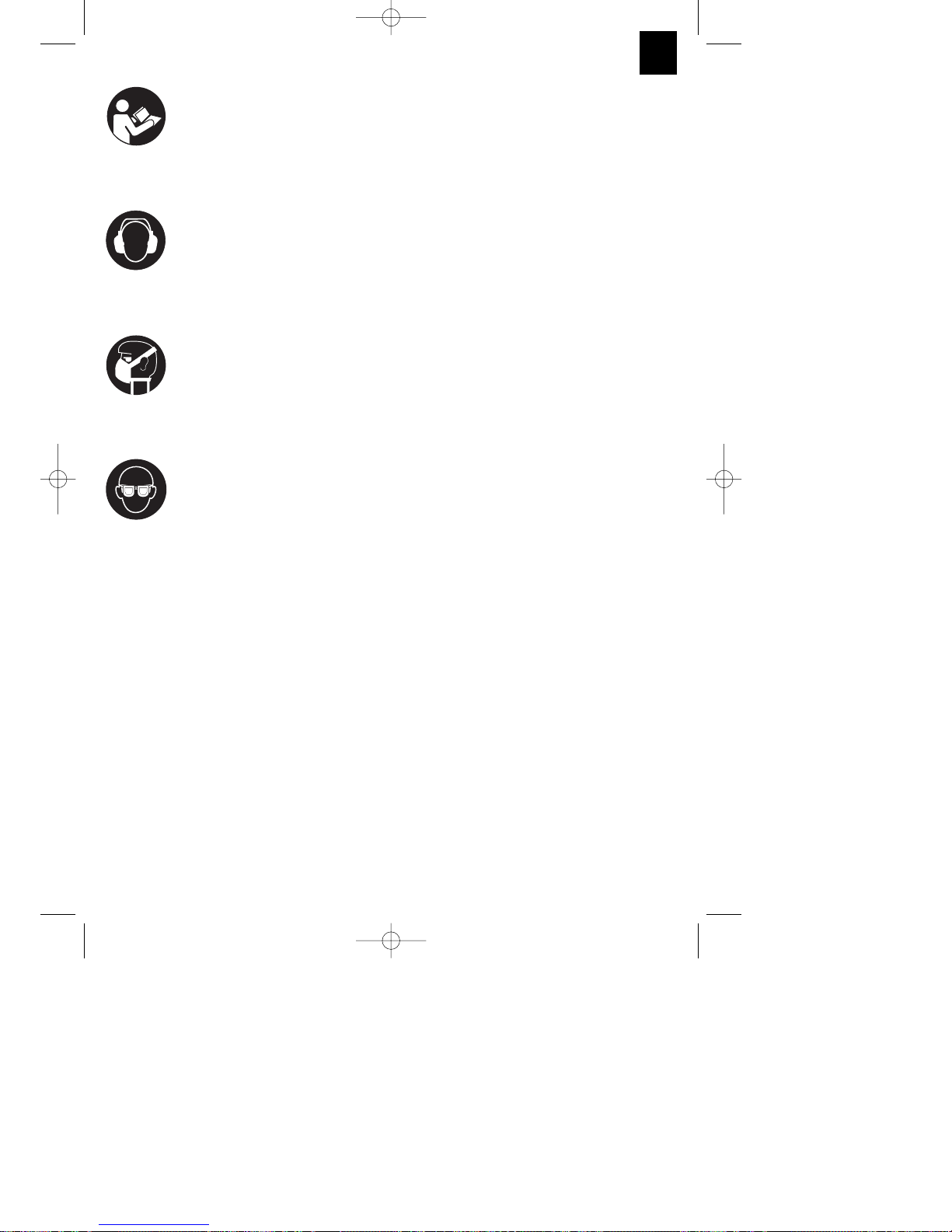
“WARNUNG - Zur Verringerung des Verletzungsrisikos Bedienungsanleitung lesen”.
Tragen Sie einen Gehörschutz.
Die Einwirkung von Lärm kann Gehörverlust bewirken.
Tragen Sie eine Staubschutzmaske.
Beim Bearbeiten von Holz und anderer Materialien kann gesundheitsschädlicher Staub
entstehen. Asbesthaltiges Material darf nicht bearbeitet werden!
Tragen Sie eine Schutzbrille.
Während der Arbeit entstehende Funken oder aus dem Gerät heraustretende Splitter, Späne
und Stäube können Sichtverlust bewirken.
Anleitung_BT_SM_2131_Dual_SPK7:_ 14.10.2010 15:39 Uhr Seite 7
Page 10

8
D
Inhaltsverzeichnis:
1. Sicherheitshinweise
2. Gerätebeschreibung
3. Lieferumfang
4. Bestimmungsgemäße Verwendung
5. Technische Daten
6. Vor Inbetriebnahme
7. Betrieb
8. Austausch der Netzanschlussleitung
9. Reinigung, Wartung und Ersatzteilbestellung
10. Lagerung
11. Entsorgung und Wiederverwertung
Anleitung_BT_SM_2131_Dual_SPK7:_ 14.10.2010 15:39 Uhr Seite 8
Page 11
Achtung!
Beim Benutzen von Geräten müssen einige
Sicherheitsvorkehrungen eingehalten werden, um
Verletzungen und Schäden zu verhindern. Lesen Sie
diese Bedienungsanleitung / Sicherheitshinweise
deshalb sorgfältig durch. Bewahren Sie diese gut
auf, damit Ihnen die Informationen jederzeit zur
Verfügung stehen. Falls Sie das Gerät an andere
Personen übergeben sollten, händigen Sie diese
Bedienungsanleitung / Sicherheitshinweise bitte mit
aus. Wir übernehmen keine Haftung für Unfälle oder
Schäden, die durch Nichtbeachten dieser Anleitung
und den Sicherheitshinweisen entstehen.
1. Sicherheitshinweise
Die entsprechenden Sicherheitshinweise finden Sie
im beiliegenden Heftchen!
WARNUNG
Lesen Sie alle Sicherheitshinweise und
Anweisungen. Versäumnisse bei der Einhaltung der
Sicherheitshinweise und Anweisungen können
elektrischen Schlag, Brand und/oder schwere
Verletzungen verursachen.
Bewahren Sie alle Sicherheitshinweise und
Anweisungen für die Zukunft auf.
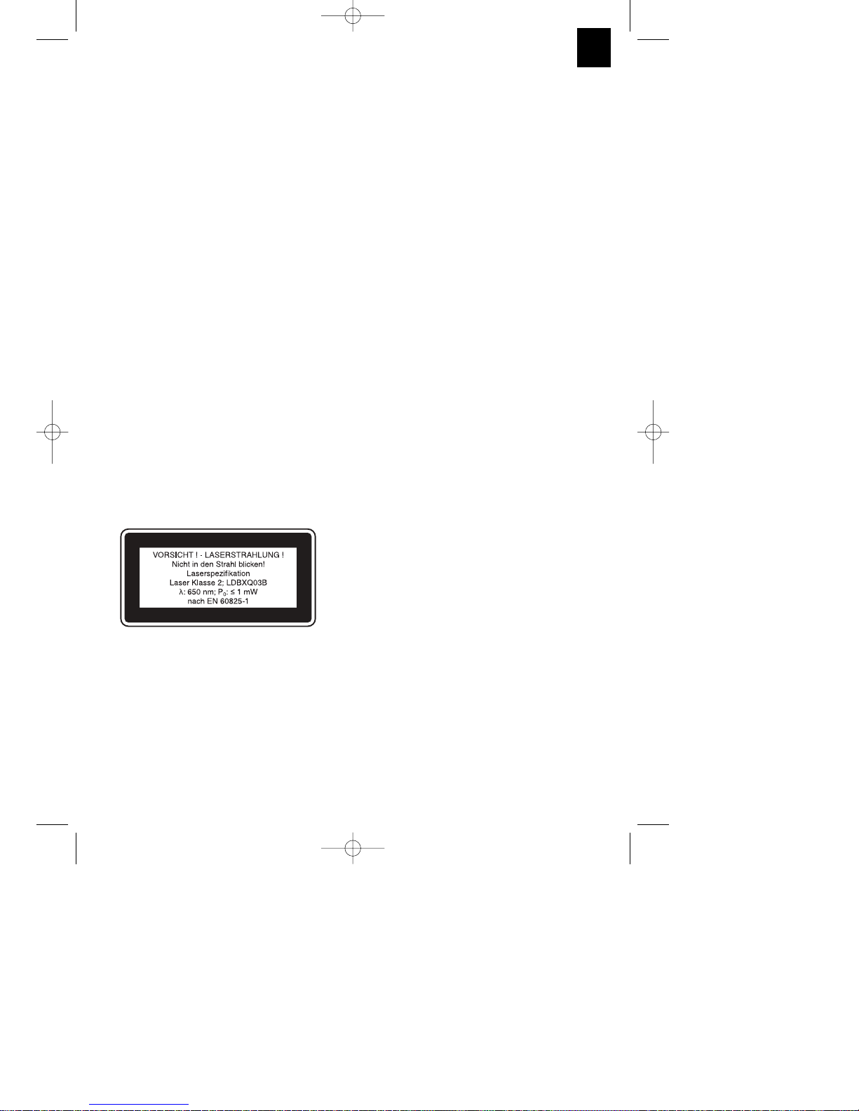
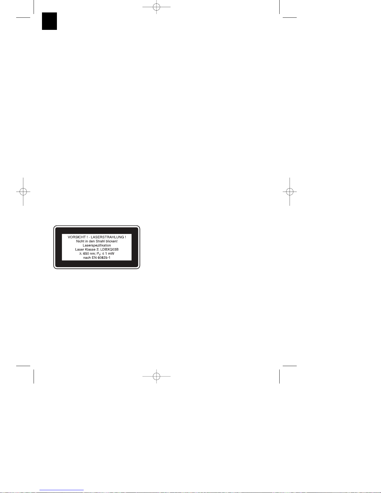
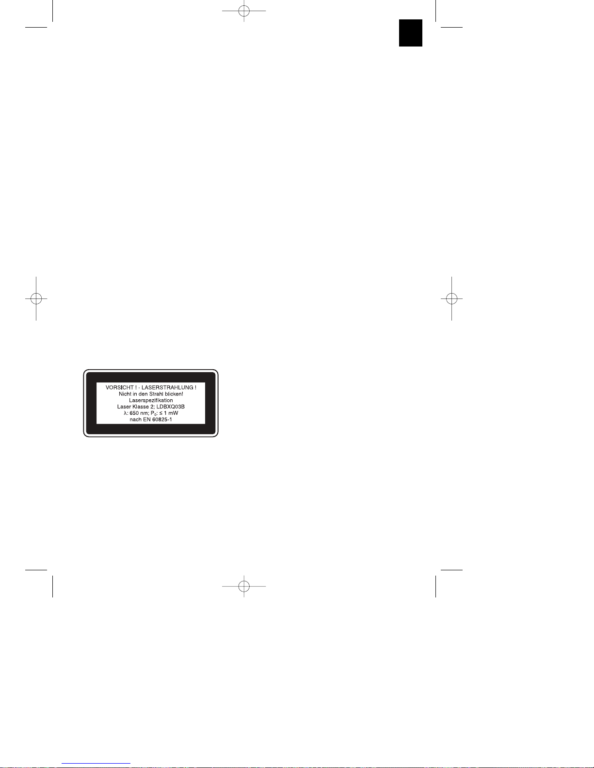
1.1 Spezielle Hinweise zum Laser
Achtung: Laserstrahlung
Nicht in den Strahl blicken
Laserklasse 2
Niemals direkt in den Strahlengang blicken.
Den Laserstrahl nie auf reflektierende Flächen
und Personen oder Tiere richten. Auch ein
Laserstrahl mit geringer Leistung kann Schäden
am Auge verursachen.
Vorsicht - wenn andere als die hier angegebenen
Verfahrensweisen ausgeführt werden, kann dies
zu einer gefährlichen Strahlungsexposition
führen.
Lasermodul niemals öffnen.
Wenn die Kappsäge längere Zeit nicht benutzt
wird, sollten die Batterien entfernt werden.
Es ist nicht erlaubt Veränderungen am Laser
vorzunehmen um die Leistung des Lasers zu
erhöhen.
Der Hersteller übernimmt keine Haftung für
Schäden die durch Nichtbeachtung der
Sicherheitshinweise entstehen.
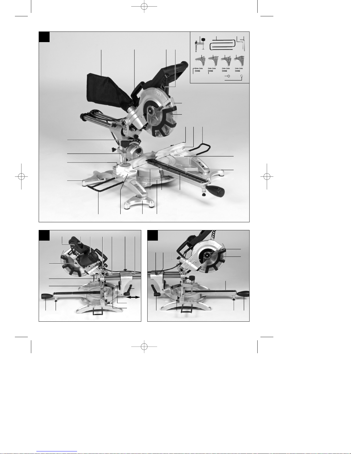
2. Gerätebeschreibung
1. Handgriff
2. Ein-/Ausschalter
3. Entriegelungshebel
4. Maschinenkopf
5. Sägewellensperre
6. Sägeblattschutz beweglich
7. Sägeblatt
8. Spannvorrichtung
9. zusätzliche Standfüße
10. Werkstückauflage
11. feststehende Anschlagschiene
12. Tischeinlage
13. verstellbarer Standfuss
14. Feststellschraube
15. Zeiger
16. Skala
17. Drehtisch
18. feststehender Sägetisch
19. Skala
20. Zeiger
21. Feststellschraube
22. Spänefangsack
23. Zugführung
24. Feststellschraube für Zugführung
25. Sicherungsbolzen
26. Feststellschraube für Werkstückauflage
27. Rändelschraube für Schnitttiefenbegrenzung
28. Anschlag für Schnitttiefenbegrenzung
29. Justierschraube
30. Justierschraube
31. Flanschschraube
32. Außenflansch
33. Knopf
34. bewegliche Anschlagschiene
35. Laser
36. ausklappbarer Standbügel
37. Ein / Ausschalter Laser
38. Transportgriff
9
D
Anleitung_BT_SM_2131_Dual_SPK7:_ 14.10.2010 15:39 Uhr Seite 9
Page 12

D
10
3. Lieferumfang (Bild 1-3)
Öffnen Sie die Verpackung und nehmen Sie das
Gerät vorsichtig aus der Verpackung.
Entfernen Sie das Verpackungsmaterial sowie
Verpackungs-/ und Transportsicherungen (falls
vorhanden).
Überprüfen Sie, ob der Lieferumfang vollständig
ist.
Kontrollieren Sie das Gerät und die Zubehörteile
auf Transportschäden.
Bewahren Sie die Verpackung nach Möglichkeit
bis zum Ablauf der Garantiezeit auf.
ACHTUNG
Gerät und Verpackungsmaterial sind kein
Kinderspielzeug! Kinder dürfen nicht mit
Kunststoffbeuteln, Folien und Kleinteilen spielen!
Es besteht Verschluckungs- und
Erstickungsgefahr!
Zug-, Kapp und Gehrungssäge
Spannvorrichtung (8)
2 x Werkstückauflage (10)
Spänefangsack (22)
Inbusschlüssel (c,d)
zusätzliche Standfüße (9)
Originalbetriebsanleitung
Sicherheitshinweise
4. Bestimmungsgemäße Verwendung
Die Zug-, Kapp- und Gehrungssäge dient zum
Kappen von Holz und Kunststoff, entsprechend der
Maschinengröße. Die Säge ist nicht zum Schneiden
von Brennholz geeignet.
Die Maschine darf nur nach ihrer Bestimmung
verwendet werden. Jede weitere darüber hinausgehende Verwendung ist nicht bestimmungsgemäß.
Für daraus hervorgerufene Schäden oder
Verletzungen aller Art haftet der Benutzer/Bediener
und nicht der Hersteller.
Bitte beachten Sie, dass unsere Geräte
bestimmungsgemäß nicht für den gewerblichen,
handwerklichen oder industriellen Einsatz konstruiert
wurden. Wir übernehmen keine Gewährleistung,
wenn das Gerät in Gewerbe-, Handwerks- oder
Industriebetrieben sowie bei gleichzusetzenden
Tätigkeiten eingesetzt wird.
Es dürfen nur für die Maschine geeignete Sägeblätter
verwendet werden. Die Verwendung von
Trennscheiben aller Art ist untersagt.
Bestandteil der bestimmungsgemäßen Verwendung
ist auch die Beachtung der Sicherheitshinweise,
sowie die Montageanleitung und Betriebshinweise in
der Bedienungsanleitung.
Personen, die die Maschine bedienen und warten,
müssen mit dieser vertraut und über mögliche
Gefahren unterrichtet sein. Darüber hinaus sind die
geltenden Unfallverhütungsvorschriften genauestens
einzuhalten. Sonstige allgemeine Regeln in
arbeitsmedizinischen und sicherheitstechnischen
Bereichen sind zu beachten.
Veränderungen an der Maschine schließen eine
Haftung des Herstellers und daraus entstehende
Schäden gänzlich aus. Trotz bestimmungsgemäßer
Verwendung können bestimmte Restrisikofaktoren
nicht vollständig ausgeräumt werden. Bedingt durch
Konstruktion und Aufbau der Maschine können
folgende Punkte auftreten:
Berührung des Sägeblattes im nicht abgedeckten
Sägebereich.
Eingreifen in das laufende Sägeblatt
(Schnittverletzung)
Rückschlag von Werkstücken und
Werkstückteilen.
Sägeblattbrüche.
Herausschleudern von fehlerhaften
Hartmetallteilen des Sägeblattes.
Gehörschäden bei Nichtverwendung des nötigen
Gehörschutzes.
Gesundheitsschädliche Emissionen von
Holzstäuben bei Verwendung in geschlossenen
Räumen.
Anleitung_BT_SM_2131_Dual_SPK7:_ 14.10.2010 15:39 Uhr Seite 10
Page 13

D
11
5. Technische Daten
Wechselstrommotor: 230 V ~ 50Hz
Leistung: 1500 W S1 / 1800 W S2 5 min
Leerlaufdrehzahl n0: 5000 min
-1
Hartmetallsägeblatt: ø 210 x ø 30 x 2,8 mm
Anzahl der Zähne: 48
Schwenkbereich: -45° / 0°/ +45°
Gehrungsschnitt nach links: 0° bis 45°
Gehrungsschnitt nach rechts: 0° bis 45°
Sägebreite bei 90°: 310 x 62 mm
Sägebreite bei 45°: 210 x 62 mm
Sägebreite bei 2 x 45°
(Doppelgehrungsschnitt links): 210 x 36 mm
Sägebreite bei 2 x 45°
(Doppelgehrungsschnitt rechts): 210 x 20 mm
Gewicht: ca. 11 kg
Laserklasse: 2
Wellenlänge Laser: 650 nm
Leistung Laser: ≤ 1 mW
Die Einschaltdauer S2 5 min (Kurzzeitbetrieb) sagt
aus, dass der Motor mit der Nennleistung (1800 W)
nur für die auf dem Datenschild angegebene Zeit (5
min) dauernd belastet werden darf. Andernfalls
würde er sich unzulässig erwärmen. Während der
Pause kühlt sich der Motor wieder auf seine
Ausgangstemperatur ab.
Geräusch und Vibration
Die Geräusch- und Vibrationswerte wurden entsprechend EN 61029 ermittelt.
Schalldruckpegel L
pA
93 dB(A)
Unsicherheit K
pA
3 dB
Schallleistungspegel L
WA
104 dB(A)
Unsicherheit K
WA
3 dB
Tragen Sie einen Gehörschutz.
Die Einwirkung von Lärm kann Gehörverlust bewirken.
Schwingungsgesamtwerte (Vektorsumme dreier
Richtungen) ermittelt entsprechend EN 61029.
Schwingungsemissionswert a
h
= 2,44 m/s
2
Unsicherheit K = 1,5 m/s
2
Zusätzliche Informationen für Elektrowerkzeuge
Warnung!
Der angegebene Schwingungsemissionswert ist nach
einem genormten Prüfverfahren gemessen worden
und kann sich, abhängig von der Art und Weise, in
der das Elektrowerkzeug verwendet wird, ändern
und in Ausnahmefällen über dem angegebenen
Wert liegen.
Der angegebene Schwingungsemissionswert kann
zum Vergleich eines Elektrowerkzeuges mit einem
anderen verwendet werden.
Der angegebene Schwingungsemissionswert kann
auch zu einer einleitenden Einschätzung der
Beeinträchtigung verwendet werden.
Beschränken Sie die Geräuschentwicklung und
Vibration auf ein Minimum!
Verwenden Sie nur einwandfreie Geräte.
Warten und reinigen Sie das Gerät regelmäßig.
Passen Sie Ihre Arbeitsweise dem Gerät an.
Überlasten Sie das Gerät nicht.
Lassen Sie das Gerät gegebenenfalls
überprüfen.
Schalten Sie das Gerät aus, wenn es nicht
benutzt wird.
Restrisiken
Auch wenn Sie dieses Elektrowerkzeug
vorschriftsmäßig bedienen, bleiben immer
Restrisiken bestehen. Folgende Gefahren
können im Zusammenhang mit der Bauweise und
Ausführung dieses Elektrowerkzeuges auftreten:
1. Lungenschäden, falls keine geeignete
Staubschutzmaske getragen wird.
2. Gehörschäden, falls kein geeigneter Gehörschutz
getragen wird.
3. Gesundheitsschäden, die aus Hand-ArmSchwingungen resultieren, falls das Gerät über
einen längeren Zeitraum verwendet wird oder
nicht ordnungsgemäß geführt und gewartet wird.
Anleitung_BT_SM_2131_Dual_SPK7:_ 14.10.2010 15:39 Uhr Seite 11
Page 14

12
D
6. Vor Inbetriebnahme
6.1 Allgemein
Die Maschine muss standsicher aufgestellt
werden, d.h. auf einer Werkbank, einem
Universaluntergestell o. ä. festschrauben.
Vor Inbetriebnahme müssen alle Abdeckungen
und Sicherheitsvorrichtungen ordnungsgemäß
montiert sein.
Das Sägeblatt muss frei laufen können.
Bei bereits bearbeitetem Holz auf Fremdkörper
wie z.B. Nägel oder Schrauben usw. achten.
Bevor Sie den Ein-/Ausschalter betätigen,
vergewissern Sie sich, ob das Sägeblatt richtig
montiert ist und bewegliche Teile leichtgängig
sind.
Überzeugen Sie sich vor dem Anschließen der
Maschine, dass die Daten auf dem Typenschild
mit den Netzdaten übereinstimmen.
Ziehen Sie vor allen Montage- und
Einstellarbeiten den Netzstecker.
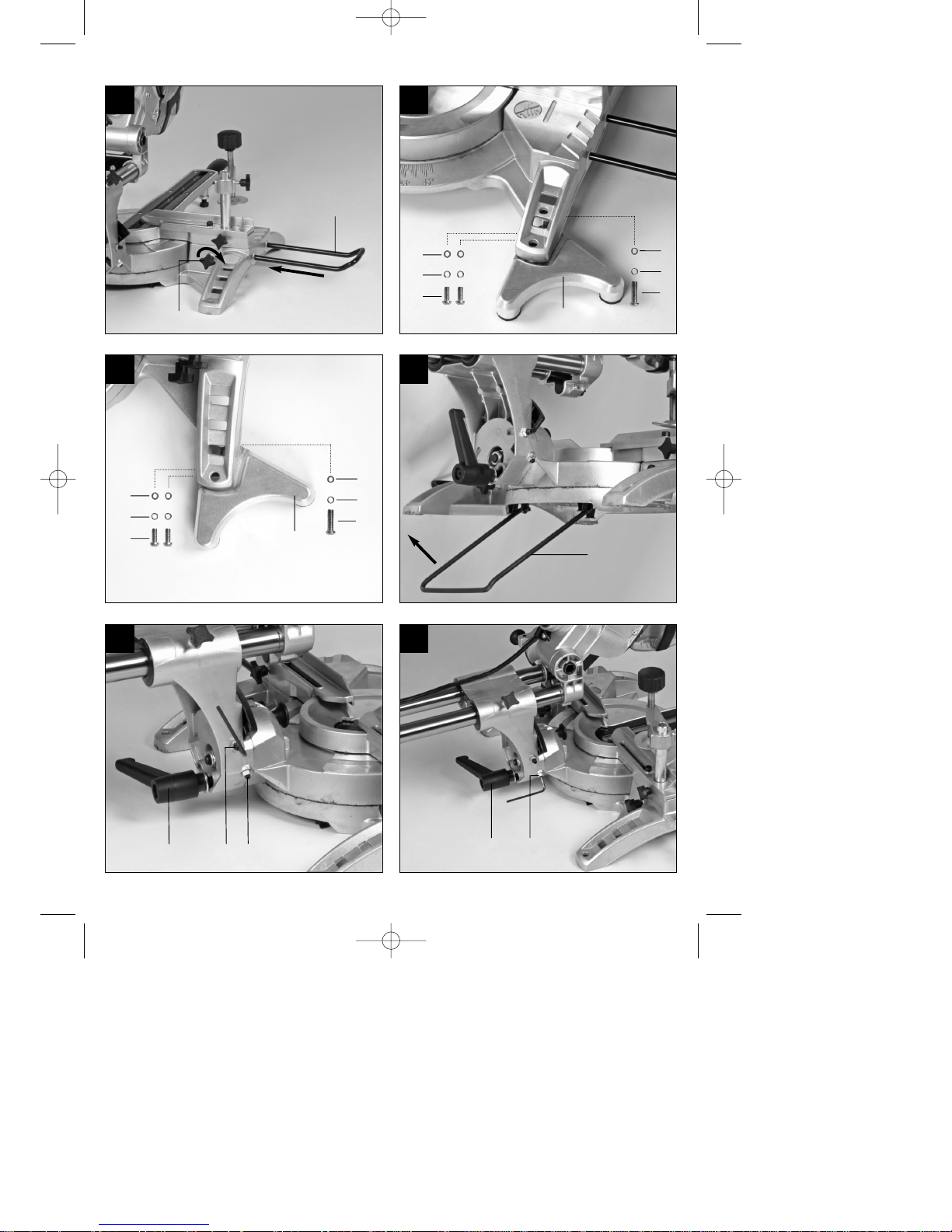
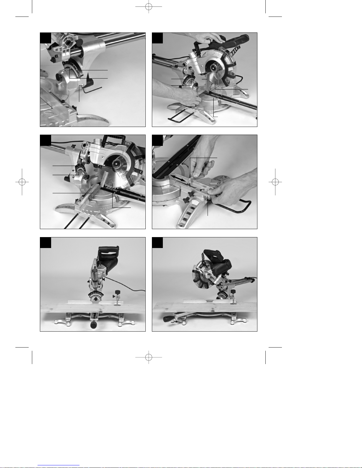
6.2 Säge montieren (Bild 1-5)
Zum Verstellen des Drehtisches (17) die
Feststellschraube (14) ca. 2 Umdrehungen
lockern um den Drehtisch (17) zu entriegeln.
Drehtisch (17) und Zeiger (15) auf das
gewünschte Winkelmaß der Skala (16) drehen
und mit der Feststellschraube (14) fixieren. Die
Säge besitzt Raststellungen bei den Positionen 45°, -31,6°, -22,5°, -15°, 0°, 15°, 22,5°, 31,6° und
45°, an denen der Drehtisch (17) hörbar
einrastet.
Durch leichtes Drücken des Maschinenkopfes (4)
nach unten und gleichzeitiges Herausziehen des
Sicherungsbolzens (25) aus der Motorhalterung,
wird die Säge aus der unteren Stellung
entriegelt. Drehen Sie den Sicherungsbolzen
(25) um 90° bevor sie ihn loslassen, damit die
Säge entriegelt bleibt.
Maschinenkopf (4) nach oben schwenken, bis
der Entriegelungshebel (3) einrastet.
Die Spannvorrichtung (8) kann sowohl links als
auch rechts am feststehenden Sägetisch (18)
montiert werden.
Feststellschrauben für Werkstückauflage (26)
lösen.
Werkstückauflage (10) am feststehenden
Sägetisch (18) montieren, entsprechende
Feststellschraube (26) anziehen (Bild 4).
Die zweite Werkstückauflage (10) auf der
gegenüberliegenden Seite der Säge montieren
und mit der entsprechenden Feststellschraube
(26) sichern.
Der Maschinenkopf (4) kann durch lösen der
Feststellschraube (21), nach links auf max. 45°
geneigt werden.
Um einen sicheren Stand der Säge zu
gewährleisten verstellen Sie den einstellbaren
Standfuß (13), durch Drehung so, dass die Säge
waagerecht und stabil steht.
Schrauben Sie die zusätzlichen Standfüße (9) an
den Füßen des feststehenden Sägetisches (18)
fest.
Klappen sie den Standbügel (36) nach hinten
aus, bis er einrastet.
6.3 Feinjustierung des Anschlags für
Kappschnitt 90° (Bild 7-8)
Den Drehtisch (17) auf 0° Stellung fixieren.
Feststellschraube (21) lockern und mit dem
Handgriff (1) den Maschinenkopf (4) ganz nach
rechts neigen.
90° Anschlagwinkel (a) zwischen Sägeblatt (7)
und Drehtisch (17) anlegen.
Justierschraube (29) soweit verstellen, bis der
Winkel zwischen Sägeblatt (7) und Drehtisch
(17) 90° beträgt.
Überprüfen Sie abschließend die Position des
Zeigers (20) an der Skala (19) Falls erforderlich,
Zeiger (20) mit Kreuzschlitzschraubendreher
lösen, auf 0°-Position der Skala (19) setzen und
Halteschraube wieder festziehen.
Anschlagwinkel nicht im Lieferumfang
enthalten.
6.4 Feinjustierung des Anschlags für
Gehrungsschnitt 45° (Bild 1, 6, 7, 9)
Den Drehtisch (17) auf 0° Stellung fixieren.
Feststellschraube (21) lösen und mit dem
Handgriff (1) den Maschinenkopf (4) ganz nach
links, auf 45° neigen.
45°-Anschlagwinkel (b) zwischen Sägeblatt (7)
und Drehtisch (17) anlegen.
Justierschraube (30) soweit verstellen, dass der
Winkel zwischen Sägeblatt (7) und Drehtisch
(17) genau 45° beträgt.
Anschlagwinkel nicht im Lieferumfang
enthalten.
6.5 Einstellung des Gehrungswinkels am
Maschinenkopf (Bild 2, 12-13)
Lösen die Feststellschraube (21).
Fassen Sie den Maschinenkopf (4) am Griff (1)
Nach Ziehen des Knopfes (33) kann der
Maschinenkopf stufenlos bzw. auch in
verschiedenen Raststellungen geneigt werden.
Winkel nach links: 0-45°
Winkel nach rechts: 0-45°
Feststellschraube (21) wieder festziehen
Anleitung_BT_SM_2131_Dual_SPK7:_ 14.10.2010 15:39 Uhr Seite 12
Page 15

6.6 Einstellung der beweglichen
Anschlagschienen (Bild 1, 10-14)
Achtung! Diese Säge ist mit beweglichen
Anschlagschienen (34) ausgestattet, die an der
feststehenden Anschlagschiene (11) verschraubt
sind.
Für Winkel- bzw. Gehrungsschnitte müssen die
beweglichen Anschlagschienen eingestellt
werden, um eine Kollision mit dem Sägeblatt zu
vermeiden.
Bei Gehrungs- bzw. Winkelschnitten nach links
muss die linke Anschlagschiene nach außen
verschoben werden. Bei Winkelschnitten nach
rechts muss die rechte Anschlagschiene nach
außen verschoben werden. Öffnen Sie die
Feststellschrauben der beweglichen
Anschlagschienen und ziehen Sie die Schienen
soweit zurück, dass eine Kollision mit dem
Sägeblatt ausgeschlossen ist. Ziehen Sie vor
jedem Schnitt die Feststellschrauben der
Anschlagschienen wieder an.
Bei Gehrungsschnitten und
Doppelgehrungsschnitten mit nach rechts
geneigtem Sägekopf muss die rechte
Anschlagschiene komplett abgenommen
werden. Achtung! In diesem Fall verringert sich
die maximal erlaubte Werkstückhöhe (s. 5.
Technische Daten).
Befestigen Sie nach Ende der Arbeiten immer
die bewegliche Anschlagschiene wieder am
Gerät.
Die Anschlagschienen müssen stets beim Gerät
verbleiben. Eine entfernte Anschlagschiene
gefährdet die Betriebssicherheit des Gerätes.
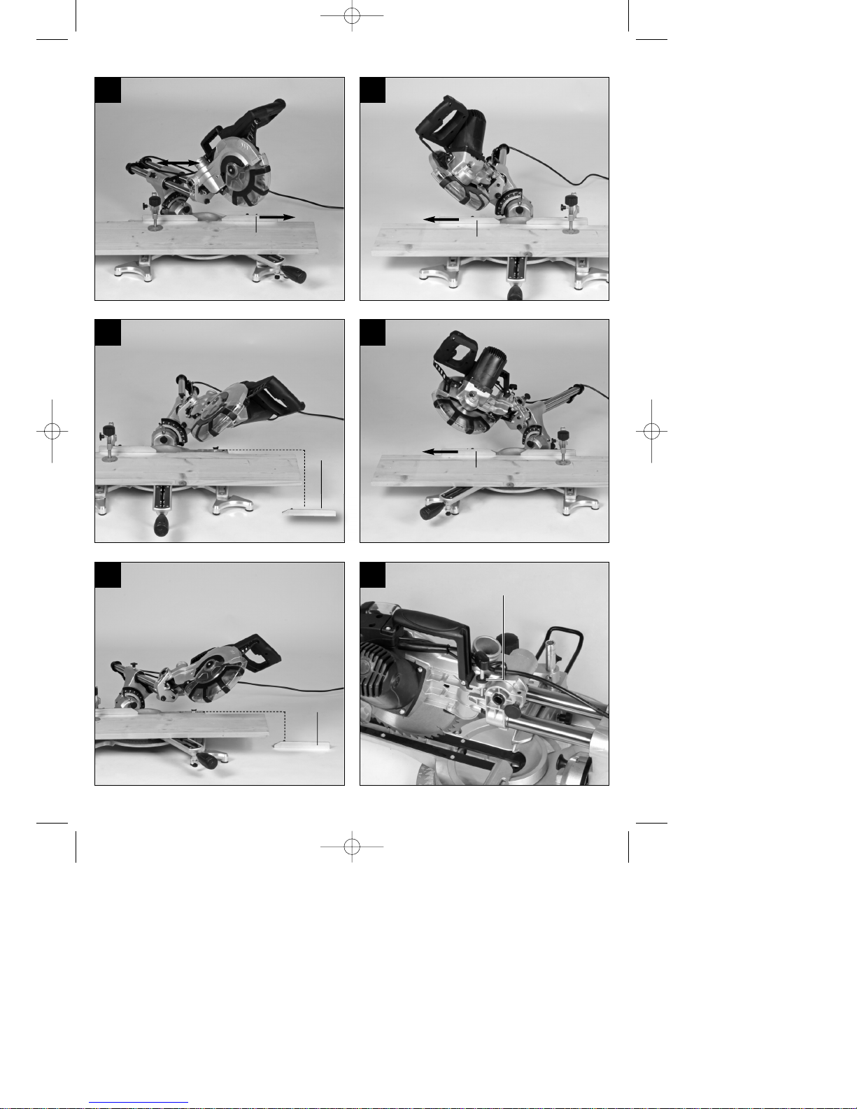
7. Betrieb
7.1 Kappschnitt 90° und Drehtisch 0°
(Bild 1–3, 11)
Bei Schnittbreiten bis ca. 100 mm kann die
Zugfunktion der Säge mit der Feststellschraube für
Zugführung (24) in der hinteren Position fixiert
werden. Sollte die Schnittbreite über 100 mm liegen,
muss darauf geachtet werden, dass die
Feststellschraube für Zugführung (24) locker und der
Maschinenkopf (4) beweglich ist.
Maschinenkopf (4) in die obere Position bringen.
Maschinenkopf (4) am Handgriff (1) nach hinten
schieben und gegebenenfalls in dieser Position
fixieren. (je nach Schnittbreite)
Legen Sie das zu schneidende Holz an die
Anschlagschiene (11) und auf den Drehtisch
(17).
Das Material mit der Spannvorrichtung (8) auf
dem feststehenden Sägetisch (18) feststellen,
um ein Verschieben während des
Schneidvorgangs zu verhindern.
Entriegelungshebel (3) drücken um den
Maschinenkopf (4) freizugeben.
Ein-/ Ausschalter (2) drücken, um den Motor
einzuschalten.
Bei fixierter Zugführung (23): Maschinenkopf (4)
mit dem Handgriff (1) gleichmäßig und mit
leichtem Druck nach unten bewegen, bis das
Sägeblatt (7) das Werkstück durchschnitten hat.
Bei nicht fixierter Zugführung (23):
Maschinenkopf (4) nach ganz vorne ziehen und
dann mit dem Handgriff (1) gleichmäßig und mit
leichtem Druck ganz nach unten absenken. Nun
Maschinenkopf (4) langsam und gleichmäßig
ganz nach hinten schieben, bis das Sägeblatt (7)
das Werkstück vollständig durchschnitten hat.
Nach Beendigung des Sägevorgangs
Maschinenkopf (4) wieder in die obere
Ruhestellung bringen und Ein-/ Ausschalter (2)
loslassen.
Achtung! Durch die Rückholfeder schlägt die
Maschine automatisch nach oben, d.h. Handgriff (1)
nach Schnittende nicht loslassen, sondern
Maschinenkopf (4) langsam und unter leichtem
Gegendruck nach oben bewegen.
7.2 Kappschnitt 90° und Drehtisch 0°- 45°
(Bild 1-3, 12)
Mit der Kappsäge können Kappschnitte von 0° - 45°
nach links und 0° - 45° nach rechts zur
Anschlagschiene ausgeführt werden.
Den Drehtisch (17) durch Lockern der
Feststellschraube (14) lösen.
Drehtisch (17) und Zeiger (15) auf das
gewünschte Winkelmaß der Skala (16) drehen
und mit der Feststellschraube (14) fixieren. Die
Säge besitzt Raststellungen bei den Positionen -
45°, -31,6°, -22,5°, -15°, 0°, 15°, 22,5°, 31,6° und
45°, an denen der Drehtisch (17) hörbar
einrastet.
Die Feststellschraube (14) wieder festziehen, um
den Drehtisch (17) zu fixieren.
Schnitt wie unter Punkt 7.1 beschrieben
ausführen.
13
D
Anleitung_BT_SM_2131_Dual_SPK7:_ 14.10.2010 15:39 Uhr Seite 13
Page 16

14
D
7.3 Gehrungsschnitt 0°- 45° und Drehtisch 0°
(Bild 1–3, 13)
Mit der Kappsäge können Gehrungsschnitte nach
links von 0-45° und nach rechts von 0-45° zur
Arbeitsfläche ausgeführt werden.
Spannvorrichtung (8) gegebenenfalls
demontieren oder auf der gegenüberliegenden
Seite des feststehenden Sägetisches (18)
montieren.
Maschinenkopf (4) in die obere Stellung bringen.
Den Drehtisch (17) auf 0° Stellung fixieren.
Die Einstellung des Gehrungswinkels am
Maschinenkopf und der Anschlagschiene erfolgt,
wie unter Punkt 6.5, 6.6 beschrieben.
Schnitt wie unter Punkt 7.1 beschrieben
ausführen.
7.4 Gehrungsschnitt 0°- 45° und Drehtisch 0°- 45°
(Bild 1–3, 14)
Mit der Kappsäge können Gehrungsschnitte nach
links von 0-45° und nach rechts von 0-45° zur
Arbeitsfläche ausgeführt werden, mit gleichzeitiger
Einstellung des Drehtisches zur Anschlagschiene
von 0°-45° nach links bzw. 0-45° nach rechts
(Doppelgehrungsschnitt).
Spannvorrichtung (8) gegebenenfalls demon-
tieren oder auf der gegenüberliegenden Seite
des feststehenden Sägetisches (18) montieren.
Maschinenkopf (4) in die obere Stellung bringen.
Den Drehtisch (17) durch Lockern der
Feststellschraube (14) lösen.
Mit dem Handgriff (1) den Drehtisch (17) auf den
gewünschten Winkel einstellen (siehe hierzu
auch Punkt 7.2).
Die Feststellschraube (14) wieder festziehen, um
den Drehtisch zu fixieren.
Die Einstellung des Gehrungswinkels am
Maschinenkopf und der Anschlagschiene erfolgt,
wie unter Punkt 6.5, 6.6 beschrieben
Schnitt wie unter Punkt 7.1 beschrieben
ausführen.
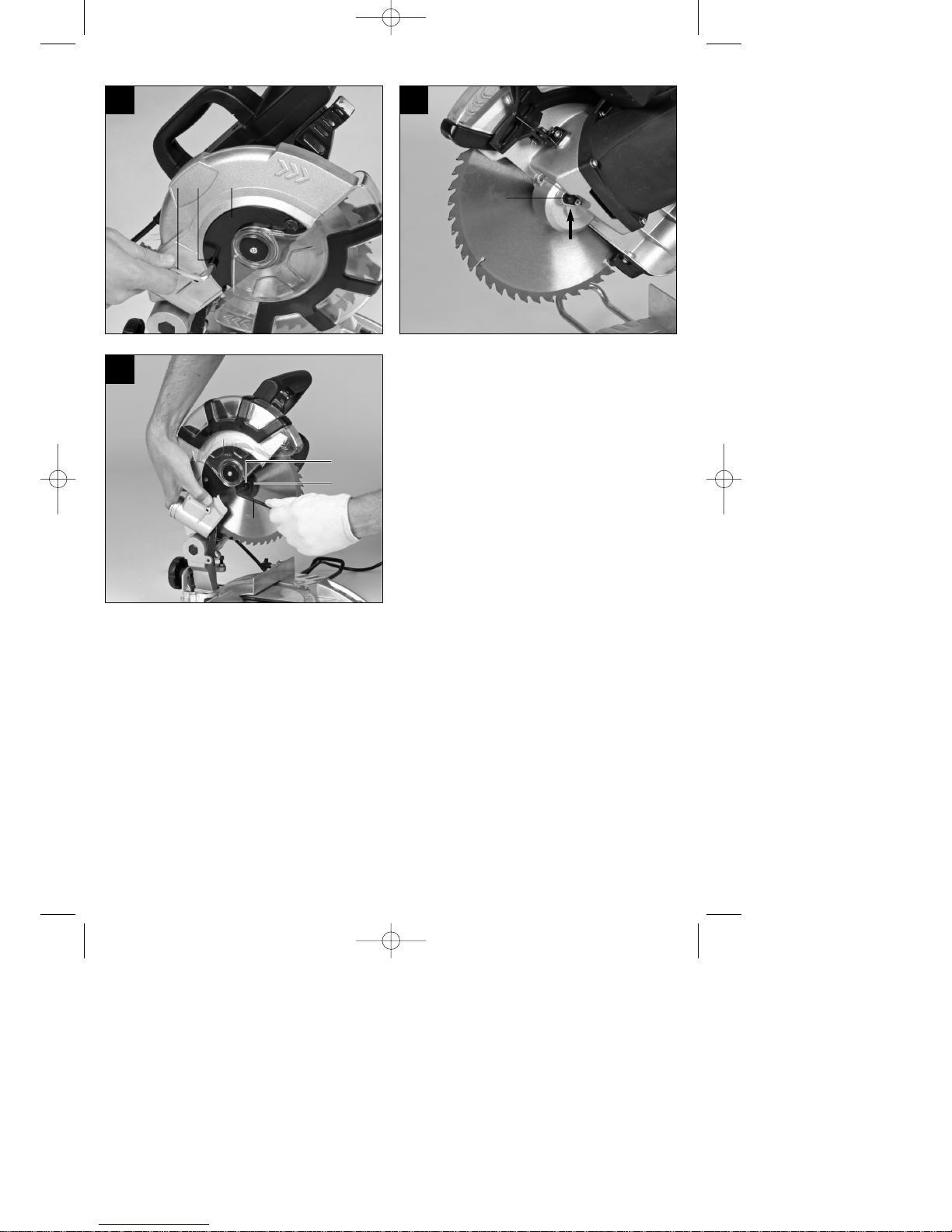
7.5 Schnitttiefenbegrenzung (Bild 15)
Mittels der Schraube (27) kann die Schnitttiefe
stufenlos eingestellt werden. Stellen Sie die
gewünschte Schnitttiefe durch Eindrehen oder
Herausdrehen der Schraube (27) ein und ziehen
Sie die Rändelmutter an der Schraube (27)
anschließend wieder fest.
Überprüfen Sie die Einstellung anhand eines
Probeschnittes.
7.6 Spänefangsack (Abb. 2)
Die Säge ist mit einem Fangsack (22) für Späne
ausgestattet.
Der Spänesack (22) kann über den Reißverschluss
auf der Unterseite entleert werden.
7.7 Austausch des Sägeblatts (Bild 1, 16-18)
Vor Austausch des Sägeblattes: Netzstecker
ziehen!
Tragen Sie beim Sägeblattwechsel Handschuhe,
um Verletzungen zu vermeiden!
Schwenken Sie den Maschinenkopf (4) nach
oben.
Öffnen Sie die Schraube (z) am Abdeckblech (f)
des Sägeblattes
Ziehen Sie den beweglichen Sägeblattschutz (6)
zurück und drehen Sie gleichzeitig das
Abdeckblech, so dass die Flanschschraube
zugänglich wird.
Drücken Sie mit einer Hand die
Sägewellensperre (5) und setzen Sie mit der
anderen Hand den Inbusschlüssel (d) auf die
Flanschschraube (31). Nach max. einer
Umdrehung rastet die Sägewellensperre (5) ein.
Jetzt mit etwas mehr Kraftaufwand
Flanschschraube (31) im Uhrzeigersinn lösen.
Drehen Sie die Flanschschraube (31) ganz her-
aus und nehmen Sie den Außenflansch (32) ab.
Das Sägeblatt (7) vom Innenflansch abnehmen
und nach unten herausziehen.
Flanschschraube (31), Außenflansch (32) und
Innenflansch sorgfältig reinigen.
Das neue Sägeblatt (7) in umgekehrter
Reihenfolge wieder einsetzen und festziehen.
Achtung! Die Schnittschräge der Zähne d.h. die
Drehrichtung des Sägeblattes (7), muss mit der
Richtung des Pfeils auf dem Gehäuse
übereinstimmen.
Bevor Sie mit der Säge weiter arbeiten, ist die
Funktionsfähigkeit der Schutzeinrichtungen zu
prüfen.
Achtung! Nach jedem Sägeblattwechsel prüfen,
ob das Sägeblatt in senkrechter Stellung sowie
auf 45° gekippt, frei in der Tischeinlage (12)
läuft.
Achtung! Das Wechseln und Ausrichten des
Sägeblattes (7) muss ordnungsgemäß
ausgeführt werden.
Anleitung_BT_SM_2131_Dual_SPK7:_ 14.10.2010 15:39 Uhr Seite 14
Page 17

7.8 Transport (Abb. 1-3)
Feststellschraube (14) festziehen, um den
Drehtisch (17) zu verriegeln
Entriegelungshebel (3) betätigen, Maschinenkopf
(4) nach unten drücken und mit
Sicherungsbolzen (25) arretieren. Die Säge ist
nun in der unteren Stellung verriegelt.
Zugfunktion der Säge mit der Feststellschraube
für Zugführung (24) in der hinteren Position
fixieren.
Tragen Sie die Maschine am feststehenden
Sägetisch (18).
Um die Maschine erneut aufzubauen, gehen Sie
nach Punkt 6.2 vor.
7.9 Betrieb Laser (Bild 2)
Einschalten: Bewegen Sie den Ein-/Ausschalter
Laser (37) in Stellung „I“, um den Laser (35)
einzuschalten. Auf das zu bearbeitende Werkstück
wird eine Laserlinie projiziert, die die genaue
Schnittführung anzeigt.
Ausschalten: Bewegen Sie den Ein-/Ausschalter
Laser (37) in Stellung „0“.
8. Austausch der Netzanschlussleitung
Wenn die Netzanschlussleitung dieses Gerätes
beschädigt wird, muss sie durch den Hersteller oder
seinen Kundendienst oder eine ähnlich qualifizierte
Person ersetzt werden, um Gefährdungen zu
vermeiden.
9. Reinigung, Wartung und
Ersatzteilbestellung
Ziehen Sie vor allen Reinigungsarbeiten den
Netzstecker.
9.1 Reinigung
Halten Sie Schutzvorrichtungen, Luftschlitze und
Motorengehäuse so staub- und schmutzfrei wie
möglich. Reiben Sie das Gerät mit einem
sauberen Tuch ab oder blasen Sie es mit
Druckluft bei niedrigem Druck aus.
Wir empfehlen, dass Sie das Gerät direkt nach
jeder Benutzung reinigen.
Reinigen Sie das Gerät regelmäßig mit einem
feuchten Tuch und etwas Schmierseife.
Verwenden Sie keine Reinigungs- oder
Lösungsmittel; diese könnten die Kunststoffteile
des Gerätes angreifen. Achten Sie darauf, dass
kein Wasser in das Geräteinnere gelangen kann.
9.2 Kohlebürsten
Bei übermäßiger Funkenbildung lassen Sie die
Kohlebürsten durch eine Elektrofachkraft überprüfen.
Achtung! Die Kohlebürsten dürfen nur von einer
Elektrofachkraft ausgewechselt werden.
9.3 Wartung
Im Geräteinneren befinden sich keine weiteren zu
wartenden Teile.
9.4 Ersatzteilbestellung:
Bei der Ersatzteilbestellung sollten folgende
Angaben gemacht werden;
Typ des Gerätes
Artikelnummer des Gerätes
Ident-Nummer des Gerätes
Ersatzteilnummer des erforderlichen Ersatzteils
Aktuelle Preise und Infos finden Sie unter
www.isc-gmbh.info
10. Lagerung
Lagern Sie das Gerät und dessen Zubehör an einem
dunklen, trockenen und frostfreiem sowie für Kinder
unzugänglichem Ort. Die optimale Lagertemperatur
liegt zwischen 5 und 30 ˚C. Bewahren Sie das
Elektrowerkzeug in der Originalverpackung auf.
11. Entsorgung und Wiederverwertung
Das Gerät befindet sich in einer Verpackung um
Transportschäden zu verhindern. Diese Verpackung
ist Rohstoff und ist somit wieder verwendbar oder
kann dem Rohstoffkreislauf zurückgeführt werden.
Das Gerät und dessen Zubehör bestehen aus
verschiedenen Materialien, wie z.B. Metall und
Kunststoffe. Führen Sie defekte Bauteile der
Sondermüllentsorgung zu. Fragen Sie im
Fachgeschäft oder in der Gemeindeverwaltung nach!
15
D
Anleitung_BT_SM_2131_Dual_SPK7:_ 14.10.2010 15:39 Uhr Seite 15
Page 18

16
GB
“Caution - Read the operating instructions to reduce the risk of inquiry”
Wear ear-muffs.
The impact of noise can cause damage to hearing.
Wear a breathing mask.
Dust which is injurious to health can be generated when working on wood and other materials.
Never use the device to work on any materials containing asbestos!
Wear safety goggles.
Sparks generated during working or splinters, chips and dust emitted by the device can cause
loss of sight.
Anleitung_BT_SM_2131_Dual_SPK7:_ 14.10.2010 15:39 Uhr Seite 16
Page 19

Table of contents:
1. Safety information
2. Layout
3. Items supplied
4. Intended use
5. Technical data
6. Before starting the equipment
7. Functions
8. Replacing the power cable
9. Cleaning, maintenance and ordering of spare parts
10. Storage
11. Disposal and recycling
17
GB
Anleitung_BT_SM_2131_Dual_SPK7:_ 14.10.2010 15:39 Uhr Seite 17
Page 20
Important.
When using the equipment, a few safety precautions
must be observed to avoid injuries and damage.
Please read the complete operating instructions and
safety information with due care. Keep these
operating instructions in a safe place so that the
information is available at all times. If you give the
equipment to any other person, hand over these
operating instructions and the safety information as
well. We cannot accept any liability for damage or
accidents which arise due to a failure to follow these
instructions and the safety information.
1. Safety information
Please refer to the booklet included in delivery for the
safety information.
CAUTION
Read all the safety regulations and instructions. Any
errors made in following the safety information and
instructions set out below may result in an electric
shock, fire and/or serious injury.
Keep all safety information and instructions in a
safe place for future use.
1.1 Special information about the laser
Important: Laser radiation
Do not look into the beam
Laser class 2
Never look directly into the laser path.
Never direct the laser beam at reflecting surfaces
or persons or animals. Even a low output laser
beam can inflict injury on the eye.
Caution: It is vital to follow the work procedures
described in these instructions. Using the
equipment in any other way may result in
hazardous exposure to laser radiation.
Never open the laser module.
When the crosscut saw is not going to be used for
an extended period of time, the batteries should
be removed.
It is prohibited to carry out any modifications to
the laser to increase its power.
The manufacturer cannot accept any liability for
damage due to non-observance of the safety
information.
2. Layout
1. Handle
2. ON/OFF switch
3. Release lever
4. Machine head
5. Saw shaft lock
6. Adjustable blade guard
7. Saw blade
8. Clamping device
9. Additional feet
10. Workpiece support
11. Fixed stop rail
12. Table insert
13. Adjustable foot
14. Locking screw
15. Pointer
16. Scale
17. Turntable
18. Fixed saw table
19. Scale
20. Pointer
21. Locking screw
22. Sawdust bag
23. Drag guide
24. Locking screw for drag guide
25. Fastening bolt
26. Locking screw for workpiece support
27. Knurled screw for cutting depth limiter
28. Stop for cutting depth limiter
29. Adjusting screw
30. Adjusting screw
31. Flange bolt
32. Outer flange
33. Button
34. Movable stop rail
35. Laser
36. Swing-out stability bar
37. ON/OFF switch for laser
38. Transport handle
18
GB
Anleitung_BT_SM_2131_Dual_SPK7:_ 14.10.2010 15:39 Uhr Seite 18
Page 21
3. Items supplied (Fig. 1-3)
Open the packaging and take out the equipment
with care.
Remove the packaging material and any
packaging and/or transportation braces (if
available).
Check to see if all items are supplied.
Inspect the equipment and accessories for
transport damage.
If possible, please keep the packaging until the
end of the guarantee period.
IMPORTANT
The equipment and packaging material are not
toys. Do not let children play with plastic bags,
foils or small parts.
There is a danger of swallowing or suffocating!
Drag, crosscut and miter saw
Clamping device (8)
2 x workpiece support (10)
Sawdust bag (22)
Allen key (c, d)
Additional feet (9)
Original operating instructions
Safety information
4. Intended use
The drag, crosscut and miter saw is designed to
crosscut wood and plastic respective of the
machine’s size. The saw is not designed for cutting
firewood.
The equipment is to be used only for its prescribed
purpose. Any other use is deemed to be a case of
misuse. The user/operator and not the manufacturer
will be liable for any damage or injuries of any kind
caused as a result of this.
Please note that our equipment has not been
designed for use in commercial, trade or industrial
applications. Our warranty will be voided if the
equipment is used in commercial, trade or industrial
businesses or for equivalent purposes.
The equipment is to be operated only with suitable
saw blades. It is prohibited to use any type of cuttingoff wheel.
To use the equipment properly you must also observe
the safety information, the assembly instructions and
the operating instructions to be found in this manual.
All persons who use and service the equipment have
to be acquainted with these operating instructions
and must be informed about the equipment’s
potential hazards. It is also imperative to observe the
accident prevention regulations in force in your area.
The same applies for the general rules of health and
safety at work.
The manufacturer will not be liable for any changes
made to the equipment nor for any damage resulting
from such changes. Even when the equipment is
used as prescribed it is still impossible to eliminate
certain residual risk factors. The following hazards
may arise in connection with the machine’s
construction and design:
Contact with the saw blade in the uncovered saw
zone.
Reaching into the running saw blade (cut
injuries).
Kick-back of workpieces and parts of workpieces.
Saw blade fracturing.
Catapulting of faulty carbide tips from the saw
blade.
Damage to hearing if ear-muffs are not used as
necessary.
Harmful emissions of wood dust when used in
closed rooms.
5. Technical data
AC motor: 230 V ~ 50Hz
Power: 1500 W S1 / 1800 W S2 5 min
Idle speed n0: 5000 min
-1
Carbide saw blade: ø 210 x ø 30 x 2.8 mm
Number of teeth: 48
Swiveling range: -45° / 0°/ +45°
Miter cut to the left: 0° to 45°
Miter cut to the right: 0° to 45°
Saw width at 90°: 310 x 62 mm
Saw width at 45°: 210 x 62 mm
Saw width at 2 x 45°
(double miter cut left): 210 x 36 mm
Saw width at 2 x 45°
(double miter cut right): 210 x 20 mm
Weight: approx. 11 kg
Laser class: 2
Wavelength of laser: 650 nm
Laser output: ≤ 1 mW
19
GB
Anleitung_BT_SM_2131_Dual_SPK7:_ 14.10.2010 15:39 Uhr Seite 19
Page 22

A load factor of S2 5 min (intermittent periodic duty)
means that you may operate the motor continuously
at its nominal power level (1800 W) for no longer than
the time stipulated on the specifications label (5
minutes ON period). If you fail to observe this time
limit the motor will overheat. During the OFF period
the motor will cool again to its starting temperature.
Sound and vibration
Sound and vibration values were measured in
accordance with EN 61029.
LpAsound pressure level 93 dB(A)
KpAuncertainty 3 dB
LWAsound power level 104 dB(A)
KWAuncertainty 3 dB
Wear ear-muffs.
The impact of noise can cause damage to hearing.
Total vibration values (vector sum of three directions)
determined in accordance with EN 61029.
Vibration emission value a
h
= 2.44 m/s
2
K uncertainty = 1.5 m/s
2
Additional information for electric power tools
Warning!
The specified vibration value was established in
accordance with a standardized testing method. It
may change according to how the electric equipment
is used and may exceed the specified value in
exceptional circumstances.
The specified vibration value can be used to compare
the equipment with another electric power tools.
The specified vibration value can be used for initial
assessment of a harmful effect.
Reduce noise generation and vibration to a
minimum!
Use only equipment that is in perfect condition.
Maintain and clean the equipment regularly.
Adopt your way of working to the equipment.
Do not overload the equipment.
Have the equipment checked if necessary.
Switch off the equipment when not in use.
Residual risks
Even if you use this electric power tool in
accordance to instructions, certain residual risks
cannot be eliminated. The following hazards may
arise in connection with the equipment’s
construction and layout:
1. Lung damage if no suitable protective dust mask
is applied.
2. Damage to hearing if no suitable ear protection is
applied.
3. Health damage caused by hand-arm vibrations if
the equipment is used over a longer period or is
not properly guided and maintained.
6. Before starting the equipment
6.1 General information
The equipment must be set up where it can stand
securely, i.e. it should be bolted to a workbench,
a universal base frame or similar.
All covers and safety devices have to be properly
fitted before the equipment is switched on.
It must be possible for the blade to run freely.
When working with wood that has been
processed before, watch out for foreign bodies
such as nails or screws, etc.
Before you actuate the On/Off switch, make sure
that the saw blade is correctly fitted and that the
equipment’s moving parts run smoothly.
Check that the voltage on the rating plate is the
same as your supply voltage before you connect
the equipment to the power supply.
Pull out the power plug before carrying out any
assembly and adjustment work.
6.2 Assembling the saw (Fig. 1-5)
To adjust the turntable (17), loosen the locking
screw (14) by approx. 2 turns, which frees the
turntable (17).
Turn the turntable (17) and scale pointer (15) to
the desired angular setting on the dial (16) and
lock into place with the locking screw (14). The
saw has locking positions at angles of - 45°, -
31.6°, -22.5°, -15°, 0°, 15°, 22.5°, 31.6° and 45°,
at which the turntable (17) audibly clicks into
position.
To release the saw from its position at the bottom,
pull the fastening bolt (25) out of the motor
mounting while pressing down lightly on the
machine head (4). Turn the fastening bolt (25)
through 90° before releasing it, so that the saw
remains unlocked.
Swing the machine head (4) up until the release
lever (3) latches into place.
The clamping device (8) can be fitted on the left
20
GB
Anleitung_BT_SM_2131_Dual_SPK7:_ 14.10.2010 15:39 Uhr Seite 20
Page 23

or right of the fixed saw table (18).
Undo the locking screws for the workpiece
support (26).
Mount the workpiece support (10) on the fixed
saw table (18) and tighten the appropriate locking
screw (26) (Figure 4).
Mount the second workpiece support (10) on the
opposite side of the saw and secure with the
appropriate locking screw (26).
When the locking screw (21) is loosened, you can
tilt the machine head (4) to the left by up to 45°.
To ensure that the saw is standing securely,
adjust the adjustable foot (13) by turning it so that
the saw stands in a horizontal and firm position.
Screw the additional feet (9) to the feet of the
fixed saw table (18).
Then swing out the stability bar (36) to the rear
until it engages.
6.3 Precision adjustment of the stop for crosscut
90° (Fig. 7-8)
Fasten the turntable (17) in 0° position.
Undo the locking screw (21) and move the
machine head (4) all the way to the right using the
handle (1).
Place the 90° angular stop (a) between the blade
(7) and the turntable (17).
Adjust the adjustment screw (29) until the angle
between the blade (7) and the turntable (17)
equals 90°.
Finally check the position of the pointer (20) on
the scale (19). If necessary, undo the pointer (20)
with a Philips screwdriver, set it to the 0° position
on the scale (19) and retighten the retainer screw.
No stop angle included.
6.4 Precision adjustment of the stop for miter cut
45° (Fig. 1, 6, 7, 9)
Fasten the turntable (17) in 0° position.
Undo the locking screw (21) and move the
machine head (4) all the way to the left using the
handle (1), until it coincides at 45°.
Place the 45° stop angle (b) between the blade
(7) and the turntable (17).
Adjust the adjustment screw (30) so that the
angle between the blade (7) and the turntable
(17) equals exactly 45°.
No stop angle included.
6.5 Adjusting the miter angle on the machine
head (Fig. 2, 12-13)
Undo the locking screw (21).
Hold the machine head (4) by the handle (1).
After pulling the button (33), the machine head
can be tipped infinitely as well as to several
locking points.
Angles to the left: 0-45°
Angles to the right: 0-45°
Re-tighten the locking screw (21).
6.6 Adjusting the movable stop rails
(Fig. 1, 10-14)
Important. This saw is equipped with movable
stop rails (34) that are screwed to the fixed stop
rail (11).
For carrying out angle and miter cuts the movable
stop rails must be adjusted to prevent a collision
with the saw blade.
For miter and angle cuts to the left, the left stop
rail must be moved outwards. For angle cuts to
the right, the right stop rail must be moved
outwards. Undo the locking screws on the
movable stop rails and pull the rails back so far
that a collision with the saw blade can be ruled
out. Prior to every cut retighten the locking screws
of the stop rails.
For miter cuts and double miter cuts with the saw
head tilted to the right, the right stop rail must be
removed completely. Important! In this case the
maximum permissible workpiece height is
reduced (see 5. Technical data).
Always fasten the movable stop rails back to the
equipment again after you have completed your
work.
The stop rails must always remain together with
the equipment. A removed stop rail will impair the
operational safety of the equipment.
7. Functions
7.1 Cross cut 90° and turntable 0° (Fig. 1-3, 11)
For cutting widths up to approx. 100 mm it is possible
to fix the saw’s drag function with the locking screw
for drag guide (24) in rear position. If the cutting width
exceeds 100 mm, you must ensure that the locking
screw for drag guide (24) is slackened and that the
machine head (4) can be moved.
Move the machine head (4) to its upper position.
Use the handle (1) to push back the machine
head (4) and fix it in this position if required
(dependent on the cutting width).
Place the piece of wood to be cut at the stop rail
(11) and on the turntable (17).
Lock the material with the clamping device (8) on
the fixed saw table (18) to prevent the material
from moving during the cutting operation.
Push down the release lever (3) to release the
machine head (4).
Press the ON/OFF switch (2) to start the motor.
With the drag guide (23) fixed in place: Use the
handle (1) to move the machine head (4) steadily
21
GB
Anleitung_BT_SM_2131_Dual_SPK7:_ 14.10.2010 15:39 Uhr Seite 21
Page 24

and with light pressure downwards until the saw
blade (7) has completely cut through the
workpiece.
With the drag guide (23) not fixed in place: Pull
the machine head (4) all the way to the front and
then use the handle to move it downwards
steadily and with light pressure. Now push the
machine head (4) slowly and steadily to the very
back until the saw blade (7) has completely cut
through the workpiece.
When the cutting operation is completed, move
the machine head (4) back to its upper (home)
position and release the ON/OFF button (2).
Important. The integral resetting springs will
automatically lift the machine head. Do not simply let
go of the handle (1) after cutting, but allow the
machine head (4) to rise slowly, applying slight
counter pressure as it does so.
7.2 Cross cut 90° and turntable 0° - 45°
(Fig. 1-3, 12)
The crosscut saw can be used to make crosscuts of
0°- 45° to the left and 0° - 45° to the right in relation to
the stop rail.
Release the turntable (17) by slackening the
locking screw (14).
Turn the turntable (17) and scale pointer (15) to
the desired angular setting on the dial (16) and
lock into place with the locking screw (14). The
saw has locking positions at angles of - 45°, -
31.6°, -22.5°, -15°, 0°, 15°, 22.5°, 31.6° and 45°,
at which the turntable (17) audibly clicks into
position.
Retighten the locking screw (14) to secure the
turntable (17) in place.
Cut as described under section 7.1.
7.3 Miter cut 0°- 45° and turntable 0° (Fig. 1-3, 13)
The crosscut saw can be used to make miter cuts to
the left of 0°-45° and to the right of 0°-45° in relation
to the work surface.
If required, dismantle the clamping device (8) or
mount on the opposite side of the fixed saw table
(18).
Move the machine head (4) to its upper position.
Fasten the turntable (17) in 0° position.
Adjust the miter angle on the machine head and
the stop rail as described under points 6.5 and
6.6.
Cut as described under section 7.1.
7.4 Miter cut 0°- 45° and turntable 0°- 45°
(Fig. 1-3, 14)
The crosscut saw can be used to make miter cuts to
the left of 0°-45° and to the right of 0°-45° in relation
to the work surface, with simultaneous setting of the
turntable from 0°-45° to the left or 0°-45° to the right in
relation to the stop rail (double miter cut).
If required, dismantle the clamping device (8) or
mount on the opposite side of the fixed saw table
(18).
Move the machine head (4) to its upper position.
Release the turntable (17) by slackening the
locking screw (14).
Use the handle (1) to adjust the turntable (17) to
the angle required (in this connection see also
section 7.2).
Retighten the locking screw (14) to secure the
turntable in place.
Adjust the miter angle on the machine head and
the stop rail as described under points 6.5 and
6.6.
Cut as described under section 7.1.
7.5 Limiting the cutting depth (Fig. 15)
The cutting depth can be infinitely adjusted using
the screw (27). Turn the screw (27) in or out to set
the required cutting depth and then retighten the
knurled nut on the screw (27).
Check the setting by completing a test cut.
7.6 Sawdust bag (Fig. 2)
The saw is equipped with a debris bag (22) for
sawdust and chips.
The debris bag (22) can be emptied by means of a
zipper at the bottom (1).
7.7 Changing the saw blade (Fig. 1, 16-18)
Before changing the saw blade: Remove the
power plug!
Wear work gloves to prevent injury when
changing the saw blade.
Swing the machine head upwards (4).
Undo the screw (z) on the cover plate (f) of the
saw blade.
Pull back the adjustable blade guard (6) and at
the same time turn the cover plate to achieve
access to the flange bolt.
Press the saw shaft lock (5) with one hand while
positioning the Allen key (d) on the flange bolt
(31) with the other hand. The saw shaft lock (5)
engages after no more than one rotation.
Now, using a little more force, slacken the flange
screw (31) in the clockwise direction.
Turn the flange screw (31) right out and remove
the external flange (32).
Take the blade (7) off the inner flange and pull out
22
GB
Anleitung_BT_SM_2131_Dual_SPK7:_ 14.10.2010 15:39 Uhr Seite 22
Page 25

downwards.
Carefully clean the flange screw (31), outer flange
(32) and inner flange.
Fit and fasten the new saw blade (7) in reverse
order.
Important. The cutting angle of the teeth, in other
words the direction of rotation of the saw blade
(7) must coincide with the direction of the arrow
on the housing.
Check to make sure that all safety devices are
properly mounted and in good working condition
before you begin working with the saw again.
Important. Every time that you change the saw
blade, check to see that it spins freely in the table
insert(12) in both perpendicular and 45° angle
settings.
Important. The work to change and align the saw
blade (7) must be carried out correctly.
7.8 Transport (Fig. 1-3)
Retighten the locking screw (14) to secure the
turntable (17) in place.
Activate the release lever (3), press the machine
head (4) downwards and secure with the safety
pin (25). The saw is now locked in its bottom
position.
Fix the saw’s drag function with the locking screw
for drag guide (24) in rear position.
Carry the equipment by the fixed saw table (18).
To set up the equipment again, proceed as
described in section 6.2.
7.9 Operating the laser (Fig. 2)
To switch on: Move the ON/OFF switch (37) to the
“I” position to switch on the laser (35). A laser line is
projected onto the material you wish to process,
providing an exact guide for the cut.
To switch off: Move the ON/OFF switch (37) to the
“0” position.
8. Replacing the power cable
If the power cable for this equipment is damaged, it
must be replaced by the manufacturer or its aftersales service or similarly trained personnel to avoid
danger.
9. Cleaning, maintenance and ordering
of spare parts
Always pull out the power plug before starting any
cleaning work.
9.1 Cleaning
Keep all safety devices, air vents and the motor
housing free of dirt and dust as far as possible.
Wipe the equipment with a clean cloth or blow it
down with compressed air at low pressure.
We recommend that you clean the equipment
immediately after you use it.
Clean the equipment regularly with a damp cloth
and some soft soap. Do not use cleaning agents
or solvents; these may be aggressive to the
plastic parts in the equipment. Ensure that no
water can get into the interior of the equipment.
9.2 Carbon brushes
In case of excessive sparking, have the carbon
brushes checked only by a qualified electrician.
Important. The carbon brushes should not be
replaced by anyone but a qualified electrician.
9.3 Servicing
There are no parts inside the equipment which
require additional maintenance.
9.4 Ordering replacement parts:
Please provide the following information on all orders
for spare parts:
Model/type of the equipment
Article number of the equipment
ID number of the equipment
Spare part number of the required spare part
For our latest prices and information please go to
www.isc-gmbh.info
10. Storage
Store the equipment and accessories out of children’s
reach in a dark and dry place at above freezing
temperature. The ideal storage temperature is
between 5 and 30 °C. Store the electric tool in its
original packaging.
23
GB
Anleitung_BT_SM_2131_Dual_SPK7:_ 14.10.2010 15:39 Uhr Seite 23
Page 26

11. Disposal and recycling
The equipment is supplied in packaging to prevent it
from being damaged in transit. The raw materials in
this packaging can be reused or recycled.
The equipment and its accessories are made of
various types of material, such as metal and plastic.
Defective components must be disposed of as
special waste. Ask your dealer or your local council.
24
GB
Anleitung_BT_SM_2131_Dual_SPK7:_ 14.10.2010 15:39 Uhr Seite 24
Page 27
25
F
« Avertissement – Lisez ce mode d’emploi pour diminuer le risque de blessures »
Portez une protection de l’ouïe.
L’exposition au bruit peut entraîner une perte de l’ouïe.
Portez un masque anti-poussière.
Lors de travaux sur su bois et autres matériaux, de la poussière nuisible à la santé peut être
dégagée. Ne travaillez pas sur du matériau contenant de l’amiante !
Portez des lunettes de protection.
Les étincelles générées pendant travail ou les éclats, copeaux et la poussière sortant de
l’appareil peuvent entraîner une perte de la vue.
Anleitung_BT_SM_2131_Dual_SPK7:_ 14.10.2010 15:39 Uhr Seite 25
Page 28

Sommaire :
1. Consignes de sécurité
2. Description de l’appareil
3. Volume de livraison
4. Utilisation conforme à l’affectation
5. Caractéristiques techniques
6. Avant la mise en service
7. Fonctionnement
8. Remplacement de la ligne de raccordement réseau
9. Nettoyage, maintenance et commande de pièces de rechange
10. Stockage
11. Mise au rebut et recyclage
26
F
Anleitung_BT_SM_2131_Dual_SPK7:_ 14.10.2010 15:39 Uhr Seite 26
Page 29
Attention !
Lors de l’utilisation d’appareils, il faut respecter
certaines mesures de sécurité afin d’éviter les
blessures et dommages. Veuillez donc lire
attentivement ce mode d’emploi/ces consignes de
sécurité. Veillez à le conserver en bon état pour
pouvoir accéder aux informations à tout moment. Si
l’appareil doit être remis à d’autres personnes, veillez
à leur remettre aussi ce mode d’emploi/ces
consignes de sécurité. Nous déclinons toute
responsabilité pour les accidents et dommages dus
au non-respect de ce mode d’emploi et des
consignes de sécurité.
1. Consignes de sécurité
Vous trouverez les consignes de sécurité
correspondantes dans le petit manuel ci-joint !
AVERTISSEMENT
Veuillez lire toutes les consignes de sécurité et
instructions. Tout manque d’observation des
consignes de sécurité indiquées plus loin peut
entraîner des décharges électriques, un incendie
et/ou de graves blessures.
Conservez toutes les consignes de sécurité et
toutes les instructions pour l’avenir.
1.1 Indications particulières relatives au laser
Attention : Rayon laser
Ne pas regarder en direction du rayon
Classe de laser 2
Ne regardez jamais directement dans le faisceau
des rayons.
Le rayon laser ne doit jamais être dirigé sur des
surfaces réverbérantes, ni sur des animaux ou
personnes. Même un rayon laser de faible
puissance peut occasionner des dommages aux
yeux.
Attention - si vous procédez d’autre manière que
celle indiquée ici, cela peut entraîner une
exposition dangereuse au rayon.
Ne jamais ouvrir le module du laser.
Retirez les batteries de l’appareil s’il reste
longtemps inutilisé.
Il est interdit de procéder à des modifications sur
le laser afin d’en augmenter la puissance.
Le fabricant décline toute responsabilité pour les
dommages dus au non-respect de ce mode
d’emploi.
2. Description de l’appareil
1. Poignée
2. Interrupteur Marche/Arrêt
3. Levier de déverrouillage
4. Tête de la machine
5. Blocage de l’arbre de scie
6. Protection de la lame de scie amovible
7. Lame de scie
8. Dispositif tendeur
9. Pieds d’appui supplémentaires
10. Support de pièce à usiner
11. Rail de butée fixe
12. Insertion de table
13. Pied d’appui réglable
14. Vis de fixation
15. Pointeur
16. Graduation
17. Table tournante
18. Table de menuisier fixe
19. Graduation
20. Pointeur
21. Vis de fixation
22. Sac collecteur de sciures
23. Guidage tiré
24. Vis de fixation pour guidage tiré
25. Boulon de sécurité
26. Vis de fixation pour support de pièce à usiner
27. Vis moletée pour limitation de profondeur de
coupe
28. Butée pour limitation de profondeur de coupe
29. Vis d’ajustage
30. Vis d’ajustage
31. La vis à bride
32. Bride extérieure
33. Bouton
34. Rail de butée mobile
35. Laser
36. Support pliable
37. Interrupteur Marche / Arrêt laser
38. Poignée de transport
27
F
Anleitung_BT_SM_2131_Dual_SPK7:_ 14.10.2010 15:39 Uhr Seite 27
Page 30

3. Volume de livraison (figure 1-3)
Ouvrez l’emballage et sortez-en l’appareil avec
précaution.
Retirez le matériel d’emballage tout comme les
sécurités d’emballage et de transport (s’il y en a).
Vérifiez que le contenu de la livraison est bien
complet.
Vérifiez que l’appareil et les pièces accessoires
n’ont pas subis de dommages.
Conservez l’emballage autant que possible
jusqu’à la fin de la période de garantie.
ATTENTION
L’appareil et les matériaux d’emballage ne sont
pas des jouets !Il est interdit de laisser des
enfants jouer avec des sacs et des films en
plastique et avec des pièces de petite taille !
Ils risquent de les avaler et de s’étouffer !
Scie à onglet radiale
Dispositif tendeur (8)
2 x support de pièces à usiner (10)
Sac collecteur de sciures (22)
Clé à six pans creux (c, d)
Pieds d’appui supplémentaires (9)
Mode d’emploi d’origine
Consignes de sécurité
4. Utilisation conforme à l’affectation
La scie à onglet radiale sert au découpage de bois et
de plastique selon la taille de la machine. La scie ne
convient pas pour le découpage de bois de
chauffage.
La machine doit exclusivement être employée
conformément à son affectation. Toute utilisation
dépassant ce cadre est déclarée non conforme. Pour
les dommages en résultant, ainsi que pour les
blessures de tout genre, le fabricant décline toute
responsabilité et l’opérateur/l’exploitant est
responsable.
Veillez au fait que nos appareils, conformément au
règlement, n’ont pas été conçus pour être utilisés
dans un environnement professionnel, industriel ou
artisanal. Nous déclinons toute responsabilité si
l’appareil venait à être utilisé professionnellement,
artisanalement ou par des sociétés industrielles, tout
comme pour toute activité équivalente.
Seules les lames de scie correspondant au modèle
de la machine doivent être utilisées. L’utilisation de
meules tronçonneuses quel qu’en soit le modèle est
interdite.
Le respect des consignes de sécurité, du mode
d’emploi et des remarques de service dans le mode
d’emploi est aussi partie intégrante de l’utilisation
conforme à l’affectation.
Les personnes commandant la machine et en
effectuant la maintenance doivent la connaître et
avoir été instruites sur les différents risques possibles
en découlant. En outre, il faut strictement respecter
les règlements de prévoyance contre les accidents. Il
faut respecter toutes les autres règles des domaines
de la médecine du travail et de la technique de
sécurité.
Toute modification de la machine entraîne
l’annulation de la responsabilité du producteur, de
même pour les dommages en découlant. Malgré
l’emploi conforme à l’affectation, certains facteurs de
risque résiduels ne peuvent être complètement
supprimés. En raison de la construction et de la
conception de la machine, les risques suivants
peuvent apparaître :
Contact avec la lame de scie dans la zone de la
scie n’étant pas recouverte.
Toucher la lame de scie en fonctionnement
(blessure coupante).
Retour de pièces à usiner et de parties de celles-
ci.
Ruptures de lame de scie.
Expulsion de pièces de métal dures
défectueuses de la lame de scie.
Troubles de l’ouïe si vous n’employez pas la
protection des oreilles nécessaire.
Émissions nocives de poussière de bois en cas
d’emploi de la scie dans des pièces fermées.
28
F
Anleitung_BT_SM_2131_Dual_SPK7:_ 14.10.2010 15:39 Uhr Seite 28
Page 31

5. Caractéristiques techniques
Moteur à courant alternatif : 230 V ~ 50 Hz
Puissance : 1500 W S1 / 1800 W S2 5 min
Vitesse de rotation à vide n0: 5000 tr/min
Lame de scie en métal dur : Ø 210 x Ø 30 x 2,8 mm
Nombre de dents : 48
Zone de pivotement : -45° / 0°/ +45°
Coupe d’onglet vers la gauche : 0° à 45°
Coupe d’onglet vers la droite : 0° à 45°
Largeur de scie à 90° : 310 x 62 mm
Largeur de scie à 45° : 210 x 62 mm
Largeur de la scie à 2 x 45°
(Coupe d’onglet double gauche) : 210 x 36 mm
Largeur de la scie à 2 x 45°
(Coupe d’onglet double droit) : 210 x 20 mm
Poids : env. 11 kg
Classe de laser : 2
Longueur d’ondes du laser : 650 nm
Puissance laser : ≤ 1 mW
La durée de fonctionnement S2 5 min
(fonctionnement de courte durée) indique que le
moteur à puissance nominale (1800 W) ne peut être
maintenu en service que pour la durée indiquée (5
min) sur la plaque signalétique. Dans le cas contraire,
il chaufferait au delà du seuil autorisé. Pendant la
pause le moteur se refroidit jusqu’à retrouver sa
température d’origine.
Bruit et vibrations
Le bruit et les vibrations ont été déterminés
conformément à EN 61029.
Niveau de pression acoustique L
pA
93 dB(A)
Insécurité K
pA
3 dB
Niveau de puissance acoustique L
WA
104 dB (A)
Insécurité K
WA
3 dB
Portez une protection de l’ouïe.
L’exposition au bruit peut entraîner une perte de
l’ouïe.
Les valeurs totales des vibrations (sommes
vectorielles dans trois directions) ont été déterminées
conformément à EN 61029.
Valeur d’émission de vibration a
h
= 2,44 m/s²
Imprécision K = 1,5 m/s²
Informations supplémentaires relatives aux
appareils électriques
Avertissement !
La valeur d’émission de vibration indiquée a été
mesurée selon une méthode d’analyse standard et
peut varier selon la manière dont l’appareil électrique
est utilisé et dans des cas exceptionnels se trouver
au-dessus de la valeur indiquée.
La valeur d’émission de vibration indiquée peut être
utilisée avec un autre appareil électrique à des fins de
comparaison.
La valeur d’émission de vibration indiquée peut être
également utilisée à des fins d’estimation préliminaire
des dommages.
Limitez le niveau sonore et les vibrations à un
minimum !
N’utilisez que des appareils en bon état.
Effectuez une maintenance et un nettoyage
réguliers de l’appareil.
Adaptez votre manière de travailler à l’appareil.
Ne surchargez pas l’appareil.
Faites vérifier l’appareil le cas échéant.
Mettez l’appareil hors circuit lorsque vous ne
l’utilisez pas.
Risques résiduels
Même si vous utilisez cet appareil selon les
règles, des risques résiduels subsistent. Les
dangers suivants peuvent apparaître en rapport
avec le mode de fabrication et le modèle de
l’appareil électrique :
1. Lésions aux poumons si on ne porte pas de
masque anti-poussière approprié.
2. Lésions de l’ouïe si on ne porte pas de protection
appropriée sur les oreilles.
3. Troubles de la santé en raison des vibrations
transmises au système main-bras si l’appareil est
utilisé pendant une longue durée ou ne l’est pas
correctement et, n’est pas entretenu.
29
F
Anleitung_BT_SM_2131_Dual_SPK7:_ 14.10.2010 15:39 Uhr Seite 29
Page 32

6. Avant la mise en service
6.1 Généralités
La machine doit être placée de façon à être bien
stable, autrement dit vissée à fond sur un établi,
un support fixe universel, ou autre.
Avant la mise en service, les recouvrements et
dispositifs de sécurité doivent être montés dans
les règles de l’art.
La lame de scie doit pouvoir tourner sans
obstacle.
Si le bois a déjà été travaillé, faire attention aux
corps étrangers comme par exemple les clous ou
les vis.
Avant d’actionner l’interrupteur Marche / Arrêt,
assurez-vous que la lame de scie est
correctement montée et que les pièces
amovibles sont manœuvrables.
Assurez-vous avant de connecter la machine que
les données se trouvant sur la plaque de
signalisation correspondent bien aux données du
réseau.
Retirez la prise du réseau avant tout travail de
montage et de réglage.
6.2 Monter la scie (fig. 1 à 5)
Pour régler la table tournante (17), dévissez la vis
de fixation (14) d’env. 2 tours pour déverrouiller la
table tournante (17).
Tournez la table tournante (17) et le pointeur
(15)à la cote d’angle désirée de la graduation
(16)et fixez à l’aide de la vis de fixation (14). La
table tournante (17) peut s’encranter de façon
audible aux positions - 45°, -31,6°, -22,5°, -15°,
0°, 15°, 22,5°, 31,6° et45° de la scie.
En appuyant légèrement sur la tête de la machine
(4) vers le bas et en retirant simultanément le
boulon de sécurité (25) du support du moteur, la
scie est déverrouillée à partir de la position
inférieure. Tournez le boulon de sécurité(25) de
90° avant de le relâcher, afin que la scie reste
déverrouillée.
Pivotez la tête de la machine (4) vers le haut
jusqu’à ce que le levier de déverrouillage (3)
s’enclenche.
Le dispositif tendeur (8) peut être monté tout
autant à gauche qu’à droite, de la table de scie
fixe (18).
Desserrez les vis de fixation du support de pièces
(26).
Montez le support des pièces (10) sur la table de
menuisier (18), serrez les vis de fixation(26)
correspondantes (figure 4).
Montez le deuxième support des pièces (10) sur
le côté opposé de la scie et bloquez-le avec la vis
de fixation (26) correspondante.
La tête de la machine (4) peut être inclinée vers la
gauche de maxi. 45°en dévissant la vis de
serrage (21).
Afin de garantir une position stable de la scie,
réglez le pied d’appui réglable(13) par rotation de
façon que la scie soit à l’horizontale et bien
stable.
Vissez les pieds d’appui supplémentaires (9) aux
pieds de la table de menuisier (18).
Dépliez l’armature transversale stationnaire (36)
vers l’arrière jusqu’à ce qu’elle s’enclenche.
6.3 Réglage de précision de la butée pour le
tronçonnage à 90° (fig. 7-8)
Fixez la table tournante (17) en position 0°.
Desserrez la vis de fixation (21) et faites pencher
la tête de la machine (4) vers la droite avec la
poignée (1).
Amenez une équerre de butée (a) entre la lame
(7) et la table tournante (17).
Déplacez la vis d’ajustage (29) jusqu’à ce que
l’angle entre la lame (7) et la table tournante(17)
soit de 90°.
Vérifiez ensuite la position du pointeur (20) sur la
graduation (19). Si nécessaire, desserrer le
pointeur (20) avec un tournevis cruciforme,
l’amener sur la position 0° de la graduation et
resserrer la vis.
L’équerre de butée n’est pas comprise dans
la livraison.
6.4 Réglage de précision pour la coupe d’onglet
à 45° (fig. 1, 6, 7, 9)
Fixez la table tournante (17) en position 0°.
Desserrez la vis de fixation (21) et faites pencher
la tête de la machine (4) sur 45°vers la gauche
avec la poignée (1).
Amenez l’équerre de butée 45° (b) entre la lame
(7) et la table tournante (17).
Déplacez la vis d’ajustage (30) jusqu’à ce que
l’angle entre la lame (7) et la table tournante(17)
soit de 45°.
L’équerre de butée n’est pas comprise dans
la livraison.
6.5 Réglage de l’angle de coupe à la tête de la
machine (fig. 2, 12-13)
Desserrez la vis de fixation (21).
Tenez la tête de la machine (4) à la poignée (1)
Après avoir tiré le bouton (33), on peut pencher la
tête de la machine en continu, ou la placer dans
différentes positions d’encrantement.
Angle vers la gauche : 0°-45°
Angle vers la droite : 0°-45°
Resserrez la vis de fixation (21)
30
F
Anleitung_BT_SM_2131_Dual_SPK7:_ 14.10.2010 15:39 Uhr Seite 30
Page 33

6.6 Réglage des rails de butée mobiles
(fig. 1, 10-14)
Attention ! Cette scie est équipée de rails de
butée (34) mobiles qui sont vissés sur le rail de
butée fixe (11).
Pour les coupes d’onglet ou d’angle, il faut ajuster
les rails de butée mobiles pour éviter une collision
avec la lame de scie.
Pour les couples d’onglet ou d’angle vers la
gauche, il faut pousser le rail de butée gauche
vers l’extérieur. Pour les coupes d’angle vers la
droite, il faut pousser le rail de butée droit vers
l’extérieur. Desserrez la vis de fixation des rails
de butée mobiles et repoussez les rails de telle
manière qu’une collision avec la lame de scie
puisse être évitée. Avant chaque coupe,
resserrez à nouveau les vis de fixation des rails
de butée.
Pour les coupes d’onglet et les coupes d’onglet
doubles avec la tête de scie penchée vers la
droite, il faut enlever complètement le rail de
butée droit. Attention ! Dans ce cas, la hauteur
maximale des pièces à travailler se réduit (Voir
p.5 Caractéristiques techniques).
à la fin des travaux, veillez à toujours à refixer les
rails de butée mobiles à l’appareil.
Les rails de butée mobiles doivent toujours rester
avec l’appareil. Si on ôte un rail de butée, cela
nuit à la sécurité de fonctionnement de l’appareil.
7. Fonctionnement
7.1 Tronçonnage de 90° et table de rotation
0°(figure 1–3, 11)
Pour les largeurs de coupe de 100 mm max., la
fonction de tirage de la scie peut être fixée en position
arrière à l’aide de la vis de fixation pour guidage tiré
(24). Si la largeur de coupe dépasse 100 mm, il faut
veiller à ce que la vis de fixation du guidage tiré (24)
soit lâche et que la tête de la machine (4) puisse être
bougée.
Mettez la tête de la machine (4) en position
haute.
Poussez la tête de la machine (4) vers l’arrière
avec la poignée (1) et fixez-la dans cette position.
(en fonction de la largeur de coupe)
Placez le bois à découper contre le rail de butée
(11) et sur la table tournante (17).
Fixez le matériel à l’aide de l’étau (8) sur la table
de menuisier fixe (18) afin d’éviter qu’il ne se
déplace pendant la coupe.
Appuyez sur le levier de déverrouillage (3) pour
libérer la tête de la machine (4).
Appuyez sur l’interrupteur Marche/Arrêt (2) pour
mettre le moteur en circuit.
Lorsque le guidage tiré (23) est fixé : Déplacez la
tête de la machine (4) à l’aide de la poignée (1)
régulièrement et avec une légère pression vers le
bas, jusqu’à ce que la lame de scie (7) ait coupé
la pièce à usiner.
Si le tirage guidé n’est pas fixé (23) : Tirez la tête
de la machine (4) complètement vers l’avant et
baissez-la ensuite à l’aide de la poignée (1) d’un
mouvement régulier avec une légère pression.
Poussez à présent la tête de machine (4)
lentement et régulièrement complètement vers
l’arrière jusqu’à ce que la lame de scie (7) ait
complètement coupé la pièce à usiner.
Après avoir terminé la coupe, replacez la tête de
la machine (4) en position haute de repos et
relâchez l’interrupteur Marche/Arrêt (2).
Attention ! En raison du ressort de rappel, la
machine revient automatiquement vers le haut, ne
lâchez donc pas la poignée (1), mais ramenez plutôt
la tête de la machine (4) vers le haut lentement et
avec une légère contre-pression.
7.2 Tronçonnage de 90° et table tournante de 0°
à 45° (fig. 1-3, 12)
Avec la scie à onglet, il est possible de réaliser des
tronçonnages de 0° à 45°vers la gauche et de 0° à
45° vers la droite par rapport au rail de butée.
Desserrez la table tournante (17) en desserrant la
vis de fixation (14).
Tournez la table tournante (17) et le pointeur (15)
à la cote d’angle désirée de la graduation (16) et
fixez à l’aide de la vis de fixation (14). La table
tournante (17) peut s’encranter de façon audible
aux positions - 45°, -31,6°, -22,5°, -15°, 0°, 15°,
22,5°, 31,6° et 45° de la scie.
Resserrez à fond la vis de fixation (14) pour fixer
la table tournante (17).
Réalisez la coupe comme décrit au point 7.1.
7.3 Coupe d’onglet 0°- 45° et table tournante
0°(figures 1-3, 13)
Avec la scie à onglet, on peut réaliser des coupes
d’onglet de 0°-45° vers la gauche et de 0°-45° vers la
droite par rapport à la surface de travail.
Démontez le dispositif tendeur (8) le cas échéant
ou montez-le sur le côté opposé de la table de
menuisier (18) fixe.
Amenez la tête de la machine (4) en position
haute.
Fixez la table tournante (17) en position 0°.
Le réglage de l’angle de coupe sur la tête de la
machine et des rails de butée se fait comme
décrit au point 6.5, 6.6.
Réalisez la coupe comme décrit au point 7.1.
31
F
Anleitung_BT_SM_2131_Dual_SPK7:_ 14.10.2010 15:39 Uhr Seite 31
Page 34

7.4 Coupe d’onglet 0°- 45° et table tournante
0°- 45° (figures 1–3, 14)
Avec la scie à onglet, on peut réaliser des coupes de
0°-45° vers la gauche et de 0°-45° vers la droite par
rapport à la surface de travail, en réglant en même
temps la table tournante de 0°-45° vers la gauche ou
de 0°-45° vers la droite (couple d’onglet double) par
rapport au rail de butée.
Démontez le dispositif tendeur (8) le cas échéant
ou montez-le sur le côté opposé de la table de
menuisier (18) fixe.
Amenez la tête de la machine (4) en position
haute.
Desserrez la table tournante (17) en desserrant la
vis de fixation (14).
Avec la poignée (1), réglez la table tournante (17)
sur l’angle désiré (cf. pour ce faire également le
point 7.2).
Resserrez à fond la vis de fixation (14) pour fixer
la table tournante.
Le réglage de l’angle de coupe sur la tête de la
machine et des rails de butée se fait comme
décrit au point 6.5, 6.6.
Réalisez la coupe comme décrit au point 7.1.
7.5 Limitation de la profondeur de coupe
(figure 15)
Cette vis (27) permet de régler en continu la
profondeur de coupe. Ajustez la profondeur de
coupe souhaitée en vissant ou dévissant la vis
(27) et serrer ensuite de nouveau l’écrou moleté
de la vis (27).
Contrôlez le réglage sur la base d’une coupe
d’essai.
7.6 Sac collecteur de sciures (fig. 2)
La scie est équipée d’un sac collecteur (22) pour la
sciure.
Le sac à sciure (22) peut être vidé grâce à une
fermeture à glissière sur la face arrière.
7.7 Remplacement de la lame de scie
(fig. 1, 16-18)
Avant le remplacement de la lame de scie : tirez
la fiche de contact !
Lors du remplacement de la lame de scie, portez
des gants afin d’éviter toute blessure.
Faites basculer la tête de la machine (4) vers le
haut.
Dévissez la vis (z) de la tôle de protection (f) de la
lame de scie
Retirez la protection amovible de la lame de scie
(6) et tournez en même temps la tôle de
protection, de telle manière que la vis à bride soit
accessible.
Appuyez avec une main sur le blocage de l’arbre
de scie (5) et avec l’autre main mettez la clé à six
pans creux (d) sur lavis de bride (31). Après un
tour au maxi. le dispositif de blocage de scie (5)
s’encliquète.
Desserrez à présent, avec un peu plus de force,
la vis de bride (31) en la tournant dans le sens
des aiguilles d’une montre.
Tournez la vis à bride (31) pour la sortir
complètement et retirez la bride extérieure (32).
Enlevez la lame de scie (7) de la bride intérieure
et retirez-la en tirant vers le bas.
Nettoyez minutieusement la vis bridée (31), la
bride extérieure (32) et la bride intérieure.
Placez la nouvelle lame de scie (7) en procédant
dans l’ordre inverse et serrez à fond.
Attention ! La coupe en biais des dents,
autrement dit le sens de rotation de la lame de
scie (7) doit correspondre au sens de la flèche
sur le carter.
Avant de continuer à travailler avec la scie, il faut
contrôler le bon fonctionnement des dispositifs de
protection.
Attention ! Après chaque changement de lame de
scie, il faut contrôler si la lame de scie tourne
librement dans l’insertion de table (12) lorsqu’elle
est en position verticale et lorsqu’elle est inclinée
de 45°.
Attention ! Le remplacement et l’alignement de la
lame de scie (7) doivent être réalisés dans les
règles de l’art.
7.8 Transport (fig. 1-3)
Serrez à fond la vis de fixation (14) pour
verrouiller la table tournante (17).
Actionnez le levier de déverrouillage (3), poussez
la tête de la machine (4) vers le bas et fixer avec
le boulon de sécurité (25).La scie est maintenant
verrouillée en position basse.
Fixer la fonction de tirage de la scie avec la vis de
fixation pour le tirage tiré (24) en position arrière.
Portez la machine par la table de menuisier fixe
(18).
Pour monter à nouveau la machine, procédez
comme au point 6.2.
7.9 Fonctionnement du laser (fig. 2)
Mise en circuit : Mettez l’interrupteur Marche / Arrêt
du laser (37) en position « I », pour mettre le laser
(35) en circuit. Une ligne laser est projetée sur la
pièce à usiner. Elle indique exactement le tracé de la
coupe.
Mise hors circuit : Déplacez l’interrupteur Marche /
Arrêt du laser (37) en position „0“.
32
F
Anleitung_BT_SM_2131_Dual_SPK7:_ 14.10.2010 15:39 Uhr Seite 32
Page 35

8. Remplacement de la ligne de
raccordement réseau
Si la ligne de raccordement réseau de cet appareil
est endommagée, il faut la faire remplacer par le
producteur ou son service après-vente ou par une
personne qualifiée afin d’éviter tout risque.
9. Nettoyage, maintenance et
commande des pièces de rechange
Retirez la fiche de contact avant tous travaux de
nettoyage.
9.1 Nettoyage
Maintenez les dispositifs de protection, les fentes
à air et le carter de moteur aussi propres (sans
poussière) que possible. Frottez l’appareil avec
un chiffon propre ou soufflez dessus avec de l’air
comprimé à basse pression.
Nous recommandons de nettoyer l’appareil
directement après chaque utilisation.
Nettoyez l’appareil régulièrement avec un chiffon
humide et un peu de graisse. N’utilisez pas de
produit nettoyant ou de solvant. Ils pourraient
endommager les pièces en matières plastiques
de l’appareil. Veillez à ce qu’aucune eau n’entre à
l’intérieur de l’appareil.
9.2 Brosses à charbon
Si les brosses à charbon font trop d’étincelles, faitesles contrôler par des spécialistes en électricité.
Attention ! Seul un(e)spécialiste électricien(ne) est
autorisé à remplacer les brosses à charbon.
9.3 Maintenance
Aucune pièce à l’intérieur de l’appareil n’a besoin de
maintenance.
9.4 Commande de pièces de rechange :
Veuillez indiquer ce qui suit pour toute commande de
pièces de rechange ;
Type de l’appareil
Référence de l’appareil
Numéro d’identification de l’appareil
Numéro de la pièce de rechange requise
Vous trouverez les prix et informations actuelles à
l’adressewww.isc-gmbh.info
10. Stockage
Entreposez l’appareil et ses accessoires dans un
endroit sombre, au sec et à l’abri du gel qui doit être
inaccessible aux enfants. La température de
stockage optimale est comprise entre 5 et 30 °C.
Conservez l’outil électrique dans l’emballage
d’origine.
11. Mise au rebut et recyclage
L’appareil se trouve dans un emballage permettant
d’éviter les dommages dus au transport. Cet
emballage est une matière première et peut donc être
réutilisé ultérieurement ou être réintroduit dans le
circuit des matières premières.
L’appareil et ses accessoires sont en matériaux
divers, comme par ex. des métaux et matières
plastiques. Éliminez les composants défectueux dans
les systèmes d’élimination des déchets spéciaux.
Renseignez-vous dans un commerce spécialisé ou
auprès de l’administration de vote commune !
33
F
Anleitung_BT_SM_2131_Dual_SPK7:_ 14.10.2010 15:39 Uhr Seite 33
Page 36

34
I
“Avvertimento – Per ridurre il rischio di lesioni leggete le istruzioni per l’uso”
Portate cuffie antirumore.
L’effetto del rumore può causare la perdita dell’udito.
Mettete una maschera antipolvere.
Facendo lavori su legno o altri materiali si può creare della polvere nociva alla salute. Non
lavorate materiale contenente amianto!
Indossate gli occhiali protettivi.
Scintille createsi durante il lavoro o schegge, trucioli e polveri scaraventate fuori dall’apparecchio
possono causare la perdita della vista.
Anleitung_BT_SM_2131_Dual_SPK7:_ 14.10.2010 15:39 Uhr Seite 34
Page 37

Indice
1. Avvertenze di sicurezza
2. Descrizione dell’apparecchio
3. Elementi forniti
4. Utilizzo proprio
5. Caratteristiche tecniche
6. Prima della messa in esercizio
7. Esercizio
8. Sostituzione del cavo di alimentazione
9. Pulizia, manutenzione e ordinazione dei pezzi di ricambio
10. Conservazione
11. Smaltimento e riciclaggio
35
I
Anleitung_BT_SM_2131_Dual_SPK7:_ 14.10.2010 15:39 Uhr Seite 35
Page 38

Attenzione!
Nell’usare gli apparecchi si devono prendere diverse
misure di sicurezza per evitare lesioni e danni. Quindi
leggete attentamente queste istruzioni per
l’uso/avvertenze di sicurezza. Conservate bene le
informazioni per averle a disposizione in qualsiasi
momento. Se date l’apparecchio ad altre persone,
consegnate anche queste istruzioni per
l’uso/avvertenze di sicurezza insieme all’apparecchio.
Non ci assumiamo alcuna responsabilità per incidenti
o danni causati dal mancato rispetto di queste
istruzioni e delle avvertenze di sicurezza.
1. Avvertenze di sicurezza
Le relative avvertenze di sicurezza si trovano
nell’opuscolo allegato!
AVVERTIMENTO
Leggete tutte le avvertenze di sicurezza e le
istruzioni. Dimenticanze nel rispetto delle
avvertenze di sicurezza e delle istruzioni possono
causare scosse elettriche, incendi e/o gravi lesioni.
Conservate tutte le avvertenze e le istruzioni per
eventuali necessità future.
1.1 Avvertenze speciali per il laser
Attenzione: raggio laser
Non rivolgete lo sguardo verso il
raggio laser
Classe del laser 2
Non rivolgete mai lo sguardo direttamente verso il
foro di uscita del raggio laser.
Non dirigete mai il raggio laser né verso superfici
riflettenti né verso persone o animali. Anche un
raggio laser con potenza minima può causare
delle lesioni all’occhio.
Attenzione - se vengono usate delle procedure
diverse da quelle indicate, può verificarsi
un’esposizione ai raggi pericolosa.
Non aprite mai il modulo laser.
Se la sega per troncature non viene usata per un
periodo piuttosto lungo è consigliabile togliere le
batterie.
Non è consentito apportare modifiche al laser per
aumentarne la potenza.
Il produttore non si assume nessuna
responsabilità per danni causati dal mancato
rispetto delle avvertenze di sicurezza.
2. Descrizione dell’apparecchio
1. Impugnatura
2. Interruttore ON/OFF
3. Leva di sbloccaggio
4. Testa dell’apparecchio
5. Bloccaggio dell’albero della sega
6. Coprilama mobile
7. Lama
8. Dispositivo di serraggio
9. Ulteriori piedi di appoggio
10. Superficie di appoggio
11. Barra di battuta fissa
12. Insert
13. Piede di appoggio regolabile
14. Vite di serraggio
15. Indicatore
16. Scala graduata
17. Piano girevole
18. Piano di lavoro fisso
19. Scala graduata
20. Indicatore
21. Vite di serraggio
22. Sacco di raccolta trucioli
23. Guida di trazione
24. Vite di serraggio per la guida di trazione
25. Perno di sicurezza
26. Vite di serraggio per la superficie di appoggio
27. Vite zigrinata per la limitazione della profondità di
taglio
28. Battuta per la limitazione della profondità di taglio
29. Vite di regolazione
30. Vite di regolazione
31. Vite flangiata
32. Flangia esterna
33. Pulsante
34. Barra di battuta mobile
35. Laser
36. Appoggio ribaltabile
37. Interruttore ON/OFF laser
38. Impugnatura di trasporto
36
I
Anleitung_BT_SM_2131_Dual_SPK7:_ 14.10.2010 15:39 Uhr Seite 36
Page 39

3. Elementi forniti (Fig. 1-3)
Aprite l’imballaggio e togliete con cautela
l’apparecchio dalla confezione.
Togliete il materiale d’imballaggio e anche i fermi
di trasporto / imballaggio (se presenti).
Controllate che siano presenti tutti gli elementi
della fornitura.
Verificate che l’apparecchio e gli accessori non
presentino danni dovuti al trasporto.
Se possibile, conservate l’imballaggio fino alla
scadenza della garanzia.
ATTENZIONE
L’apparecchio e il materiale d’imballaggio non
sono giocattoli! I bambini non devono giocare
con sacchetti di plastica, film e piccoli pezzi!
Sussiste pericolo di ingerimento e
soffocamento!
Sega a trazione per troncature e tagli obliqui
Dispositivo di serraggio (8)
2 x superfici di appoggio (10)
Sacco di raccolta trucioli (22)
Brugola (c,d)
Ulteriori piedi di appoggio (9)
Istruzioni per l’uso originali
Avvertenze di sicurezza
4. Utilizzo proprio
La sega a traino per troncature e tagli obliqui serve a
tagliare legno e plastica in conformità alle dimensioni
dell’apparecchio. La sega non è adatta per tagliare
legna da ardere.
L’apparecchio deve essere usato solamente per lo
scopo a cui è destinato. Ogni altro tipo di uso che
esuli da quello previsto non è conforme.
L’utilizzatore/l’operatore, e non il costruttore, è
responsabile dei danni e delle lesioni di ogni tipo che
ne risultino.
Tenete presente che i nostri apparecchi non sono
stati costruiti per l’impiego professionale, artigianale o
industriale. Non riconosciamo alcuna garanzia se
l’apparecchio viene usato in imprese commerciali,
artigianali o industriali, o in attività equivalenti.
Devono essere usate soltanto lame adatte per
l’apparecchio. È vietato l’utilizzo di dischi di ogni tipo.
Anche il rispetto delle avvertenze di sicurezza nonché
delle istruzioni di montaggio e delle avvertenze per
l’uso contenute nelle istruzioni per l’uso rientra
nell’uso corretto.
Le persone che usano l’apparecchio e che si
occupano della manutenzione devono conoscere
l’apparecchio e gli eventuali pericoli. Inoltre si devono
rispettare scrupolosamente le norme
antinfortunistiche vigenti. Devono essere altresì
rispettate ulteriori regole generali di medicina del
lavoro e di sicurezza.
Le modifiche all’apparecchio escludono
completamente ogni responsabilità del costruttore e
ogni danno che ne derivi. Anche se l’apparecchio
viene usato in modo corretto non si possono
escludere completamente determinati fattori di rischio
residuo. Visto il funzionamento e la struttura
dell’apparecchio si potrebbero presentare i seguenti
punti
Contatto con la lama nella zona non coperta.
Impigliamento nella lama in movimento (lesioni
da taglio).
Contraccolpo di pezzi da lavorare e loro
frammenti.
Rotture della lama.
Pezzi della lama difettosi in metallo duro scagliati
all’intorno.
Danni all’udito se non si indossano le cuffie
antirumore necessarie.
Emissioni nocive di polveri di legno in caso di
impiego in locali chiusi.
37
I
Anleitung_BT_SM_2131_Dual_SPK7:_ 14.10.2010 15:39 Uhr Seite 37
Page 40

5. Caratteristiche tecniche
Motore a corrente alternata: 230 V ~ 50Hz
Potenza: 1500 W S1 / 1800 W S2 5 min
Numero di giri in folle n0: 5000 min
-1
Lama riportata in metallo duro: ø 210 x ø 30 x 2,8 mm
Numero dei denti: 48
Zona di movimento: -45° / 0°/ +45°
Taglio obliquo a sinistra: da 0° a 45°
Taglio obliquo a destra: da 0° a 45°
Larghezza di taglio a 90°: 310 x 62 mm
Larghezza di taglio a 45°: 210 x 62 mm
Larghezza di taglio per 2 x 45°
(Taglio obliquo doppio sinistra): 210 x 36 mm
Larghezza di taglio per 2 x 45°
(Taglio obliquo doppio destra): 210 x 20 mm
Peso: ca. 11 kg
Classe del laser: 2
Lunghezza d’onda del laser: 650 nm
Potenza laser: ≤ 1 mW
La durata di inserimento S2 di 5 min (esercizio breve)
indica che il motore può essere sollecitato con la
potenza nominale (1800 W) in modo continuo solo
per il periodo (5 min) riportato sulla targhetta delle
caratteristiche tecniche. In caso contrario si
riscalderebbe eccessivamente. Durante la pausa il
motore si raffredda ritornando alla temperatura
iniziale.
Rumore e vibrazioni
I valori del rumore e delle vibrazioni sono stati rilevati
secondo la norma EN 61029.
Livello di pressione acustica L
pA
93 dB(A)
Incertezza K
pA
3 dB
Livello di potenza acustica L
WA
104 dB(A)
Incertezza K
WA
3 dB
Indossate cuffie antirumore.
L’effetto del rumore può causare la perdita dell’udito.
Valori complessivi delle vibrazioni (somma vettoriale
delle tre direzioni) rilevati secondo la norma EN
61029.
Valore emissione vibrazioni a
h
= 2,44 m/s²
Incertezza K = 1,5 m/s²
Ulteriori informazioni per elettroutensili
Avvertimento!
Il valore di emissione di vibrazioni indicato è stato
misurato secondo un metodo di prova normalizzato e
può variare a seconda del modo in cui l’elettroutensile
viene utilizzato e, in casi eccezionali, può essere
superiore al valore riportato.
Il valore di emissione di vibrazioni indicato può essere
usato per il confronto tra elettroutensili di marchi
diversi.
Il valore di emissione di vibrazioni può essere
utilizzato anche per una valutazione preliminare dei
rischi.
Limitate al minimo lo sviluppo di rumore e le
vibrazioni!
Utilizzate soltanto apparecchi in perfetto stato.
Eseguite regolarmente la manutenzione e la
pulizia dell’apparecchio.
Adattate il vostro modo di lavorare
all’apparecchio.
Non sottoponete l’apparecchio a sollecitazioni
eccessive.
Fate eventualmente controllare l’apparecchio.
Spegnete l’apparecchio se non lo utilizzate.
Rischi residui
Anche se questo elettroutensile viene utilizzato
secondo le norme, continuano a sussistere
rischi residui. In relazione alla struttura e al
funzionamento di questo elettroutensile
potrebbero presentarsi i seguenti pericoli:
1. Danni all’apparato respiratorio nel caso in cui non
venga indossata una maschera antipolvere
adeguata.
2. Danni all’udito nel caso in cui non vengano
indossate cuffie antirumore adeguate.
3. Danni alla salute derivanti da vibrazioni manobraccio se l’apparecchio viene utilizzato a lungo,
non viene tenuto in modo corretto o se la
manutenzione non è appropriata.
38
I
Anleitung_BT_SM_2131_Dual_SPK7:_ 14.10.2010 15:39 Uhr Seite 38
Page 41

6. Prima della messa in esercizio
6.1 Generalità
L’apparecchio deve venire installato in posizione
stabile, cioè deve essere avvitato su un banco di
lavoro, su un basamento universale o su un
dispositivo simile.
Prima della messa in esercizio devono essere
regolarmente montati tutti i dispositivi di sicurezza
e le coperture.
La lama della sega deve potersi muovere
liberamente.
In caso di legno già lavorato, controllate che non
presenti corpi estranei come per es. chiodi o viti,
ecc.
Prima di azionare l’interruttore ON/OFF
accertatevi che la lama sia montata
correttamente e che le parti mobili possano
muoversi liberamente.
Prima di inserire la spina nella presa di corrente
assicuratevi che i dati sulla targhetta di
identificazione corrispondano a quelli di rete.
Staccate la spina dalla presa di corrente prima di
ogni lavoro di montaggio o di regolazione.
6.2 Montaggio della sega (Fig. 1-5)
Per regolare il piano girevole (17) allentate di ca.
2 giri la vite di serraggio (14) e sbloccate il piano
girevole (17).
Ruotate il piano girevole (17) e l’indicatore (15)
sul valore dell’angolo della scala desiderato (16)
e fissatelo con la vite di serraggio (14). La sega
dispone di posizioni di arresto a -45°, -31,6°, 22,5°, -15°, 0°, 15°, 22,5°, 31,6° e 45°, sulle quali
il piano girevole (17) si inserisce con uno scatto
udibile.
Premendo leggermente verso il basso la testa
dell’apparecchio (4) e contemporaneamente
sfilando il perno di sicurezza (25) dal supporto del
motore si sblocca la sega dalla posizione
inferiore. Ruotate il perno di sicurezza (25) di 90°
prima di lasciarlo andare in modo che la sega
rimanga sbloccata.
Ribaltate verso l’alto la testa dell’apparecchio (4)
fino a quando la leva di sbloccaggio (3) scatta in
posizione.
Il dispositivo di serraggio (8) può essere montato
sia a sinistra che a destra del piano di lavoro fisso
(18).
Allentate le viti di serraggio per la superficie di
appoggio (26).
Montate la superficie di appoggio (10) al piano di
lavoro fisso (18) ed avvitate la relativa vite di
serraggio (26) (Fig. 4).
Montate la seconda superficie di appoggio (10)
dal lato opposto della sega e fissatela con la
relativa vite di serraggio (26).
La testa dell’apparecchio (4) può venire inclinata
verso sinistra per un max. di 45° allentando la vite
di serraggio (21).
Per garantire una posizione sicura della sega
sistemate la gamba regolabile (13) ruotandola, in
modo tale che la sega sia in orizzontale e stabile.
Avvitate saldamente gli ulteriori appoggi (9) ai
piedi del piano di lavoro fisso (18).
Ribaltate poi la staffa (36) all’indietro fino a
quando scatta in posizione.
6.3 Regolazione di precisione della battuta per
troncatura a 90° (Fig. 7-8)
Fissate il piano girevole (17) nella posizione a 0°.
Allentate la vite di serraggio (21) e con
l’impugnatura (1) inclinate completamente verso
destra la testa dell’apparecchio (4).
Posizionate la squadra a cappello da 90° (a) tra la
lama (7) e il piano girevole (17).
Ruotate la vite di regolazione (29) finché l’angolo
tra la lama (7) e il piano girevole (17) non è di 90°.
Controllate quindi la posizione dell’indicatore (20)
sulla scala graduata (19). Se necessario,
allentate l’indicatore (20) con un cacciavite a
stella, mettete la scala (19) su 0° e serrate di
nuovo la vite di fissaggio.
La squadra a cappello non è compresa tra gli
elementi forniti.
6.4 Regolazione di precisione della battuta per
taglio obliquo a 45° (Fig. 1, 6, 7, 9)
Fissate il piano girevole (17) nella posizione a 0°.
Allentate la vite di serraggio (21) e con
l’impugnatura (1) inclinate completamente verso
sinistra su 45° la testa dell’apparecchio (4).
Mettete la squadra a cappello da 45° (b) tra la
lama (7) e il piano girevole (17).
Ruotate la vite di regolazione (30) finché l’angolo
tra la lama (7) e il piano girevole (17) sia
esattamente di 45°.
La squadra a cappello non è compresa tra gli
elementi forniti.
6.5 Regolazione dell’inclinazione della testa
dell’apparecchio (Fig. 2, 12-13)
Allentate la vite di serraggio (21).
Afferrate la testa dell’apparecchio (4)
all’impugnatura (1).
Dopo aver premuto il pulsante (33), la testa
dell’apparecchio può venire inclinata in continuo
ovvero anche su diverse posizioni di arresto.
Angolo a sinistra: 0-45°
Angolo a destra: 0-45°
Avvitate nuovamente la vite di serraggio (21)
39
I
Anleitung_BT_SM_2131_Dual_SPK7:_ 14.10.2010 15:39 Uhr Seite 39
Page 42

6.6 Regolazione della barra di battuta mobile
(Fig. 1, 10-14)
Attenzione! Questa sega è dotata di una barra di
battuta mobile (34), avvitata alla barra di battuta
fissa (11).
Per tagli obliqui, ovvero a squadra, le barre di
battuta mobili devono essere regolate in modo da
evitare una collisione con la lama.
In caso di tagli obliqui ovvero a squadra verso
sinistra, la barra di battuta sinistra deve essere
spostata verso l’esterno. In caso di tagli a
squadra verso destra, la barra di battuta destra
deve essere spostata verso l’esterno. Aprite le viti
di serraggio delle barre di battuta mobili e tirate
indietro le guide in modo che venga esclusa una
collisione con la lama. Prima di ogni taglio
avvitate di nuovo le viti di serraggio delle barre di
battuta.
In caso di tagli obliqui e tagli obliqui doppi con
testa della sega inclinata verso destra, la barra di
battuta destra deve essere tolta completamente.
Attenzione! In questo caso si riduce l’altezza
massima consentita del pezzo da lavorare (vedi
5. Caratteristiche tecniche).
Ogni volta, dopo aver terminato i lavori, fissate di
nuovo la barra di battuta mobile all’apparecchio.
Le barre di battuta devono restare sempre
sull’apparecchio. La sicurezza di esercizio
dell’apparecchio viene compromessa se la barra
di battuta è stata tolta.
7. Esercizio
7.1 Troncatura a 90° e piano girevole a 0°
(Fig. 1-3, 11)
In caso di larghezze di taglio fino a circa 100 mm la
funzione di trazione della sega può essere fissata
nella posizione posteriore con la vite di serraggio per
la guida di trazione (24). Se la larghezza di taglio
dovesse essere maggiore di 100 mm si deve fate
attenzione che la vite di serraggio per la guida di
trazione (24) sia allentata e che la testa
dell’apparecchio (4) sia mobile.
Portate la testa dell’apparecchio (4) nella
posizione superiore.
Con l’impugnatura (1) spingete all’indietro la testa
dell’apparecchio (4) ed eventualmente fissatela in
questa posizione. (A seconda della larghezza di
taglio)
Appoggiate il pezzo di legno da tagliare alla barra
di battuta (11) e sul piano girevole (17).
Fissate il materiale con il dispositivo di serraggio
(8) sul piano di lavoro fisso (18) per evitarne lo
spostamento durante l’operazione di taglio.
Premete la leva di sbloccaggio (3) per sbloccare
la testa dell’apparecchio (4).
Premete l’interruttore ON/OFF (2) per accendere
il motore.
Con guida di trazione fissata (23): con una
leggera pressione spingete in modo uniforme
verso il basso la testa dell’apparecchio (4)
utilizzando l’impugnatura (1) finché la lama (7)
non abbia tagliato il pezzo.
Con guida di trazione non fissata (23): tirate
completamente in avanti la testa dell’apparecchio
(4) e abbassatela poi con l’impugnatura (1) in
modo uniforme, esercitando una leggera
pressione, fino alla posizione più bassa. Spingete
ora completamente all’indietro la testa
dell’apparecchio (4), lentamente e in modo
uniforme, finché la lama (7) non abbia tagliato
interamente il pezzo.
Al termine dell’operazione di taglio riportate la
testa dell’apparecchio (4) di nuovo nella
posizione superiore di riposo e mollate
l’interruttore ON/OFF (2).
Attenzione! Grazie alla molla di richiamo
l’apparecchio ritorna automaticamente in posizione
superiore, non mollate perciò l’impugnatura (1) una
volta eseguito il taglio, ma muovete lentamente verso
l’alto e con una leggera contropressione la testa
dell’apparecchio (4).
7.2 Troncatura a 90° e piano girevole tra 0° e 45°
(Fig. 1-3, 12)
Con la sega per troncature si possono eseguire
troncature verso sinistra e verso destra tra 0° e 45°
rispetto alla barra di battuta.
Svitate il piano girevole (17) allentando la vite di
serraggio (14).
Ruotate il piano girevole (17) e l’indicatore (15)
sul valore dell’angolo della scala desiderato (16)
e fissatelo con la vite di serraggio (14). La sega
dispone di posizioni di arresto a -45°, -31,6°, 22,5°, -15°, 0°, 15°, 22,5°, 31,6° e 45°, che si
inseriscono sul piano girevole (17) con uno scatto
udibile.
Per fissare il piano girevole (17) serrate di nuovo
la vite di serraggio (14).
Eseguite le operazioni di taglio come descritto al
punto 7.1.
40
I
Anleitung_BT_SM_2131_Dual_SPK7:_ 14.10.2010 15:39 Uhr Seite 40
Page 43

7.3 Taglio obliquo tra 0° e 45° e piano girevole a
0° (Fig. 1-3, 13)
Con la sega per troncature si possono eseguire tagli
obliqui verso sinistra e verso destra tra 0° e 45°
rispetto alla superficie di lavoro.
Eventualmente smontate il dispositivo di
serraggio (8) o montatelo sul lato opposto del
piano di lavoro fisso (18).
Portate la testa dell’apparecchio (4) nella
posizione superiore.
Fissate il piano girevole (17) nella posizione a 0°.
La regolazione dell’inclinazione della testa
dell’apparecchio e della barra di battuta avviene
come descritto ai punti 6.5, 6.6.
Eseguite le operazioni di taglio come descritto al
punto 7.1.
7.4 Taglio obliquo tra 0° e 45° e piano girevole
tra 0° e 45° (Fig. 1-3, 14)
Con la sega per troncature si possono eseguire tagli
obliqui verso sinistra e verso destra tra 0° e 45°
rispetto alla superficie di lavoro, con regolazione
contemporanea del piano girevole verso sinistra e
verso destra tra 0° e 45° rispetto alla barra di battuta
(taglio obliquo doppio).
Eventualmente smontate il dispositivo di
serraggio (8) o montatelo sul lato opposto del
piano di lavoro fisso (18).
Portate la testa dell’apparecchio (4) nella
posizione superiore.
Svitate il piano girevole (17) allentando la vite di
serraggio (14).
Regolate il piano girevole (17) sull’inclinazione
desiderata mediante l’impugnatura (1) (vedi a tal
fine anche il punto 7.2).
Per fissare il piano girevole serrate di nuovo la
vite di serraggio (14).
La regolazione dell’inclinazione della testa
dell’apparecchio e della barra di battuta avviene
come descritto ai punti 6.5, 6.6
Eseguite le operazioni di taglio come descritto al
punto 7.1.
7.5 Limitazione della profondità di taglio (Fig. 15)
Con la vite (27) si può regolare in continuo la
profondità di taglio. Regolate la profondità di
taglio desiderata avvitando o svitando la vite (27)
e poi serrate di nuovo bene il dado zigrinato della
vite (27).
Controllate l’impostazione effettuando un taglio di
prova.
7.6 Sacco di raccolta trucioli (Fig. 2)
La sega è dotata di un sacco di raccolta (22) per i
trucioli.
Il sacco per i trucioli (22) può essere svuotato tramite
cerniera nella parte inferiore.
7.7 Sostituzione della lama (Fig. 1, 16-18)
Prima di sostituire la lama: staccate la spina dalla
presa di corrente!
Nel sostituire la lama, indossate i guanti per
evitare lesioni!
Ribaltate verso l’alto la testa dell’apparecchio (4).
Svitate la vite (z) della lamiera di copertura (f)
della lama.
Tirate all’indietro il coprilama mobile (6) e
contemporaneamente ruotate la lamiera di
copertura in modo che la vite flangiata sia
accessibile.
Con una mano premete il bloccaggio dell’albero
della sega (5) e con l’altra mano mettete la
brugola (d) sulla vite flangiata (31). Dopo al
massimo un giro il bloccaggio dell’albero della
sega (5) scatta in posizione.
Ora con un po’ più di forza allentate la vite
flangiata (31) in senso orario.
Svitate completamente la vite flangiata (31) e
togliete la flangia esterna (32).
Staccate la lama (7) dalla flangia interna e
sfilatela verso il basso.
Pulite accuratamente la vite flangiata (31), la
flangia esterna (32) e la flangia interna.
Rimontate la nuova lama (7) nell’ordine inverso e
serratela.
Attenzione! L’obliquità di taglio dei denti, cioè il
senso di rotazione della lama (7), deve
corrispondere al senso della freccia
sull’involucro.
Prima di continuare a lavorare con la sega
verificate che i dispositivi di protezione
funzionino.
Attenzione! Dopo ogni sostituzione della lama
controllate che questa, in posizione verticale e
inclinata a 45°, si muova liberamente nell’insert
(12).
Attenzione! La sostituzione e l’orientamento della
lama (7) devono essere eseguiti regolarmente.
7.8 Trasporto (Fig. 1-3)
Per fissare il piano girevole (17) serrate la vite di
serraggio (14).
Azionate la leva di sbloccaggio (3), premete
verso il basso la testa dell’apparecchio (4) e
fermatela con il perno di sicurezza (25). La sega
è ora bloccata nella posizione inferiore.
Fissate la funzione di trazione della sega con la
vite di serraggio per la guida di trazione (24) nella
41
I
Anleitung_BT_SM_2131_Dual_SPK7:_ 14.10.2010 15:39 Uhr Seite 41
Page 44

posizione posteriore.
Trasportate l’apparecchio tenendolo per il piano
di lavoro fisso (18).
Per montare di nuovo l’apparecchio procedete
come al punto 6.2.
7.9 Esercizio laser (Fig. 2)
Accensione: portate l’interruttore ON/OFF del laser
(37) in posizione “I” per accendere il laser (35). Sul
pezzo da lavorare viene proiettata una linea laser che
indica la linea di taglio esatta.
Spegnimento: portate l’interruttore ON/OFF del laser
(37) in posizione “0”.
8. Sostituzione del cavo di
alimentazione
Se il cavo di alimentazione di questo apparecchio
viene danneggiato, deve essere sostituito dal
produttore, dal suo servizio di assistenza clienti o da
una persona al pari qualificata al fine di evitare
pericoli.
9. Pulizia, manutenzione e ordinazione
dei pezzi di ricambio
Prima di qualsiasi lavoro di pulizia staccate la spina
dalla presa di corrente.
9.1 Pulizia
Tenete il più possibile i dispositivi di protezione,
le fessure di aerazione e la carcassa del motore
liberi da polvere e sporco. Passate un panno
pulito sull’apparecchio o pulitelo con un getto di
aria compressa a bassa pressione.
Consigliamo di pulire l’apparecchio subito dopo
averlo usato.
Pulite l’apparecchio regolarmente con un panno
umido e un po’ di sapone. Non usate detergenti o
solventi, perché questi ultimi potrebbero
danneggiare le parti in plastica dell’apparecchio.
Fate attenzione che non possa penetrare
dell’acqua all’interno dell‘apparecchio.
9.2 Spazzole di carbone
In caso di uno sviluppo eccessivo di scintille fate
verificare le spazzole di carbone da un elettricista.
Attenzione! Le spazzole di carbone devono essere
sostituite solo da un elettricista.
9.3 Manutenzione
All’interno dell’apparecchio non si trovano altre parti
che richiedano manutenzione.
9.4 Ordinazione dei pezzi di ricambio
In caso di ordinazione dei pezzi di ricambio è
necessario indicare quanto segue
Tipo di apparecchio
Numero di articolo dell’apparecchio
Numero di identificazione dell’apparecchio
Numero del pezzo di ricambio richiesto
Per i prezzi e le informazioni attuali si veda
www.isc-gmbh.info
10. Conservazione
Conservate l’apparecchio e i suoi accessori in un
luogo buio, asciutto, al riparo dal gelo e non
accessibile ai bambini. La temperatura ottimale per la
conservazione è compresa tra i 5 e i 30 °C.
Conservate l’elettroutensile nell’imballaggio originale.
11. Smaltimento e riciclaggio
L’apparecchio si trova in un imballaggio per evitare i
danni dovuti al trasporto. Questo imballaggio
rappresenta una materia prima e può perciò essere
utilizzato di nuovo o riciclato.
L’apparecchio e i suoi accessori sono fatti di materiali
diversi, per es. metallo e plastica. Consegnate i pezzi
difettosi allo smaltimento di rifiuti speciali. Per
informazioni rivolgetevi a un negozio specializzato o
all’amministrazione comunale!
42
I
Anleitung_BT_SM_2131_Dual_SPK7:_ 14.10.2010 15:39 Uhr Seite 42
Page 45

43
S
“Varning – Läs igenom bruksanvisningen för att sänka risken för skador”
Bär hörselskydd.
Buller kan leda till att hörseln förstörs.
Bär dammskyddsmask.
Vid bearbetning av trä och andra material finns det risk för att hälsovådligt damm uppstår.
Asbesthaltiga material får inte bearbetas!
Använd skyddsglasögon.
Medan du använder elverktyget finns det risk för att gnistor uppstår eller att splitter, spån och
damm slungas ut ur verktyget. Dessa kan leda till att du blir blind.
Anleitung_BT_SM_2131_Dual_SPK7:_ 14.10.2010 15:39 Uhr Seite 43
Page 46

Innehållsförteckning
1. Säkerhetsanvisningar
2. Beskrivning av maskinen
3. Leveransomfattning
4. Ändamålsenlig användning
5. Tekniska data
6. Innan du använder maskinen
7. Använda maskinen
8. Byta ut nätkabeln
9. Rengöring, underhåll och reservdelsbeställning
10. Förvaring
11. Skrotning och återvinning
44
S
Anleitung_BT_SM_2131_Dual_SPK7:_ 14.10.2010 15:39 Uhr Seite 44
Page 47

Obs!
Innan maskinen kan användas måste särskilda
säkerhetsanvisningar beaktas för att förhindra olyckor
och skador. Läs därför noggrant igenom denna
bruksanvisning och dessa säkerhetsanvisningar.
Förvara den på ett säkert ställe så att du alltid kan
hitta önskad information. Om maskinen ska överlåtas
till andra personer måste även denna bruksanvisning
och dessa säkerhetsanvisningar medfölja. Vi övertar
inget ansvar för olyckor eller skador som har uppstått
om denna bruksanvisning eller
säkerhetsanvisningarna åsidosätts.
1. Säkerhetsanvisningar
Gällande säkerhetsanvisningar finns i det bifogade
häftet.
VARNING!
Läs igenom alla säkerhetsanvisningar och
instruktioner. Om säkerhetsanvisningar och andra
instruktioner inte beaktas finns det risk för elektriska
slag, brand eller allvarliga personskador.
Spara på alla säkerhetsanvisningar och
instruktioner för framtida bruk.
1.1 Särskilda instruktioner för laser
Varning: Laserstråle
Titta inte in i strålen
Laserklass 2
Titta inte direkt på strålen.
Rikta aldrig laserstrålen mot reflekterande ytor
och personer eller djur. Även en laserstråle med
låg effekt kan skada ögonen.
Varning! Om arbetssätten som används avviker
från dem som beskrivs här, finns det risk för farlig
exponering av strålningen.
Öppna aldrig lasermodulen.
Ta ut batterierna om kapsågen inte ska användas
under längre tid.
Det är inte tillåtet att göra några ändringar på
lasern för att höja laserns effekt.
Tillverkaren övertar inget ansvar för skador som
har uppstått av att säkerhetsanvisningarna har
missaktats.
2. Beskrivning av maskinen
1. Handtag
2. Strömbrytare
3. Uppreglingsdon
4. Maskinens överdel
5. Sågaxelspärr
6. Rörligt skydd för sågklinga
7. Sågklinga
8. Spännanordning
9. Extra stöd
10. Sågstöd
11. Fast anslagslist
12. Sågplatta
13. Inställbart stöd
14. Fixeringsskruv
15. Visare
16. Skala
17. Vridbart sågbord
18. Fast sågbord
19. Skala
20. Visare
21. Fixeringsskruv
22. Spånsäck
23. Dragstyrning
24. Fixeringsskruv för dragstyrning
25. Säkringsstift
26. Fixeringsskruv för sågstöd
27. Räfflad skruv för begränsning av sågdjup
28. Anslag för begränsning av sågdjup
29. Justerskruv
30. Justerskruv
31. Flänsskruv
32. Ytterfläns
33. Knopp
34. Rörlig anslagslist
35. Laser
36. Utfällbar skjutbygel
37. Strömbrytare för laser
38. Transporthandtag
45
S
Anleitung_BT_SM_2131_Dual_SPK7:_ 14.10.2010 15:39 Uhr Seite 45
Page 48

3. Leveransomfattning (bild 1-3)
Öppna förpackningen och ta försiktigt ut
maskinen ur förpackningen.
Ta bort förpackningsmaterialet samt
förpacknings- och transportsäkringar (om
förhanden).
Kontrollera att leveransen är komplett.
Kontrollera om maskinen eller tillbehörsdelarna
har skadats i transporten.
Spara om möjligt på förpackningen tills
garantitiden har gått ut.
VARNING!
Maskinen och förpackningsmaterialet är ingen
leksak! Barn får inte leka med plastpåsar, folie
eller smådelar!
Risk för att barn sväljer delar och kvävs!
Drag-, kap- och geringssåg
Spännanordning (8)
2 st sågstöd (10)
Spånsäck (22)
Sexkantnycklar (c, d)
Extra stöd (9)
Original-bruksanvisning
Säkerhetsanvisningar
4. Ändamålsenlig användning
Drag-, kap- och geringssågen används till kapning av
trä och plast med hänsyn till maskinens storlek.
Sågen är inte avsedd för sågning av ved.
Maskinen får endast användas till sitt avsedda
ändamål. Användningar som sträcker sig utöver detta
användningsområde är ej ändamålsenliga. För
materialskador eller personskador som resulterar av
sådan användning ansvarar användaren/operatören
själv. Tillverkaren övertar inget ansvar.
Tänk på att våra produkter endast får användas till
ändamålsenligt syfte och inte har konstruerats för
yrkesmässig, hantverksmässig eller industriell
användning. Vi ger därför ingen garanti om produkten
används inom yrkesmässiga, hantverksmässiga eller
industriella verksamheter eller vid liknande aktiviteter.
Endast passande sågklingor får användas till denna
maskin. Alla typer av delningsklingor får inte
användas.
Till maskinens ändamålsenliga användning hör också
att säkerhetsanvisningarna samt
monteringsanvisningar och driftanvisningar i
bruksanvisningen ska följas.
Personer som använder och underhåller maskinen
måste känna till utrustningens funktioner och ha
instruerats om eventuella faror. Dessutom måste
gällande arbetarskyddsföreskrifter följas exakt.
Övriga allmänna regler för arbetsmedicinska och
säkerhetstekniska områden ska även beaktas.
Om maskinen ändras leder detta till att tillverkarens
ansvar för därutav resulterande skador upphör att
gälla. Trots ändamålsenlig användning kan särskilda
kvarstående riskfaktorer inte uteslutas helt. På grund
av maskinens konstruktion och sammansättning kan
följande faror uppstå under drift:
Risk för skador om personer rör vid sågklingan
inom ej skyddat sågningsområde.
Risk för skärskador vid ingrepp i den roterande
sågklingan.
Risk för att arbetsstycken eller delar slår tillbaka.
Risk för att sågklingan bryts sönder.
Risk för att defekta hårdmetalldelar slungas ut
från sågklingan.
Risk för hörselskador vid otillräckligt bullerskydd.
Risk för hälsofarliga emissioner av trädamm vid
användning inom slutna utrymmen.
5. Tekniska data
Växelströmsmotor 230 V ~ 50 Hz
Effekt 1500 W S1 / 1800 W S2 5 min
Tomgångsvarvtal n
0
5000 min
-1
Hårdmetallsågklinga ø 210 x ø 30 x 2,8 mm
Antal tänder 48
Svängningsområde -45° / 0°/ +45°
Geringssågning åt vänster: 0° till 45°
Geringssågning åt höger: 0° till 45°
Sågbredd vid 90° 310 x 62 mm
Sågbredd vid 45° 210 x 62 mm
Sågbredd vid 2 x 45°
(dubbelgeringssågning åt vänster): 210 x 36 mm
Sågbredd vid 2 x 45°
(dubbelgeringssågning åt höger): 210 x 20 mm
Vikt ca 11 kg
Laserklass 2
Våglängd laser 650 nm
Lasereffekt ≤ 1 mW
46
S
Anleitung_BT_SM_2131_Dual_SPK7:_ 14.10.2010 15:39 Uhr Seite 46
Page 49

Inkopplingstiden S2 5 min (korttidsdrift) innebär att
motorn endast får belastas kontinuerligt med
märkeffekten (1800 W) under den tid som anges på
märkskylten (5 min). I annat fall kommer motorn att
värmas upp otillåtet mycket. Under pausen kyls
motorn ned till sin utgångstemperatur.
Buller och vibration
Buller- och vibrationsvärden har bestämts enligt
EN 61029.
Ljudtrycksnivå L
pA
93 dB(A)
Osäkerhet K
pA
3 dB
Ljudeffektnivå L
WA
104 dB(A)
Osäkerhet K
WA
3 dB
Bär hörselskydd.
Buller kan leda till nedsatt hörsel.
Totala vibrationsvärden (vektorsumma i tre riktningar)
har bestämts enligt EN 61029.
Vibrationsemissionsvärde a
h
= 2,44 m/s
2
Osäkerhet K = 1,5 m/s2
Extra information för elverktyg
Varning!
Vibrationsemissionsvärdet som anges har mätts upp
med en standardiserad provningsmetod och kan
variera beroende på vilket sätt som elverktyget
används. I undantagsfall kan det faktiska värdet
avvika från det angivna värdet.
Vibrationsemissionsvärdet som anges kan användas
om man vill jämföra olika elverktyg.
Vibrationsemissionsvärdet som anges kan även
användas för en första bedömning av inverkan från
elverktyget.
Begränsa uppkomsten av buller och vibration till
ett minimum!
Använd endast intakta maskiner.
Underhåll och rengör maskinen regelbundet.
Anpassa ditt arbetssätt till maskinen.
Överbelasta inte maskinen.
Lämna in maskinen för översyn vid behov.
Slå ifrån maskinen om den inte längre används.
Kvarstående risker
Kvarstående risker föreligger alltid även om
detta elverktyg används enligt föreskrift.
Följande risker kan uppstå på grund av
elverktygets konstruktion och utförande:
1. Lungskador om ingen lämplig dammfiltermask
används.
2. Hörselskador om inget lämpligt hörselskydd
används.
3. Hälsoskador som uppstår av hand- och
armvibrationer om maskinen används under
längre tid eller om den inte hanteras och
underhålls enligt föreskrift.
6. Innan du använder maskinen
6.1 Allmänt
Se till att maskinen står stabilt, dvs. fastskruvad
på en arbetsbänk, ett universalstativ eller
liknande.
Innan maskinen tas i drift måste alla skydd och
säkerhetsanordningar ha monterats på avsett vis.
Sågklingan måste kunna rotera fritt.
Var uppmärksam på främmande föremål, t ex
spik eller skruv, om virket som ska sågas redan
har bearbetats.
Innan du slår på maskinen med strömbrytaren
måste du övertyga dig om att sågklingan är rätt
monterad och att de rörliga delarna inte klämmer.
Övertyga dig om att informationen på märkskylten
stämmer överens med nätets data innan du
ansluter maskinen till vägguttaget.
Dra ut stickkontakten inför alla slags monterings-
och inställningsarbeten.
6.2 Montera sågen (bild 1-5)
För att kunna ställa in det vridbara sågbordet (17)
måste det först reglas upp genom att
fixeringsskruven (14) vrids runt med ca 2 varv så
att sågbordet därefter reglas upp.
Vrid det vridbara sågbordet (17) och visaren (15)
till avsett vinkelmått på skalan (16) och fixera
sedan med fixeringsskruven (14). Sågen är
utrustad med spärrlägen vid lägena -45°, -31,6°, 22,5°, -15°, 0°, 15°, 22,5°, 31,6° och 45°. Vid
dessa lägen snäpper sågbordet (17) in hörbart.
Tryck ned maskinens överdel (4) lätt och dra
samtidigt ut säkringsstiftet (25) ur motorfästet för
att regla upp sågen utifrån det undre läget. För att
sågen ska förbli i uppreglat skick måste du vrida
runt säkringsstiftet (25) med 90° innan du släpper
det.
Sväng upp maskinens överdel (4) tills
uppreglingsdonet (3) snäpper in.
Spännanordningen (8) kan monteras på såväl
47
S
Anleitung_BT_SM_2131_Dual_SPK7:_ 14.10.2010 15:39 Uhr Seite 47
Page 50

vänster som höger sida av det fasta sågbordet
(18).
Lossa på fixeringsskruvarna till sågstödet (26).
Montera sågstödet (10) på det fasta sågbordet
(18), dra åt motsvarande fixeringsskruv (26) (bild
4).
Montera den andra stödbygeln (10) på den
motsatta sidan av sågen och spänn fast med
motsvarande fixeringsskruv (26).
Efter att fixeringsskruven (21) har lossats kan
maskinens överdel (4) svängas åt vänster till
max. 45°.
För att sågen ska stå säkert måste det inställbara
stödet (13) vridas runt och justeras så att sågen
står vågrätt och stabilt.
Skruva fast de extra stöden (9) vid fötterna på
den fasta sågbordet (18).
Fäll ut skjutbygeln (36) bakåt tills den snäpper in.
6.3 Finjustera anslaget för kapsågning 90°
(bild 7-8)
Fixera det vridbara sågbordet (17) i läge 0°.
Lossa på fixeringsskruven (21) och luta
maskinens överdel (4) helt åt höger med
handtaget (1).
Sätt in en 90° anslagsvinkel (a) mellan sågklingan
(7) och det vridbara sågbordet (17).
Justera justerskruven (29) så pass mycket tills
vinkeln mellan sågklingan (7) och det vridbara
sågbordet (17) uppgår till 90°.
Kontrollera därefter visarens (20) läge på skalan
(19). Vid behov måste visaren (20) lossas med en
stjärnskruvmejsel. Ställ därefter visaren på
skalans (19) 0°-position och dra åt
fixeringsskruven på nytt.
Anslagsvinkeln medföljer ej.
6.4 Finjustera anslaget för geringssågning 45°
(bild 1, 6, 7, 9)
Fixera det vridbara sågbordet (17) i läge 0°.
Lossa på fixeringsskruven (21) och luta
maskinens överdel (4) helt åt vänster till 45° med
handtaget (1).
Sätt in en 45°-anslagsvinkel (b) mellan
sågklingan (7) och det vridbara sågbordet (17).
Justera justerskruven (30) så pass mycket tills
vinkeln mellen sågklingan (7) och det vridbara
sågbordet (17) uppgår till exakt 45°.
Anslagsvinkeln medföljer ej.
6.5 Ställa in geringsvinkeln vid maskinens
överdel (bild 2, 12-13)
Lossa på fixeringsskruven (21).
Håll fast i handtaget (1) på maskinens överdel
(4).
Efter att knoppen (33) har dragits ut kan
maskinens överdel lutas steglöst och till olika
spärrlägen.
Vinkel åt vänster: 0-45°
Vinkel åt höger: 0-45°
Dra åt fixeringsskruven (21) på nytt.
6.6 Ställa in de rörliga anslagslisterna
(bild 1, 10-14)
Obs! Denna såg är utrustad med rörliga
anslagslister (34) som är fastskruvade vid den
fasta anslagslisten (11).
För vinkel- resp. geringsågning måste de rörliga
anslagslisterna ställas in för att undvika kollision
med sågklingan.
Vid vinkel- resp. geringssågning åt vänster måste
vänster anslagslist skjutas utåt. Vid vinkelsågning
åt höger måste höger anslagslist skjutas utåt.
Öppna fixeringsskruvarna till de rörliga
anslagslisterna och dra tillbaka listerna så pass
mycket så att de inte kan kollidera med
sågklingan. Dra alltid åt fixeringsskruvarna på nytt
inför varje sågning.
Vid geringssågning och dubbelgeringssågning
med maskinens överdel lutad åt höger måste
höger anslagslist demonteras komplett. Obs! I
detta fall reduceras den maximalt tillåtna höjden
för arbetsstycket(se 5 Tekniska data).
Montera alltid tillbaka den rörliga anslagslisten på
maskinen efter att sågningen har avslutats.
Anslagslisterna måste alltid finnas på maskinen.
En anslagslist som har tagits av leder till
försämrad driftsäkerhet i maskinen.
48
S
Anleitung_BT_SM_2131_Dual_SPK7:_ 14.10.2010 15:39 Uhr Seite 48
Page 51

7. Använda maskinen
7.1 Kapsågning 90° och vridbart sågbord 0°
(bild 1–3, 11)
Vid sågbredd upp till ca 100 mm kan sågens
dragsågningsfunktion fixeras i det bakre läget med
fixeringsskruven för dragstyrning (24). Om
sågbredden är större än 100 mm måste du se till att
fixeringsskruven för dragstyrningen (24) har lossats
och att maskinens överdel (4) är rörlig.
Ställ maskinens överdel (4) i det övre läget.
Skjut maskinens överdel (4) bakåt med handtaget
(1) och fixera i detta läge vid behov (beroende på
sågbredd).
Lägg in virket som ska sågas på det vridbara
sågbordet (17) och emot anslagslisten (11).
Fixera materialet på det fasta sågbordet (18) med
spännanordningen (8) för att förhindra att det
glider under sågningen.
Tryck på uppreglingsdonet (3) för att lossa på
maskinens överdel (4).
Tryck på strömbrytaren (2) för att slå på motorn.
Om dragstyrningen (23) är fixerad: Sänk
maskinens överdel (4) med svagt tryck och i en
jämn rörelse med hjälp av handtaget (1) tills
sågklingan (7) har sågat igenom virket.
Om dragstyrningen (23) inte är fixerad: Dra fram
maskinens överdel (4) helt och sänk den sedan
ända ned med svagt tryck och i en jämn rörelse
med hjälp av handtaget (1). Skjut sedan
maskinens överdel (4) långsamt bakåt i en jämn
rörelse tills sågklingan (7) har sågat igenom virket
helt.
Släpp upp maskinens överdel (4) till det övre
viloläget efter att du har sågat färdigt. Släpp
strömbrytaren (2).
Varning! På grund av returfjädern slår maskinen upp
automatiskt. Släpp därför inte handtaget (1) efter att
du har sågat, utan höj maskinens överdel (4)
långsamt och med svagt mottryck.
7.2 Kapsågning 90° och vridbart sågbord 0° - 45°
(bild 1-3, 12)
Kapsågen kan användas till kapsågningar med 0° 45° åt vänster och 0° - 45° åt höger gentemot
anslagslisten.
Lossa på det vridbara sågbordet (17) genom att
lossa på fixeringsskruven (14).
Vrid det vridbara sågbordet (17) och visaren (15)
till avsett vinkelmått på skalan (16) och fixera
sedan med fixeringsskruven (14). Sågen är
utrustad med spärrlägen vid lägena -45°, -31,6°, 22,5°, -15°, 0°, 15°, 22,5°, 31,6° och 45°. Vid
dessa lägen snäpper det vridbara sågbordet (17)
in hörbart.
Dra åt fixeringsskruven (14) på nytt för att fixera
det vridbara sågbordet (17).
Såga enligt beskrivningen under punkt 7.1.
7.3 Geringssågning 0°-45° och vridbart sågbord
0° (bild 1–3, 13)
Kapsågen kan användas till geringssågningar åt
vänster med 0-45° och åt höger med 0-45° gentemot
arbetsytan.
Demontera spännanordningen (8) vid behov eller
montera den på den motsatta sidan av det fasta
sågbordet (18).
Ställ maskinens överdel (4) i det övre läget.
Fixera det vridbara sågbordet (17) i läge 0°.
Ställ in geringsvinkeln vid maskinens överdel
samt anslagslisten enligt beskrivningen under
punkt 6.5 och 6.6.
Såga enligt beskrivningen under punkt 7.1.
7.4 Geringssågning 0°-45° och vridbart sågbord
0°-45° (bild 1–3, 14)
Kapsågen kan användas till geringssågningar åt
vänster med 0-45° och åt höger med 0-45° gentemot
arbetsytan, samtidigt som det vridbara sågbordet är
inställt gentemot anslagslisten med 0°-45° åt vänster
resp. 0-45° åt höger (dubbelgeringssågning).
Demontera spännanordningen (8) vid behov eller
montera den på den motsatta sidan av det fasta
sågbordet (18).
Ställ maskinens överdel (4) i det övre läget.
Lossa på det vridbara sågbordet (17) genom att
lossa på fixeringsskruven (14).
Ställ in det vridbara sågbordet (17) på den
avsedda vinkeln med handtaget (1) (se även
punkt 7.2.)
Dra åt fixeringsskruven (14) på nytt för att fixera
det vridbara sågbordet.
Ställ in geringsvinkeln vid maskinens överdel
samt anslagslisten enligt beskrivningen under
punkt 6.5 och 6.6.
Såga enligt beskrivningen under punkt 7.1.
7.5 Begränsa sågdjupet (bild 15)
Sågdjupet kan ställas in steglöst med skruven
(27). Ställ in avsett sågdjup genom att skruva in
eller ut skruven (27). Dra sedan åt den räfflade
muttern vid skruven (27).
Kontrollera inställningen med en provsågning.
7.6 Spånsäck (bild 2)
Sågen är utrustad med en spånsäck (22).
Öppna blixtlåset på undersidan för att tömma
spånsäcken (22).
49
S
Anleitung_BT_SM_2131_Dual_SPK7:_ 14.10.2010 15:39 Uhr Seite 49
Page 52

7.7 Byta ut sågklingan (bild 1, 16-18)
Innan du byter ut sågklingan: Dra ut
stickkontakten!
Bär alltid handskar när du byter ut sågklingan så
att du inte skadas!
Dra maskinens överdel (4) uppåt.
Öppna skruven (z) vid täckplåten (f) till
sågklingan.
Dra tillbaka det rörliga skyddet för sågklingan (6)
och vrid samtidigt runt täckplåten så att
flänsskruven blir åtkomlig.
Tryck in sågaxelspärren (5) med den ena handen
och håll sexkantnyckeln (d) på flänsskruven (31)
med den andra handen. Efter maximalt ett varv
snäpper sågaxelspärren (5) in.
Lossa därefter på flänsskruven (31) med en aning
mer kraft i medsols riktning.
Skruva ut flänsskruven (31) helt och ta sedan av
ytterflänsen (32).
Ta av sågklingan (7) från innerflänsen i en
nedåtriktad rörelse.
Rengör flänsskruven (31), ytterflänsen (32) och
innerflänsen noggrant.
Sätt in den nya sågklingan (7) i omvänd följd och
dra sedan åt.
Obs! Tändernas sågvinkel, dvs. sågklingans (7)
rotationsriktning, måste stämma överens med
pilen som finns på kåpan.
Kontrollera att alla skyddsanordningar är
funktionsdugliga innan du fortsätter att använda
sågen.
Obs! Varje gång du har monterat en ny sågklinga
måste du kontrollera att sågklingan löper fritt i
sågbordets skåra (12) när den står lodrätt samt i
45° lutning.
Obs! Sågklingan (7) måste bytas ut och justeras
in enligt gällande föreskrifter.
7.8 Transport (bild 1-3)
Dra åt fixeringsskruven (14) för att spärra det
vridbara sågbordet (17).
Tryck in uppreglingsdonet (3), tryck ned
maskinens överdel (4) och spärra sedan med
säkringsstiftet (25). Sågen har nu spärrats i det
nedre läget.
Fixera sågens dragfunktion i det bakre läget med
fixeringsskruven för dragstyrningen (24).
Bär maskinen i det fasta sågbordet (18).
Om maskinen ska monteras samman på nytt
måste du följa instruktionerna under punkt 6.2.
7.9 Använda lasern (bild 2)
Slå på: Ställ strömbrytaren (37) för laser i läge “I” för
att slå på lasern (35). En laserlinje projiceras på
arbetsstycket som ska sågas och visar exakt var
såglinjen går.
Slå ifrån: Ställ strömbrytaren för lasern (37) i läge “0”.
8. Byta ut nätkabeln
Om nätkabeln till denna maskin har skadats måste
den bytas ut av tillverkaren, kundtjänst eller av en
annan person med liknande behörighet eftersom det
annars finns risk för personskador.
9. Rengöring, underhåll och
reservdelsbeställning
Dra alltid ut stickkontakten om maskinen ska
rengöras.
9.1 Rengöring
Håll skyddsanordningarna,
ventilationsöppningarna och motorkåpan i så
damm- och smutsfritt skick som möjligt. Torka av
maskinen med en ren duk eller blås av den med
tryckluft med svagt tryck.
Vi rekommenderar att du rengör maskinen efter
varje användningstillfälle.
Rengör maskinen med jämna mellanrum med en
fuktig duk och en aning såpa. Använd inga
rengörings- eller lösningsmedel. Dessa kan
skada maskinens plastdelar. Se till att inga
vätskor tränger in i kompressorns inre.
9.2 Kolborstar
Vid stark gnistbildning måste du låta en behörig
elinstallatör kontrollera kolborstarna.
Varning! Kolborstarna får endast bytas ut av en
behörig elinstallatör.
9.3 Underhåll
I maskinens inre finns inga delar som kräver
underhåll.
9.4 Reservdelsbeställning
Ange följande information när du beställer
reservdelar:
Produkttyp
Produktens artikelnummer
Produktens ID-nr.
Reservdelsnumret för reservdelen
Aktuella priser och ytterligare information finns på
www.isc-gmbh.info
50
S
Anleitung_BT_SM_2131_Dual_SPK7:_ 14.10.2010 15:39 Uhr Seite 50
Page 53

10. Förvaring
Förvara maskinen och dess tillbehör på en mörk, torr
och frostfri plats samt otillgängligt för barn. Den bästa
förvaringstemperaturen är mellan 5°C och 30˚C.
Förvara maskinen i originalförpackningen.
11. Skrotning och återvinning
Maskinen ligger i en förpackning som fungerar som
skydd mot transportskador. Denna förpackning
består av olika material som kan återvinnas. Lämna in
förpackningen till ett insamlingsställe för återvinning.
Maskinen och dess tillbehör består av olika material
som t ex metaller och plaster. Lämna in defekta delar
till ett godkänt insamlingsställe i din kommun. Hör
efter med din kommun eller med försäljaren i din
specialbutik.
51
S
Anleitung_BT_SM_2131_Dual_SPK7:_ 14.10.2010 15:39 Uhr Seite 51
Page 54

52
CZ
„Varování – Ke snížení rizika zranění si přečíst návod k obsluze“
Noste ochranu sluchu.
Působení hluku může způsobit ztrátu sluchu.
Noste ochrannou prachovou masku.
Při opracovávání dřeva a jiných materiálů může vznikat zdraví škodlivý prach. Materiály
obsahující azbest nesmí být opracovávány!
Noste ochranné brýle.
Při práci vznikající jiskry nebo z přístroje vylétávající úlomky, třísky a prachy mohou způsobit
ztrátu zraku.
Anleitung_BT_SM_2131_Dual_SPK7:_ 14.10.2010 15:39 Uhr Seite 52
Page 55

Obsah:
1. Bezpečnostní pokyny
2. Popis přístroje
3. Rozsah dodávky
4. Použití podle účelu určení
5. Technická data
6. Před uvedením do provozu
7. Provoz
8. Výměna síťového napájecího vedení
9. Čištění, údržba a objednání náhradních dílů
10. Uložení
11. Likvidace a recyklace
53
CZ
Anleitung_BT_SM_2131_Dual_SPK7:_ 14.10.2010 15:39 Uhr Seite 53
Page 56

Pozor!
Při používání přístrojů musí být dodržována určitá
bezpečnostní opatření, aby se zabránilo zraněním a
škodám. Přečtěte si proto pečlivě tento návod k
obsluze / bezpečnostní pokyny. Dobře si ho/je uložte,
abyste měli tyto informace kdykoliv po ruce. Pokud
předáte přístroj jiným osobám, předejte s ním prosím i
tento návod k obsluze / bezpečnostní pokyny.
Nepřebíráme žádné ručení za škody a úrazy vzniklé v
důsledku nedodržování tohoto návodu k obsluze a
bezpečnostních pokynů.
1. Bezpečnostní pokyny
Příslušné bezpečnostní pokyny naleznete v přiložené
brožurce!
VAROVÁNÍ
Přečtěte si všechny bezpečnostní pokyny a
instrukce. Zanedbání při dodržování bezpečnostních
pokynů a instrukcí mohou mít za následek úder
elektrickým proudem, požár a/nebo těžká zranění.
Všechny bezpečnostní pokyny a instrukce si
uložte pro budoucí použití.
1.1 Speciální pokyny k laseru
Pozor: laserové záření
Nedívat se do paprsku
Třída laseru 2
Nedívat se nikdy přímo do dráhy paprsků.
Laserový paprsek nikdy nesměrovat na
reflektující plochy a na osoby nebo zvířata. Také
laserový paprsek s nízkým výkonem může vážně
poškodit oko.
Pozor - pokud jsou prováděny jiné, než zde
uvedené postupy, může to vést k nebezpečnému
vystavení paprskům.
Nikdy neotvírat laserový modul.
Pokud není kapovací pila delší dobu používána,
měly by být odstraněny baterie.
Není dovoleno provádět změny na laseru, aby byl
zvýšen výkon laseru.
Výrobce nepřebírá žádné ručení za škody vzniklé
nedodržením bezpečnostních pokynů.
2. Popis přístroje
1. Rukojeť
2. Za-/vypínač
3. Jisticí páčka
4. Hlava stroje
5. Blokování hřídele pily
6. Pohyblivá ochrana pilového kotouče
7. Pilový kotouč
8. Upínací zařízení
9. Dodatečné nohy
10. Opěrná plocha pro obrobky
11. Pevná dorazová lišta
12. Vložka stolu
13. Přestavitelná noha
14. Zajišťovací šroub
15. Ukazatel
16. Stupnice
17. Otočný stůl
18. Pevný stůl pily
19. Stupnice
20. Ukazatel
21. Zajišťovací šroub
22. Sběrný sáček na piliny
23. Vedení pojezdu
24. Zajišťovací šroub pro vedení pojezdu
25. Pojistný čep
26. Zajišťovací šroub pro opěrnou plochu pro obrobky
27. Rýhovaný šroub pro omezení hloubky řezu
28. Doraz pro omezení hloubky řezu
29. Seřizovací šroub
30. Seřizovací šroub
31. Přírubový šroub
32. Vnější příruba
33. Tlačítko
34. Pohyblivá dorazová lišta
35. Laser
36. Vyklápěcí opěrný prvek
37. Za-/vypínač laseru
38. Přepravní rukojeť
54
CZ
Anleitung_BT_SM_2131_Dual_SPK7:_ 14.10.2010 15:39 Uhr Seite 54
Page 57

3. Rozsah dodávky (obr. 1-3)
Otevřete balení a přístroj opatrně vyjměte z
balení.
Odstraňte obalový materiál a ochrany balení /
dopravní pojistky (jsou-li k dispozici).
Překontrolujte, zda je rozsah dodávky úplný.
Zkontrolujte přístroj a příslušenství, zda nebyly při
přepravě poškozeny.
Balení si pokud možno uložte až do uplynutí
záruční doby.
POZOR!
Přístroj a obalový materiál nejsou dětská hračka!
Děti si nesmějí hrát s plastovými sáčky, fóliemi a
malými díly!
Hrozí nebezpečí spolknutí a udušení!
Kapovací a pokosová pila s pojezdem
Upínací zařízení (8)
2 x opěrná plocha pro obrobky (10)
Sběrný sáček na piliny (22)
Imbusový klíč (c,d)
Dodatečné nohy (9)
Originální návod k obsluze
Bezpečnostní pokyny
4. Použití podle účelu určení
Kapovací a pokosová pila s pojezdem slouží ke
kapování dřeva a plastů, odpovídajíc velikosti stroje.
Pila není vhodná pro řezání palivového dříví.
Přístroj smí být používán pouze podle svého účelu
určení. Každé další, toto překračující použití,
neodpovídá použití podle účelu určení. Za z toho
vyplývající škody nebo zranění všeho druhu ručí
uživatel/obsluhující osoba a ne výrobce.
Dbejte prosím na to, že naše přístroje nebyly podle
svého účelu určení konstruovány pro živnostenské,
řemeslnické nebo průmyslové použití. Nepřebíráme
žádné ručení, pokud je přístroj používán v
živnostenských, řemeslných nebo průmyslových
podnicích a při srovnatelných činnostech.
Používat se smí pouze pro stroj vhodné pilové
kotouče. Použití dělicích kotoučů všech druhů je
zakázáno.
Součástí použití podle účelu určení je také dbát
bezpečnostních pokynů, tak jako návodu k montáži a
provozních pokynů v návodu k použití.
Osoby, které stroj obsluhují a udržují, musí být s tímto
seznámeny a být poučeny o možných nebezpečích.
Kromě toho musí být co nejpřísněji dodržovány platné
předpisy k předcházení úrazům. Dále je třeba
dodržovat ostatní všeobecná pravidla v
pracovnělékařských a bezpečnostně technických
oblastech.
Změny na stroji zcela vylučují ručení výrobce a z toho
vzniklé škody. I přes použití podle účelu určení nelze
zcela vyloučit určité zbývající rizikové faktory.
Podmíněna konstrukcí a uspořádáním stroje se
mohou vyskytnout následující rizika:
Dotknutí se pilového kotouče v nezakryté části
pily.
Sáhnutí do běžícího pilového kotouče (řezné
zranění)
Zpětný vrh obrobků a jejich částí.
Zlomení pilového kotouče.
Vylétnutí vadných tvrdokovových částí pilového
kotouče.
Poškození sluchu při nepoužívání potřebné
ochrany sluchu.
Zdraví škodlivé emise dřevného prachu při
používání v uzavřených místnostech.
5. Technická data
Motor na střídavý proud: 230 V~ 50 Hz
Výkon: 1500 W S1 / 1800 W S2 5 min
Volnoběžné otáčky n0: 5000 min
-1
Pilový kotouč z tvrdokovu: ø 210 x ø 30 x 2,8 mm
Počet zubů: 48
Rozsah otáčení: -45° / 0°/ +45°
Pokosový řez doleva: 0° až 45°
Pokosový řez doprava: 0° až 45°
Šířka řezu při 90°: 310 x 62 mm
Šířka řezu při 45°: 210 x 62 mm
Šířka řezu při 2 x 45°
(dvojitý pokosový řez vlevo): 210 x 36 mm
Šířka řezu při 2 x 45°
(dvojitý pokosový řez vpravo): 210 x 20 mm
Hmotnost: cca 11 kg
Třída laseru: 2
Vlnová délka laseru: 650 nm
Výkon laseru: ≤ 1 mW
55
CZ
Anleitung_BT_SM_2131_Dual_SPK7:_ 14.10.2010 15:39 Uhr Seite 55
Page 58

Doba zapnutí S2 5 min (krátkodobý chod) znamená,
že motor se jmenovitým výkonem (1800 W) smí být
trvale zatěžován pouze po dobu uvedenou na
datovém štítku (5 min). Jinak by se nepřípustně
zahřál. Během přestávky se motor opět ochladí na
svoji výchozí teplotu.
Hluk a vibrace
Hluk a vibrace změřeny podle normy EN 61029.
Hladina akustického tlaku L
pA
93 dB(A)
Nejistota K
pA
3 dB
Hladina akustického výkonu L
WA
104 dB(A)
Nejistota K
WA
3 dB
Noste ochranu sluchu.
Působení hluku může způsobit ztrátu sluchu.
Hodnoty celkových vibrací (vektorový součet tří
směrů) změřeny podle normy EN 61029.
Emisní hodnota vibrací a
h
= 2,44 m/s²
Nejistota K = 1,5 m/s²
Dodatečné informace pro elektrické přístroje
Varování!
Uvedená emisní hodnota vibrací byla změřena podle
normované zkušební metody a může se měnit v
závislosti na druhu a způsobu použití elektrického
přístroje, a ve výjimečných případech se může
nacházet nad uvedenou hodnotou.
Uvedená emisní hodnota vibrací může být použita ke
srovnání jednoho elektrického přístroje s jinými
přístroji.
Uvedená emisní hodnota vibrací může být také
použita k úvodnímu posouzení negativních vlivů.
Omezte tvorbu hluku a vibrace na minimum!
Používejte pouze přístroje v bezvadném stavu.
Pravidelně provádějte údržbu a čištění přístroje.
Přizpůsobte Váš způsob práce přístroji.
Nepřetěžujte přístroj.
V případě potřeby nechte přístroj zkontrolovat.
Přístroj vypněte, pokud ho nepoužíváte.
Zbývající rizika
I přesto, že obsluhujete elektrický přístroj podle
předpisů, existují vždy zbývající rizika. V
souvislosti s konstrukcí a provedením
elektrického přístroje se mohou vyskytnout
následující nebezpečí:
1. Poškození plic, pokud se nenosí žádná vhodná
ochranná maska proti prachu.
2. Poškození sluchu, pokud se nenosí žádná
vhodná ochrana sluchu.
3. Poškození zdraví, které je následkem vibrací na
ruce a paže, pokud se přístroj používá delší dobu
nebo není řádně veden a udržován.
6. Před uvedením do provozu
6.1 Všeobecně
Stroj musí být stabilně postaven, tzn.
přišroubován na pracovním stole, na univerzálním
podstavci apod.
Před uvedením do provozu musí být všechny
kryty a bezpečnostní zařízení správně
namontovány.
Pilový kotouč musí být volně otočný.
U již opracovaného dřeva dbát na cizí tělesa jako
např. hřebíky nebo šrouby atd.
Před zapnutím za-/vypínače se ujistěte, zda je
pilový kotouč správně namontován a zkontrolujte
volný chod pohyblivých částí.
Před připojením stroje se ujistěte, zda údaje na
typovém štítku souhlasí s údaji sítě.
Před všemi montážními a seřizovacími pracemi
vytáhněte síťovou zástrčku.
6.2 Montáž pily (obr. 1-5)
Na nastavení otočného stolu (17) povolit
zajišťovací šroub (14) o cca 2 otočení k
odblokování otočného stolu (17).
Otočný stůl (17) a ukazatel (15) otočit na
požadovaný úhlový rozměr na stupnici (16) a
zafixovat pomocí zajišťovacího šroubu (14). Pila
má polohy zaskočení na -45°, -31,6°, -22,5°, 15°, 0°, 15°, 22,5°, 31,6° a 45°, na kterých
slyšitelně zaskočí otočný stůl (17).
Lehkým stlačením hlavy stroje (4) směrem dolů a
současným vytažením pojistného čepu (25) z
držáku motoru, je pila odblokována ze spodní
polohy. Otočte pojistný čep (25) o 90° dříve, než
ho pustíte, aby pila zůstala odblokovaná.
Hlavu stroje (4) naklonit směrem nahoru, až jisticí
páčka (3) zaskočí.
Upínací zařízení (8) může být namontováno jak
vlevo, tak vpravo na pevném stole pily (18).
Uvolnit zajišťovací šrouby pro opěrnou plochu pro
obrobky (26).
56
CZ
Anleitung_BT_SM_2131_Dual_SPK7:_ 14.10.2010 15:39 Uhr Seite 56
Page 59

Opěrnou plochu pro obrobky (10) namontovat na
pevném stole pily (18), utáhnout příslušný
zajišťovací šroub (26) (obr. 4).
Druhou opěrnou plochu pro obrobky (10)
namontovat na protilehlé straně pily a zajistit
příslušným zajišťovacím šroubem (26).
Hlava stroje (4) může být povolením
zajišťovacího šroubu (21) skloněna doleva na
max. 45°.
Aby bylo zajištěno bezpečné stání pily, nastavte
otočením přestavitelnou nohu (13) tak, aby pila
stála vodorovně a stabilně.
Našroubujte dodatečné nohy (9) na nohy
pevného stolu pily (18).
Vyklopte opěrný prvek (36) dozadu tak, aby
zaskočil.
6.3 Jemné nastavení dorazu pro kapovací řez 90°
(obr. 7-8)
Otočný stůl (17) zafixujte v poloze 0°.
Povolit zajišťovací šroub (21) a pomocí rukojeti
(1) naklonit hlavu stroje (4) zcela doprava.
Mezi pilový kotouč (7) a otočný stůl (17) přiložit
90° příložný úhelník (a).
Seřizovací šroub (29) nastavit tak dalece, až úhel
mezi pilovým kotoučem (7) a otočným stolem
(17) činí 90°.
Nakonec zkontrolujte polohu ukazatele (20) na
stupnici (19). V případě potřeby uvolnit ukazatel
(20) pomocí křížového šroubováku, nasadit na
polohu 0° na stupnici (19) a úchytný šroub opět
utáhnout.
Příložný úhelník není obsažen v rozsahu
dodávky.
6.4 Jemné nastavení dorazu pro pokosový řez
45° (obr. 1, 6, 7, 9)
Otočný stůl (17) zafixujte v poloze 0°.
Uvolnit zajišťovací šroub (21) a pomocí rukojeti
(1) naklonit hlavu stroje (4) zcela doleva, na 45°.
Mezi pilový kotouč (7) a otočný stůl (17) přiložit
45° příložný úhelník (b).
Seřizovací šroub (30) nastavit tak dalece, aby
úhel mezi pilovým kotoučem (7) a otočným
stolem (17) činil přesně 45°.
Příložný úhelník není obsažen v rozsahu
dodávky.
6.5 Nastavení pokosového úhlu na hlavě stroje
(obr. 2, 12-13)
Uvolněte zajišťovací šroub (21).
Uchopte hlavu stroje (4) za rukojeť (1).
Po zatáhnutí tlačítka (33) může být hlava stroje
nakloněna plynule, resp. také do různých poloh
zaskočení.
Úhel doleva: 0-45°
Úhel doprava: 0-45°
Zajišťovací šroub (21) opět utáhnout.
6.6 Nastavení pohyblivých dorazových lišt
(obr. 1, 10-14)
Pozor! Pila je vybavena pohyblivými dorazovými
lištami (34), které jsou našroubovány na pevné
dorazové liště (11).
Pro řezy pod úhlem resp. pokosové řezy musí být
pohyblivé dorazové lišty nastaveny, aby se
zabránilo střetu s pilovým kotoučem.
Při pokosových řezech resp. řezech pod úhlem
doleva musí být levá dorazová lišta posunuta
směrem ven. Při řezech pod úhlem doprava musí
být pravá dorazová lišta posunuta směrem ven.
Odšroubujte zajišťovací šrouby pohyblivých
dorazových lišt a posuňte lišty tak daleko zpět,
aby byl vyloučen střet s pilovým kotoučem. Před
každým řezem opět utáhněte zajišťovací šrouby
dorazových lišt.
Při pokosových a dvojitých pokosových řezech s
hlavou pily nakloněnou doprava musí být pravá
dorazová lišta zcela odebrána. Pozor! V tomto
případě se snižuje maximální povolená výška
obrobku (viz 5. Technická data).
Po ukončení práce vždy opět upevněte
pohyblivou dorazovou lištu na přístroj.
Dorazové lišty musí vždy zůstat na přístroji.
Odstraněná dorazová lišta ohrožuje bezpečnost
provozu přístroje.
57
CZ
Anleitung_BT_SM_2131_Dual_SPK7:_ 14.10.2010 15:39 Uhr Seite 57
Page 60

7. Provoz
7.1 Kapovací řez 90° a otočný stůl 0°
(obr. 1-3, 11)
U šířek řezu do cca 100 mm může být pomocí
zajišťovacího šroubu pro vedení pojezdu (24) funkce
pojezdu pily zafixována v zadní poloze. Pokud je šířka
řezu větší než 100 mm, musí se dbát na to, aby byl
zajišťovací šroub pro vedení pojezdu (24) volný a
hlava stroje (4) pohyblivá.
Hlavu stroje (4) uvést do horní polohy.
Hlavu stroje (4) posunout pomocí rukojeti (1)
dozadu a popřípadě v této poloze zafixovat.
(podle šířky řezu)
Položte dřevo určené k řezání na dorazovou lištu
(11) a otočný stůl (17).
Materiál zajistit pomocí upínacího zařízení (8) na
pevném stole pily (18), aby se zabránilo posunutí
obrobku během řezání.
Stisknout jisticí páčku (3), aby se hlava stroje (4)
uvolnila.
Stisknout za-/vypínač (2) na zapnutí motoru.
Při zafixovaném vedení pojezdu (23): Hlavu stroje
(4) posunovat pomocí rukojeti (1) rovnoměrně a s
lehkým tlakem směrem dolů, až pilový kotouč (7)
prořeže obrobek.
Při nezafixovaném vedení pojezdu (23): Hlavu
stroje (4) vytáhnout zcela dopředu a poté pomocí
rukojeti (1) spustit rovnoměrně a s lehkým tlakem
zcela dolů. Hlavu stroje (4) nyní pomalu a
rovnoměrně posunout zcela dozadu, až pilový
kotouč (7) úplně prořeže obrobek.
Po ukončení řezání uvést hlavu pily (4) opět do
horní klidové polohy a pustit za-/ vypínač (2).
Pozor! Díky vratné pružině se stroj vrací automaticky
nahoru, tzn. rukojeť (1) po ukončení řezu nepouštět,
ale hlavu stroje (4) pomalu a za mírného protitlaku
posouvat směrem nahoru.
7.2 Kapovací řez 90° a otočný stůl 0° - 45°
(obr. 1-3, 12)
Pomocí kapovací pily mohou být prováděny kapovací
řezy 0° - 45° doleva a 0° - 45° doprava k dorazové
liště.
Otočný stůl (17) uvolnit povolením zajišťovacího
šroubu (14).
Otočný stůl (17) a ukazatel (15) otočit na
požadovaný úhlový rozměr na stupnici (16) a
zafixovat pomocí zajišťovacího šroubu (14). Pila
má polohy zaskočení na -45°, -31,6°, -22,5°, -15°,
0°, 15°, 22,5°, 31,6° a 45°, na kterých slyšitelně
zaskočí otočný stůl (17).
Na zafixování otočného stolu (17) opět utáhnout
zajišťovací šroub (14).
Řez provést tak, jak je popsáno v bodě 7.1.
7.3 Pokosový řez 0° - 45° a otočný stůl 0°
(obr. 1-3, 13)
Pomocí kapovací pily mohou být prováděny
pokosové řezy doleva 0-45° a doprava 0-45° k
pracovní ploše.
Upínací zařízení (8) popřípadě demontovat nebo
namontovat na protilehlou stranu pevného stolu
pily (18).
Hlavu stroje (4) uvést do horní polohy.
Otočný stůl (17) zafixujte v poloze 0°.
Nastavení pokosového úhlu na hlavě stroje a
dorazové lišty se provádí tak, jak je uvedeno v
bodě 6.5, 6.6.
Řez provést tak, jak je popsáno v bodě 7.1.
7.4 Pokosový řez 0° - 45° a otočný stůl 0°- 45°
(obr. 1-3, 14)
Pomocí kapovací pily mohou být prováděny
pokosové řezy doleva 0-45° a doprava 0-45° k
pracovní ploše, se současným nastavením otočného
stolu k dorazové liště 0°-45° doleva resp. 0°-45°
doprava (dvojitý pokosový řez).
Upínací zařízení (8) popřípadě demontovat nebo
namontovat na protilehlou stranu pevného stolu
pily (18).
Hlavu stroje (4) uvést do horní polohy.
Otočný stůl (17) uvolnit povolením zajišťovacího
šroubu (14).
Pomocí rukojeti (1) nastavit otočný stůl (17) na
požadovaný úhel (viz také bod 7.2).
Na zafixování otočného stolu opět utáhnout
zajišťovací šroub (14).
Nastavení pokosového úhlu na hlavě stroje a
orazové lišty se provádí tak, jak je uvedeno v
bodě 6.5, 6.6.
Řez provést tak, jak je popsáno v bodě 7.1.
7.5 Omezení hloubky řezu (obr. 15)
Pomocí šroubu (27) může být plynule nastavena
hloubka řezu. Nastavte požadovanou hloubku
řezu utažením nebo povolením šroubu (27) a poté
opět utáhněte rýhovanou matici na šroubu (27).
Zkontrolujte nastavení pomocí zkušebního řezu.
7.6 Sběrný sáček na piliny (obr. 2)
Pila je vybavena záchytným sáčkem na piliny (22).
Sáček na piliny (22) může být vyprázdněn pomocí
zipu na spodní straně.
58
CZ
Anleitung_BT_SM_2131_Dual_SPK7:_ 14.10.2010 15:39 Uhr Seite 58
Page 61

7.7 Výměna pilového kotouče (obr. 1, 16-18)
Před výměnou pilového kotouče: vytáhnout
síťovou zástrčku!
Při výměně pilového kotouče noste rukavice,
abyste zabránili zraněním!
Natočte hlavu stroje (4) směrem nahoru.
Odšroubujte šroub (z) na krycím plechu (f)
pilového kotouče.
Vytáhněte pohyblivou ochranu pilového kotouče
(6) a současně otočte krycí plech tak, aby byl
přístupný přírubový šroub.
Stlačte jednou rukou blokování hřídele pily (5) a
druhou rukou nasaďte imbusový klíč (d) na
přírubový šroub (31). Po max. jednom otočení
blokování hřídele pily (5) zaskočí.
Nyní s větším vynaložením síly uvolnit přírubový
šroub (31) ve směru hodinových ručiček.
Vyšroubujte zcela přírubový šroub (31) a sejměte
vnější přírubu (32).
Pilový kotouč (7) sejměte z vnitřní příruby a
vytáhněte směrem dolů.
Přírubový šroub (31), vnější přírubu (32) a vnitřní
přírubu pečlivě vyčistěte.
Nový pilový kotouč (7) v opačném pořadí opět
vložit a utáhnout.
Pozor! Zkosení zubů, tzn. směr otáčení pilového
kotouče (7), musí souhlasit se směrem šipky na
krytu.
Než budete s pilou dále pracovat, je třeba
zkontrolovat funkčnost ochranných zařízení.
Pozor! Po každé výměně pilového kotouče
zkontrolovat, zda pilový kotouč ve vložce stolu
(12) volně běží, a to jak ve vodorovné poloze, tak
i v naklonění na 45°.
Pozor! Výměna a vyrovnání pilového kotouče (7)
musí být řádně provedena.
7.8 Transport (obr. 1-3)
Utáhnout zajišťovací šroub (14), aby se zajistil
otočný stůl (17).
Stisknout jisticí páčku (3), stlačit hlavu stroje (4)
dolů a zaaretovat pojistným čepem (25). Pila je
nyní zaaretována v dolní poloze.
Vedení pojezdu pily zafixovat zajišťovacím
šroubem pro vedení pojezdu (24) v zadní poloze.
Přístroj noste za pevný stůl pily (18).
Abyste pilu znovu smontovali, postupujte podle
bodu 6.2.
7.9 Provoz laseru (obr. 2)
Zapnutí: Za-/vypínač laseru (37) nastavte do polohy
„I“, abyste zapnuli laser (35). Na obrobek určený k
opracování je promítána laserová čára, která ukazuje
přesné vedení řezu.
Vypnutí: Za-/vypínač laseru (37) nastavte do polohy
„0“.
8. Výměna síťového napájecího vedení
Pokud je poškozeno síťové napájecí vedení tohoto
přístroje, musí být nahrazeno výrobcem nebo jeho
zákaznickým servisem nebo podobně kvalifikovanou
osobou, aby se zabránilo nebezpečím.
9. Čištění, údržba a objednání
náhradních dílů
Před všemi čisticími pracemi vytáhněte síťovou
zástrčku.
9.1 Čištění
Udržujte bezpečnostní zařízení, větrací otvory a
kryt motoru tak prosté prachu a nečistot, jak jen to
je možné. Otřete přístroj čistým hadrem nebo ho
profoukněte stlačeným vzduchem při nízkém
tlaku.
Doporučujeme přímo po každém použití přístroj
vyčistit.
Pravidelně přístroj čistěte vlhkým hadrem a
trochou mazlavého mýdla. Nepoužívejte čisticí
prostředky nebo rozpouštědla; tyto by mohly
narušit plastové díly přístroje. Dbejte na to, aby se
do přístroje nedostala voda.
9.2 Uhlíkové kartáčky
Při nadměrné tvorbě jisker nechte uhlíkové kartáčky
zkontrolovat odborným elektrikářem.
Pozor! Uhlíkové kartáčky smějí být vyměněny pouze
odborným elektrikářem.
9.3 Údržba
Uvnitř přístroje se nevyskytují žádné další díly
vyžadující údržbu.
9.4 Objednání náhradních dílů:
Při objednávce náhradních dílů je třeba uvést
následující údaje:
Typ přístroje
Číslo artiklu přístroje
Identifikační číslo přístroje
Číslo požadovaného náhradního dílu
Aktuální ceny a informace naleznete na
www.isc-gmbh.info
59
CZ
Anleitung_BT_SM_2131_Dual_SPK7:_ 14.10.2010 15:39 Uhr Seite 59
Page 62

10. Uložení
Skladujte přístroj a jeho příslušenství na tmavém,
suchém a nezamrzajícím místě a mimo dosah dětí.
Optimální teplota skladování leží mezi 5 a 30 ˚C.
Uložte elektrický přístroj v originálním balení.
11. Likvidace a recyklace
Přístroj je uložen v balení, aby bylo zabráněno
poškození při přepravě. Toto balení je surovina a tím
znovu použitelné nebo může být dáno zpět do
cirkulace surovin.
Přístroj a jeho příslušenství jsou vyrobeny z
rozdílných materiálů, jako např. kov a plasty. Defektní
součástky odevzdejte k likvidaci zvláštních odpadů.
Zeptejte se v odborné prodejně nebo na místním
zastupitelství!
60
CZ
Anleitung_BT_SM_2131_Dual_SPK7:_ 14.10.2010 15:39 Uhr Seite 60
Page 63

61
SK
„Upozornenie - Aby ste znížili riziko poranenia, prečítajte si návod na obsluhu “
Používajte ochranu sluchu.
Pôsobenie hluku môže spôsobiť poškodenie sluchu.
Používajte ochrannú masku proti prachu.
Pri práci s drevom a inými materiálmi môže vznikať zdraviu škodlivý prach. Materiál obsahujúci
azbest nesmie byť spracovávaný!
Noste ochranné okuliare.
Iskry vznikajúce pri práci alebo úlomky, triesky aprach vystupujúci z prístroja by mohli viesť k
trvalému poškodeniu zraku.
Anleitung_BT_SM_2131_Dual_SPK7:_ 14.10.2010 15:39 Uhr Seite 61
Page 64

Obsah:
1. Bezpečnostné pokyny
2. Popis prístroja
3. Objem dodávky
4. Správne použitie
5. Technické údaje
6. Pred uvedením do prevádzky
7. Prevádzka
8. Výmena sieťového prípojného vedenia
9. Čistenie, údržba a objednanie náhradných dielov
10. Skladovanie
11. Likvidácia a recyklácia
62
SK
Anleitung_BT_SM_2131_Dual_SPK7:_ 14.10.2010 15:39 Uhr Seite 62
Page 65

Pozor!
Pri používaní prístrojov sa musia dodržiavať príslušné
bezpečnostné opatrenia, aby bolo možné zabrániť
prípadným zraneniam a vecným škodám. Preto si
starostlivo prečítajte tento návod na
obsluhu/bezpečnostné pokyny. Následne ich
starostlivo uschovajte, aby ste mali vždy k dispozícii
potrebné informácie. V prípade, že budete prístroj
požičiavať tretím osobám, prosím odovzdajte im
spolu s prístrojom tento návod na
obsluhu/bezpečnostné pokyny. Nepreberáme žiadne
ručenie za nehody ani škody, ktoré vzniknú
nedodržaním tohto návodu na obsluhu
a bezpečnostných pokynov.
1. Bezpečnostné pokyny
Príslušné bezpečnostné pokyny nájdete v priloženom
zošitku!
VÝSTRAHA
Prečítajte si všetky bezpečnostné predpisy a
pokyny. Nedostatky pri dodržovaní bezpečnostných
predpisov a pokynov môžu mať za následok úraz
elektrickým prúdom, vznik požiaru a/alebo ťažké
poranenia.
Všetky bezpečnostné predpisy a pokyny si
odložte pre budúce použitie.
1.1 Špeciálne upozornenia pre laser
Pozor: Laserové žiarenie
Nepozerať sa priamo do lúča
Trieda laseru 2
Nepozerať sa v žiadnom prípade priamo do lúča.
V žiadnom prípade nesmerujte laserový lúč na
reflektujúce plochy, na osoby ani na zvieratá. Aj
laserový lúč s nízkym výkonom môže spôsobiť
vážne poškodenie zraku.
Pozor - ak sa budú používať iné pracovné
postupy ako sú uvedené v tomto návode, môže to
viesť k vystaveniu sa nebezpečnému žiareniu.
Nikdy neotvárať laserový modul.
Keď sa kapovacia píla dlhší čas nepoužíva, mali
by z nej byť vybrané batérie.
Nie je povolené vykonávať na laseri zmeny, aby
sa zvýšil výkon lasera.
Výrobca nepreberá žiadne ručenie za škody,
ktoré vzniknú nedodržaním týchto
bezpečnostných upozornení.
2. Popis prístroja
1. Rukoväť
2. Vypínač zap/vyp
3. Odisťovacia páka
4. Hlava prístroja
5. Blokovanie pílového hriadeľa
6. Pohyblivá ochrana pílového kotúča
7. Pílový kotúč
8. Upínací prípravok
9. Dodatočné podstavcové nohy
10. Podložka pre obrobok
11. Pevne stojaca dorazová lišta
12. Stolná vložka
13. Prestaviteľná podstavcová noha
14. Aretačná skrutka
15. Ukazovateľ
16. Stupnica
17. Otočný stôl
18. Pevne stojaci pílový stôl
19. Stupnica
20. Ukazovateľ
21. Aretačná skrutka
22. Záchytné vrecko na piliny
23. Ťahové vedenie
24. Aretačná skrutka pre ťahové vedenie
25. Poistný čap
26. Aretačná skrutka na podložku pre obrobok
27. Ryhovaná skrutka pre obmedzenie hĺbky rezu
28. Doraz pre obmedzenie hĺbky rezu
29. Nastavovacia skrutka
30. Nastavovacia skrutka
31. Prírubová skrutka
32. Vonkajšia príruba
33. Tlačidlo
34. Pohyblivá dorazová lišta
35. Laser
36. Výklopná podpera
37. Vypínač zap/vyp laseru
38. Transportná rukoväť
63
SK
Anleitung_BT_SM_2131_Dual_SPK7:_ 14.10.2010 15:39 Uhr Seite 63
Page 66

3. Objem dodávky (obr. 1-3)
Otvorte balenie a opatrne vyberte prístroj von z
balenia.
Odstráňte obalový materiál ako aj
obalové/transportné poistky (pokiaľ sú
obsiahnuté).
Skontrolujte, či je obsah dodávky kompletný.
Skontrolujte, či nedošlo k poškodeniu prístroja
a príslušenstva transportom.
Pokiaľ možno, uschovajte si obal až do konca
záručnej doby.
POZOR
Prístroj a obalový materiál nie sú hračky! Deti sa
nesmú hrať s plastovými vreckami, fóliami ani
malými dielmi!
Hrozí nebezpečenstvo prehltnutia a udusenia!
Tesárska, kapovacia a pokosová píla
Upínací prípravok (8)
2 x podložka pre obrobok (10)
Záchytné vrecko na piliny (22)
Imbusový kľúč (c, d)
Dodatočné podstavcové nohy (9)
Originálny návod na obsluhu
Bezpečnostné pokyny
4. Správne použitie
Tesárska, kapovacia a pokosová píla slúži na
orezávanie dreva a plastov primerane k veľkosti
zariadenia. Píla nie je vhodná na pílenie palivového
dreva.
Prístroj smie byť použitý len na ten účel, na ktorý bol
určený. Akékoľvek iné odlišné použitie sa považuje
za nespĺňajúce účel použitia. Za škody alebo
zranenia akéhokoľvek druhu spôsobené nesprávnym
používaním ručí používateľ/obsluhujúca osoba, nie
však výrobca.
Prosím berte ohľad na skutočnosť, že naše prístroje
neboli svojim určením konštruované na
profesionálne, remeselnícke ani priemyselné použitie.
Nepreberáme žiadne záručné ručenie, ak sa prístroj
bude používať v profesionálnych, remeselníckych
alebo priemyselných prevádzkach ako aj na činnosti
rovnocenné s takýmto použitím.
Smú sa používať len pílové kotúče vhodné pre toto
zariadenie. Používanie rozbrusovacích kotúčov
akéhokoľvek druhu je zakázané.
Súčasťou správneho účelového použitia prístroja je
taktiež dodržiavanie bezpečnostných predpisov, ako
aj návodu na montáž a pokynov k prevádzke
nachádzajúcich sa v návode na obsluhu.
Osoby, ktoré obsluhujú stroj a vykonávajú jeho
údržbu, musia byť s ním oboznámené a informované
o možných nebezpečenstvách. Okrem toho sa musia
prísne dodržiavať platné bezpečnostné predpisy proti
úrazom. Treba dodržiavať aj ostatné všeobecné
predpisy z oblasti pracovnej medicíny a
bezpečnostnej techniky.
Zmeny vykonané na stroji celkom anulujú ručenie
výrobcu a ručenie za škody takto spôsobené. Napriek
správnemu účelovému použitiu sa nemôžu niektoré
špecifické rizikové faktory celkom vylúčiť. Z dôvodu
danej konštrukcie a stavby tohto stroja sa môžu
vyskytnúť nasledujúce body:
Kontakt s pílovým kotúčom v píliacej oblasti, ktorá
nie je prikrytá.
Siahnutie do bežiaceho pílového kotúča (rezné
zranenie).
Spätný úder obrobkov a častí obrobkov.
Zlomenie pílového kotúča.
Vymrštenie poškodených tvrdokovových častí
pílového kotúča.
Poškodenie sluchu pri nepoužívaní potrebnej
ochrany sluchu.
Emisie dreveného prachu poškodzujúce zdravie
pri používaní v uzatvorených miestnostiach.
64
SK
Anleitung_BT_SM_2131_Dual_SPK7:_ 14.10.2010 15:39 Uhr Seite 64
Page 67

5. Technické údaje
Motor na striedavý prúd: 230 V ~ 50 Hz
Výkon: 1500 W S1/1800 W S2 5 min
Otáčky pri voľnobehu n0: 5 000 min
-1
Pílový kotúč zo spekaného karbidu:
ø 210 x ø 30 x 2,8 mm
Počet pílových zubov: 48
Dosah otáčavosti: -45°/0°/+45°
Šikmý rez doľava: 0° až 45°
Šikmý rez doprava: 0° až 45°
Šírka rezu pri 90°: 310 x 62 mm
Šírka rezu pri 45°: 210 x 62 mm
Šírka rezu pri 2 x 45°
(Dvojitý šikmý rez ľavý): 210 x 36 mm
Šírka rezu pri 2 x 45°
(Dvojitý šikmý rez pravý): 210 x 20 mm
Hmotnosť: cca 11 kg
Trieda laseru: 2
Vlnová dĺžka laseru: 650 nm
Výkon laseru: ≤ 1 mW
Doba zapnutia S2 5 minút (krátkodobá prevádzka)
znamená, že sa tento motor s menovitým výkonom
(1800 W) môže trvalo zaťažiť len po dobu uvedenú na
výrobnom štítku (5 minút). V opačnom prípade by sa
motor neprípustne zohrial. Počas prestávky sa motor
znovu ochladí na svoju pôvodnú teplotu.
Hluk a vibrácia
Hodnoty hluku a vibrácie boli merané podľa EN
61029.
Hladina akustického tlaku L
pA
93 dB (A)
Faktor neistoty K
pA
3 dB
Hladina akustického výkonu L
WA
104 dB (A)
Faktor neistoty K
WA
3 dB
Používajte ochranu sluchu.
Pôsobenie hluku môže spôsobiť poškodenie sluchu.
Celkové hodnoty kmitania (vektorový súčet troch
smerov) merané podľa EN 61029.
Emisná hodnota vibrácie a
h
= 2,44 m/s
2
Faktor neistoty K = 1,5 m/s
2
Dodatočné informácie pre elektrické prístroje
Výstraha!
Uvedená emisná hodnota vibrácií bola nameraná
podľa normovaného skúšobného postupu a môže sa
meniť v závislosti od druhu a spôsobu použitia
elektrického náradia a vo výnimočných prípadoch sa
môže nachádzať nad uvedenou hodnotou.
Uvedená emisná hodnota vibrácií sa môže použiť za
účelom porovnania elektrického prístroja s inými
prístrojmi.
Uvedená emisná hodnota vibrácií sa môže taktiež
použiť za účelom východzieho posúdenia vplyvov.
Obmedzte tvorbu hluku a vibráciu na minimum!
Používajte len prístroje v bezchybnom stave.
Pravidelne vykonávajte údržbu a čistenie
prístroja.
Prispôsobte spôsob práce prístroju.
Prístroj nepreťažujte.
V prípade potreby nechajte prístroj skontrolovať.
Prístroj vypnite, pokiaľ ho nepoužívate.
Zvyškové riziká
Aj napriek tomu, že budete elektrický prístroj
obsluhovať podľa predpisov, budú existovať
zvyškové riziká. V súvislosti s konštrukciou a
vyhotovením elektrického prístroja môže dôjsť k
výskytu týchto nebezpečenstiev:
1. Poškodenie pľúc, pokiaľ sa nenosí žiadna
vhodná ochranná maska proti prachu.
2. Poškodenie sluchu, pokiaľ sa nenosí žiadna
vhodná ochrana sluchu.
3. Poškodenie zdravia, ktoré sú následkom vibrácie
rúk a ramien, pokiaľ sa prístroj bude používať
dlhšiu dobu alebo sa nevedie a neudržuje
správnym spôsobom.
65
SK
Anleitung_BT_SM_2131_Dual_SPK7:_ 14.10.2010 15:39 Uhr Seite 65
Page 68

6. Pred uvedením do prevádzky
6.1 Všeobecne
Zariadenie sa musí umiestniť stabilne, t. j. na
pracovný stôl, univerzálny podstavec apod.
Pred uvedením do prevádzky sa musia všetky
kryty a bezpečnostné prípravky správne
namontovať.
Pílový kotúč musí môcť voľne bežať.
Pri dreve, ktoré už bolo opracované, je potrebné
dbať na cudzie telesá ako napr. klince alebo
skrutky atď.
Pred tým, než stlačíte vypínač zap/vyp,
presvedčte sa o tom, že je pílový kotúč správne
namontovaný a je zaručená ľahkosť chodu
pohyblivých častí.
Presvedčte sa pred zapojením stroja do siete
o tom, či údaje na typovom štítku prístroja
súhlasia s údajmi prítomnej elektrickej siete.
Vytiahnite pred všetkými montážnymi
a nastavovacími prácami kábel zo siete.
6.2 Montáž píly (obr. 1-5)
Pre nastavenie otočného stola (17) povoľte
aretačnú skrutku (14) cca o 2 otáčky, aby sa
otočný stôl (17) povolil.
Otočný stôl (17) a ukazovateľ (15) otočiť na
želaný uhol na stupnici (16) a zafixovať pomocou
aretačnej skrutky (14). Píla má aretované polohy
pri -45°, -31,6°, -22,5°, -15°, 0°, 15°, 22,5°, 31,6°
a 45°, na ktorých otočný stôl (17) počuteľne
zaskočí.
Ľahkým zatlačením hlavy prístroja (4) smerom
nadol a súčasným vytiahnutím poistného čapu
(25) z držiaka motora, sa píla odistí z dolnej
polohy. Otočte poistný čap (25) o 90° skôr, než
ho pustíte, aby zostala píla zablokovaná.
Hlavu prístroja (4) otáčať nahor, až kým
nezaskočí odisťovacia páka (3).
Upínací prípravok (8) sa môže namontovať tak na
ľavej ako aj na pravej strane na pevne stojaci
pílový stôl (18).
Uvoľniť aretačné skrutky na podložku pre
obrobok (26).
Namontovať podložku pre obrobok (10) na pevne
stojacom pílovom stole (18), dotiahnuť príslušnú
aretačnú skrutku (26) (obr. 4).
Druhú podložku pre obrobok (10) namontovať na
protiľahlej strane píly a zaistiť pomocou príslušnej
aretačnej skrutky (26).
Hlavu prístroja (4) je možné nakloniť o max. 45°
stupňov po uvoľnení aretačnej skrutky (21)
doľava.
Na zabezpečenie bezpečného postavenia píly
prestavte nastaviteľnú podstavcovú nohu (13)
otáčaním tak, aby bola píla vo vodorovnej polohe
a stabilne stála.
Naskrutkujte dodatočné podstavcové nohy (9) na
nohy pevne stojacieho pílového stola (18).
Vyklopte podperu (36) dozadu tak, aby sa
zaaretovala.
6.3 Jemné doladenie nastavenia dorazu pre
kapovací rez 90° (obr. 7-8)
Otočný stôl (17) zafixujte v polohe 0°.
Uvoľniť aretačnú skrutku (21) a pomocou
rukoväte (1) nakloniť hlavu prístroja (4) celkom
doprava.
Priložiť 90° dorazový uholník (a) medzi pílovým
kotúčom (7) a otočným stolom (17).
Otáčať nastavovaciu skrutku (29) dovtedy, kým
nebude medzi pílovým kotúčom (7) a otočným
stolom (17) uhol 90°.
Nakoniec skontrolujte polohu ukazovateľa (20) na
stupnici (19). V prípade, že je to potrebné,
povoľte ukazovateľ (20) pomocou krížového
skrutkovača, nastavte ho na stupnici (19) do
polohy 0° a skrutku znovu napevno dotiahnite.
Dorazový uholník nie je v objeme dodávky.
6.4 Jemné doladenie nastavenia dorazu pre
šikmý rez 45° (obr. 1, 6, 7, 9)
Otočný stôl (17) zafixujte v polohe 0°.
Uvoľniť aretačnú skrutku (21) a pomocou
rukoväte (1) nakloniť hlavu prístroja (4) celkom
doľava, na 45°.
Priložiť 45° dorazový uholník (b) medzi pílovým
kotúčom (7) a otočným stolom (17).
Otáčať nastavovaciu skrutku (30) dovtedy, kým
nebude medzi pílovým kotúčom (7) a otočným
stolom (17) uhol presne 45°.
Dorazový uholník nie je v objeme dodávky.
6.5 Nastavenie úkosového uhla na hlave
prístroja (obr. 2, 12-13)
Uvoľnite aretačnú skrutku (21).
Uchopte hlavu prístroja (4) za rukoväť (1).
Po zatiahnutí tlačidla (33) je možné hlavu prístroja
nakláňať plynule, resp. tiež do rozličných
aretovaných polôh.
Uhol doľava: 0-45°
Uhol doprava: 0-45°
Znovu pevne dotiahnuť aretačnú skrutku (21).
66
SK
Anleitung_BT_SM_2131_Dual_SPK7:_ 14.10.2010 15:39 Uhr Seite 66
Page 69

6.6 Nastavenie pohyblivých dorazových líšt
(obr. 1, 10-14)
Pozor! Táto píla je vybavená pohyblivými
dorazovými lištami (34), ktoré sú naskrutkované
na pevne stojacej dorazovej lište (11).
Pre uhlové resp. šikmé rezy je potrebné
pohyblivé dorazové lišty nastaviť, aby sa
zabránilo stretu s pílovým kotúčom.
Pri šikmých resp. uhlových rezoch smerom
doľava sa musí ľavá dorazová lišta posunúť
smerom von. Pri uhlových rezoch smerom
doprava sa musí pravá dorazová lišta posunúť
smerom von. Povoľte aretačné skrutky
pohyblivých dorazových líšt a potiahnite lišty tak
ďaleko, aby sa vylúčil stret s pílovým kotúčom.
Pred každým rezaním znovu pevne dotiahnite
aretačné skrutky dorazových líšt.
Pri šikmých rezoch a dvojitých šikmých rezoch s
hlavou píly naklonenou doprava sa musí pravá
dorazová lišta úplne odobrať. Pozor! V tomto
prípade sa znižuje maximálne povolená výška
obrobku (pozri 5 Technické údaje).
Po ukončení práce znovu pripevnite pohyblivú
dorazovú lištu na prístroj.
Dorazové lišty musia vždy ostať pri prístroji.
Odobratá dorazová lišta ohrozuje prevádzkovú
bezpečnosť prístroja.
7. Prevádzka
7.1 Kapovací rez 90° a otočný stôl 0°
(obr. 1-3, 11)
Pri šírkach rezu do cca 100 mm je možné pomocou
aretačnej skrutky pre ťahové vedenie (24) v zadnej
polohe možné zafixovať tesársku ťahaciu funkciu píly.
Ak by mala byť šírka rezu väčšia ako 100 mm, je
potrebné dbať na to, aby bola aretačná skrutka pre
ťahové vedenie (24) voľná a aby bola hlava prístroja
(4) pohyblivá.
Uveďte hlavu prístroja (4) do hornej polohy.
Hlavu prístroja (4) posuňte pomocou rukoväte (1)
dozadu a v prípade potreby ju v tejto polohe
zafixujte. (v závislosti od šírky rezu)
Umiestnite rezané drevo na dorazovú lištu (11) a
na otočný stôl (17).
Materiál upevniť pomocou upínacieho prípravku
(8) na pevne stojacom pílovom stole (18), aby sa
tak zabránilo posúvaniu obrobku počas rezacieho
procesu.
Odisťovaciu páku (3) zatlačiť, aby sa povolila
hlava prístroja (4).
Stlačiť vypínač zap/vyp (2) a motor sa zapne.
Pri zafixovanom ťahovom vedení (23): Hlavu
prístroja (4) rovnomerne a s ľahkým tlakom
posúvať pomocou rukoväte (1) smerom nadol,
kým pílový kotúč (7) neprereže obrobok.
Pri nezafixovanom ťahovom vedení (23): Hlavu
prístroja (4) potiahnite celkom dopredu a potom
prostredníctvom rukoväte (1) rovnomerne a pod
ľahkým tlakom nechajte klesnúť celkom nadol.
Teraz hlavu prístroja (4) pomaly a rovnomerne
posunúť celkom dozadu, kým pílový kotúč (7)
úplne neprereže obrobok.
Po skončení procesu rezania uviesť hlavu
prístroja (4) späť do hornej pokojovej polohy a
pustiť vypínač zap/vyp (2).
Pozor! Keďže vratná pružina vracia prístroj
automaticky späť nahor, nepúšťať rukoväť (1) hneď
po skončení rezania, ale pohybovať hlavou prístroja
(4) pomaly a s ľahkým protitlakom smerom nahor.
7.2 Kapovací rez 90° a otočný stôl 0°-45°
(obr. 1-3, 12)
Pomocou kapovacej píly je možné vykonávať
kapovacie rezy 0°-45° smerom doľava a 0°-45°
doprava voči dorazovej lište.
Povoľte otočný stôl (17) uvoľnením aretačnej
skrutky (14).
Otočný stôl (17) a ukazovateľ (15) otočiť na
želaný uhol na stupnici (16) a zafixovať pomocou
aretačnej skrutky (14). Píla má aretované polohy
pri -45°, -31,6°, -22,5°, -15°, 0°, 15°, 22,5°, 31,6°
a 45°, na ktorých otočný stôl (17) počuteľne
zaskočí.
Aretačnú skrutku (14) znovu dotiahnite a zafixujte
otočný stôl (17).
Rez vykonajte tak, ako je uvedené v bode 7.1.
7.3 Šikmý rez 0°-45° a otočný stôl 0°
(obr. 1-3, 13)
Pomocou kapovacej píly je možné vykonávať šikmé
rezy smerom doľava pod uhlom 0-45° a smerom
doprava pod uhlom 0-45° voči pracovnej ploche.
Upínací prípravok (8) v prípade potreby
demontovať alebo namontovať na protiľahlej
strane pevne stojaceho pílového stola (18).
Uveďte hlavu prístroja (4) do hornej polohy.
Otočný stôl (17) zafixujte v polohe 0°.
Nastavenie úkosového uhla na hlave prístroja
a dorazovej lišty sa vykonáva podľa opisu v bode
6.5, 6.6.
Rez vykonajte tak, ako je uvedené v bode 7.1.
67
SK
Anleitung_BT_SM_2131_Dual_SPK7:_ 14.10.2010 15:39 Uhr Seite 67
Page 70

7.4 Šikmý rez 0°-45° a otočný stôl 0°-45°
(obr. 1-3, 14)
Pomocou kapovacej píly je možné vykonávať šikmé
rezy smerom doľava pod uhlom 0-45° a smerom
doprava pod uhlom 0-45° k pracovnej ploche, so
súčasným nastavením otočného stola k dorazovej
lište od 0°-45° doľava resp. 0°-45° doprava (dvojitý
šikmý rez).
Upínací prípravok (8) v prípade potreby
demontovať alebo namontovať na protiľahlej
strane pevne stojaceho pílového stola (18).
Uveďte hlavu prístroja (4) do hornej polohy.
Povoľte otočný stôl (17) uvoľnením aretačnej
skrutky (14).
Pomocou rukoväte (1) nastavte otočný stôl (17)
na želaný uhol (k tomu pozri tiež bod 7.2).
Aretačnú skrutku (14) znovu dotiahnite a zafixujte
otočný stôl.
Nastavenie úkosového uhla na hlave prístroja
a dorazovej lišty sa vykonáva podľa opisu
v bodoch 6.5, 6.6.
Rez vykonajte tak, ako je uvedené v bode 7.1.
7.5 Obmedzenie hĺbky rezu (obr. 15)
Pomocou skrutky (27) sa môže plynulo nastaviť
hĺbka rezu. Nastavte želanú hĺbku rezu zatáčaním
alebo vytáčaním skrutky (27) a nakoniec znovu
pevne dotiahnite vrúbkovanú maticu na skrutke
(27).
Skontrolujte nastavenie pomocou skúšobného
rezu.
7.6 Vrecko na zachytávanie pilín (obr. 2)
Píla je vybavená záchytným vreckom na piliny (22).
Vrecko na piliny (22) je možné vyprázdniť po otvorení
zipsu na jeho spodnej strane.
7.7 Výmena pílového kotúča (obr. 1, 16-18)
Pred výmenou pílového kotúča: Vytiahnuť kábel
zo siete!
Pri výmene pílového kotúča používajte rukavice,
aby ste zabránili zraneniam!
Nakloňte hlavu prístroja (4) smerom nahor.
Povoľte skrutku (z) na krycom plechu (f) pílového
kotúča.
Potiahnite pohyblivú ochranu pílového kotúča (6)
dozadu a súčasne otáčajte krycí plech tak, aby sa
vytvoril prístup k prírubovej skrutke.
Jednou rukou zatlačte blokovanie pílového
hriadeľa (5) a druhou rukou nasaďte imbusový
kľúč (d) na prírubovú skrutku (31). Po max. jednej
otáčke by malo blokovanie pílového hriadeľa (5)
zaskočiť.
Teraz s trochou sily povoľte skrutku (31) v smere
hodinových ručičiek.
Prírubovú skrutku (31) úplne odkrúťte a vyberte
vonkajšiu prírubu (32).
Pílový kotúč (7) vyberte z vnútornej príruby a
vytiahnite ho smerom nadol.
Prírubovú skrutku (31), vonkajšiu prírubu (32)
a vnútornú prírubu dôkladne vyčistiť.
Pri vkladaní nového pílového kotúča (7)
postupujte v obrátenom poradí a pevne ho
dotiahnite.
Pozor! Rezná šikmina zubov, t.j. smer otáčania
pílového kotúča (7), sa musí zhodovať so
smerom šípky na píle.
Predtým, ako začnete s pílou znovu pracovať, je
potrebné preskúšať funkčnosť ochranných
zariadení.
Pozor! Po každej výmene pílového kotúča
skontrolovať, či sa pílový kotúč vo zvislej polohe
ako aj naklonený na 45° voľne pretáča v stolnej
vložke (12).
Pozor! Výmena a nastavenie pílového kotúča (7)
sa musia vykonať podľa predpisov.
7.8 Transport (obr. 1-3)
Pevne dotiahnuť upevňovaciu skrutku (14)
a zafixovať tak otočný stôl (17).
Stlačiť odisťovaciu páku (3), zatlačiť hlavu
prístroja (4) dozadu a zafixovať pomocou
poistného čapu (25). Píla je tak zablokovaná
v spodnej polohe.
Zafixovať ťahovú funkciu píly pomocou aretačnej
skrutky pre ťahové vedenie (24) v zadnej polohe.
Prístroj prenášajte za pevne stojaci pílový stôl
(18).
Na opätovné zmontovanie prístroja postupujte
podľa bodu 6.2.
7.9 Prevádzka lasera (obr. 2)
Zapnutie: Prepnite vypínač zap/vyp pre laser (37) do
polohy „I“, aby ste laser (35) zapli. Na opracovávaný
obrobok sa premieta laserová čiara, ktorá ukazuje
presné vedenie rezu.
Vypnutie: Prepnite vypínač zap/vyp laseru (37) do
polohy „0“.
8. Výmena sieťového prípojného
vedenia
Ak dôjde k poškodeniu sieťového vedenia tohto
prístroja, musí byť vymenené výrobcom alebo jeho
zákazníckym servisom alebo inou, podobne
kvalifikovanou osobou, aby sa zabránilo vzniku
nebezpečenstva.
68
SK
Anleitung_BT_SM_2131_Dual_SPK7:_ 14.10.2010 15:39 Uhr Seite 68
Page 71

9. Čistenie, údržba a objednanie
náhradných dielov
Pred všetkými údržbovými a čistiacimi prácami
vytiahnite kábel zo siete.
9.1 Čistenie
Udržujte ochranné zariadenia, vzduchové otvory
a kryt motora vždy v čistom stave bez prachu
a nečistôt. Utrite prístroj čistou utierkou alebo ho
vyčistite vyfúkaním stlačeným vzduchom pri
nastavení na nízky tlak.
Odporúčame, aby ste prístroj čistili priamo po
každom použití.
Čistite prístroj pravidelne pomocou vlhkej utierky
a malého množstva tekutého mydla.
Nepoužívajte žiadne agresívne čistiace
prostriedky ani riedidlá; tieto prostriedky by mohli
napadnúť umelohmotné diely prístroja. Dbajte na
to, aby sa do vnútra prístroja nedostala voda.
9.2 Uhlíkové kefky
Pri nadmernej tvorbe iskier nechajte uhlíkové kefky
na prístroji skontrolovať odborným elektrikárom.
Pozor! Uhlíkové kefky smú byť vymieňané len
odborným elektrikárom.
9.3 Údržba
Vo vnútri prístroja sa nenachádzajú žiadne ďalšie
diely vyžadujúce údržbu.
9.4 Objednávanie náhradných dielov:
Pri objednávaní náhradných dielov je potrebné uviesť
nasledovné údaje;
Typ prístroja
Výrobné číslo prístroja
Identifikačné číslo prístroja
Číslo potrebného náhradného dielu
Aktuálne ceny a informácie nájdete na stránke
www.isc-gmbh.info
10. Skladovanie
Skladujte prístroj a jeho príslušenstvo na tmavom,
suchom a nezamŕzajúcom mieste mimo dosahu detí.
Optimálna teplota pre skladovanie je medzi 5 až
30 °C. Skladujte tento elektrický prístroj v originálnom
balení.
11. Likvidácia a recyklácia
Prístroj sa nachádza v obale za účelom zabránenia
poškodeniu pri transporte. Tento obal je vyrobený zo
suroviny a tým pádom je ho možné znovu použiť
alebo sa môže dať do zberu na recykláciu surovín.
Prístroj a jeho príslušenstvo sa skladajú z rôznych
materiálov, ako sú napr. kovy a plasty. Poškodené
súčiastky odovzdajte na vhodnú likvidáciu
špeciálneho odpadu. Informujte sa v odbornej
predajni alebo na miestnych úradoch!
69
SK
Anleitung_BT_SM_2131_Dual_SPK7:_ 14.10.2010 15:40 Uhr Seite 69
Page 72

70
NL
“Waarschuwing – Handleiding lezen om het letselrisico te verminderen”
Draag een gehoorbeschermer.
Lawaai kan aanleiding geven tot gehoorverlies.
Draag een stofmasker.
Bij het bewerken van hout en andere materialen kan stof ontstaan dat schadelijk is voor de
gezondheid. Asbest bevattend materiaal mag niet worden bewerkt!
Draag een veiligheidsbril.
Vonken die tijdens het werk ontstaan of splinters, spanen en stof die uit het toestel ontsnappen
kunnen leiden tot zichtverlies.
Anleitung_BT_SM_2131_Dual_SPK7:_ 14.10.2010 15:40 Uhr Seite 70
Page 73

Inhoudsopgave:
1. Veiligheidsaanwijzingen
2. Beschrijving van het toestel
3. Omvang van de levering
4. Reglementair gebruik
5. Technische gegevens
6. Vóór inbedrijfstelling
7. Bedrijf
8. Vervangen van de netaansluitkabel
9. Reiniging, onderhoud en bestellen van wisselstukken
10. Opslag
11. Verwijdering en recyclage
71
NL
Anleitung_BT_SM_2131_Dual_SPK7:_ 14.10.2010 15:40 Uhr Seite 71
Page 74

Let op!
Bij het gebruik van toestellen dienen enkele
veiligheidsmaatregelen te worden nageleefd om
lichamelijk gevaar en schade te voorkomen. Lees
daarom deze handleiding/veiligheidsinstructies
zorgvuldig door. Bewaar deze goed zodat u de
informatie op elk moment kunt terugvinden. Mocht u
dit toestel aan andere personen doorgeven, gelieve
dan deze handleiding/veiligheidsinstructies mee te
geven. Wij zijn niet aansprakelijk voor ongevallen of
schade die te wijten zijn aan niet-naleving van deze
handleiding en van de veiligheidsinstructies.
1. Veiligheidsaanwijzingen
De overeenkomstige veiligheidsinstructies vindt u in
de bijgaande brochure!
WAARSCHUWING
Lees alle veiligheidsinstructies en aanwijzingen.
Nalatigheden bij de inachtneming van de
veiligheidsinstructies en aanwijzingen kunnen
elektrische schok, brand en/of zware letsels
veroorzaken.
Bewaar alle veiligheidsinstructies en
aanwijzingen voor de toekomst.
1.1 Speciale aanwijzingen omtrent de laser
Let op: Laserstraling
Niet in de straal kijken
Laserklasse 2
Nooit rechtstreeks in de stralengang kijken.
De laserstraal nooit richten op weerkaatsende
oppervlakken noch op personen of dieren. Ook
een laserstraal met een gering vermogen kan
schade berokkenen aan het oog.
Voorzichtig – als u anders te werk gaat dan hier
beschreven kan dit leiden tot een blootstelling
aan gevaarlijke straling.
Lasermodule nooit openen.
Als de afkortzaag een tijdje niet wordt gebruikt, is
het aan te raden de batterijen te verwijderen.
Het is niet toegestaan veranderingen aan de
laser uit te voeren teneinde het vermogen van de
laser te verhogen.
De fabrikant is niet aansprakelijk bij schade die te
wijten is aan niet-naleving van de
veiligheidsinstructies.
2. Beschrijving van het toestel
1. Handgreep
2. AAN/UIT-schakelaar
3. Ontgrendelhefboom
4. Machinekop
5. Zaagasvergrendeling
6. Zaagbladafdekking bewegelijk
7. Zaagblad
8. Spaninrichting
9. extra standvoeten
10. Werkstukhouder
11. vaststaande aanslagrail
12. Tafelinzetstuk
13. verstelbare standvoet
14. Vastzetschroef
15. Wijzer
16. Schaal
17. Draaitafel
18. vaststaande zaagtafel
19. Schaal
20. Wijzer
21. Vastzetschroef
22. Spaanopvangzak
23. Trekgeleiding
24. Vastzetschroef voor trekgeleiding
25. Borgbout
26. Vastzetschroef voor werkstukhouder
27. Kartelschroef voor snijdieptebeperking
28. Aanslag voor snijdieptebeperking
29. Justeerschroef
30. Justeerschroef
31. Flensschroef
32. Buitenflens
33. Knop
34. beweeglijke aanslagrail
35. Laser
36. uitklapbare standbeugel
37. AAN/UIT-schakelaar laser
38. Transportgreep
72
NL
Anleitung_BT_SM_2131_Dual_SPK7:_ 14.10.2010 15:40 Uhr Seite 72
Page 75

3. Leveringsomvang (fig. 1-3)
Open de verpakking en neem het toestel
voorzichtig uit de verpakking.
Verwijder het verpakkingsmateriaal alsmede
verpakkings-/transportbeveiligingen (indien
aanwezig).
Controleer of de leveringsomvang compleet is.
Controleer het toestel en de accessoires op
transportschade.
Bewaar de verpakking indien mogelijk tot het
verloop van de garantieperiode.
LET OP
Het toestel en het verpakkingsmateriaal zijn
geen speelgoed voor kinderen! Kinderen mogen
niet met plastic zakken, folies en kleine stukken
spelen!
Er bestaat inslik- en verstikkingsgevaar!
Trek-, afkort- en verstekzaag
Spaninrichting (8)
2 x werkstukhouder (10)
Spaanopvangzak (22)
Inbussleutel (c,d)
extra standvoeten (9)
Originele handleiding
Veiligheidsaanwijzingen
4. Reglementair gebruik
De trek-, afkort- en verstekzaag dient om hout en
kunststof af te korten overeenkomstig de grootte van
de machine. De zaag is niet geschikt voor het snijden
van brandhout.
De machine mag slechts voor werkzaamheden
worden gebruikt waarvoor ze bedoeld is. Elk verder
gaand gebruik is niet doelmatig. Voor daaruit
voortvloeiende schade of letsel van welke aard dan
ook is de gebruiker/bediener, niet de fabrikant,
aansprakelijk.
Wij wijzen erop dat onze toestellen overeenkomstig
hun bestemming niet ontworpen zijn voor
commercieel, ambachtelijk of industrieel gebruik. Wij
zijn niet aansprakelijk indien het apparaat in
ambachtelijke of industriële bedrijven alsmede bij
gelijk te stellen activiteiten wordt gebruikt.
Alleen de voor de machine gepaste zaagbladen
mogen worden gebruikt. Het gebruik van snijschijven
van welke soort dan ook is verboden.
Het naleven van de veiligheidsvoorschriften alsook
van de montage- en bedrijfsvoorschriften van deze
gebruiksaanwijzing hoort eveneens tot het doelmatig
gebruik.
Personen, die de machine bedienen en
onderhouden, moeten met haar vertrouwd en op de
hoogte zijn van mogelijke gevaren. Bovendien
moeten de geldende voorschriften ter voorkoming
van ongevallen strikt worden opgevolgd. Andere
algemene regels qua arbeidsgeneeskunde en
veiligheid dienen in acht te worden genomen.
Veranderingen aan de machine sluiten een
aansprakelijkheid van de fabrikant en daaruit
voortvloeiende schade helemaal uit. Ondanks een
doelmatig gebruik kunnen bepaalde resterende
risicofactoren niet volledig uit de weg worden
geruimd. Ten gevolge van de constructie en opbouw
van de machine kunnen zich de volgende punten
voordoen :
Raken van het zaagblad in het niet afgedekte
zaaggebied.
Grijpen in het draaiend zaagblad (snijwonden).
Terugstoot van werkstukken en werkstukdelen.
Zaagbladbreuken.
Wegslingeren van beschadigde hardmetaaldelen
van het zaagblad.
Gehoorschade bij niet-gebruik van de nodige
gehoorbeschermer.
Bij gebruik in gesloten vertrekken vrijkomen van
houtstof die schadelijk is voor de gezondheid.
73
NL
Anleitung_BT_SM_2131_Dual_SPK7:_ 14.10.2010 15:40 Uhr Seite 73
Page 76

5. Technische gegevens
Wisselstroommotor: 230 V ~ 50Hz
Vermogen: 1500 W S1 / 1800 W S2 5 min
Nullasttoerental n0: 5000 t/min.
Hardmetaalzaagblad: Ø 210 x Ø 30 x 2,8 mm
Aantal tanden: 48
Zwenkbereik: -45° / 0°/ +45°
Versteksnede naar links: 0° tot 45°
Versteksnede naar rechts: 0° tot 45°
Zaagbreedte bij 90°: 310 x 62 mm
Zaagbreedte bij 45°: 210 x 62 mm
Zaagbreedte bij 2 x 45°
(dubbele versteksnede links): 210 x 36 mm
Zaagbreedte bij 2 x 45°
(dubbele versteksnede rechts): 210 x 20 mm
Gewicht : ca. 11 kg
Laserklasse: 2
Golflengte laser: 650 nm
Vermogen laser: ≤ 1 mW
De inschakelduur S2 5 min (kortstondig bedrijf)
betekent dat de motor met het nominaal vermogen
(1800 W) enkel voor de tijd (5 min) vermeld op het
kenplaatje voortdurend mag worden belast. Anders
zou hij ontoelaatbaar warm worden. Tijdens de pauze
koelt de motor weer af op zijn oorspronkelijke
temperatuur.
Geluid en vibratie
De geluids- en vibratiewaarden zijn bepaald volgens
EN 61029.
Geluidsdrukniveau L
pA
93 dB(A)
Onzekerheid K
pA
3 dB
Geluidsvermogen L
WA
104 dB(A)
Onzekerheid K
WA
3 dB
Draag een gehoorbeschermer.
Lawaai kan aanleiding geven tot gehoorverlies.
Totale vibratiewaarden (vectorsom van drie
richtingen) bepaald volgens EN 61029.
Trillingsemissiewaarde a
h
= 2,44 m/s
2
Onzekerheid K = 1,5 m/s
2
Aanvullende informatie omtrent elektrische
gereedschappen
Waarschuwing!
De opgegeven trillingsemissiewaarde is gemeten
volgens een genormaliseerde testprocedure en kan
veranderen naargelang van de wijze waarop het
elektrische gereedschap wordt gebruikt en in
uitzonderingsgevallen boven de opgegeven waarde
liggen.
De vermelde trillingsemissiewaarde kan worden
gebruikt om elektrische toestellen onderling te
vergelijken.
De vermelde trillingsemissiewaarde kan ook worden
gebruikt om voor begin van de werkzaamheden de
nadelige gevolgen te beoordelen.
Beperk de geluidsontwikkeling en vibratie tot
een minimum!
Gebruik enkel intacte toestellen.
Onderhoud en reinig het toestel regelmatig.
Pas uw manier van werken aan het toestel aan.
Overbelast het toestel niet.
Laat het toestel indien nodig nazien.
Schakel het toestel uit als het niet wordt gebruikt.
Restrisico’s
Er blijven altijd restrisico’s bestaan ook al wordt
dit elektrisch gereedschap naar behoren
bediend. Volgende gevaren kunnen zich
voordoen in verband met de bouwwijze en
uitvoering van dit elektrisch gereedschap:
1. Longletsels indien geen gepast stofmasker wordt
gedragen.
2. Gehoorschade indien geen gepaste
gehoorbeschermer wordt gedragen.
3. Schade aan de gezondheid die voortvloeit uit
hand-arm-trillingen indien het toestel lang zonder
onderbreking wordt gebruikt of niet naar behoren
wordt gehanteerd en onderhouden.
74
NL
Anleitung_BT_SM_2131_Dual_SPK7:_ 14.10.2010 15:40 Uhr Seite 74
Page 77

6. Vóór inbedrijfstelling
6.1 Algemeen
De machine moet worden opgesteld zodat ze
veilig staat, d.w.z. ze moet op een werkbank, een
universeel onderstel of iets dergelijks worden
vastgeschroefd.
Vóór inbedrijfstelling moeten alle afdekkingen en
veiligheidsinrichtingen naar behoren zijn
gemonteerd.
Het zaagblad moet vrij kunnen draaien.
Bij reeds bewerkt hout op vreemde voorwerpen
letten zoals b.v. nagels of schroeven etc.
Voordat u de aan-/uitschakelaar indrukt dient u
zich ervan te vergewissen dat het zaagblad
correct is gemonteerd en beweeglijke onderdelen
gemakkelijk bewegen.
Controleer of de gegevens vermeld op het
kenplaatje overeenkomen met de gegevens van
het stroomnet alvorens de machine aan te
sluiten.
Trek vóór alle montage- en afstelwerkzaamheden
de netstekker uit het stopcontact.
6.2 Zaag monteren (fig. 1-5)
Om de draaitafel (17) te verstellen de
vastzetschroef (14) met ca. 2 hele slagen
losdraaien teneinde de draaitafel (17) te
ontgrendelen.
Draaitafel (17) en wijzer (15) op de gewenste
hoekmaat van de schaal (16) draaien en fixeren
m.b.v. de vastzetschroef (14). De zaag heeft
grendelstanden bij de posities -45°, -45°, -22,5°, 15°, 0°, 15°, 22,5°, 31,6° en 45°, waarin de
draaitafel (17) hoorbaar vastklikt.
De zaag uit de onderste stand vrijzetten door de
machinekop (4) lichtjes omlaag te drukken en
tegelijk de borgbout (25) de motorhouder uit te
trekken. Draai de borgbout (25) met 90° voordat u
hem loslaat zodat de zaag ontgrendeld blijft.
Machinekop (4) omhoogzwenken tot de
ontgrendelhefboom (3) vastklikt.
De spaninrichting (8) kan zowel links alsook
rechts op de vaststaande zaagtafel (18) worden
gemonteerd.
Vastzetschroeven voor werkstukhouder (26)
losdraaien.
Werkstukhouder (10) op de vaststaande
zaagtafel (18) monteren, overeenkomstige
vastzetschroef (26) aanhalen (fig. 4).
De tweede werkstukhouder (10) aan de overkant
van de zaag monteren en borgen d.m.v. de
overeenkomstige vastzetschroef (26).
De machinekop (4) kan naar links tot max. 45°
schuin worden gesteld door de vastzetschroef
(21) los te draaien.
Zorg ervoor dat de zaag veilig staat door de
instelbare standvoet (13) zodanig te draaien dat
de zaag horizontaal en vast staat.
Schroef de extra standvoeten (9) vast aan de
voeten van de vaststaande zaagtafel (18).
Klap dan de standbeugel (36) naar achteren uit
tot hij vastklikt.
6.3 Nauwkeurig instellen van de aanslag voor
afkortsnede 90° (fig. 7-8)
De draaitafel (17) in 0° stand fixeren.
De vastzetschroef (21) losdraaien en met de
handgreep (1) de machinekop (4) helemaal naar
rechts neigen.
90° aanslagwinkelhaak (a) tussen zaagblad (7)
en draaitafel (17) aanleggen.
Justeerschroef (29) draaien tot de hoek tussen
zaagblad (7) en draaitafel (17) 90° bedraagt.
Controleer daarna de stand van de wijzer (20) op
de schaal (19). Indien nodig, wijzer (20)
losdraaien m.b.v. de kruiskopschroevendraaier,
naar de 0° stand van de schaal (19) brengen en
vastzetschroef terug aanhalen.
De aanslagwinkelhaak is niet bij de levering
begrepen.
6.4 Nauwkeurig instellen van de aanslag voor
versteksnede 45° (fig. 1, 6, 7, 9)
De draaitafel (17) in 0° stand fixeren.
De vastzetschroef (21) losdraaien en met de
handgreep (1) de machinekop (4) helemaal naar
links tot 45° neigen.
45°-aanslagwinkelhaak (b) tussen zaagblad (7)
en draaitafel (17) aanleggen.
Justeerschroef (30) draaien tot de hoek tussen
zaagblad (7) en draaitafel (17) exact 45°
bedraagt.
De aanslagwinkelhaak is niet bij de levering
begrepen.
6.5 Instellen van de verstekhoek aan de
machinekop (fig. 2, 12-13)
Draai de vastzetschroef (21) los.
Pak de machinekop (4) aan de greep (1) vast.
Na het trekken van de knop (33) kan de
machineknop traploos of ook in verschillende
grendelstanden schuin worden gezet.
Hoek naar links: 0-45°
Hoek naar rechts: 0-45°
Vastzetschroef (21) opnieuw aanhalen.
75
NL
Anleitung_BT_SM_2131_Dual_SPK7:_ 14.10.2010 15:40 Uhr Seite 75
Page 78

6.6 Instellen van de beweeglijke aanslagrails
(fig. 1, 10-14)
Let op! Deze zaag is voorzien van beweeglijke
aanslagrails (34) die vastgeschroefd zijn op de
vaststaande aanslagrail (11).
Voor hoek- of versteksneden moeten de
beweeglijke aanslagrails worden ingesteld om
een botsing tegen het zaagblad te voorkomen.
Bij verstek- of hoeksneden naar links moet de
linker aanslagrail naar buiten worden verschoven.
Bij hoeksneden naar rechts moet de rechter
aanslagrail naar buiten worden verschoven. Draai
de vastzetschroeven van de beweeglijke
aanslagrails open en trek de rails ver genoeg
terug zodat een botsing tegen het zaagblad
uitgesloten is. Haal voor elke snede de
vastzetschroeven van de aanslagrails terug aan.
Bij versteksneden en dubbele versteksneden met
naar rechts gekantelde zaagkop moet de rechter
aanslagrail volledig worden gedemonteerd. Let
op! In dit geval vermindert de maximaal
toegestane werkstukhoogte (zie onder 5.
Technische gegevens).
Maak aan het einde van de werkzaamheden de
beweeglijke aanslagrail altijd weer vast aan het
toestel.
De aanslagrails moeten altijd bij het toestel
blijven. Een verwijderde aanslagrail brengt de
bedrijfsveiligheid van het toestel in gevaar.
7. Bedrijf
7.1 Afkortsnede 90° en draaitafel 0° (fig. 1-3, 11)
Bij snijbreedten tot ca. 100 mm kan de trekfunctie van
de zaag in de achterste positie worden gefixeerd
d.m.v. de vastzetschroef voor trekgeleiding (24).
Mocht de zaagbreedte meer dan 100 mm bedragen,
dient erop te worden gelet dat de vastzetschroef voor
trekgeleiding (24) los is en de machinekop (4)
bewegelijk is.
Machinekop (4) naar de bovenste stand brengen.
Machinekop (4) aan de handgreep (1) naar
achteren schuiven en, indien nodig, in deze stand
fixeren. (naargelang de snijbreedte).
Leg het te zagen hout op de aanslagrail (11) en
op de draaitafel (17).
Het materiaal op de vaststaande zaagtafel (18)
vastzetten m.b.v. de spaninrichting (8) zodat het
tijdens het zagen niet kan verschuiven.
Op de ontgrendelhefboom (3) drukken teneinde
de machinekop (4) vrij te zetten.
AAN / UIT-schakelaar (2) indrukken om de motor
in te schakelen.
Bij gefixeerde trekgeleiding (23): met de
handgreep (1) de machinekop (4) gelijkmatig en
met lichte druk omlaag bewegen tot het zaagblad
(7) het werkstuk heeft doorsneden.
Bij niet gefixeerde trekgeleiding (23): Kop (4) van
de machine helemaal naar voren trekken en dan
met de handgreep (1) gelijkmatig en met lichte
druk helemaal omlaag bewegen. Dan de
machinekop (4) traag en gelijkmatig helemaal
naar achteren schuiven tot het zaagblad (7) het
werkstuk volledig heeft doorsneden.
Na het zagen de machinekop (4) terug naar zijn
bovenste ruststand brengen en AAN / UITschakelaar (2) loslaten.
Let op! Door de terughaalveer slaat de machine
vanzelf omhoog, daarom de handgreep (1) aan het
einde van de zaagsnede niet loslaten, maar de
machinekop (4) langzaam en onder lichte tegendruk
omhoog bewegen.
7.2 Afkortsnede 90° en draaitafel 0°-45°
(fig. 1-3, 12)
Met de afkortzaag kunnen afkortsneden van 0° tot
45° naar links en van 0° tot 45° naar rechts ten
opzichte van de aanslagrail worden uitgevoerd.
Draaitafel (17) loszetten door de vastzetschroef
(14) los te draaien.
Draaitafel (17) en wijzer (15) op de gewenste
hoekmaat van de schaal (16) draaien en fixeren
m.b.v. de vastzetschroef (14). De zaag heeft
grendelstanden bij de posities -45°, -31,6°, 22,5°, -15°, 0°, 15°, 22,5°, 31,6° en 45°, waarin
de draaitafel (17) hoorbaar vastklikt.
Vastzetschroef (14) opnieuw aanhalen om de
draaitafel (17) te fixeren.
Zaagsnede uitvoeren zoals beschreven onder
punt 7.1.
7.3 Versteksnede 0°-45° en draaitafel 0°
(fig. 1-3, 13)
Met de afkortzaag kunnen versteksneden naar links
van 0-45° en naar rechts van 0-45° t.o.v. het werkvlak
worden uitgevoerd.
Spaninrichting (8), indien nodig, demonteren of
aan de overkant van de vaststaande zaagtafel
(18) aanbrengen.
Machinekop (4) naar de bovenste stand brengen.
De draaitafel (17) in 0° stand fixeren.
Het instellen van de verstekhoek aan de
machinekop en de aanslagrail gebeurt zoals
beschreven onder punt 6.5, 6.6.
Zaagsnede uitvoeren zoals beschreven onder
punt 7.1.
76
NL
Anleitung_BT_SM_2131_Dual_SPK7:_ 14.10.2010 15:40 Uhr Seite 76
Page 79

7.4 Versteksnede 0° tot 45° en draaitafel
0° tot 45° (fig. 1-3, 14)
Met de afkortzaag kunnen versteksneden naar links
van 0-45° en naar rechts van 0-45° t.o.v. het werkvlak
worden uitgevoerd, met gelijktijdige afstelling van de
draaitafel t.o.v. de aanslagrail van 0-45° naar links of
van 0-45° naar rechts (dubbele versteksneden).
Spaninrichting (8), indien nodig, demonteren of
aan de overkant van de vaststaande zaagtafel
(18) aanbrengen.
Machinekop (4) naar de bovenste stand brengen.
Draaitafel (17) loszetten door de vastzetschroef
(14) los te draaien.
Met de handgreep (1) de draaitafel (17) op de
gewenste hoek afstellen (zie hieromtrent ook
punt 7.2).
De vastzetschroef (14) opnieuw aanhalen om de
draaitafel te fixeren.
Het instellen van de verstekhoek aan de
machinekop en de aanslagrail gebeurt zoals
beschreven onder punt 6.5, 6.6.
Zaagsnede uitvoeren zoals beschreven onder
punt 7.1.
7.5 Snijdieptebegrenzing (fig. 15)
Met de schroef (27) kan de snijdiepte traploos
worden afgesteld. Stel de gewenste snijdiepte in
door de schroef (27) in- of uit te draaien en haal
daarna de kartelmoer op de schroef (27) terug
aan.
Controleer de afstelling aan de hand van een
proefsnede.
7.6 Spaanopvangzak (fig. 2)
De zaag is voorzien van een opvangzak (22) voor
spanen.
De spaanzak (22) kan via de ritssluiting aan de
onderkant worden leeggemaakt.
7.7 Verwisselen van zaagblad (fig. 1, 16-18)
Voor het vervangen van het zaagblad: netstekker
uit het stopcontact trekken!
Draag bij het verwisselen van het zaagblad
handschoenen om letsels te voorkomen!
Zwenk de machinekop (4) omhoog.
Draai de schroef (z) op de afdekplaat (f) van het
zaagblad los.
Trek de beweeglijke zaagbladafdekking (6) terug
en draai tegelijkertijd de afdekplaat zodanig dat
de flensschroef toegankelijk wordt.
Druk met één hand de zaagasvergrendeling (5) in
en zet met de andere hand de inbussleutel (d) op
de flensschroef (31) aan. Na maximaal één hele
slag klikt de zaagasvergrendeling (5) vast.
Draai dan met wat meer kracht de flensschroef
(31) met de wijzers van de klok mee los.
Draai de flensschroef (31) er helemaal uit en
neem de buitenflens (32) af.
Neem het zaagblad (7) van de binnenflens af en
trek het naar beneden eruit.
Flensschroef (31), buitenflens (32) en binnenflens
zorgvuldig schoonmaken.
Het nieuwe zaagblad (7) in omgekeerde volgorde
monteren en aanhalen.
Let op! De afschuining van de tanden, d.w.z. de
draairichting van het zaagblad (7), moet
overeenkomen met de richting van de pijl op het
huis.
Controleer of de veiligheidsinrichtingen naar
behoren werken voordat u met de zaag verder
werkt.
Let op! Telkens na het verwisselen van zaagblad
controleren of het zaagblad al loodrecht staande
alsook op 45° gekanteld in het tafelinzetstuk (12)
vrij draait.
Let op! Het verwisselen en richten van het
zaagblad (7) dient naar behoren te worden
uitgevoerd.
7.8 Transport (fig. 1-3)
Vastzetschroef (14) aanhalen om de draaitafel
(17) te vergrendelen.
Ontgrendelhefboom (3) bedienen, machinekop
(4) omlaagdrukken en arręteren d.m.v. de
borgbout (25). De zaag is dan in de onderste
stand vergrendeld.
Trekfunctie van de zaag in de achterste stand
fixeren d.m.v. de vastzetschroef voor
trekgeleiding (24).
Draag de machine aan de vaststaande zaagtafel
(18).
Om de machine opnieuw op te bouwen gaat u te
werk zoals beschreven in punt 6.2.
7.9 Gebruik van de laser (fig. 2)
Inschakelen: Breng de AAN/UIT-schakelaar laser
(37) naar de stand „I“ om de laser (35) in te
schakelen. Een laserlijn wordt op het te bewerken
stuk geprojecteerd die exact aanduidt langs waar het
snijden dient te gebeuren.
Uitschakelen: Breng de AAN/UIT-schakelaar laser
(37) naar de stand „0“.
8. Vervangen van de netaansluitkabel
Als de netaansluitkabel van dit toestel wordt
beschadigd, dient deze door de fabrikant of door de
dienst na verkoop of een overeenkomstig
gekwalificeerde persoon te worden vervangen om te
voorkomen dat iemand in gevaar wordt gebracht.
77
NL
Anleitung_BT_SM_2131_Dual_SPK7:_ 14.10.2010 15:40 Uhr Seite 77
Page 80

9. Reiniging, onderhoud en bestellen
van wisselstukken
Trek vóór alle schoonmaakwerkzaamheden de
netstekker uit het stopcontact.
9.1 Reiniging
Hou de veiligheidsinrichtingen, de
ventilatiespleten en het motorhuis zo veel
mogelijk vrij van stof en vuil. Wrijf het toestel met
een schone doek af of blaas het met perslucht bij
lage druk schoon.
Het is aan te bevelen het toestel onmiddellijk na
elk gebruik schoon te maken.
Maak het toestel regelmatig met een vochtige
doek en wat zachte zeep schoon. Gebruik geen
reinigings- of oplosmiddelen; die zouden de
kunststofdelen van het toestel kunnen aantasten.
Zorg ervoor dat geen water binnen in het toestel
terecht kan komen.
9.2 Koolborstels
Bij bovenmatige vonkvorming laat u de koolborstels
door een erkende elektricien nazien.
Let op! De koolborstels mogen enkel door een
erkende elektricien worden vervangen.
9.3 Onderhoud
Binnen in het toestel zijn er geen andere te
onderhouden onderdelen.
9.4 Bestellen van wisselstukken:
Gelieve bij het bestellen van wisselstukken de
volgende gegevens te vermelden:
Type van het toestel
Artikelnummer van het toestel
Ident-nummer van het toestel
Stuknummer van het gewenste wisselstuk
Actuele prijzen en info vindt u terug onder
www.isc-gmbh.info
10. Opslag
Bewaar het toestel en de accessoires op een
donkere, droge en vorstvrije plaats die voor kinderen
ontoegankelijk is. De optimale opbergtemperatuur ligt
tussen 5° C en 30° C. Bewaar het elektrische
gereedschap in de originele verpakking.
11. Verwijdering en recyclage
Het toestel bevindt zich in een verpakking om
transportschade te voorkomen. Deze verpakking is
een grondstof en bijgevolg herbruikbaar of kan in de
grondstofkringloop teruggebracht worden.
Het toestel en zijn accessoires bestaan uit diverse
materialen, zoals b.v. metaal en kunststof. Ontdoe u
van defecte onderdelen op de inzamelplaats waar u
gevaarlijke afvalstoffen mag afgeven. Informeer u in
uw speciaalzaak of bij uw gemeentebestuur!
78
NL
Anleitung_BT_SM_2131_Dual_SPK7:_ 14.10.2010 15:40 Uhr Seite 78
Page 81

79
E
“Aviso - Leer el manual de instrucciones para reducir cualquier riesgo de sufrir daños”
Usar protección para los oídos.
La exposición al ruido puede ser perjudicial para el oído.
Es preciso ponerse una mascarilla de protección.
Puede generarse polvo dañino para la salud cuando se realicen trabajos en madera o en otros
materiales. ¡Está prohibido trabajar con material que contenga asbesto!
Llevar gafas de protección.
Durante el trabajo, la expulsión de chispas, astillas, virutas y polvo por el aparato pueden
provocar pérdida de vista.
Anleitung_BT_SM_2131_Dual_SPK7:_ 14.10.2010 15:40 Uhr Seite 79
Page 82

Índice de contenidos:
1. Instrucciones de seguridad
2. Descripción del aparato
3. Volumen de entrega
4. Uso adecuado
5. Características técnicas
6. Antes de la puesta en marcha
7. Funcionamiento
8. Cambiar el cable de conexión a la red eléctrica
9. Mantenimiento, limpieza y pedido de piezas de repuesto
10. Almacenamiento
11. Eliminación y reciclaje
80
E
Anleitung_BT_SM_2131_Dual_SPK7:_ 14.10.2010 15:40 Uhr Seite 80
Page 83

¡Atención!
Al usar aparatos es preciso tener en cuenta una serie
de medidas de seguridad para evitar lesiones o
daños. Por este motivo, es preciso leer atentamente
este manual de instrucciones / advertencias de
seguridad. Guardar esta información
cuidadosamente para poder consultarla en cualquier
momento. En caso de entregar el aparato a terceras
personas, será preciso entregarles, asimismo, el
manual de instrucciones / advertencias de seguridad.
No nos hacemos responsables de accidentes o
daños provocados por no tener en cuenta este
manual y las instrucciones de seguridad.
1. Instrucciones de seguridad
¡Encontrará las instrucciones de seguridad
correspondientes en el prospecto adjunto!
AVISO
Leer todas las instrucciones de seguridad e
indicaciones. El incumplimiento de dichas
instrucciones e indicaciones puede provocar
descargas, incendios y/o daños graves.
Guardar todas las instrucciones de seguridad e
indicaciones para posibles consultas
posteriores.
1.1 Advertencias especiales sobre el láser
Atención: Radiación láser
No mirar directamente el trayecto del
rayo
Clase de láser 2
No mirar jamás directamente en el canal de
salida del rayo.
No dirigir nunca el rayo láser sobre superficies
reflectantes, ni tampoco sobre personas ni
animales. Incluso un rayo láser de baja potencia
puede provocar lesiones oculares.
Atención: si no se siguen estas instrucciones al
pie de la letra se podría producir una exposición
peligrosa a las radiaciones.
Jamás abrir el módulo láser.
Si la sierra oscilante deja de utilizarse por un
espacio prolongado de tiempo, se deberían
retirar las pilas.
No se permite realizar modificaciones en el láser
para aumentar la potencia del láser.
El fabricante no asume ninguna responsabilidad
por los daños resultantes de la no observancia de
las advertencias de seguridad.
2. Descripción del aparato
1. Empuñadura
2. Interruptor ON/OFF
3. Palanca de desbloqueo
4. Cabezal de máquina
5. Bloqueo del eje de la sierra
6. Protección móvil para la hoja de la sierra
7. Hoja de la sierra
8. Dispositivo de sujeción
9. Patas de apoyo adicionales
10. Soporte de la pieza
11. Guía de corte fija
12. Revestimiento de mesa
13. Pata de apoyo ajustable
14. Tornillo de fijación
15. Indicador
16. Escala graduada
17. Mesa giratoria
18. Mesa para sierra de sujeción fija
19. Escala graduada
20. Indicador
21. Tornillo de fijación
22. Bolsa colectora de virutas
23. Guía de tracción
24. Tornillo de fijación para la guía de tracción
25. Perno de seguridad
26. Tornillo de fijación para soporte de la pieza
27. Tornillo moleteado para limitación de profundidad
de corte
28. Tope para limitación de profundidad de corte
29. Tornillo de reglaje
30. Tornillo de reglaje
31. Tornillo de la brida
32. Brida exterior
33. Botón
34. Guía de corte móvil
35. Láser
36. Estribo abatible
37. Interruptor ON/OFF láser
38. Empuñadura para transporte
81
E
Anleitung_BT_SM_2131_Dual_SPK7:_ 14.10.2010 15:40 Uhr Seite 81
Page 84

3. Volumen de entrega (fig 1-3)
Abrir el embalaje y extraer cuidadosamente el
aparato.
Retirar el material de embalaje, así como las
fijaciones del embalaje y para el transporte (si
existen).
Comprobar que el volumen de entrega esté
completo.
Comprobar que el aparato y los accesorios no
presenten daños ocasionados durante el
transporte .
Si es posible, almacenar el embalaje hasta que
transcurra el periodo de garantía.
ATENCIÓN
El aparato y el material de embalaje no son un
juguete! ¡No permitir que los
niños jueguen con bolsas de plástico, láminas y
piezas pequeñas!
¡Riesgo de ingestión y asfixia!
Sierra de tracción, oscilante y para cortar ingletes
Dispositivo de sujeción (8)
2 soportes de la pieza (10)
Bolsa colectora de virutas (22)
Llave allen (c, d)
Patas de apoyo adicionales (9)
Manual de instrucciones original
Instrucciones de seguridad
4. Uso adecuado
La sierra de tracción, oscilante y para cortar ingletes
sirve para cortar madera y plástico conforme al
tamaño de la máquina. La sierra no está indicada
para cortar leña.
La máquina sólo debe emplearse para aquellos
casos para los que se ha destinado su uso. Cualquier
otro uso no será adecuado. En caso de uso
inadecuado, el fabricante no se hace responsable de
daños o lesiones de cualquier tipo; el responsable es
el usuario u operario de la máquina.
Es preciso tener en consideración que nuestro
aparato no está indicado para un uso comercial,
industrial o en taller. No asumiremos ningún tipo de
garantía cuando se utilice el aparato en zonas
industriales, comerciales o talleres, así como
actividades similares.
Sólo está permitido utilizar hojas de sierra adecuadas
para este tipo de máquina. Se prohíbe el uso de
cualquier tipo de muela de tronzar.
Otra de las condiciones para un uso adecuado es la
observancia de las instrucciones de seguridad, así
como de las instrucciones de montaje y de servicio
contenidas en el manual de instrucciones.
Las personas encargadas de operar y mantener la
máquina deben estar familiarizadas con la misma y
haber recibido información sobre todos los posibles
peligros. Además, es imprescindible respetar en todo
momento las prescripciones vigentes en materia de
prevención de accidentes. Es preciso observar
también cualquier otro reglamento general en el
ámbito de la medicina laboral y técnicas de
seguridad.
El fabricante no se hace responsable de los cambios
que el operario haya realizado en la máquina ni de
los daños que se puedan derivar por este motivo.
Existen determinados factores de riesgo que no se
pueden descartar por completo, incluso haciendo un
uso adecuado de la máquina. El tipo de diseño y
atributos de la máquina pueden conllevar los riesgos
siguientes:
Contacto con la hoja de la sierra en la zona en
que se halla al descubierto.
Entrada en contacto con la hoja de la sierra en
funcionamiento (riesgo de heridas por corte).
Rebote de las piezas con las que se está
trabajando o de algunas de sus partes.
Rotura de la hoja de la sierra.
Proyección de partículas del revestimiento de
metal duro defectuoso procedente de la hoja de
la sierra.
Lesiones del aparato auditivo por no utilizar la
protección necesaria.
Se producen emisiones de polvo de madera
perjudiciales para la salud si se usa la sierra en
recintos cerrados.
82
E
Anleitung_BT_SM_2131_Dual_SPK7:_ 14.10.2010 15:40 Uhr Seite 82
Page 85

5. Características técnicas
Motor de corriente alterna: 230 V ~ 50 Hz
Potencia: 1500 W S1 / 1800 W S2 5 min
Velocidad en vacío n0: 5000 r.p.m
Hoja de sierra de metal duro: ø 210 x ø 30 x 2,8 mm
Número de dientes: 48
Alcance de giro: -45° / 0°/ +45°
Corte de ingletes a la izquierda: de 0° a 45°
Corte de ingletes a la derecha: de 0° a 45°
Ancho de sierra a 90°: 310 x 62 mm
Ancho de sierra a 45°: 210 x 62 mm
Ancho de sierra a 2 veces 45°
(Corte de ingletes doble izquierda): 210 x 36 mm
Ancho de sierra a 2 veces 45°
(Corte de ingletes doble derecha): 210 x 20 mm
Peso: aprox. 11 kg
Clase de láser: 2
Longitud de onda láser: 650 Nm
Potencia láser: ≤ 1 mW
La duración de funcionamiento S2 5 min (servicio
temporal) indica que el motor con la potencia nominal
(1800 W) únicamente se puede cargar de forma
permanente durante el tiempo indicado en la placa
de datos (5 min). De lo contrario, se sobrepasarían
los límites de calentamiento admisibles. Durante el
descanso, el motor se enfría volviendo a alcanzar su
temperatura inicial.
Ruido y vibración
Los valores con respecto al ruido y la vibración se
determinaron conforme a la norma EN 61029.
Nivel de presión acústica L
pA
93 dB(A)
Imprecisión K
pA
3 dB
Nivel de potencia acústica L
WA
104 dB(A)
Imprecisión K
WA
3 dB
Usar protección para los oídos.
La exposición al ruido puede ser perjudicial para el
oído.
Los valores totales de vibración (suma de vectores
en las tres direcciones) se determinaron conforme a
la norma EN 61029.
Valor de emisión de vibraciones a
h
= 2,44 m/s²
Imprecisión K = 1,5 m/s²
Información adicional sobre herramientas
eléctricas
Aviso:
El valor de emisión de vibraciones indicado se ha
calculado conforme a un método de ensayo
normalizado, pudiendo, en algunos casos
excepcionales, variar o superar el valor indicado
dependiendo de las circunstancias en las que se
utilice la herramienta eléctrica.
El valor de emisión de vibraciones indicado puede
utilizarse para comparar la herramienta con otras.
El valor de emisión de vibraciones indicado también
puede utilizarse para una valoración preliminar de los
riesgos.
Reducir la emisión de ruido y las vibraciones al
mínimo!
Emplear sólo aparatos en perfecto estado.
Realizar el mantenimiento del aparato y limpiarlo
con regularidad.
Adaptar el modo de trabajo al aparato.
No sobrecargar el aparato.
De ser necesario, encargar comprobar el
aparato.
Apagar el aparato cuando no se esté utilizando.
Riesgos residuales
Incluso si esta herramienta se utiliza
adecuadamente, siempre existen riesgos
residuales. En función de la estructura y del
diseño de esta herramienta eléctrica pueden
producirse los siguientes riesgos:
1. Lesiones pulmonares en caso de que no se
utilice una mascarilla de protección antipolvo.
2. Lesiones auditivas en caso de que no se utilice
una protección para los oídos adecuada.
3. Daños a la salud derivados de las vibraciones de
las manos y los brazos si el aparato se utiliza
durante un largo periodo tiempo, no se sujeta del
modo correcto o si no se realiza un
mantenimiento adecuado.
83
E
Anleitung_BT_SM_2131_Dual_SPK7:_ 14.10.2010 15:40 Uhr Seite 83
Page 86

6. Antes de la puesta en marcha
6.1 Generalidades
Colocar la máquina en una posición estable, es
decir, fijarla con tornillos a un banco de trabajo,
un soporte universal o a otro tipo de soporte.
Antes de la puesta en marcha, instalar
debidamente todas las cubiertas y dispositivos
de seguridad.
La hoja de la sierra debe poder moverse sin
problemas.
En caso de madera ya trabajada, es preciso
asegurarse de que la misma no presente cuerpos
extraños como, por ejemplo, clavos o tornillos.
Antes de presionar el interruptor ON/OFF,
asegurarse de que la hoja de la sierra esté bien
montada y de que las piezas móviles se muevan
con suavidad.
Antes de conectar la máquina, asegurarse de
que los datos de la placa de identificación
coincidan con los datos de la red eléctrica.
Retirar el enchufe de la toma de contacto antes
de llevar a cabo cualquier operación de montaje y
regulación.
6.2 Montar la sierra (fig. 1-5)
Para ajustar la mesa giratoria (17) aflojar el
tornillo de fijación (14) dando aprox. 2 vueltas
para desbloquear la mesa giratoria (17).
Girar la mesa giratoria (17) y el indicador (15)
hasta conseguir el ángulo deseado en la escala
graduada (16) y fijarlo con el tornillo de sujeción
(14). La sierra cuenta con posiciones de
enclavamiento a -45°, -31,6°, -22,5°, -15°, 0°,
15°, 22,5°, 31,6° y 45°, en las que se escucha
cuando la mesa giratoria (17) encaja.
Presionando ligeramente el cabezal de la
máquina (4) hacia abajo y extrayendo
simultáneamente los pernos de seguridad (25)
del soporte del motor, se desbloqueará la sierra
en la posición inferior. Girar el perno de
seguridad (25) 90° antes de soltarlo para
desbloquear la sierra.
Girar hacia arriba el cabezal de la máquina (4)
hasta que se enclave la palanca (3).
El dispositivo de sujeción (8) se puede montar
tanto a la izquierda como a la derecha de la mesa
para sierra de sujeción fija (18).
Soltar los tornillos de fijación para el soporte de la
pieza (26).
Montar el soporte de la pieza (10) a la mesa para
sierra de sujeción fija (18) y apretar el tornillo de
fijación (26) convenientemente (fig. 4).
Montar el segundo soporte de la pieza (10) en el
lateral opuesto de la sierra y asegurarlo con el
tornillo de fijación (26) correspondiente.
El cabezal de la máquina (4) se puede inclinar
hacia la izquierda como máximo 45° soltando el
tornillo de fijación (21).
Para garantizar la estabilidad de la sierra, regular
las patas de apoyo (13) girándolas de tal forma
que la sierra esté en posición horizontal y
estable.
Atornillar las patas de apoyo adicionales (9) a las
patas de la mesa fija (18).
Plegar el estribo (36) hacia atrás hasta que se
enclave.
6.3 Ajuste de precisión del tope para un corte de
90° (fig. 7-8)
Fijar la mesa giratoria (17) a 0°.
Soltar el tornillo de fijación (21) y con ayuda de la
empuñadura (1) inclinar el cabezal de la máquina
(4) hacia la derecha.
Situar el ángulo tope de 90° (a) entre la hoja de la
sierra (7) y la mesa giratoria (17).
Ajustar el tornillo de reglaje (29) hasta que el
ángulo entre la hoja de sierra (7) y la mesa
giratoria (17) sea de 90°.
A continuación, comprobar la posición del
indicador (20) en la escala graduada (19). En
caso necesario, soltar el indicador (20) con el
destornillador para tornillos de cabeza ranurada
en cruz, llevarlo a la posición 0° de la escala (19)
y volver a apretar el tornillo de fijación.
El ángulo tope no se incluye en el volumen
de entrega.
6.4 Ajuste de precisión del tope para un corte de
ingletes de 45° (fig. 1, 6, 7, 9)
Fijar la mesa giratoria (17) a 0°.
Soltar el tornillo de fijación (21) e inclinar el
cabezal de la máquina (4) completamente hacia
la izquierda con ayuda de la empuñadura (1)
hasta que alcance los 45°.
Situar el ángulo tope de 45° (b) entre la hoja de la
sierra (7) y la mesa giratoria (17).
Ajustar el tornillo de reglaje (30) hasta que el
ángulo existente entre la hoja de sierra (7) y la
mesa giratoria (17) sea exactamente de 45°.
El ángulo tope no se incluye en el volumen
de entrega.
6.5 Ajuste del ángulo de ingletes al cabezal de la
máquina (fig. 2, 12-13)
Soltar el tornillo de fijación (21).
Asir el cabezal de la máquina (4) por la
empuñadura (1).
Tras apretar el botón (33) se podrá inclinar el
cabezal de la máquina de manera continua e
incluso en distintas posiciones de enclavamiento.
Ángulo hacia la izquierda: 0-45°
84
E
Anleitung_BT_SM_2131_Dual_SPK7:_ 14.10.2010 15:40 Uhr Seite 84
Page 87

Ángulo hacia la derecha: 0-45°
Volver a apretar el tornillo de ajuste (21)
6.6 Ajuste de las guías de corte móviles
(fig. 1, 10-14)
Atención! Esta sierra ha sido dotada de guías de
corte móviles (34) que están atornilladas a la guía
de corte fija (11).
Para realizar cortes angulares o de ingletes es
preciso ajustar las guías de corte móviles con el
fin de evitar que se choquen con la hoja de la
sierra.
A la hora de realizar cortes de ingletes o
angulares hacia la izquierda, desplazar la guía de
corte izquierda hacia fuera. Para realizar cortes
angulares hacia la derecha, desplazar la guía de
corte derecha hacia fuera. Soltar los tornillos de
fijación de las guías de corte móviles y mover las
guías hacia atrás hasta que se asegure que no
van a chocar con la hoja de la sierra. Antes de
realizar cualquier corte volver a apretar los
tornillos de fijación de las guías de corte.
A la hora de realizar cortes de ingletes y cortes
dobles de ingletes con el cabezal de la sierra
inclinado hacia la derecha se deberá extraer por
completo la guía de corte derecha. ¡Atención! En
este caso se reduce la altura de la pieza máxima
permitida (ver 5. Características técnicas).
Una vez finalizados los trabajos fijar siempre de
nuevo al aparato la guía de corte móvil.
Las guías de corte deben permanecer siempre
junto al aparato. Si se retira una guía de corte se
pondrá en peligro la seguridad de funcionamiento
del aparato.
7. Funcionamiento
7.1 Corte de 90° y mesa giratoria 0° (fig. 1–3, 11)
En cortes con un ancho de hasta aprox. 100 mm, la
función de tracción de la sierra se puede fijar en la
posición posterior con el tornillo de fijación para la
guía de tracción (24). Si la anchura del corte es
superior a 100 mm, se debe comprobar que el tornillo
de fijación para la guía de tracción (24) esté suelto y
el cabezal de la máquina (4) se pueda mover.
Colocar el cabezal de la máquina (4) en la
posición superior.
Desplazar el cabezal de la máquina (4) con la
empuñadura (1) hacia atrás y fijarla, en caso
necesario, hasta esta posición. (dependiendo de
la anchura de corte)
Colocar la madera que desee cortar en la guía de
corte (11) y sobre la mesa giratoria (17).
Comprobar que el material con el dispositivo de
sujeción (8) se encuentre sobre la mesa para
sierra con sujeción fija(18) con el fin de evitar que
se desplace durante el proceso de corte.
Para desbloquear el cabezal de máquina (4),
presionar la palanca de desbloqueo (3).
Para conectar el motor, pulsar el interruptor
ON/OFF (2).
Con guía de tracción fija (23): Presionando
ligeramente, mover homogéneamente hacia
abajo el cabezal de la máquina (4) con ayuda de
la empuñadura (1) hasta que la hoja de la sierra
(7) haya cortado la pieza.
Con guía de tracción no fija (23): Empujar el
cabezal de la máquina (4) completamente hacia
delante y con ayuda de la empuñadura (1) y
presionando ligeramente bajarla completamente
de forma homogénea. A continuación desplazar
lenta y homogéneamente el cabezal de la
máquina (4) hacia atrás hasta que la hoja de la
sierra (7) haya cortado completamente la pieza.
Una vez finalizado el proceso de serrado volver a
colocar el cabezal de la máquina (4) en la
posición de descanso superior y soltar el
interruptor ON/OFF (2).
Atención!
El muelle recuperador hace que la máquina tienda a
moverse hacia arriba de forma automática. En este
caso, no soltar la empuñadura (1) cuando se haya
finalizado el corte, mover el cabezal de la máquina
(4) lentamente hacia arriba ejerciendo una ligera
contrapresión.
7.2 Corte de 90° y mesa giratoria 0°- 45°
(fig. 1-3, 12)
Con la sierra oscilante se pueden realizar cortes
oscilantes hacia la izquierda de 0° a 45° y hacia la
derecha de 0° a 45° con respecto a la guía de corte.
Soltar la mesa giratoria (17) aflojando el tornillo
de sujeción (14).
Girar la mesa giratoria (17) y el indicador (15)
hasta conseguir el ángulo deseado en la escala
graduada (16) y fijarlo con el tornillo de sujeción
(14). La sierra cuenta con posiciones de
enclavamiento a -45°, -31,6°, -22,5°, -15°, 0°,
15°, 22,5°, 31,6° y 45°, en las que se escucha
cuando la mesa giratoria (17) encaja.
Volver a apretar el tornillo de fijación (14) para
fijar la mesa giratoria (17).
Realizar el corte tal y como se describe en el
punto 7.1.
85
E
Anleitung_BT_SM_2131_Dual_SPK7:_ 14.10.2010 15:40 Uhr Seite 85
Page 88

7.3 Corte de ingletes 0°- 45° y mesa giratoria 0°
(fig. 1–3, 13)
Con la sierra oscilante se pueden realizar cortes de
ingletes hacia la izquierda de 0 a 45° y hacia la
derecha de 0 a 45° con respecto a la superficie de
trabajo.
En caso necesario desmontar el dispositivo de
sujeción (8) o montarlo en el lateral opuesto de la
mesa para sierra de sujeción fija (18).
Colocar el cabezal de la máquina (4) en la
posición superior.
Fijar la mesa giratoria (17) a 0°.
El ángulo de ingletes en el cabezal de la máquina
y la guía de corte se ajustan según se describe
en los puntos 6.5 y 6.6.
Realizar el corte tal y como se describe en el
punto 7.1.
7.4 Corte de ingletes 0°- 45° y mesa giratoria de
0°-45° (fig. 1–3, 14)
Con la sierra oscilante se pueden realizar cortes de
ingletes hacia la izquierda de 0 a 45° y hacia la
derecha de 0 a 45° con respecto a la superficie de
trabajo, si se ajusta al mismo tiempo la mesa giratoria
con respecto a la guía de corte, de 0° a 45° hacia la
izquierda y 0 a 45° hacia la derecha (corte de ingletes
doble).
En cas o necesario desmontar el dispositivo de
sujeción (8) o montarlo en el lateral opuesto de la
mesa para sierra de sujeción fija (18).
Colocar el cabezal de la máquina (4) en la
posición superior.
Soltar la mesa giratoria (17) aflojando el tornillo
de sujeción (14).
Ajustar la mesa giratoria (17) con ayuda de la
empuñadura (1) al ángulo deseado (véase el
punto 7.2).
Volver a apretar el tornillo de fijación (14) para
fijar la mesa giratoria.
El ángulo de ingletes en el cabezal de la máquina
y la guía de corte se ajustan según se describe
en los puntos 6.5 y 6.6
Realizar el corte tal y como se describe en el
punto 7.1.
7.5 Limitación de profundidad de corte (fig. 15)
Con ayuda del tornillo (27) se puede regular de
forma continua la profundidad de corte. Ajustar la
profundidad de corte deseada enroscando o
desenroscando el tornillo (27) y, a continuación,
apretar la tuerca moleteada al tornillo (27).
Comprobar el ajuste realizando un corte de
prueba.
7.6 Bolsa colectora de virutas (fig. 2)
La sierra está equipada con una bolsa colectora (22)
de virutas.
La bolsa colectora de virutas (22) se puede vaciar
abriendo la cremallera situada en la parte inferior.
7.7 Cambio de la hoja de la sierra (fig. 1, 16-18)
Antes de cambiar la hoja de la sierra:
¡Desenchufar el aparato!
Al cambiar la hoja de la sierra llevar guantes para
evitar sufrir lesiones.
Subir el cabezal de la máquina (4).
Soltar el tornillo (z) en la chapa protectora (f) de
la hoja de la sierra
Empujar hacia atrás la protección de la hoja de
sierra móvil (6) y girar al mismo tiempo la chapa
protectora para que se pueda acceder al tornillo
de la brida.
Con una mano, presionar el dispositivo de
bloqueo del eje de la sierra (5) y, con la otra
mano, poner la llave allen (d) sobre el tornillo de
la brida (31). Tras un giro como máximo, el
dispositivo de bloqueo del eje de la sierra (5) se
enclava.
Seguidamente, aplicando un poco más de
fuerza, aflojar el tornillo de brida (31) girándolo en
el sentido de las agujas del reloj.
Desenroscar completamente el tornillo de la brida
(31) y sacar la brida exterior (32).
Separar la hoja de la sierra (7) de la brida interior
y extraerla hacia abajo.
Limpiar con cuidado tornillo de la brida (31), la
brida exterior (32) y la brida interior.
Volver a ajustar y apretar la nueva hoja de sierra
(7) con la misma secuencia de pasos pero en
sentido inverso.
¡Atención! La oblicuidad de corte de los dientes,
es decir, el sentido de giro de la hoja de la sierra
(7), debe coincidir con la dirección de la flecha
indicada en la caja.
Antes de seguir trabajando con la sierra
comprobar que todos los dispositivos de
protección funcionen correctamente.
¡Atención! Después de cada cambio de hoja de
sierra, comprobar si dicha hoja gira sin
problemas en posición vertical, así como
inclinada 45°, en el revestimiento de la mesa
(12).
¡Atención! La hoja de la sierra (7) se debe
cambiar y alinear correctamente.
86
E
Anleitung_BT_SM_2131_Dual_SPK7:_ 14.10.2010 15:40 Uhr Seite 86
Page 89

7.8 Transporte (fig. 1-3)
Apretar el tornillo de fijación (14) para bloquear la
mesa giratoria (17).
Activar la palanca de desbloqueo (3), pulsar el
cabezal de la máquina (4) hacia abajo y bloquear
con el perno de seguridad (25). La sierra está
bloqueada en la posición inferior.
Fijar la función de tracción de la sierra con el
tornillo de fijación para la guía de tracción (24) en
la posición posterior.
Llevar la máquina en la mesa para sierra de
sujeción fija (18).
Para volver a montar la máquina, proceder como
se indica en el apartado 6.2
7.9 Funcionamiento de láser (fig. 2)
Conexión: Poner el interruptor ON/OFF del láser (37)
en la posición “I” para conectar el láser (35). Aparece
una línea de láser en la pieza a trabajar que muestra
el trayecto exacto del corte.
Desconectar: Poner el interruptor ON/OFF (37) en la
posición “0”.
8. Cambiar el cable de conexión a la
red eléctrica
Cuando el cable de conexión a la red de este aparato
esté dañado, deberá ser sustituido por el fabricante o
su servicio de asistencia técnica o por una persona
cualificada para ello, evitando así cualquier peligro.
9. Mantenimiento, limpieza y pedido
de piezas de repuesto
Desenchufar el aparato siempre antes de realizar
cualquier trabajo de limpieza.
9.1 Limpieza
Evitar al máximo posible que la suciedad y el
polvo se acumulen en los dispositivos de
seguridad, las rendijas de ventilación y la carcasa
del motor. Frotar el aparato con un paño limpio o
limpiarlo con aire comprimido manteniendo la
presión baja.
Se recomienda limpiar el aparato tras cada uso.
Limpiar el aparato de forma periódica con un
paño húmedo y un poco de jabón blando. No
utilizar productos de limpieza o disolventes; ya
que podrían deteriorar las piezas de plástico del
aparato. Es preciso evitar que entre agua en el
interior del aparato.
9.2 Escobillas de carbón
En caso de formación excesiva de chispas, ponerse
en contacto con un electricista especializado para
que compruebe las escobillas de carbón.
¡Atención! Las escobillas de carbón sólo deberán ser
cambiadas por un electricista especializado.
9.3 Mantenimiento
No es preciso realizar el mantenimiento de otras
piezas en el interior del aparato.
9.4 Pedido de piezas de recambio:
A la hora de pasar pedido de piezas de repuesto, es
preciso indicar los siguientes datos;
Tipo de aparato
Número de artículo del aparato
Número de identificación del aparato
Número de la pieza de repuesto requerida
Los precios y la información actual se hallan en
www.isc-gmbh.info
10. Almacenamiento
Guardar el aparato y sus accesorios en un lugar
oscuro, seco, protegido de las heladas e inaccesible
para los niños. La temperatura de almacenamiento
óptima se encuentra entre los 5 y 30 ˚C. Guardar la
herramienta eléctrica en su embalaje original.
11. Eliminación y reciclaje
El aparato está protegido por un embalaje para evitar
daños producidos por el transporte. Este embalaje es
materia prima y, por eso, se puede volver a utilizar o
llevar a un punto de reciclaje.
El aparato y sus accesorios están compuestos de
diversos materiales, como, p. ej., metal y plástico.
Depositar las piezas defectuosas en un contenedor
destinado a residuos industriales. Informarse en el
organismo responsable al respecto en su municipio o
en establecimientos especializados!
87
E
Anleitung_BT_SM_2131_Dual_SPK7:_ 14.10.2010 15:40 Uhr Seite 87
Page 90

88
P
“Aviso – Leia o manual de instruções para reduzir o risco de ferimentos”
Use uma protecção auditiva.
O ruído pode provocar perda auditiva.
Use uma máscara de protecção contra o pó.
Durante os trabalhos em madeira e outros materiais pode formar-se pó prejudicial à saúde. Os
materiais que contenham amianto não podem ser trabalhados!
Use óculos de protecção.
As faíscas produzidas durante o trabalho ou as aparas, os estilhaços e a poeira que saem do
aparelho, podem provocar cegueira.
Anleitung_BT_SM_2131_Dual_SPK7:_ 14.10.2010 15:40 Uhr Seite 88
Page 91

Índice:
1. Instruções de segurança
2. Descrição do aparelho
3. Material a fornecer
4. Utilização adequada
5. Dados técnicos
6. Antes da colocação em funcionamento
7. Funcionamento
8. Substituição do cabo de ligação à rede
9. Limpeza, manutenção e encomenda de peças sobressalentes
10. Armazenagem
11. Eliminação e reciclagem
89
P
Anleitung_BT_SM_2131_Dual_SPK7:_ 14.10.2010 15:40 Uhr Seite 89
Page 92

Atenção!
Ao utilizar ferramentas, devem ser respeitadas
algumas medidas de segurança para prevenir
ferimentos e danos. Por conseguinte, leia
atentamente este manual de instruções/estas
instruções de segurança. Guarde-o num local
seguro, para que o possa consultar sempre que
necessário. Caso passe o aparelho a outras pessoas,
entregue também este manual de instruções/estas
instruções de segurança. Não nos responsabilizamos
pelos acidentes ou danos causados pela não
observância deste manual e das instruções de
segurança.
1. Instruções de segurança
As instruções de segurança correspondentes
encontram-se na brochura fornecida!
AVISO
Leia todas as instruções de segurança e
indicações. O incumprimento das instruções de
segurança e indicações pode provocar choques
eléctricos, incêndios e/ou ferimentos graves.
Guarde todas as instruções de segurança e
indicações para as poder consultar sempre que
necessário.
1.1 Indicações especiais para o laser
Atenção: radiação laser
Não olhe para o raio
Classe de laser 2
Nunca olhe directamente para a trajectória dos
raios.
Nunca direccione o raio laser para superfícies
reflectoras, pessoas ou animais. Mesmo um raio
laser de potência reduzida poderá causar danos
oculares.
Cuidado – poderá ficar exposto a radiação
perigosa se decidir adoptar métodos que não os
aqui referidos.
Nunca abra o módulo de laser.
As pilhas deverão ser retiradas se a serra de
corte transversal não for usada durante um
período de tempo prolongado.
É proibido efectuar alterações no laser para
aumentar a sua potência.
O fabricante não assume qualquer
responsabilidade por danos causados pela
inobservância das instruções de segurança.
2. Descrição do aparelho
1. Punho
2. Interruptor para ligar/desligar
3. Alavanca de desbloqueio
4. Cabeça da máquina
5. Bloqueio da árvore da serra
6. Protecção do disco de serra móvel
7. Disco de serra
8. Dispositivo de fixação
9. Apoios adicionais
10. Base de apoio da peça
11. Barra de encosto fixa
12. Elemento de inserção da bancada
13. Apoio regulável
14. Parafuso de aperto
15. Ponteiro
16. Escala
17. Mesa rotativa
18. Bancada da serra fixa
19. Escala
20. Ponteiro
21. Parafuso de aperto
22. Saco colector de aparas
23. Barra de tracção
24. Parafuso de aperto para barra de tracção
25. Pino de retenção
26. Parafuso de aperto para base de apoio da peça
27. Parafuso serrilhado para limitação de
profundidade de corte
28. Encosto para limitação de profundidade de corte
29. Parafuso de regulação
30. Parafuso de regulação
31. Parafuso de fixação
32. Flange exterior
33. Botão
34. Barra de encosto móvel
35. Laser
36. Estribo de apoio rebatível
37. Interruptor para ligar/desligar o laser
38. Pega de transporte
90
P
Anleitung_BT_SM_2131_Dual_SPK7:_ 14.10.2010 15:40 Uhr Seite 90
Page 93

3. Material a fornecer (figura 1-3)
Abra a embalagem e retire cuidadosamente o
aparelho.
Remova o material da embalagem, assim como
os dispositivos de segurança da embalagem e de
transporte (caso existam).
Verifique se o material a fornecer está completo.
Verifique se o aparelho e as peças acessórias
apresentam danos de transporte.
Se possível, guarde a embalagem até ao termo
do período de garantia.
ATENÇÃO
O aparelho e o material da embalagem não são
brinquedos! As crianças não devem brincar com
sacos de plástico, películas ou peças de
pequena dimensão!
Existe o perigo de deglutição e asfixia!
Serra de tracção, corte transversal e meia-
esquadria
Dispositivo de fixação (8)
2 bases de apoio da peça (10)
Saco colector de aparas (22)
Chave sextavada interior (c,d)
Apoios adicionais (9)
Manual de instruções original
Instruções de segurança
4. Utilização adequada
A serra de tracção, corte transversal e meiaesquadria serve para cortar madeira e plástico, em
função do tamanho da máquina. A serra não se
destina ao corte de lenha.
A máquina só pode ser utilizada para os fins a que se
destina. Qualquer outro tipo de utilização é
considerado inadequado. Os danos ou ferimentos de
qualquer tipo daí resultantes são da responsabilidade
do utilizador/operador e não do fabricante.
Chamamos a atenção para o facto de os nossos
aparelhos não terem sido concebidos para uso
comercial, artesanal ou industrial. Não assumimos
qualquer responsabilidade se o aparelho for utilizado
no comércio, artesanato ou indústria ou em
actividades equiparáveis.
Só podem ser utilizados discos de serra adequados
para a máquina. É proibido usar indiscriminadamente
qualquer disco de corte.
Também faz parte de uma utilização adequada a
observação das instruções de segurança, assim
como as instruções de montagem e instruções de
operação contidas no manual de instruções.
As pessoas responsáveis pela operação e
manutenção da máquina têm de estar familiarizadas
com a mesma e ter conhecimento dos possíveis
perigos. Além disso, devem ser escrupulosamente
respeitadas as normas para a prevenção de
acidentes actualmente em vigor. Deverão ser
respeitadas igualmente todas as demais regras
gerais no domínio da medicina e segurança no
trabalho.
O fabricante não se responsabiliza por alterações
arbitrárias efectuadas na máquina, nem pelos danos
daí resultantes. Mesmo que a máquina seja utilizada
da forma prevista, não são de excluir por completo
factores de risco residual. Devido à construção e à
estrutura da máquina podem ocorrer as seguintes
situações:
Contacto do disco de serra na zona destapada
da serra.
Aproximação das mãos do disco de serra em
movimento (ferimento por corte)
Rechaço de peças ou partes de peças.
Quebras do disco de serra.
Projecção de fragmentos de metal duro
defeituosos do disco de serra.
Lesões auditivas devido à não utilização da
protecção auditiva necessária.
Emissões de pó da madeira prejudiciais à saúde
no caso de utilização em espaços fechados.
91
P
Anleitung_BT_SM_2131_Dual_SPK7:_ 14.10.2010 15:40 Uhr Seite 91
Page 94

5. Dados técnicos
Motor de corrente alternada: 230 V ~ 50Hz
Potência: 1500 W S1 / 1800 W S2 5 min.
Rotações em vazio n0: 5000 r.p.m.
Disco de serra com pastilhas
de metal duro: ø 210 x ø 30 x 2,8 mm
Número de dentes: 48
Raio de acção: -45° / 0°/ +45°
Corte em meia-esquadria à esquerda: de 0° a 45°
Corte em meia-esquadria à direita: de 0° a 45°
Largura de corte a 90°: 310 x 62 mm
Largura de corte a 45°: 210 x 62 mm
Largura de corte a 2 x 45° (corte duplo em meia
esquadria à esquerda): 210 x 36 mm
Largura de corte a 2 x 45° (corte duplo em meia
esquadria à direita): 210 x 20 mm
Peso: aprox. 11 kg
Classe de laser: 2
Comprimento de onda do laser: 650 nm
Potência do laser: ≤ 1 mW
A duração da ligação S2 5 min. (operação por curtos
períodos de tempo) significa que o motor com a
potência nominal (1800 W) só pode ser sujeito a uma
carga contínua durante o tempo indicado na chapa
de características (5 min). Caso contrário, corre o
risco de aquecer excessivamente. Durante o
intervalo, o motor volta a arrefecer até atingir de novo
a temperatura inicial.
Ruído e vibração
Os valores de vibração e ruído foram apurados de
acordo com a norma EN 61029.
Nível de pressão acústica L
pA
93 dB(A)
Incerteza K
pA
3 dB
Nível de potência acústica L
WA
104 dB(A)
Incerteza K
WA
3 dB
Use uma protecção auditiva.
O ruído pode provocar danos no aparelho auditivo.
Os valores totais de vibração (soma dos vectores das
três direcções) foram apurados de acordo com a
norma EN 61029.
Valor de emissão de vibração a
h
= 2,44 m/s
2
Incerteza K = 1,5 m/s
2
Informações adicionais para ferramentas
eléctricas
Aviso!
O valor de emissão de vibração indicado foi medido
segundo um método de ensaio normalizado,
podendo, consoante o tipo de utilização da
ferramenta eléctrica, sofrer alterações e em casos
excepcionais ultrapassar o valor indicado.
O valor de emissão de vibração indicado pode ser
comparado com o de uma outra ferramenta eléctrica.
O valor de emissão de vibração indicado também
pode ser utilizado para um cálculo prévio de
limitações.
Reduza a produção de ruído e de vibração para
o mínimo!
Utilize apenas ferramentas em bom estado.
Limpe e faça a manutenção da ferramenta
regularmente.
Adapte o seu modo de trabalho ao aparelho.
Não sobrecarregue a ferramenta.
Se necessário, submeta o aparelho a uma
verificação.
Desligue o aparelho, quando este não estiver a
ser utilizado.
Riscos residuais
Mesmo quando esta ferramenta eléctrica é
utilizada adequadamente, existem sempre riscos
residuais. Dependendo do formato e do modelo
desta ferramenta eléctrica, podem ocorrer os
seguintes perigos:
1. Lesões pulmonares, caso não seja utilizada uma
máscara de protecção para pó adequada.
2. Lesões auditivas, caso não seja utilizada uma
protecção auditiva adequada.
3. Danos para a saúde resultantes das vibrações na
mão e no braço, caso a ferramenta seja utilizada
durante um longo período de tempo ou se não for
operada e feita a manutenção de forma
adequada.
92
P
Anleitung_BT_SM_2131_Dual_SPK7:_ 14.10.2010 15:40 Uhr Seite 92
Page 95

6. Antes da colocação em
funcionamento
6.1 Geral
A máquina tem de ser colocada de modo seguro,
ou seja, deve ser aparafusada a uma bancada de
trabalho, uma substrutura universal ou
semelhante.
Antes da colocação em funcionamento, todas as
coberturas e dispositivos de segurança têm de
estar montados de forma adequada.
O disco da serra deverá poder funcionar sem
qualquer impedimento.
No caso de madeiras já trabalhadas, verifique se
não há corpos estranhos, como p. ex. pregos ou
parafusos, etc.
Antes de carregar no interruptor para
ligar/desligar certifique-se de que o disco de
serra está bem montado e de que as peças
móveis trabalham com suavidade.
Antes de ligar a máquina, certifique-se de que os
dados constantes da placa de características
correspondem aos valores de rede.
Retire a ficha de alimentação da respectiva
tomada antes de iniciar qualquer trabalho de
montagem e de ajuste.
6.2 Montar a serra (figuras 1-5)
Para ajustar a mesa rotativa (17) é necessário
desbloqueá-la primeiro, para isso solte o
parafuso de aperto (14) dando aprox. 2 voltas.
Gire a mesa rotativa (17) e o ponteiro (15) para a
medida angular pretendida na escala (16) e fixe
com o parafuso de aperto (14). A serra tem
posições fixas nas posições -45°, -31,6°, -22,5°, 15°, 0°, 15°, 22,5°, 31,6° e 45°, nas quais a mesa
rotativa (17) tem um engate audível.
Para desbloquear a serra da posição inferior,
prima ligeiramente a cabeça da máquina (4) para
baixo e puxe ao mesmo tempo o pino de
retenção (25) do suporte do motor para fora.
Rode o pino de retenção (25) 90° antes de o
soltar, para que a serra permaneça
desbloqueada.
Vire a cabeça da máquina (4) para cima até a
alavanca de desbloqueio (3) engatar.
O dispositivo de fixação (8) pode ser montado
tanto à direita como à esquerda na bancada da
serra fixa (18).
Solte os parafusos de aperto para a base de
apoio da peça (26).
Monte a base de apoio da peça (10) na bancada
da serra fixa (18), apertando o respectivo
parafuso de aperto (26) (figura 4).
Monte a segunda base de apoio da peça (10) no
lado oposto da serra e fixe-a com o respectivo
parafuso de aperto (26).
Para inclinar a cabeça da máquina (4) para a
esquerda num ângulo máx. de 45°, basta
desapertar o parafuso de aperto (21).
Para garantir uma posição segura da serra ajuste
o apoio regulável (13), rodando-o, de modo a que
a serra fique horizontal e estável.
Aparafuse os apoios adicionais (9) nos pés da
bancada da serra fixa (18).
Puxe o estribo de apoio (36) para trás até
engatar.
6.3 Ajuste preciso do encosto para o corte
transversal a 90° (figura 7-8)
Fixe a posição da mesa rotativa (17) a 0°.
Solte o parafuso de aperto (21) e incline a
cabeça da máquina (4) totalmente para a direita
com o punho (1).
Coloque o esquadro de encosto de 90° (a) entre
o disco de serra (7) e a mesa rotativa (17).
Ajuste o parafuso de regulação (29) até que haja
um ângulo de 90° entre o disco de serra (7) e a
mesa rotativa (17).
Por fim, verifique a posição do ponteiro (20) na
escala (19). Se necessário, solte o ponteiro (20)
com uma chave Phillips, coloque-o na posição 0°
da escala (19) e volte a apertar o parafuso de
retenção.
O esquadro de encosto não está incluído no
material a fornecer.
6.4 Ajuste preciso do encosto para o corte em
meia-esquadria a 45° (figura 1, 6, 7, 9)
Fixe a posição da mesa rotativa (17) a 0°.
Solte o parafuso de aperto (21) e incline a
cabeça da máquina (4) totalmente para a
esquerda a 45° com o punho (1).
Coloque o esquadro de encosto de 45° (b) entre
o disco de serra (7) e a mesa rotativa (17).
Ajuste o parafuso de regulação (30) até que haja
um ângulo de 45° entre o disco de serra (7) e a
mesa rotativa (17).
O esquadro de encosto não está incluído no
material a fornecer.
6.5 Ajuste do ângulo de corte em meia esquadria
na cabeça da máquina (figura 2, 12-13)
Solte o parafuso de aperto (21).
Segure a cabeça da máquina (4) pela pega (1)
Depois de puxar o botão (33), a cabeça da
máquina também pode ser inclinada sem
ressaltos para diferentes posições fixas.
Ângulo para a esquerda: 0-45°
Ângulo para a direita: 0-45°
Volte a apertar o parafuso de aperto (21).
93
P
Anleitung_BT_SM_2131_Dual_SPK7:_ 14.10.2010 15:40 Uhr Seite 93
Page 96

6.6 Ajuste das barras de encosto móveis
(figura 1, 10-14)
Atenção! Esta serra está equipada com barras de
encosto móveis (34), que se encontram
aparafusadas à barra de encosto fixa (11).
Para cortes angulares e em meia-esquadria, é
necessário ajustar as barras de encosto móveis,
a fim de se evitar uma colisão com o disco de
serra.
No caso de cortes em meia-esquadria e cortes
angulares à esquerda, tem de se deslocar a
barra de encosto esquerda para fora. No caso de
cortes angulares para a direita, tem de se
deslocar a barra de encosto direita para fora.
Abra os parafusos de aperto das barras de
encosto móveis e recolha as barras de modo a
evitar uma colisão com o disco de serra. Antes
de começar a cortar, volte a apertar os parafusos
de aperto das barras de encosto.
Para cortes em meia-esquadria e cortes duplos
em meia-esquadria com a cabeça da serra
inclinada para a direita, é necessário remover
totalmente a barra de encosto direita. Atenção!
Neste caso, a altura máxima permitida da peça a
trabalhar diminui (v. 5. Dados técnicos).
Depois de terminados os trabalhos, volte a fixar
as barras de encosto móveis no aparelho.
As barras de encosto têm de permanecer sempre
no aparelho. Com uma barra de encosto retirada,
a segurança de funcionamento do aparelho fica
comprometida.
7. Funcionamento
7.1 Corte transversal a 90° e mesa rotativa a 0°
(figura 1–3, 11)
No caso das larguras de corte até aprox. 100 mm, a
função de tracção da serra pode ser fixada na
posição posterior, com a ajuda do parafuso de aperto
para barra de tracção (24). Para as larguras de corte
superiores a 100 mm, certifique-se de que o parafuso
de aperto para barra de tracção (24) está solto e que
a cabeça da máquina (4) pode ser deslocada.
Coloque a cabeça da máquina (4) na posição
superior.
Empurre a cabeça da máquina (4) para trás com
o punho (1) e se necessário fixe-a nesta posição.
(em função da largura de corte)
Coloque a madeira a cortar junto à barra de
encosto (11) e sobre a mesa rotativa (17).
Fixe o material sobre a bancada da serra fixa (18)
com a ajuda do dispositivo de fixação (8), para
evitar deslocamentos durante o processo de
corte.
Pressione a alavanca de desbloqueio (3) para
desbloquear a cabeça da máquina(4).
Para ligar o motor, prima o interruptor para
ligar/desligar (2).
Com a barra de tracção (23) fixa: movimente a
cabeça da máquina (4) para baixo com o auxílio
do punho (1) de forma uniforme, exercendo uma
ligeira pressão até o disco de serra (7) ter
cortado a peça a trabalhar.
Com a barra de tracção não fixa (23): puxe a
cabeça da máquina (4) totalmente para a frente e
baixe-a por inteiro de modo uniforme com o
auxílio do punho (1), exercendo uma ligeira
pressão. Agora, empurre a cabeça da máquina
(4) completamente para trás, lentamente e de
forma uniforme, até que o disco de serra (7)
tenha cortado totalmente a peça a trabalhar.
Depois de concluir o processo de corte, desloque
novamente a cabeça da máquina (4) para a
posição de descanso, em cima, e solte o
interruptor para ligar/desligar (2).
Atenção! A mola de retorno obriga a cabeça da
máquina a regressar automaticamente para cima, ou
seja, depois de concluído o corte, em vez de largar o
punho (1), desloque a cabeça da máquina (4)
lentamente para cima com uma leve contrapressão.
7.2 Corte transversal a 90° e mesa rotativa de
0° a 45° (figura 1-3, 12)
Com a serra de corte transversal podem ser
executados cortes transversais a 0° - 45° para a
esquerda e 0° - 45° para a direita relativamente à
barra de encosto.
Para desapertar a mesa rotativa (17) solte o
parafuso de aperto (14).
Gire a mesa rotativa (17) e o ponteiro (15) para a
medida angular pretendida na escala (16) e fixe
com o parafuso de aperto (14). A serra tem
posições fixas nas posições -45°, -31,6°, -22,5°, 15°, 0°, 15°, 22,5°, 31,6° e 45°, nas quais a mesa
rotativa (17) tem um engate audível.
Torne a apertar o parafuso de aperto (14) para
fixar a mesa rotativa (17).
Execute o corte tal como descrito no ponto 7.1.
7.3 Corte em meia-esquadria de 0° a 45° e mesa
rotativa a 0° (figura 1–3, 13)
Com a serra de corte transversal podem ser
executados cortes em meia-esquadria à esquerda
num ângulo de 0° a 45° e à direita num ângulo de 0°
a 45° relativamente à superfície de trabalho.
Se necessário, desmonte o dispositivo de fixação
(8) ou monte-o no lado oposto da bancada da
serra fixa (18).
Coloque a cabeça da máquina (4) na posição
superior.
Fixe a posição da mesa rotativa (17) a 0°.
94
P
Anleitung_BT_SM_2131_Dual_SPK7:_ 14.10.2010 15:40 Uhr Seite 94
Page 97

O ajuste do ângulo de corte em meia esquadria
na cabeça da máquina e da barra de encosto é
realizado conforme descrito nos pontos 6.5 e 6.6.
Execute o corte tal como descrito no ponto 7.1.
7.4 Corte em meia-esquadria de 0° a 45° e mesa
rotativa a 0° (figura 1–3, 14)
Com a serra de corte transversal podem ser
executados cortes em meia-esquadria à esquerda
num ângulo de 0° a 45° e à direita num ângulo de 0 a
45° relativamente à superfície de trabalho, ajustando
simultaneamente a mesa rotativa à esquerda num
ângulo de 0° a 45° ou à direita num ângulo de 0° a
45° relativamente à barra de encosto (corte duplo em
meia esquadria).
Se necessário, desmonte o dispositivo de fixação
(8) ou monte-o no lado oposto da bancada da
serra fixa (18).
Coloque a cabeça da máquina (4) na posição
superior.
Para desapertar a mesa rotativa (17) solte o
parafuso de aperto (14).
Ajuste a mesa rotativa (17) para o ângulo
pretendido com o punho (1) (ver também o ponto
7.2).
Volte a apertar o parafuso de aperto (14) para
fixar a mesa rotativa.
O ajuste do ângulo de corte em meia esquadria
na cabeça da máquina e da barra de encosto é
realizado conforme descrito nos pontos 6.5 e 6.6.
Execute o corte tal como descrito no ponto 7.1.
7.5 Limitação de profundidade de corte
(figura 15)
Através do parafuso (27), a profundidade de
corte pode ser ajustada de forma contínua.
Ajuste a profundidade de corte pretendida,
apertando ou desapertando o parafuso (27) e, de
seguida, volte a apertar a porca serrilhada no
parafuso (27).
Proceda a um corte de teste para verificar o
ajuste.
7.6 Saco colector de aparas (fig. 2)
A serra está equipada com um saco de recolha (22)
para aparas.
O saco de recolha (22) pode ser esvaziado através
do fecho de correr, que se encontra do lado inferior.
7.7 Substituição do disco de serra
(figura 1, 16-18)
Antes de substituir o disco de serra: retire a ficha
de alimentação!
Use luvas durante a substituição da lâmina de
serra, de forma a evitar ferimentos!
Gire a cabeça da máquina (4) para cima.
Abra o parafuso (z) na chapa de cobertura (f) do
disco de serra
Retire a protecção do disco de serra móvel (6)
para trás e gire simultaneamente a chapa de
cobertura, de forma a que o parafuso de fixação
fique acessível.
Com uma mão, pressione o bloqueio da árvore
da serra (5) e com a outra mão coloque a chave
sextavada interior (d) no parafuso de fixação
(31). Após uma volta, no máx., o bloqueio da
árvore da serra (5) fica encaixado.
Para soltar o parafuso de fixação (31) exerça um
pouco mais de força para a direita.
Desaperte totalmente o parafuso de fixação (31)
e retire o flange exterior (32).
Retire o disco de serra (7) do flange interior e
remova-o por baixo.
Limpe cuidadosamente o parafuso de fixação
(31), o flange exterior (32) e o flange interior.
Para colocar e apertar o novo disco de serra (7),
proceda pela sequência inversa.
Atenção! O biselado de corte dos dentes, ou
seja, o sentido de rotação do disco de serra (7)
tem de coincidir com o sentido indicado pela seta
existente na carcaça.
Antes de continuar a trabalhar com a serra,
verifique a operacionalidade dos dispositivos de
protecção.
Atenção! Após cada substituição do disco de
serra, verifique se este gira livremente no
elemento de inserção da bancada (12), tanto na
vertical como inclinado a 45°.
Atenção! A substituição e o alinhamento do disco
de serra (7) têm de ser executados de forma
adequada.
7.8 Transporte (fig. 1-3)
Aperte o parafuso de aperto (14) para bloquear a
mesa rotativa (17)
Accione a alavanca de desbloqueio (3),
pressione a cabeça da máquina (4) para baixo e
fixe-a com o pino de retenção (25). A serra está
agora bloqueada na posição inferior.
Fixe a função de tracção da serra com o parafuso
de aperto para barra de tracção (25) na posição
posterior.
Transporte a máquina pela bancada da serra fixa
(18).
Para voltar a montar a máquina, siga o ponto 6.2.
95
P
Anleitung_BT_SM_2131_Dual_SPK7:_ 14.10.2010 15:40 Uhr Seite 95
Page 98

7.9 Funcionamento do laser (figura 2)
Ligar: para ligar o laser (35) coloque o interruptor
para ligar/desligar do laser (37) na posição “I”. É
projectada uma linha de laser na peça a trabalhar
que indica a orientação precisa do corte.
Desligar: coloque o respectivo interruptor para
ligar/desligar (37) na posição “0”.
8. Substituição do cabo de ligação à
rede
Para evitar perigos, sempre que o cabo de ligação à
rede deste aparelho for danificado, é necessário que
seja substituído pelo fabricante, pelo seu serviço de
assistência técnica ou por uma pessoa com
qualificação para tal.
9. Limpeza, manutenção e encomenda
de peças sobressalentes
Retire a ficha de alimentação da tomada antes de
qualquer trabalho de limpeza.
9.1 Limpeza
Mantenha os dispositivos de segurança, as
ranhuras de ventilação e a carcaça do motor o
mais limpo possível. Esfregue o aparelho com um
pano limpo ou sopre com ar comprimido a baixa
pressão.
Aconselhamos a limpeza do aparelho
imediatamente após cada utilização.
Limpe regularmente o aparelho com um pano
húmido e um pouco de sabonete líquido. Não
utilize detergentes ou solventes, pois estes
podem corroer as peças de plástico do aparelho.
Certifique-se de que não entra água para o
interior do aparelho.
9.2 Escovas de carvão
No caso de formação excessiva de faíscas, peça a
um electricista para verificar as escovas de carvão.
Atenção! As escovas de carvão só podem ser
substituídas por um electricista.
9.3 Manutenção
No interior do aparelho, não existem quaisquer peças
que necessitem de manutenção.
9.4 Encomenda de peças sobressalentes:
Para encomendar peças sobressalentes, deve
indicar os seguintes dados;
modelo do aparelho
número de referência do aparelho
n.º de identificação da ferramenta
número de peça sobressalente necessária
Pode consultar os preços e informações actuais em
www.isc-gmbh.info
10. Armazenagem
Guarde o aparelho e os respectivos acessórios em
local escuro, seco e sem risco de formação de gelo,
fora do alcance das crianças. A temperatura ideal de
armazenamento situa-se entre os 5 e os 30 ˚C.
Guarde a ferramenta eléctrica na embalagem
original.
11. Eliminação e reciclagem
O aparelho encontra-se dentro de uma embalagem
para evitar danos de transporte. Esta embalagem é
matéria-prima, podendo ser reutilizada ou reciclada.
O aparelho e os respectivos acessórios são de
diferentes materiais, como p. ex. o metal e o plástico.
Os componentes que não estiverem em condições
devem ser alvo de tratamento de lixo especial.
Informe-se junto das lojas da especialidade ou junto
da sua administração autárquica!
96
P
Anleitung_BT_SM_2131_Dual_SPK7:_ 14.10.2010 15:40 Uhr Seite 96
Page 99

97
FIN
„Varoitus – Tapaturmavaaran vähentämiseksi lue käyttöohje“
Käytä kuulosuojuksia.
Melun vaikutus saattaa aiheuttaa kuulon heikkenemistä.
Käytä pölynaamaria.
Puun ja muiden materiaalien työstössä saattaa syntyä terveydelle vaarallista pölyä.
Asbestipitoista materiaalia ei saa työstää!
Käytä suojalaseja.
Työssä syntyvät kipinät tai laitteesta sinkoutuvat sirpaleet, lastut ja pölyt saattavat aiheuttaa
näkökyvyn menetyksen.
Anleitung_BT_SM_2131_Dual_SPK7:_ 14.10.2010 15:40 Uhr Seite 97
Page 100

Sisällysluettelo:
1. Turvallisuusmääräykset
2. Laitteen kuvaus
3. Toimituksen laajuus
4. Määräysten mukainen käyttö
5. Tekniset tiedot
6. Ennen käyttöönottoa
7. Käyttö
8. Verkkoliitäntäjohdon vaihto
9. Puhdistus, huolto ja varaosatilaus
10. Säilytys
11. Käytöstäpoisto ja uusiokäyttö
98
FIN
Anleitung_BT_SM_2131_Dual_SPK7:_ 14.10.2010 15:40 Uhr Seite 98
 Loading...