


 Loading...
GINA 24
Owner’s Manual Version 1.0 for PC
Gina24 is designed and manufactured in the U.S. by Echo Corporation
1
Sending in your registration card – or registering online at http://www.echoaudio.com/register.html - allows us to register key information so that we may handle problems faster and inform you of advance information on upgrades and other news. Thanks in advance for filling out your registration card and sending it to us. We hope you enjoy your Echo product.
Limited Warranty
Echo Digital Audio Corporation warrants this product, when purchased at an Authorized Echo Dealer in the United States of America, to be free of defects in materials and manufacturing workmanship for a period of one year from the date of original purchase. During the warranty period Echo shall, at its option, either repair or replace any product that proves to be defective upon inspection by Echo. Final determination of warranty coverage lies solely with Echo. Echo reserves the right to update any unit returned for repair, and reserves the right to change or improve the design of the product at any time without notice.
This is your sole warranty. Echo does not authorize any third party, including any dealer or sales representative, to assume any liability on behalf of Echo or to make any warranty for Echo.
Service and repairs of Echo products are to be performed only at the factory (see below) unless otherwise authorized in advance by the Echo Service Department. Unauthorized service, repair or modification will void this warranty.
To obtain factory service:
Contact Echo Digital Audio Corporation at (805) 684-4593, 9AM to 5PM Monday through Friday (Pacific Time). If necessary, you will be given a return authorization number. Products returned without an RA number will be refused. Echo may, at its option, require proof of the original date of purchase in the form of a dated copy of the original authorized dealer’s invoice or sales receipt. Pack the product in its original shipping carton and attach a description of the problem along with your name and a phone number where Echo can contact you if necessary. Ship the product insured and freight prepaid to:
Echo Digital Audio Corporation
6460 Via Real
Carpinteria, CA 93013
DISCLAIMER AND LIMITATION OF WARRANTY
Echo makes no other warranties, express, implied, or otherwise, regarding Echo products, and specifically disclaims any warranty for merchantability or fitness for a particular purpose. The exclusion of implied warranties is not permitted in some states and the exclusions specified herein may not apply to you. This warranty provides you with specific legal rights. There may be other rights that you have which vary from state to state.
In no event will Echo be liable for any lost profits, or for any consequential, direct or indirect damages, however caused and on any theory of liability, arising from this warranty and sale.
©2000 by Echo Digital Audio Corporation 6460 Via Real
Carpinteria, CA 93013
Echo® is a registered trademark of Echo Digital Audio Corporation
Gina® 24, Mona , Layla® 24, Layla® , Gina® , Darla® 24 and Darla® are trademarks of Echo Digital Audio Corporation
ADAT is a registered trademark of Alesis Corporation
Windows® , Windows ‘95® , Windows ‘98® , and Windows NT® are registered trademarks of Microsoft, Inc.
2

Table of Contents
Introduction |
5 |
What You Should Have Received in the Gina24 Box |
5 |
System Requirements |
6 |
Gina24 Installation |
6 |
System Check |
6 |
System Sounds |
7 |
Installing the Gina24 Hardware |
8 |
Connecting to Gina24’s Audio Interface |
11 |
Installing the Gina24 Software Drivers |
14 |
Gina24 Audio Input & Output Devices |
18 |
The Echo Console |
19 |
Console Controls |
20 |
Monitor Controls |
21 |
Output Controls |
23 |
Adjusting Record and Playback Levels |
23 |
Setting Clock Sources and Destinations |
24 |
Synchronizing Multiple Devices |
24 |
Digital Mode Switch |
27 |
View ADAT Ctrls |
27 |
The File Menu |
28 |
The Preferences Page |
29 |
Digital I/O – Selecting the S/PDIF Output Format |
30 |
Digital I/O – Dither Input |
30 |
General – Sync Wave Devices |
31 |
Sample Rate Lock |
31 |
Additional Configuration Settings |
32 |
Show console on taskbar |
33 |
Monitor during playback |
33 |
SAW Compatibility Mode |
33 |
Multi-client audio |
34 |
DirectSound Settings |
35 |
3

Table of Contents
Installing Cool Edit Pro Special Edition |
36 |
Cool Edit Pro: Assigning Gina24’s Inputs & Outputs |
37 |
Cool Edit Pro: Optimizing Multitrack Performance |
38 |
Contacting Customer Service |
40 |
Appendix A: The Echo Reporter Software |
41 |
Appendix B: General Troubleshooting Guide |
48 |
Appendix C: Resolving Interrupt Conflicts |
52 |
Appendix D: DirectSound FAQ |
58 |
Appendix E: Multi-client audio FAQ |
60 |
Appendix F: Audio Software FAQ |
63 |
Appendix G: An Introduction to Digital Recording |
67 |
Appendix H: Specifications |
74 |
Index |
76 |
4
Introduction
Thank you for choosing Gina24. We think you’ll find Gina24 to be an extremely flexible, high-performance tool for your computer-based hard disk recording system.
What You Should Have Received in the Gina24 Box
When you opened the Gina24 box, you should have found the following:
•A Gina24 PCI card wrapped in an anti-static cover
•A Gina24 audio interface box
•A Gina24 interface cable (Please note: The cable included with
your Gina24 system is a shielded audio cable that has been custom manufactured to exacting standards. Use of any other cable, such as a computer printer cable, will substantially reduce the system’s overall audio quality. See “Installing the Gina24 hardware” for further details.)
•A CD-ROM Digital connector cable
•An Esync synchronization cable.
•A CD-ROM containing the Gina24 Windows 95/Windows 98
Drivers, the Echo Reporter |
system analysis software, Syntrillium |
Software’s Cool Edit Pro |
Special Edition multitrack recording |
and editing software, and demo versions of digital audio recording, editing, and processing software from a variety of manufacturers
•The Gina24 owner’s manual
5
System Requirements
In order to use Gina24 you’ll need the following:
•An IBM-PC or compatible computer with PCI architecture expansion slots (version 2.1 PCI), a genuine Intel Pentium or faster CPU, a motherboard with an Intel chipset, and minimum 64Mb RAM (more highly recommended) running Windows 95 or Windows 98
•A fast, high-capacity IDE or SCSI hard disk drive
•Peripheral audio equipment, such as a microphones, studio monitors, musical instruments, mixer, etc.
Gina24 Installation
Complete Gina24 installation consists of performing a system check, disabling Windows system sounds, installing the Gina24 PCI card, connecting the audio interface to the card, installing the Gina24 Windows drivers into your system and, if necessary, installing a multitrack audio recording/editing application.
System Check
The first thing you should do is check the display settings for your computer. The Gina24 Echo Console software requires a minimum resolution of 800X600 with small fonts to display properly.
To check your display settings, go to the Windows Control Panel, which can be found under Settings from the Start button. In the Control Panel window you will find an icon titled “Display.” After double clicking on this icon, the Display Properties window will appear. Click the Settings tab at the top right of this window. At the bottom right of the window you will see a box labeled Desktop area or Screen area. Inside the box is a slider that allows you to select different resolutions for your monitor. You should set the resolution to at least 800x600 and click the Apply button.
6
At this point, Windows will display a dialog box that will either ask you to restart windows or will merely tell you it is about to resize your desktop. Click the OK button. Windows will now resize your desktop, either on the fly or by restarting Windows. If it resizes on the fly, it will ask if you want to keep this setting. Click Yes. If Windows restarted, you will need to open the Display Properties window again and click the Settings tab. You should see a drop down window labeled “Font Size.” If you do not, then click the Advanced button on the bottom right of the window. Make sure this is set to Small Fonts. If it isn’t, select Small fonts and click the Apply button. Windows will now restart. If you really need to use large fonts, then you should have a minimum resolution of 1024x768.
Next, you should consider the capabilities of your hard drive. Unless it is more than a year old, you should be fine. If it is older, or you would just like to check it out, then turn now to Appendix A: The Echo reporter Software and follow the directions there. When you are done, return here.
System Sounds
There is one final step to perform before installing the Gina24 hardware. We suggest that you turn off your Windows system sounds prior to installing Gina24. Because most system sounds are sampled at very low sample rates, typically 8 to 11 KHz, each time they are played it will cause the sample rate clock on Gina24 to reset to the slower speed.
To turn off the system sounds, first go to the Windows Control Panel, which can be found under Settings from the Start button. On the control panel you will find an icon titled “Sounds”. After double clicking on this icon, you will see a window labeled “Schemes” near the bottom of the screen. Click on the small down arrow to the right of the combo-box and select the “No Sounds” option. Then click on the Ok button.
7
Installing the Gina24 Hardware
Once you have verified that there are no problems with your system, it is time to install Gina24 into your computer.
IMPORTANT - Unplug your computer and detach all peripherals before proceeding with the following steps.
1.Remove your computer’s cover. This operation differs from computer to computer. Refer to your computer’s manual for a further explanation of this step if necessary.
2.Select the PCI slot into which you will install the Gina24 card. Inside your computer you will likely find two types of expansion slots, ISA and PCI. The PCI slots will be shorter and have a higher connector pin density than the ISA slots. You may use any of the available PCI slots in your computer for Gina24. Unscrew and remove the bracket covering the expansion slot where you would like to install Gina24. Put the screw in a safe place, as you will need it later to complete the installation.
3.Insure that you have fully discharged all static electricity from your body before handling the Gina24 card. This can be done through the use of a grounding strap or, more simply, by touching your bare hand to the metal casing of the computer’s power supply. (For this latter method to work, the computer must be plugged in, though not turned on.) After you’ve discharged your static, unplug the computer before proceeding to the next step.
4.Remove the Gina24 card from its protective anti-static bag. Handle the card carefully by its edges and insert it into the selected expansion slot. Insure that the card’s edge connector (the protruding edge with the gold leads) is seated firmly into the slot. Centering the card over the slot and using a gentle rocking motion while pushing downward into the slot generally works well. Be careful not to force the card into the slot, or bend or twist it while it is being inserted, as this could result in the card being damaged.
5.Use the screw removed earlier from the protective backplate to attach the metal bracket at the back of the Gina24 card to the computer’s rear panel.
8
6.OPTIONAL: If you don’t have a Darla24, Layla24 or Mona, you can skip this step. If you have a Darla24, Layla24, Mona or another Gina24, this would be a good time to attach an Esync cable to the Gina24 PCI card. Esync is a proprietary form of super clock that allows you to sync together multiple 24-bit Echo products. Esync cables come with Darla24 and Gina24, and can be used to daisy chain several 24-bit Echo cards together. Simply attach the Esync cable to the two prong “Esync Out” connector on the Gina24 PCI card, and attach the other end to the “Esync In” connector on your Darla24 or Gina24 PCI card. Likewise, you can attach another Esync cable to the “Esync In” connector on the Gina24 PCI card, and attach the other end to the “Esync Out” on either Darla24, Layla24, Mona or another Gina24.
7.OPTIONAL: If you don’t have a CD-ROM drive with a functional digital audio output, you can skip this step. If you do, then now would be a good time to connect the S/PDIF CD-ROM connector cable to the two prong “Digital In” connector on the Gina24 PCI card. Now connect the other end to the “Digital Output” on the back of your CD-ROM drive.
NOTE: Not all CD-ROM drives have a Digital output, and some have one that is not functional. You must check with the manufacturer of your CD-ROM drive to determine whether it has a functional Digital output or not.
8.Replace the computer’s cover and secure it. Reattach its power supply cord and reconnect any peripherals that you may have removed prior to beginning the Gina24 installation.
9.Locate the Gina24 audio interface box and the 25-pin interface cable. Place the box near your computer in a convenient location on a level surface. Plug one end of the cable into the 25-pin connector on the Gina24 card that now protrudes through the back panel of your computer, and secure the cable using the built-in screws located on both sides of the connector. Attach the other end of the cable to the rear of the interface box and fasten the cable securely with the screws.
NOTE: The cable included with your Gina24 system is a shielded audio cable that has been custom manufactured to
9
exacting standards. Use of any other cable, such as a computer printer cable, will result in unacceptably high crosstalk and noise, thereby substantially reducing the system’s overall audio quality. Though similar to the cable provided with Darla24 and the older Gina product, this cable carries both analog and digital data. It is not compatible with any other Echo products and should only be used with Gina24. If longer cable lengths are required, the correct approach is to extend the audio cables between the Gina breakout box and your mixer/amplifier rather than the cable between the breakout box and the PCI card. Do not use any other cable with Gina24.
10. You can now attach external audio devices to the interface box. Gina24 can accommodate two analog input signals and can generate eight independent analog output signals. In addition, Gina24 provides stereo S/PDIF digital input and output via coaxial RCA or optical connectors, and eight channels of ADAT optical I/O. The analog and digital inputs and outputs on Gina24 are simultaneously active, except that the digital mode must be set to either S/PDIF or ADAT. The S/PDIF and ADAT I/O cannot be used simultaneously. This allows you to record up to 10 channels of audio (two analog and eight digital) while playing back 16 channels (eight analog and eight digital) in ADAT mode, or record up to 4 channels (two analog and two digital) while playing back 10 channels (eight analog and two digital) in S/PDIF mode. Additional information on attaching external devices to Gina24 may be found in the Connecting to Gina24’s Audio Interface section. (NOTE: When connecting devices to the S/PDIF jacks on Gina24, do not use standard analog RCA audio cables. For reliable S/PDIF operation, 75ohm coaxial video cables are recommended).
10
Connecting to Gina24’s Audio Interface
The back panel of Gina24’s audio interface contains a wide variety of connections that allow great flexibility in the operation of Gina24. To achieve the optimal performance with Gina24, it is critical that the appropriate cabling and connectors are used.
Analog Inputs and Outputs
Gina24 has two analog inputs and eight analog outputs on the front panel. The input and output connections can accept balanced or unbalanced jacks via ¼” connectors. Both the inputs and outputs are set to receive or send a +4dBu (balanced) signal.
Gina24’s front panel also has a ¼” headphone output jack with a corresponding volume knob which monitors analog outputs 1 and 2.
11
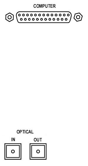
The Computer Connector
On the back panel of the Gina24 audio interface box is a connector labeled COMPUTER. It is the point at which the audio interface connects to the Gina24 PCI card inside your computer.
A cable was supplied with your Gina24 for this purpose. This custom made cable is manufactured to certain specifications and, if necessary, should only be replaced by a special Gina24 cable available only from Echo.
Please Note: The Gina24 cable is NOT interchangeable with Darla24 or Gina (20-bit) cables.
ADAT/S/PDIF optical I/O
Next to the COMPUTER connector is a pair of connectors labeled OPTICAL, IN and OUT. These connectors are used to transmit digital data among digital audio devices via an optical signal.
You can use this port for ADAT (8 channels) or for optical S/PDIF (stereo) I/O. NOTE: Gina24 is only capable of transmitting or receiving one type of digital signal at a time. You must choose either ADAT optical or S/PDIF (optical or RCA); you cannot use both simultaneously. The Digital Mode Switch can be found in the Gina24 Echo Console. For more information, see the appropriate section in this manual under the heading “The Echo Console.”
12

S/PDIF
Next to the ADAT connectors is a pair of connectors labeled S/PDIF, IN and OUT. These S/PDIF connectors are used to transmit digital data among digital audio devices via an electrical signal. S/PDIF data can use the full 24-bit sample width used internally on Gina24.
When connecting devices to the S/PDIF jacks on Gina24, the use of standard analog RCA audio cables is not recommended. For reliable S/PDIF operation, 75ohm coaxial (RG59) video cables are recommended.
13
Installing the Gina24 Software Drivers
Now that you have completed the hardware installation, you need to install the software drivers that allow Gina24 to interact properly with Windows 95/98 and your audio recording application.
Turn on the power to your computer’s CPU. After Windows 95/98 starts up, it will automatically sense the newly installed Gina24 card and indicate, via a pop-up Install Wizard window, that new hardware has been found. At this point, you should insert the Gina24 CD-ROM disc.
If you are using the original version of Windows 95:
Within the Install Wizard window are several options. Select the option
Driver from disk provided by hardware manufacturer. The computer will now prompt you for the location of the driver files. These files are located in the root directory of the Gina24 CD-ROM. Click the Browse button in the Install Wizard; this will cause the “Install From Disk” window to appear. In the field labeled “Copy manufacturer’s files from:”, enter the path D:\ (depending on your system configuration, your CD-ROM drive may use a letter other than “D”). Click on OK to complete the installation. Now skip over the next two paragraphs.
If you are using Windows 95 OSR2:
After you have inserted the Gina24 CD-ROM disc and clicked next, you’ll see the message, “Windows found the following updated driver for this device, Gina24 by Echo.” Click on the Finish button and Windows will attempt to locate the drivers on a disk labeled “Echo Install Disk.” This is caused by a bug in Windows 95 OSR2. So what you’ll see is a not-so-nice error message marked with a big red X. Ignore Windows’ rude behavior and click on the OK button. This will bring you to the Copying Files . . .
window. Within the window is a field labeled Copy Files From: into which you’ll need to enter the path name for the Gina24 drivers. Type in the letter name of your CD-ROM drive followed by :\ (for example, D:\). Click on OK, and Windows will complete the driver installation routine. Now skip over the next paragraph.
14
If you are using Windows 98:
After you have inserted the Gina24 CD-ROM disc and clicked next, you’ll see the message, “What do you want Windows to do?” Below that are two radio buttons. If it isn’t already selected, select the one labeled “Search for the best driver for your device (Recommended)”. Click on the Next button and a dialog will appear with several check boxes indicating places where Windows will look. Since you are installing from your CD-ROM drive, click on the appropriate box. Be sure all other boxes are unchecked. Click on the Next button and Windows will locate the drivers on the install disk and show you the Copying Files . . . window as it completes the driver installation.
15

After the drivers are installed, you should verify that Windows recognizes them. You can do this by checking in the Windows Control Panel as follows:
Begin by clicking on the Windows Start button. Then select Settings, followed by Control Panel. Now double-click on the icon labeled System. At the top of the System window, you will see a tab labeled Device Manager; click on the tab. Now locate the line labeled Sound, Video, and Game Controllers. Double-clicking on the “+” to the left of the line’s associated icon should reveal the line Gina24 by Echo; double-click on that line. If everything is in working order, a message should now appear on your screen that matches the picture below. In the center of the Gina24 Properties window will be a section called “Device Status.” Look for a message that reads: “This device is working properly.” If you see it, give yourself a hearty pat on the back for a job well done!
Proper installation of the Gina24 drivers will result in the message, “This device is working properly.”
16

If the message does not appear, check Appendices A, B and C for help in isolating the cause of your difficulties.
You can now exit back to the Control Panel window to check the Gina24 audio input and output devices that are available. In the Control Panel window, locate the Multimedia icon and double-click on it. This will bring the multimedia Properties window into view. Select the Audio tab to see a list of available playback and recording devices in the
Preferred Device fields.
You can view the Gina24 input and output devices in the Multimedia
Properties/Audio window.
17
Gina24 Audio Input & Output Devices
The Gina24 driver installs into your computer as a series of stereo .WAV devices. Pulling down the Preferred Device menu in the Control Panels/Multimedia/Audio Playback section will reveal the available Gina24 devices. You will be able to select from:
Gina24 1/2 Analog Playback
Gina24 3/4 Analog Playback
Gina24 5/6 Analog Playback
Gina24 7/8 Analog Playback
Gina24 S/PDIF Playback
Gina24 1/2 ADAT Playback
Gina24 3/4 ADAT Playback
Gina24 5/6 ADAT Playback
Gina24 7/8 ADAT Playback
In the Recording section, the following choices will be available:
Gina24 1/2 Analog Record
Gina24 S/PDIF Record
Gina24 1/2 ADAT Record
Gina24 3/4 ADAT Record
Gina24 5/6 ADAT Record
Gina24 7/8 ADAT Record
You’ll find these same input and output options available when using your audio record/editing software, with the devices assignable on a per-track basis. See your software owner’s manual for details on how to make these device assignments. Instructions for making these assignments in Cool Edit Pro Special Edition can be found in the special “Cool Edit Pro” section at the back of this manual.
NOTE: Although both S/PDIF and ADAT devices are listed and selectable, they are not simultaneously active. The Digital Mode Switch in the Echo Console determines which digital devices are currently active.
This completes the installation of the Gina24 hardware and software.
18

The Echo Console
Included with your Gina24 is a “virtual control surface” application called the Echo Console. Every time you start Windows you will see it flicker across the screen as it loads. Then it will minimize itself to the taskbar. The Console allows you to control the audio I/O and clocking functions of Gina24, and it brings these controls to a single easy-to-use location. From the console you can control the output levels, select synchronization clocks, select the digital mode, and adjust input monitoring.
The Echo Console software was automatically installed at the same time that you installed the Gina24 driver for Windows 95/98. If installation was successful, you should see a red capital letter G in your Windows 95/98 taskbar (typically in the bottom right-hand corner of your screen). Doubleclicking on the “G” will activate the console program. It should look like this:
19

The console functions are grouped into three areas: inputs (in the upper left corner), monitors (directly below the inputs that are being monitored), and outputs (on the right hand side). The controls for a particular function/stereo pair are then further grouped into a box that contains selection buttons, faders, and other controls and displays as determined by the function.
Console Controls
Let’s take a look at the control surface. The input control area is located in the upper left portion of the console surface. For each input device pair you will find a pair of input meters.
20
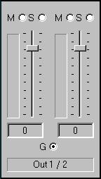
Monitor Controls
Below the input channels are the input monitor controls. The input monitor controls allow you to monitor the input signal via any of the available outputs on your Gina24. Each input channel pair has a corresponding monitor control pair directly below it on the console. At the top of each monitor pair are radio buttons that allow you to selectively mute (M) or solo
(S) each channel. In the middle you will find a pair of faders that will allow you to set the levels of the monitor signals. At the bottom of the control area there is a radio button that allows you to “gang” (G) the faders. Ganging the faders ties them together so that they will maintain their relative placement with regard to each other. Below each fader is its corresponding pan control. In the default pan positions (see example below) the signal from input 1(left) will be monitored by output 1(left), and the signal from input 2(right) will be monitored by output 2(right). Moving a pan control will determine how much of the input signal is sent to each output channel in the selected output pair. Both pan controls and faders can be reset to default by pressing the Ctrl button and left clicking on the control.
Instead of level meters, each monitor control has a series of numbered buttons. These buttons allow you to select which output channel pair controls are displayed, so you can adjust them.
The monitors are one of the most powerful functions of the console. When you are recording, these controls allow you to set the level at which each input signal will be monitored at each of the outputs, independent of the main output level control.
21
When setting a monitor level, you must first select the input that will be monitored, and then select the output for which you will set the monitor level. Selection of the input is really just a matter of using the correct monitor control box. A monitor setting will always affect the input pair that is directly above it. To set the monitor for inputs 1/2, for example, simply go to the monitor control directly below inputs 1/2 and click on one of the buttons found in the center of the control.
Let’s say you want to set the level at which input pair 1/2 is monitored for each of the four stereo analog output pairs on Gina24. You would first find the monitor control that corresponds to inputs 1/2 (the control on the far left, directly below the input control for channels 1/2). Clicking on the button within this box labeled “1” causes the control box to display the currently selected levels at which inputs 1/2 are being monitored at outputs 1/2. Clicking on the button labeled “3” would cause the control box to display the currently selected levels at which inputs 1/2 were being monitored at outputs 3/4. You can move through the remaining buttons, setting the level at which inputs 1/2 are monitored at each of the four output pairs, as well as the S/PDIF “D” and ADAT “A#” outputs. The console program remembers any settings that you make, and all settings for all outputs are maintained independently.
Note: You cannot monitor the S/PDIF inputs through the ADAT outputs and vice versa. This is because you can only use one digital mode (S/PDIF or ADAT) at any given time. For more information, please see the section “Digital Mode Switch” later in this manual.
Remember that all of the monitor controls remain in effect even when they’re not displayed. The degree of attenuation (or muting) of each level is set by the monitor controls. The console program constantly maintains a level setting for each of the monitor paths it controls. Clicking on an output selection button simply selects the settings that are displayed.
22
Output Controls
The right hand side of the console is dedicated to the controls for analog output channels one through eight (an output meter pair is included for the two S/PDIF output channels, but these levels are not adjustable). The output controls mirror those found on the monitor controls (Gang, Mute, Solo, & faders), except that there are no pan controls and you will find level meters in the middle area instead of the numbered buttons. Just like the monitor controls, the output faders can be reset to default by pressing the Ctrl button and left clicking on the fader.
Adjusting Record and Playback Levels
Gina24’s output volume adjustments are made in the digital domain. When you lower a volume slider, you are actually decreasing the number of available bits, thereby taking away from the potential dynamic range of the system. To avoid this, we suggest that whenever possible you leave the output sliders set to their maximum positions, and perform any necessary attenuation on your external mixer. When the Gina24 playback volume controls are set to maximum and the input signal approaches the maximum pre-clipping level, you can achieve the full 24-bit dynamic range of the system.
23
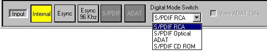
Setting Clock Sources and Destinations
At the very bottom of the Console there are buttons that allow you to select the synchronization clocks that are used by Gina24. The console program will detect which input clocking options are available, and automatically disable those that are unavailable. Depending on what external devices you have connected to Gina24, you may have as many as four options here.
Input clocks, Digital Mode Switch & View ADAT Ctrls are at the bottom of the Console.
If you are unsure which clock synchronization selections are appropriate for your installation, be sure to read the next section, which deals with the types of clocks that Gina24 supports.
Synchronizing Multiple Devices
Gina24 is designed to work alongside other audio equipment. If you are planning on using Gina24 with other audio equipment, please note the following:
The Gina24 Windows drivers included in this package support multiple Gina24s within the same system. In addition, your new Gina24 will operate alongside Mona, Layla, Layla24, Gina, Darla and Darla24. Gina24 can also peacefully coexist with audio equipment from other manufacturers, but be aware that operating alongside another product is not the same as operating with it. In order for accurate synchronization to occur, the other audio product(s) in your system must support a synchronization mode that is compatible with Gina24. Without such synchronization, the individual pieces of equipment will act independently of each other. This scenario may be fine for some musical applications; however, it is not appropriate for situations where sample-accurate synchronization is required.
24
Loading...