


8" - 9" chippers
71825s - 25 HP
71854s - 540 PTO
72825s - 25 HP w/hyd
72854s - 540 w/hyd
72928s - 28 HP w/hyd
Veiledning og Brukerhandbok |
Bruksavisning |
- Gebruiksen bizittershandleiding |
N - |
S - |
NL |
- Instruction & Owner's manual |
Manueld'instructions et du propietaire |
Anleitungs- & Betriebshandbuch |
GB |
F - |
D - |
MADE WITH PRIDE IN THE...
PN: 12136 R0498
Companion to 12151
owner's manual

Before You Begin
DEAR CRARY BEAR CAT CUSTOMER
Thank you for purchasing a Crary Bear Cat product. The Crary Bear Cat line is designed, tested, and manufactured to give years of dependable performance. To keep your machine operating at peak efficiency, it is necessary to adjust it correctly and make regular inspections. The following pages will assist you in the operation and maintenance of your machine. Please read and understand this manual before operating your machine.
If you have any questions or comments about this manual, please call us toll-free at 1-800-247-7335.
If you have any questions or problems with your machine, please call or write your local authorized Crary Bear Cat Dealer.
This document is based on information available at the time of its publication. Crary Bear Cat is continually making improvements and developing new equipment. In doing so, we reserve the right to make changes or add improvements to our product without obligation for equipment previously sold.
PLEASE SEND US YOUR WARRANTY CARD
A warranty card is included in your owner's kit packaged with your machine. Please take the time to fill in the information requested on the card. When you send your completed card to us, we will register your machine and start your coverage under our limited warranty.
PARTS ORDERING INFORMATION
For service assistance or parts, contact your nearest authorized Crary Bear Cat dealer or the factory. Your nearest authorized dealer will need to know the serial number of your machine to provide the most efficient service. See below for information on how to identify and record the serial number for your machine.
If you need engine service or parts:
For engine service pr parts, contact your nearest authorized engine dealer. An authorized engine dealer can handle all parts, repairs, and warranty service concerning the engine.
REPLACEMENT PARTS
Only genuine Crary Bear Cat replacement parts should be used to repair the machine. Replacement parts manufactured by others could present safety hazards, even though they may fit on this machine. Replacement parts are available from your Crary Bear Cat dealer.
Provide the following when ordering parts:
The SERIAL NUMBER of your machine. The PART NUMBER of the part.
The PART DESCRIPTION. The QUANTITY needed.
SERIAL NUMBER LOCATION
Please record the serial number in the space provided and on the warranty and registration card.
MANUFACTURED BY CRARY INDUSTRIES |
|
|
|
|
||
WEST FARGO, NORTH DAKOTA 58078 U.S.A. |
|
SERIAL NUMBER |
||||
SERIAL NUMBER XXXXXX |
|
|
||||
|
|
|
|
|
||
MANUFACTURED IN U.S.A. |
|
|
|
|
|
|
|
|
|
|
|
|
|
|
|
How to contact crary bear cat |
|
|
||
|
|
|
|
|
|
|
address |
|
Phone |
|
hours |
||
|
|
|
|
|
|
|
237 NW 12th Street |
|
800-247-7335 |
opesales@crary.com |
Monday - Friday, |
||
P.O. Box 849 |
|
701-282-5520 |
8 am to 5 pm |
|||
|
service@crary.com |
|||||
West Fargo, ND 58078 |
|
Fax: 701-282-9522 |
Central Time |
|||
|
|
|
||||
|
|
|
|
|
|
|
© 2006, Crary industries, all rights reserved. produced and printed in the u.s.a.

LIMITED WARRANTY
This warranty applies to Crary Bear Cat, Crary, Load-N-Lift, Lockwood and Weed Roller brand products manufactured by Crary Industries.
Crary Industries warrants to the original owner each new Crary Industries product to be free from defects in material and workmanship, under normal use and service. The warranty shall extend 1 year from date of delivery for income producing (commercial) applications and 2 years from date of delivery for non-income producing (consumer) use of the product. The product is warranted to the original owner as evidenced by a completed warranty registration on file at Crary Industries. Replacement parts are warranted for (90) days from date of installation.
The warranty registration must be completed and returned to Crary Industries within 10 days of delivery of the product to the original owner or the warranty will be void.
In the event of a failure, return the product, at your cost, along with proof of purchase to the selling Crary Industries dealer. Crary Industries will, at its option, repair or replace any parts found to be defective in material or workmanship. Warranty on any repairs will not extend beyond the product warranty. Repair or attempted repair by anyone other than a Crary Industries dealer as well as subsequent failure or damage that may occur as a result of that work will not be paid under this warranty. Crary Industries does not warrant replacement components not manufactured or sold by Crary Industries.
1.This warranty applies only to parts or components that are defective in material or workmanship.
2.This warranty does not cover normal wear items including but not limited to bearings, belts, pulleys, filters and chipper knives.
3.This warranty does not cover normal maintenance, service or adjustments.
4.This warranty does not cover depreciation or damage due to misuse, negligence, accident or improper maintenance.
5.This warranty does not cover damage due to improper setup, installation or adjustment.
6.This warranty does not cover damage due to unauthorized modifications of the product.
7.Engines are warranted by the respective engine manufacturer and are not covered by this warranty.
Crary Industries is not liable for any property damage, personal injury or death resulting from the unauthorized modification or alteration of a Crary product or from the owner’s failure to assemble, install, maintain or operate the product in accordance with the provisions of the Owner’s manual.
Crary Industries is not liable for indirect, incidental or consequential damages or injuries including but not limited to loss of crops, loss of profits, rental of substitute equipment or other commercial loss.
This warranty gives you specific legal rights. You may have other rights that may vary from area to area.
Crary Industries makes no warranties, representations or promises, expressed or implied as to the performance of its products other than those set forth in this warranty. Neither the dealer nor any other person has any authority to make any representations, warranties or promises on behalf of Crary Industries or to modify the terms or limitations of this warranty in any way. Crary Industries, at its discretion, may periodically offer limited, written enhancements to this warranty.
Crary Industries reserves the right to change the design and/or specifications of its products at any time without obligation to previous purchasers of its products.
Insert
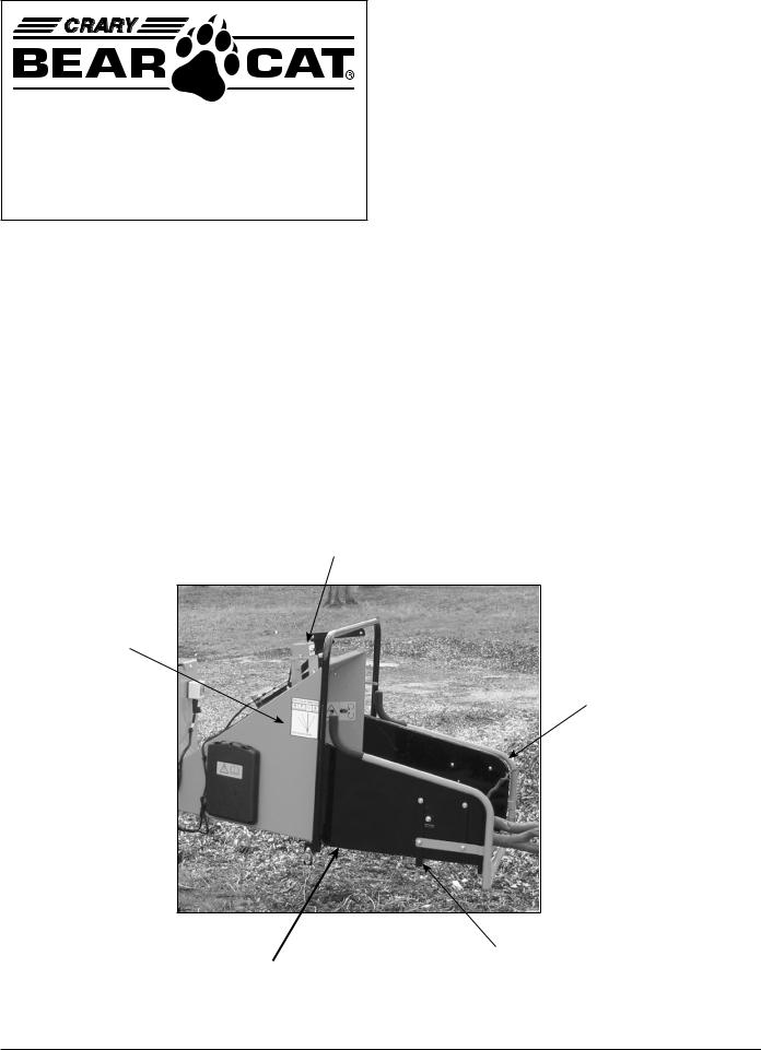
PRODUCT: BearCat 8" Chippers
SUBJECT: Safety Bar
The feed chute has an extension tray that extends out 29 inches. Around the edge of the tray is an orange comtrol arm that will contact a safety switch when depressed. The safety switch will close the solenoid valve, stopping the hydraulic flow to the feed roller drum. The chipper will not feed material until the reset button on the top of the feed chute is pressed.
The switch box has a red light that will indicate the switch has been triggered and will not go out until the reset button has been reset. The reset button will release the solenoid valve allowing the hydrauylic fluid to the feed roller drum.
RESET BUTTON
feed chute
CONTROL ARM
SAFETY SWITCH
EXTENSION TRAY
Rev 030205
Crary Bear Cat Insert
|
|
|
|
|
|
C O N T E N T S |
|
|
|
|
|||
Contents |
1.2 Safety Decals .................................................................................................... |
4 |
||||
|
|
Section1: SafetyInstructions ......................................................... |
2 |
|||
|
|
Section2: Assembly ........................................................................ |
6 |
|||
|
|
2.1. 25 HP Models .................................................................................................... |
6 |
|||
|
|
|
|
2.1.1 Attach the Chipper Chute ............................................................... |
6 |
|
|
|
|
|
2.1.2 Attach the Chute Extension Tray .................................................... |
6 |
|
|
|
|
|
2.1.3 Attach the Blower Discharge Tube ................................................ |
6 |
|
|
|
|
|
2.1.4 Before Using ................................................................................... |
6 |
|
|
|
2.2. 28 HP Models |
|
|||
|
|
|
|
2.2.1 |
Attach the Pintle Hitch ..................................................................... |
6 |
|
|
|
|
2.2.2 Attach the Chipper Chute ............................................................... |
7 |
|
|
|
|
|
2.2.3 Attach the Chute Extension Tray .................................................... |
7 |
|
|
|
|
|
2.2.4 Attach the Blower Discharge Tube ................................................ |
7 |
|
|
|
|
|
2.2.5 Before Using ................................................................................... |
7 |
|
|
|
2.3 PTO Models ........................................................................................................ |
7 |
|||
|
|
|
|
2.3.1 Attach the Chipper Chute ............................................................... |
7 |
|
|
|
|
|
2.3.2 Attach the Chute Extension Tray .................................................... |
8 |
|
|
|
|
|
2.3.3 Attach Blower Discharge Tube ...................................................... |
8 |
|
|
|
|
|
2.3.4 Connect the PTO Shaft ................................................................... |
8 |
|
|
|
|
|
2.3.5 Before Using ................................................................................... |
8 |
|
|
|
2.4 All Models |
........................................................................................................... |
8 |
||
|
|
|
|
2.4.1 ........................................ |
Connect the Hydrostatic Control Cable |
8 |
|
|
|
|
2.4.2 .............................................................................. |
Hydraulic Fluids |
8 |
|
|
|
|
2.4.3 ............................................................. |
Prepare Hydraulic System |
8 |
|
|
Section3: Controls ...........................................andIdentification |
10 |
|||
|
|
3.1. 25 HP Model ...................................................................................Controls |
10 |
|||
|
|
3.2. 25 HP Model ............................................................................Identification |
10 |
|||
|
|
3.3. 28 HP Model ............................................................................Identification |
10 |
|||
|
|
3.4 |
PTO Model .................................................................................Identification |
11 |
||
|
|
Section 4: Operation ..................................................................... |
12 |
|||
|
|
4.1 |
Starting 25 ......................................................................................HP Model |
12 |
||
|
|
4.2 |
Starting 28 ......................................................................................HP Model |
12 |
||
|
|
4.3 |
Starting PTO .........................................................................................Model |
13 |
||
|
|
4.4 |
|
Chipping .......................................................................................................... |
|
13 |
|
|
4.5 |
|
Stopping ......................................................................................Instructions |
14 |
|
|
|
Section 5: Service .............................................and Maintenance |
15 |
|||
|
|
5.1 |
|
Service and ...................................................Maintenance: Engine Models |
15 |
|
|
|
5.2 |
Service and .........................................................Maintenance: PTO Model |
16 |
||
|
|
5.3 |
|
Sharpening ..........................................................................Chipper Blades |
17 |
|
|
|
5.4 |
|
Chipping ..................................................................Blade Sharpening Tips |
17 |
|
|
|
5.5 |
|
Setting Chipping ................................................................Blade Clearance |
17 |
|
|
|
5.6 |
Adjusting .........................................................................................Drive Belt |
18 |
||
|
|
5.7 |
Replacing .......................................................................................Drive Belt |
18 |
||
|
|
5.8 |
|
Clearing Plugged .................................................................................Rotor |
18 |
|
|
|
5.9 |
|
Repairing .......................................................or Replacing Rotor Bearings |
18 |
|
|
|
5.10 |
Adjusting ..............................................the Hydraulic Feed Control Cable |
19 |
||
|
|
5.11 |
Greasable ..................................................................Bearings and Pivots |
19 |
||
|
|
5.12 |
Hydraulic .......................................................................Feed Maintenance |
20 |
||
|
|
5.13 Trailer Service .......................................................................................Tips |
20 |
|||
|
|
Section6:Troubleshooting ........................................................... |
21 |
|||
|
|
6.1 |
|
Troubleshooting .............................................................................................. |
21 |
|
|
|
6.2 |
|
Hydrostatic ..............................................................Pump Troubleshooting |
22 |
|
|
|
Section7: Optional .................................ElectronicFeedSensor |
23 |
|||
|
|
7.2 Operation .......................................................of the Electronic Feed Control |
23 |
|||
|
|
Section8: Specifications .............................................................. |
24 |
|||
|
|
Section9: Replacement ..........................andMaintenanceChart |
25 |
|||
|
|
Section10: Diagrams ..........................................andIllustrations |
26 |
|||
|
|
Warranty |
|
|
|
|
1

S E C T I O N 1
Safety Instructions
This chipper is designed and tested to offer reasonably safe service. However, failure to operate it in accordance with the follow-
ing safety instructions MAY RESULT IN PER-
SONAL INJURY!
Before Operating
1.Become familiar with the owner's manual before attempting to operate this equipment. See engine owner's manual for additional safety information.
2.Do not allow children to operate this equipment.
3.Do not operate this equipment in the vicinity of bystanders.
4.Carbon monoxide can be extremely dangerous in enclosed areas; do not run the machine in an enclosed area. The exhaust from the engine contains carbon monoxide, which is colorless, odorless, and tasteless.
5.Do not allow hands, or any part of body or clothing, inside the feeding chamber, discharge chute, or near any moving part.
6.Before inspecting or servicing any part of the machine, shut off the engine (disengage PTO), and make sure all moving parts have come to a complete stop.
Preparation
1.Obtain and wear safety glasses at all times while operating the machine. One pair of safety glasses is provided with each chipper.
2.Avoid wearing loose-fitting clothing. Never operate this machine wearing loose clothing particularly if it has drawstrings which could wrap around or get caught in the machine.
3.Operate the machine only on a level surface. Do not operate the machine on a paved, concrete, or hard gravel surface. Operating on a hard surface may cause discharged material to rebound and kickback. It will also cause increased machine vibration. Increased vibration may cause the machine to move and will promote premature wear of parts or loosening of fasteners.
4.Before starting the machine, visually check that
all screws, nuts, bolts, and other fasteners are properly secured. Once every 10 hours of operation, all screws, nuts, bolts, and other fasteners should be checked for proper tightness to insure everything is in proper working condition.
Operation
One of the critical moments in job safety, as well as chipper safety, is setting up your chipping site so you are not endangered by traffic and the public is not endangered by your work. Great care must be taken to provide adequate warning. Use signs and/or cones if it is necessary to divert vehicle or pedestrian traffic.
A well-prepared traffic plan should include parking off the highway whenever possible. The work area should be coned off as soon as the chipper vehicle is stopped. Avoid sudden traffic stops or lane changes. Do not allow pedestrians to walk through the work area. Make sure chips or dust do not blow into traffic, parked cars, or pedestrians.
1.Before starting the machine, make certain that the cutting chamber is empty.
2.When feeding chipable material into the machine, be extremely careful to exclude pieces of metal, rocks, bottles, cans, and other foreign objects.
3.If the cutting mechanism strikes any foreign object or if the machine should start making an unusual noise or vibration, immediately shut off the engine (or disengage PTO), and allow the machine to come to a complete stop. After machine stops:
a)Inspect for damage.
b)Replace or repair any damaged parts.
c)Check for and tighten any loose parts.
4.Every 10 hours of operation, check the bolts on the following for correct torque (75 ft. lbs.):
• Hydraulic feed roller bearing
• Hydraulic motor mounting
• Chipper rotor bearing
• Chipper blades
• Rotor paddles
• Chipper anvil
2

S E C T I O N 1
Failure to maintain proper fastening torque (75 ft. lbs.) on bolts for the components listed above may result in severe damage to the chipper and/ or personal injury!
5.Do not allow processed material to build up in the discharge area; this may prevent proper discharge and can result in kickback of material through the feed opening.
6.Do not attempt to operate the chipper with any of the guards, deflectors, or shrouds removed. Keep away from moving parts.
7.Keep all guards, deflectors, and shrouds in good working condition.
8.Always stand clear of the discharge area when operating this machine.
9.Keep your face and body away from the feed opening.
10.Do not overreach. Keep proper balance and footing at all times.
11.Do not transport or move machine while the machine is running.
12.If the machine becomes clogged, shut off engine (or disengage PTO). Allow machine to come to a complete stop before clearing debris.
Additional Safety Rules for Towing (Towable Models)
1.Before towing, rotate the discharge tube to face in the opposite direction of the vehicle that is towing it. This will prevent the discharge tube from projecting over the trailer wheels and striking foreign objects.
2.Always connect hitch safety chains. Make sure trailer hitch bolts are tight and secure. Do not attempt to attach the pintle hitch to a ball type vehicle hitch.
The Standard muffler installed on the  chipper engine does not include a spark arrestor. If this machine is to be used in an area where a spark arrestor is required by law, one will have to be added before use. Contact the local authorities to see if these laws apply to you. See your authorized engine dealer for spark arrestor options.
3.Maximum towing speed should not exceed 55 M.P.H. Inflate tires to manufactures specs. as stated on the tire sidewall. Check wheel lug bolts periodically to be sure they are tight and secure.
4.Make sure that the jack stand on trailer is in the UP position to clear the ground during towing. Place the jack stand on a level surface and secure it in the DOWN position before use.
5.Never allow passengers to ride on the infeed chute while the vehicle is moving (whether the chipper is running or not).
Additional Safety Rules for PTO Models
Warning: Keep body and clothing away from  PTO shaft when running.
1.Connect 3 pt. hitch pins and snap pins, connect PTO shaft, and have leg stands solidly on the ground when in use.
2.Before moving, allow machine to come to a complete stop. To move unit: shut off PTO, and lift 3 pt. hitch.
3.Always disengage tractor PTO and shut off engine before removing guards or shields.
4.Keep hands, feet, and clothing away from all PTO drive parts. Keep guards and shields in place at all times while operating.
5.Before starting tractor, always make sure transmission is in neutral or park and PTO is disengaged.
Warning: This chipper is designed to be used with tractor PTO's rated at 20 to 60 horse-
power. Using this chipper with PTO's above 60 horsepower may cause belt and machine damage in overload conditions.
Maintenance and Storage
1.On engine models, make sure that the key is removed from key switch. Disconnect battery. On PTO models, disconnect PTO.
2.Store the machine out of the reach of children and where fuel vapors will not reach an open flame or spark. For storage periods of three months or more, drain the fuel and dispose of it in a safe manner (engine models). Always allow the machine to cool before storing.
3

S E C T I O N 1
1.2 Safety Decals
Safety and instruction decals are located on the chipper frame and engine. Replace any decal that is damaged or unreadable. Call dealer for information on decals in Spanish, French, or other languages.
NOTE: For engine safety and instruction decals, see engine owner's manual or contact the engine manufacturer.
12250 |
12183 |
|
|
||
|
|
|
Used on All Models: Check chipper blade, anvil and feed roller bolt for proper torque after every 10 hours of operation. Refer to Owner's Manual for instructions.
12174
Used on all Models: Keep hands and other body parts from rotating parts. Replace shields before operating machine.
12173
Used on All Models: Keep away from discharge opening while machine is operating. Point discharge away from bystanders or anything that could be damaged by flying debris.
Used on 25 and 28 HP Models: Press clutch pedal down with foot to disengage clutch while starting engine. Slowly release foot to engage chipper clutch after engine is running.
12172 |
1 |
2 |
3 |
4 |
5 |
6 |
12175
Used on All Models: Keep hands and feet out of inlet and discharge openings while machine is operating to avoid serious injury.
Usedon25and28HPModels:
Panel 1 - Attention
Panel 2 - Read and become familiar with the Owner's manual before operating this machine.
Panel 3 - Wear proper eye and ear protection while operating this machine.
Panel 4 -Stop machine and allow all parts to come to a complete stop before cleaning, making adjustments or servicing machine.
Panel 5 and 6 - Stop engine and remove spark plug wire or key before cleaning, making adjustments or servicing machine.
4

S E C T I O N 1
12169
Used on 28 HP and PTO Model: Keep hands and feet out of inlet and discharge openings while machine is operating to avoid injury.
12168
Used on PTO Model: Keep hands, feet and body away from driveshaft while machine is operating to avoid entanglement. Operate machine at a 540 PRM input speed.
5

S E C T I O N 2
Assembly
Your chipper may arrive totally or partially assembled. If your chipper arrives partially assembled, you may need to perform the steps in this section.
2.1. 25 HP Models
1.Remove the chipper from its shipping crate. Place the unit on a level surface before attempting to assemble it. Support the frame with wood blocks or other support device before installing axle. See the Torque Chart, page 7, for minimum tightening torque of bolts and screws.
2.Your chipper may be shipped without an axle. You must supply the required axle and install the axle, wheels, and tires according to the manufacturer's specifications.
3.Mount the trailer hitch to the frame using three 3/8 X 3-1/2" bolts and locknuts (supplied).
2.1.1 Attach the Chipper Chute
 Do not operate this unit without the chipper chute correctly installed. Rotating cutting
blades can cause serious personal injury.
Mount the chipper chute to the hydraulic feed using eight 3/8" x 1" bolts and locknuts. To insert the top bolts, you may need to temporarily lift the grab roller with a pry bar. Use three bolts on each side and two on the bottom (see figure 10.1).
2.1.2 Attach the Chute Extension Tray
1.After mounting the chute to the hydraulic feed, slide the chute extension tray over the chipper chute as shown in figure 10.2. Make sure that you position the lip on the extension tray behind the lip on the chipper chute. Align the five bolt holes in the chute extension tray with the bolt holes in the hinge.
2.Insert five 3/8" x 1" carriage bolts (included in owner's kit packaged with the chipper) through the tray and the extension hinge. Secure the bolts with washers and nuts. Secure with hairpin clips.
2.1.3 Attach the Blower Discharge
Tube
Attach the blower discharge tube to the mounting flange on the chipper frame (see figure 10.3). Half of the mounting clamp is already attached to the tube. Slide the tube into the flange and tighten the bolts to secure it. Install the second half of the clamp to the tube and flange. Rotate the tube 360 degrees and lock it in place with the handle to make sure it is mounted correctly.
2.1.4 Before Using
1.Install battery (not included: use group 22F 300 CCA min), connect positive and ground battery cables, and check battery condition. Charge if needed. Note: If needed, a larger group UB72 battery may be used.
 Use caution when connecting battery cables near fuel. A spark could ignite the fuel and
cause a fire.
2.Fill the engine with oil (per instructions in supplied engine manual) and fill the fuel tank with fuel.
Important! See instructions for hydrostatic pump start-up procedure, page 8.
2.2. 28 HP Models
1.Remove the chipper from its shipping crate. Place the unit on a level surface before attempting to assemble it. Support the frame with wood blocks or other support device before installing axle. See the Torque Chart, page 7, for minimum tightening torque of bolts and screws.
2.Your chipper may be shipped without an axle. You must supply the required axle and install the axle, wheels, and tires according to the manufacturer's specifications.
2.2.1. Attach the Pintle Hitch
1.Insert the adjustable hitch into the hitch opening in the chipper trailer. Insert a 3/8" x 2" bolt through the bolt hole in the adjustable hitch as shown in figure 10.4. Place the end link in the
6
S E C T I O N 2
safety chain welded to the chipper trailer over the 3/8" bolt end. Secure the chain with a washer and nut.
2.Attach the pintle hitch eye to the adjustable hitch with 5/8" x 2" bolts, washers, and nuts. Torque the bolts to 90 ft. lbs.
3.Connect the safety chains to the adjustable hitch weldment as shown in figure 10.4. Use a 3/8" x 2-1/2" bolt, washers, and nut to attach the two safety chains with hooks as shown.
4.Push the top link pin through the holes in the hitch and trailer. Secure the top link pin with a lynch pin.
Adjust the hitch to make the chipper trailer as level as possible when connected to the towing vehicle.
2.2.2 Attach the Chipper Chute
 Do not operate this unit without the chipper chute correctly installed. Rotating cutting
blades can cause serious personal injury.
Mount the chipper chute to the hydraulic feed using eight 3/8" x 1" bolts and locknuts. To insert the top bolts, you may need to temporarily lift the grab roller with a pry bar. Use three bolts on each side and two on the bottom (see figure 10.1).
2.2.3 Attach the Chute Extension Tray
1.After mounting the chute to the hydraulic feed, slide the chute extension tray over the chipper chute as shown in figure 10.2. Make sure that you position the lip on the extension tray behind the lip on the chipper chute. Align the five bolt holes in the chute extension tray with the bolt holes in the hinge.
2.Insert five 3/8" x 1" carriage bolts (included in owner's kit packaged with the chipper) through the tray and the extension hinge. Secure the bolts with washers and nuts. Secure with hairpin clips.
2.2.4 Attach the Blower Discharge
Tube
Attach the blower discharge tube to the mounting flange on the chipper frame (see figure10.3). Half of the mounting clamp is already attached to the tube.
Slide the tube into the flange and tighten the bolts to secure it. Install the second half of the clamp to the tube and flange. Rotate the tube 360 degrees and lock it in place with the handle to make sure it is mounted correctly.
2.2.5 Before Using
1.Install battery (not included: use group 22F 300 CCA min), connect positive and ground battery cables, and check battery condition. Charge if needed. Note: If needed, a larger group UB72 battery may be used.
Use caution when connecting battery cables near fuel. A spark could ignite the fuel and cause a fire.
2.Fill the engine with oil (per instructions in supplied engine manual) and fill the fuel tank with fuel.
Important! See instructions for hydrostatic pump start-up procedure, page 8.
2.3 PTO Model
2.3.1 Attach the Chipper Chute
Do not operate this unit without the chipper chute correctly installed. Rotating cutting
blades can cause serious personal injury.
1.Remove chipper from shipping crate. Place unit on a level surface before attempting to assemble. See Torque Chart for minimum tightening torque.
Torque Chart
Standard minimum tightening torque for normal assembly applications.
Bolts (SAE GR5)
Size Ft.Lbs.
5/16" 20 3/8" 35 1/2" 75 5/8" 90
Screws
Size Ft.Lbs.
5/16"Set 15
7

S E C T I O N 2
2.Mount the chipper chute to the hydraulic feed using eight 3/8" x 1" bolts and locknuts. To insert the top bolts, you may need to temporarily lift the grab roller with a pry bar. Use three bolts on each side and two on the bottom (see figure 10.1).
2.3.2 Attach Chute Extension Tray
1.After mounting the chute to the chipper frame, slide the chute extension tray over the chipper chute as shown in figure 10.2. Make sure that you position the lip on the extension tray behind the lip on the chipper chute. Align the five bolt holes in the chute extension tray with the bolt holes in the hinge.
2.Insert five 3/8" x 1" carriage bolts (included in owner's kit packaged with the chipper) through the tray and the extension hinge. Secure the bolts with washers and nuts. Secure with hairpin clips.
2.3.3 Attach Blower Discharge Tube
1.Attach the blower discharge tube to the mounting flange on the chipper frame (see figure 10.3). Half of the mounting clamp is already attached to the tube. Slide the tube into the flange and tighten the bolts to secure it. Install the second half of the clamp to the tube and flange. Rotate the tube 360 degrees and lock it in place with the handle to make sure it is mounted correctly.
2.3.4 Connect the PTO Shaft
1.Connect the PTO Shaft female end to the rotor shaft using key stock and two set screws contained in the owner's kit.
2.Connect the opposite end of the PTO shaft to the tractor.
2.3.5 Before using
Check all screws, bolts and nuts for tightness. See torque chart on page pg 7 for proper tightening torque.
Important! See instructions for hydrostatic pump start-up procedure, at right.
2.4 All Models
2.4.1 Connect the Hydrostatic Control
Cable
1.Remove the clevis assembly from the hydrostatic control cable end (see figure 10.5). Remove one nut on the cable end. Insert the cable end into the hole in the cable anchor weldment. Replace the nut and the clevis assembly.
2.Attach the clevis assembly to the center hole on the feed control lever.
3.Adjust the cable detent ball to hold the control arm is in the forward position or neutral position detents.
Important! See section below for hydrostatic pump start-up procedure
2.4.2 Hydraulic Fluids
Handle pressurized hydraulic fluid carefully. Escaping pressurized hydraulic fluid can have sufficient force to penetrate your skin causing serious injury. This fluid may also be hot enough to burn. Serious infection or reactions can develop if proper medical treatment is not administered immediately.
Premium hydraulic fluids containing high quality rust, oxidation, and foam inhibitors are required. These include premium turbine oils, API CD engine oils per SAE J183, M2C33F or G automatic transmission fluids meeting Allison C-3 or Caterpillar TO-2, and certain specialty agricultural tractor fluids.
2.4.3 Prepare Hydraulic System
Follow this start-up procedure when starting a new installation or when restarting an installation in which the hydrostatic pump has been removed from the system.
The flow from the reservoir to the hydrostatic pump and the flow returning from the hydrostatic pump are always the same. Hydraulic fluid can flow either direction between the hydrostatic pump, crossover relief valve, and motor. Refer to page 10.6 for the hydraulic Schematic.
8

S E C T I O N 2
1.Before starting the hydrostatic pump, make sure all system components (reservoir, fittings, etc.) are clean.
2.Fill the reservoir with recommended hydraulic fluid, which should be filtered before entering the reservoir.
3.The inlet line leading from the reservoir to the charge pump must be filled before start-up. Loosen the fitting at the pump on this inlet line until oil bleeds out.
 Warning! Do not start engine unless pump is in neutral or detent position on the cable.
4.Start the engine and run at the lowest possible RPM.
5.Loosen the motor fittings until oil bleeds out to remove air from the system. Retighten fittings.
6.As air is purged from the unit, the oil level in the reservoir will drop and bubbles may appear in the fluid. Refill the reservoir as necessary.
7.Run the feed roller in both directions for several minutes until any remaining air is purged from the unit. Refill the reservoir as necessary.
8.Shut down the engine, (or disengage PTO) check for and correct any fluid leaks, and check the reservoir level. Add fluid if necessary. The hydrostatic pump is now ready for operation.
Hydrostatic pressure controlled by the crossover relief valve is factory set at 1750 PSI. A 2000 PSI shim kit is available for extreme conditions.
9

S E C T I O N 3
Controls and
Identification
3.1. 25 HP Model Controls
1.Engine Throttle Lever: See figure 10.7. Changes engine speed. Turn knob clockwise for full throttle operation. Turn knob counterclockwise for idle on warm up. Turn knob fully counterclockwise to shut engine off. Refer to engine manual for further engine operating instructions.
2.Engine Choke: Use when starting cold engine. Pull to ON position when starting. Push lever to OFF position when engine is running. Refer to engine manual for further engine operating instructions.
3.Key Switch: (located to the right of the throttle lever) Turn clockwise to start engine. Release as soon as engine is running. Do not crank starter for more than 10 seconds of damage could result.
4.Other Engine Components: See Figure 10.8.
3.2. 25 HP Model
Identification (see figure 10.9)
1.Engine Fuel Tank: Use unleaded fuel; do not mix with oil.
2.Trailer Hitch: Always use 2 inch ball and safety chains.
3.Jack Stand: Always have in UP position and clear from ground when moving. When in use, place in DOWN position on a level surface.
4.Engine Drive Belt and Shield: Never remove shields when in use.
5.Chipper Chute: Feed material to be chipped through the chute.
6.Engine Controls: See figure 10.7.
7.Rotor Access Cover: Open to remove chipper blades.
8.Engine Battery (not included)
9.Rotor Shaft End Cover: Covers rotor shaft and
bearing. Has lock assembly to lock in place while moving.
10.Clutch Foot Pedal: Used to engage rotor assembly drive belt.
11.Adjustable Chipping Block
12.Foot Pedal: Used to pivot machine 360 degrees.
3.3. 28 HP Model
Identification (see figure 10.10)
1.Extension Tray: Assists in feeding chipping material. Folds for towing.
2.Feed Control Lever: Move the arm forward to increase the feed rate. Push back to reverse the feed.
3.Chipper Chute: Feeds materials to the chipper blades for chipping.
4.Discharge Tube: Chipped material exits through this tube. Tube is adjustable 360 degrees.
5.Drive Belt Shield: Never remove shields when in use.
6.Control Panel: (figure 10.11) Contains the key switch, throttle control, gauges, indicator lights, and Murphy switch.
7.Fuel Tank: Fuel level indicator is located on top.
8.Pintle Hitch: Always use safety chains when towing chipper.
9.Pivoting Tongue Jack: Always have in UP position and clear from ground when moving. When in use, place in DOWN position on a level surface. Turn handle to raise or lower wheel.
10.Battery: (Not included.) Use group 22F 300 CCA min.
11.Clutch Foot Pedal: Used to engage rotor assembly drive belt.
10

S E C T I O N 3
3.4. PTO Model
Identification (see figure 10.12)
1.Three pt. Hitch Connection: Mounts chipper to tractor 3 pt. hitch. Connect direct for category 1.
2.PTO Shaft: Connects chipper to tractor PTO shaft. Avoid driveline angles over 20 degrees on PTO shaft when unit is in use.
3.Drive Belt Shield: Never remove shield while machine is running.
4.Chipper Chute: Feeds materials to the chipper blades for chipping.
5.Leg Stands: Never move machine unless 3 point is lifted and legs clear the ground.
6.Rotor Access Cover: Tilts up to remove chipper blades and to service rotor assembly.
7.Discharge Tube: Chipped materials will exit through this tube. Tube is adjustable 360 degrees.
8.Adjustable Chipping Anvil: Adjusts to vary the size of chips.
9.Rotor Shaft Bearing Cover: Rotor shaft has lock assembly to lock rotor in place while servicing.
NOTE: Minimum and maximum telescoping on the PTO shaft is 20-28 inches. This will leave 4 inches overlap at maximum telescoping distance (see figure 10.13).
 Caution: Wear safety glasses at all times when operating the machine. Do not wear loose
fitting clothing. The operator should always wear heavy boots, gloves, pants and shirt. Use common sense and practice safety to protect yourself from branches, sharp objects and other harmful objects.
Note: The heavy rotor will continue to turn for some time after the engine or tractor has been shut off. You can tell that the rotor has stopped when no noise or machine vibration is present. Inserting a branch into the chipper chute to contact the blades will slow the rotor and shorten stopping time.
11

S E C T I O N 4
Operation
4.1 Starting 25 HP Model
 Caution: Move machine to a clear, level area outdoors before starting. Do not operate
machine on a paved, concrete, or gravel surface. Do not operate in the vicinity of bystanders. Make sure cutting chamber is empty before starting.
1.Before starting, fill engine with oil to the correct level. See engine manual for engine operation and maintenance instructions.
Note: Some oil usage is normal. Check level with each use.
Warning: Handle fuel (gasoline) with care. It is highly flammable. Always use an approved container and fill tank outdoors. Never add fuel to a
running or hot engine.
2.Before starting, fill fuel tank with fresh, clean unleaded regular gasoline. DO NOT MIX OIL WITH GASOLINE.
3.Place the throttle control midway between slow and fast positions. Place the choke control to the ON position.
 Caution: See operation/start-up decal by foot clutch pedal on machine before starting.
4.Depress foot clutch pedal to disengage drive belts and enable engine to start.
5.Activate the starter switch. Release the switch as soon as the engine starts. Do not crank engine for more than 10 seconds.
6.Move choke lever to RUN position. After a short shut down, full choke may not be necessary. If engine fails to start, move lever to RUN or partial choke.
7.Once engine is running and no choke is needed, slowly let foot clutch pedal up. This will engage drive belt and the rotor will turn.
8.If engine kills when engaging foot clutch pedal, either use more choke or increase engine RPM.
9.When clutch is engaged, the foot pedal may vibrate or shake until the engine and rotor have increased to full running RPM.
10.The chipper frame assembly can turn 360 degrees clockwise or counterclockwise. Press down on the foot pedal located underneath the frame near the tow hitch and the frame will pivot on the trailer to your desired location. Let up on the foot pedal and the frame will lock into place for use. The discharge tube can also turn 360 degrees to your desired location.
Warning: Return table to towing position and lock in place before moving machine. Do not
move chipper while machine is operating.
 Caution: Wear safety glasses at all times when operating the machine. Do not wear
loose fitting clothing. Protect yourself from branches, sharp objects, and other harmful objects with proper eye protection and clothing.
Warning: Do not leave machine unattended or attempt any inspection or service unless the
engine is stopped and the spark plug wire is removed from the spark plug.
4.2 Starting 28 HP Model
Caution: Move machine to a clear, level area outdoors before starting. Do not operate
machine on a paved, concrete, or gravel surface. Do not operate in the vicinity of bystanders. Make sure cutting chamber is empty before starting.
1.Before starting, fill engine with oil to the correct level. See engine manual for additional starting, operation, and maintenance instructions.
NOTE: Some oil usage is normal. Check level with each use.
 Warning: Handle fuel with care. It is highly flammable. Always use an approved container
and fill tank outdoors.
2.Before starting, fill fuel tank with fresh, clean diesel fuel. For instructions on bleeding the fuel system on initial start up or if fuel runs out, see engine manual.
 Caution: See operation/start-up decal by foot clutch pedal on machine before starting.
3.Turn key switch to preheat position. Hold in preheat position for several seconds until glow plug indicator light switches off.
12

S E C T I O N 4
4.Push throttle control in until it stops.
5.Depress foot clutch pedal, this will disengage drive belt and enable engine to start.
6.Push in and hold Murphy switch push-button. Continue to hold Murphy switch in when cranking engine until engine is running.
7.Activate the starter switch. Release the switch as soon as the engine starts. Do not crank over for more than 10 seconds. Release Murphy switch after engine is running; hold murphy switch in longer if engine immediately kills after releasing.
Note: The Murphy switch system will shut the engine off if the oil pressure is too low or if the engine temperature is too high. If the engine will not run or shuts of for these reasons, consult your local dealer.
8.Push center throttle control button in. Increase throttle control to full throttle. Turn throttle control knob clockwise to achieve maximum RPM.
9.Slowly let foot clutch pedal up. This will engage drive belt and the rotor will turn. If the engine kills when engaging the drive belt, release foot clutch pedal more slowly.
10.When clutch is engaged, the foot pedal may vibrate or shake until the engine and rotor have increased to full running RPM (3000 RPM).
 Caution: Wear safety glasses at all times when operating the machine. Do not wear
loose fitting clothing. Protect yourself from branches, sharp objects, and other harmful objects with proper eye protection and clothing.
 Warning: Do not leave machine unattended or attempt any inspection or service unless the
engine is stopped and the key switch is in OFF position. Do not move chipper during operation.
4.3 Starting PTO Model
Warning: This chipper is designed to be used with tractor PTO's rated at 20 to 60 horse-
power. Using this chipper with PTO's above 60 horsepower may cause belt and machine damage in overload conditions.
1.Place tractor transmission in park or neutral and set parking brake. Connect 3 pt. mounts between
the chipper and tractor. Secure connections with snap pins. Adjust 3 pt. top link so that chipper sits level.
2.Connect PTO shaft to tractor. Make sure you are using the correct RPM machine. Do not operate machine at speeds different than specified on shield.
3.Never inspect or work on PTO drive area without first disengaging PTO and shutting off tractor engine.
4.Start tractor engine and engage PTO drive clutch (see tractor owner's manual). Increase engine speed to rated PTO RPM position.
 Caution: Wear safety glasses at all times when operating the machine. Do not wear
loose fitting clothing. Protect yourself from branches, sharp objects, and other harmful objects with proper eye protection and clothing.
 Warning: Do not leave machine unattended or attempt any inspection or service unless
PTO is disengaged and the tractor engine is stopped. Do not move chipper during operation.
4.4 Chipping
 Warning: Keep face and body away from the feed opening. Do not over reach. Keep
proper balance and footing at all times.
The chipper is designed to chip a variety of materials into a more readily decomposing or handled condition. The following guidelines can be used to help you get started. Please read and follow all safety instructions in this manual. Failure to operate the chipper in accordance with the safety instructions MAY RESULT IN PERSONAL INJURY!
1.Be sure the unit is at full operating speed before you start to chip material.
2.Select limbs that are up to 8 inches in diameter for 25 HP model. The 28 HP and PTO models will chip limbs up to 9 inches in diameter. Trim side branches that cannot be bent enough to feed into the chipper chute. Small diameter branches can be held together in a bundle and fed in simultaneously.
13

S E C T I O N 4
3.Feed brush from the side of the infeed chute, rather than from the front. Then, step aside to avoid being hit by the brush moving into the chipper.
4.Never lean over the infeed chute to push objects into the cutting device. Use a push stick or brush paddle.
5.Never use shovels or forks to push brush. They can go through the chipper, are expensive to replace, and cause major damage. In addition, metal pieces can come back like shrapnel to injure or kill.
6.Never push brush into the infeed chute with your feet.
7.Engage the hydraulic feed by moving the control arm. Pull the arm toward you to engage the hydraulic feed (see figure 10.14). In the forward direction, the feed rate increases as the arm is moved.
8.Place limb, butt end first, into the chipper chute until it contacts the hydraulic feed roller and is drawn into the chipper blades. The actual feed rate of the limb into the chipper will depend on the type of material fed, and sharpness of the cutting blades.
If the engine slows to where it may stall, push the control lever inwards to slow or stop the material feeding and allow the engine to recover. Pull the lever out to restart feeding when the engine is back to full speed.
9.If the chipper jams, reverse the feed by moving the control arm in the reverse direction. Remove the branch and rotate it before reinserting it into the chute.
Alternately insert and retract the limb or insert continuously at a rate that will not kill the engine.
Chipping dead, dry material will create heat and dull the chipping blades quickly. Alternate greener material with dry material to lubricate the chipping blades for longer life and better performance. When the chipping blades become dull, they will require periodic sharpening. Refer to Service and Maintenance, "Sharpening Chipper Blades," page 17.
Note: The chipping blades will dull with use and will require periodic sharpening. Refer to page 17, "Sharpening Chipper Blades" for instructions.
4.5 Stopping Instructions:
Warning: Do not attempt any inspection or service until machine comes to a complete
stop. To stop machine, proceed as follows:
Engine Models:
1.Move engine throttle to slowest position.
2.Depress foot clutch pedal.
3.Turn key switch to off position.
4.Allow machine to come to a complete stop. Release the foot clutch pedal to help slow the rotor once the engine has stopped running.
PTO Models:
1.Move tractor throttle to SLOW position.
2.Disengage PTO lever and shut off tractor engine.
3.Allow machine to come to a complete stop.
Note: The heavy rotor will continue to turn for some time after the engine. You can tell that the rotor has stopped when no noise or machine vibration is present.
14

S E C T I O N 5
5.1 Service and Maintenance:
Engine Models
|
|
|
|
|
Interval |
|
|
|
|
Inspection Items |
Before |
Every |
Every |
Every |
Every |
Every |
Every |
Every |
Every |
|
Each |
10 |
25 |
50 |
100 |
200 |
400 |
800 |
1 |
|
Use |
Hours |
Hours |
Hours |
Hours |
Hours |
Hours |
Hours |
years |
|
|
|
|
|
|
|
|
|
|
Check Nuts & Bolts |
|
|
|
|
|
|
|
|
|
|
|
|
|
|
|
|
|
|
|
Engine Oil Level |
|
|
|
|
|
|
|
|
|
|
|
|
|
|
|
|
|
|
|
Change Engine Oil |
|
|
|
|
|
|
|
|
|
|
|
|
|
|
|
|
|
|
|
Replace Oil Filter Cartridge |
|
|
|
|
|
|
|
|
|
|
|
|
|
|
|
|
|
|
|
Check Hydraulic Fluid Level |
|
|
|
|
|
|
|
|
|
(3 Gallons) |
|
|
|
|
|
|
|
|
|
|
|
|
|
|
|
|
|
|
|
Replace Air Filter Element |
|
|
|
|
|
|
|
|
|
|
|
|
|
|
|
|
|
|
|
Replace Fuel Filter |
|
|
|
|
|
|
|
|
|
|
|
|
|
|
|
|
|
|
|
Check Sharpness of Chipper Blades |
|
|
|
|
|
|
|
|
|
|
|
|
|
|
|
|
|
|
|
Grease Bearings and Pivots |
|
|
|
|
|
|
|
|
|
|
|
|
|
|
|
|
|
|
|
Check Bolts: Chipper Blade, Feed |
|
|
|
|
|
|
|
|
|
Roller, Chipper Anvil, Rotor Paddles |
|
|
|
|
|
|
|
|
|
|
|
|
|
|
|
|
|
|
|
Check Drive Belt |
|
|
|
|
|
|
|
|
|
|
|
|
|
|
|
|
|
|
|
Hydraulic Control Cable |
|
|
|
|
|
|
|
|
|
(Feed Roller) |
|
|
|
|
|
|
|
|
|
|
|
|
|
|
|
|
|
|
|
Check Water Level |
|
|
|
|
|
|
|
|
|
|
|
|
|
|
|
|
|
|
|
Clean Machine |
|
|
|
|
|
|
|
|
|
Indicates first hours of use.
15

S E C T I O N 5
5.2 Service and Maintenance:
PTO Model
|
|
|
|
|
Interval |
|
|
|
|
Inspection Items |
Before |
Every |
Every |
Every |
Every |
Every |
Every |
Every |
Every |
|
Each |
10 |
25 |
50 |
100 |
200 |
300 |
800 |
1 |
|
Use |
Hours |
Hours |
Hours |
Hours |
Hours |
Hours |
Hours |
years |
Check Nuts & Bolts (entire machine)
Check
Replace
|
Check |
|
|
|
|
Hydraulic Filter Element |
Clean |
* |
|
||
|
|
|
|
Replace |
|
|
|
|
Check Hydraulic Control Cable |
|
|
|
|
|
Check Sharpness of Chipper Blades |
|
|
|
|
|
Grease Bearings and Pivots |
|
|
|
|
|
Check Bolts: Chipper Blade, Chipper |
|
|
Anvil, Rotor Paddles |
|
|
|
|
|
Check Drive Belt |
|
|
|
|
|
Clean Machine |
|
|
|
|
|
Note: (*) Service more frequently when used in dusty conditions |
|
|
Before inspecting or repairing any part of the machine, shut off the engine and make sure all
moving parts have come to a complete stop.
Indicates first hours of use.
16
S E C T I O N 5
Service and
Maintenance
 Warning: Before inspecting or servicing any part of the machine, shut off the engine, and
make sure all moving parts have come to a complete stop. The chipping blades are sharp! Use care when working on machine to avoid injury.
 Warning: The rotor assembly has a lock mechanism. When working on the rotor
assembly, use the lock mechanism at all times. Remove the plastic bearing cover beside the chipper chute. There is a hole in the rotor shaft and a matching hole in the bracket mounted to the rotor bearing front side. Install a punch through the rotor shaft and bracket to lock the rotor in place.
On engine models, check the engine oil, and change the oil and filter as recommended in the manual. Service and replace the air cleaner as recommended.
5.3 Sharpening Chipper Blades
The chipper blades will eventually become dull, making chipping difficult. It is recommended that the chipper blades are sharpened every 5-15 hours of chipper operation. To remove the chipping blades for sharpening:
1.Remove the two 3/8 inch retaining bolts holding access cover to main frame assembly.
2.Tilt access cover over to allow rotor access. Rotate the rotor so that the bolts holding a chipping blade are most accessible.
3.Remove the two allen head bolts holding the blade itself. Repeat for all four blades. The four chipping blades have two edges per blade and can be reversed one time each before sharpening. If both sides have not been used, remove and reverse the chipping blades. Reinstall chipping blades and proceed with chipping.
To grind the angled edge of the chipping blade to 45 degrees (see figure 10.15): Grind the blades on a slow-speed wet grinder if possible, or have them sharpened by a professional. If you use a bench grinder, be careful when grinding so that the blade material does not get too hot and change color–this will remove the blade's special heat treated
properties. Use short grinding times and cool with water. Try to remove an equal amount off each blade to maintain balance. Replace the chipping blades and tighten bolts to 75 ft. lbs. Close cover and replace bolts.
5.4 Chipping Blade Sharpening Tips
Poor chipping performance is usually a result of dull chipping blades. If your chipper's performance has decreased, check for the following symptoms:
•Severe vibration when feeding material into the chipper.
•Small diameter branches do not self-feed.
•Chips discharge unevenly or have stringy tails– especially when chipping green branches.
Before you sharpen the chipping blades, check for permanent damage. Replace the blade if:
•The blade is cracked (especially around the bolt holes) or the edges are too deeply chipped to be ground smooth.
•The base of the cutting edge is worn or has been re-sharpened so that it is too close to the rotor chipping slot.
5.5 Setting Chipping Blade Clearance
The four chipping blades should clear the chipper anvil located directly under the chipper chute by 1/16 inch to 1/8 inch. The chipper anvil is adjustable and reversible.
To adjust:
1.Lift rotor access cover and expose rotor (see figure 10.16). Loosen the three 1/2 inch bolts that hold the chipper anvil to the frame (see figure 10.17).
2.Measure the amount of clearance between chipping blade and chipper anvil from inside of housing.
3.Adjust inward or outward to desired measurement.
4.Tighten bolts on chipping block to 75 ft. lbs. and resume operation.
If chipper anvil edge is damaged or worn unevenly, remove the three bolts holding the anvil and use one
17

S E C T I O N 5
of the other three edges. Adjust for correct measurement.
5.6 Adjusting Drive Belt
Check the condition of the drive belt annually or after every 25 hours of operation, whichever comes first. If the belt is cracked, frayed, worn, or stretched, replace it. Only replace belt with original banded type belt, do not use single type belts. To adjust the belt, proceed as follows:
1.Engine Models: Depress foot clutch pedal. Shut engine off, and disconnect battery cables.
PTO Model: Disengage PTO and shut off tractor engine. Remove PTO shaft from tractor; disconnect machine from 3 pt. hitch. Remove round shield connected to belt guard that covers PTO shaft by removing two 5/16" nuts. Remove PTO shaft from chipper by removing two set screws and pulling shaft off.
2.Remove large belt guard (three 5/16 inch bolts).
3.Adjust the eyebolt that anchors the idler spring to adjust the belt tension. Tighten the eyebolt until the belt deflection at the center of the belt is 7/16" when a 20 lb. load is placed against the belt (see figure 10.18).
4.Replace belt guard.
5.Test machine for belt looseness. Replace the belt if no adjustment is left.
5.7 Replacing Drive Belt
1.Remove large belt guard (three 5/16" bolts).
2.Loosen bolts on hydraulic pump and remove belt.
3.Lift belt idler pulley off drive belt and remove drive belt from pulleys.
4.Install new belt on pulleys and lower belt idler. Check alignment of pulleys and adjust if needed.
5.Check belt tension before start-up. Adjust the eyebolt that anchors the idler spring to adjust the belt tension. Tighten the eyebolt until the belt deflection at the center of the belt is 7/16" when a 20 lb. load is placed against the belt (see figure 10.18).
6.Replace hydraulic pump belt. Readjust hydraulic pump belt tension by sliding the hydraulic pump in the mounting slots. Tighten bolts.
7.Replace belt guard.
8.Test the machine. Readjust pulleys and belt tension if needed.
5.8 Clearing Plugged Rotor
Warning: If the machine becomes plugged, depress foot clutch pedal, shut off the engine (or disengage PTO), and allow the machine to come
to a complete stop before clearing debris. Do not operate the machine without proper guards and screens in place.
Feeding too much chipable material at once may plug the chipper. To clear plugged rotor, proceed as follows:
1.Engine Models: Depress foot clutch pedal and stop engine. Release foot clutch pedal when engine is stopped.
PTO Model: Disengage PTO and shut off tractor engine.
2.Remove the two 3/8" retaining bolts holding the access cover to the main frame assembly.
3.Lift up rotor access cover.
4.Clean the debris out of the chipper rotor. Turn the rotor by hand to be sure it is free to rotate.
 Caution: Blades are sharp; avoid contact with chipper blades.
5.Close rotor access cover and replace bolts.
6.Engine Models: Depress foot clutch pedal, and start engine. Release foot clutch pedal when engine is running to engage drive belt. Resume operation.
PTO Model: Start tractor engine and engage PTO drive clutch. Increase engine speed to rated PTO RPM position.
5.9 Repairing or Replacing Rotor Bearings
1.Remove the two 3/8 inch retaining bolts holding access cover to main frame assembly. Tilt access cover over to allow rotor access.
18

S E C T I O N 5
2.Remove large belt guard (three 5/16 inch bolts).
3.Loosen bolts on hydraulic pump and remove hydraulic pump belt. Using the push bolts from the bushing, remove the bushing and pulley from the rotor shaft.
4.Lift belt idler pulley off drive belt and remove belt from pulleys. Using the push bolts from the bushing, remove the bushing and pulley from the rotor shaft.
 Warning: The rotor assembly has a lock mechanism. When working on the rotor
assembly, use the lock mechanism at all times. Remove plastic bearing cover under the chipper chute. There is a hole in the rotor jack shaft and a matching hole in the bracket mounted to the rotor bearing front side. Install a punch through the rotor shaft and bracket to lock the rotor in place.
5.Remove the four 1/2 inch bolts on each rotor bearing and remove the punch used to lock the rotor.
6.Using an overhead hoist or lifting device, lift the rotor assembly completely out of the frame. The complete rotor assembly is 275 lbs.
7.Once the rotor assembly is out of the frame, remove 3/8" bolts and collar from front. Remove both bearings with a puller and place new bearings on rotor shaft. Replace collar.
8.Use the overhead hoist or lifting device to return the complete rotor assembly to the chipper frame.
9.Slide rotor back until front collar is tight against the front bearing. Lock the front bearing and install the four 1/2 inch bolts on each bearing to secure them to the frame. Tighten bolts to 75 ft. lbs. Check and adjust chipper anvil if needed. Lock rear bearing.
10.Slide rear collar on shaft against rear bearing. Slide bushing onto shaft with flange against collar and lock bushing to shaft. Attach large pulley to bushing. Replace drive belt on pulleys and lower belt idler. Check alignment of pulleys and adjust engine if needed.
11.Check belt tension before start-up. Adjust the eyebolt that anchors the idler spring to adjust the belt tension. Tighten the eyebolt until the belt deflection at the center of the belt is 7/16" when
a 20 lb. load is placed against the belt (see figure 10.18).
12.Close cover and replace bolts.
13.Replace hydraulic pump bushing and pulley. Replace hydraulic pump belt. Readjust hydraulic pump belt tension by sliding the hydraulic pump in the mounting slots. Tighten bolts.
14.Replace belt guard and resume operation. Readjust pulleys and belt tension if needed.
5.10 Adjusting the Hydraulic Feed
Control Cable
Figure 10.19 shows the hydraulic feed control cable assembly and the detent position slots. The cable is attached and adjusted from the factory, but it should be checked and adjusted as needed before use. The hydraulic feed control lever has three positions:
Forward (lever moved toward the operator)
Neutral (lever in center position)
Reverse (lever moved away from operator; reverse has no detent position)
When the operator moves the control lever to the neutral position, the detent ball should be positioned in the rear detent slot (see figure 10.19). The feed roller should come to a complete stop when the control lever is in the neutral position. If it does not stop, adjust the clevis assembly on the control cable as follows:
1.If the control lever is in neutral and the roller creeps forward, the cable is too short; adjust it to a longer length.
2.If the roller creeps in a reverse direction, the cable is too long; adjust it to a shorter length.
3.Adjust the cable as needed to compensate for cable stretch.
5.11 Greaseable Bearings and Pivots
Engine Models: The engine model chippers have five greaseable bearings and pivots that require grease every 50 hours:
•Two bearings on the rotor shaft
•One greaseable bushing on the foot pedal pivot
19

S E C T I O N 5
•One grease zerk on idler pivot.
•One grease zerk on discharge chute.
Service engine according to engine manual. Change engine oil and filter as recommended in manual.
PTO Model: The PTO Model has ten greaseable bearings and pivots that require grease every 50 hours:
•Four grease zerks on the PTO shaft
•Two greaseable bearings on the rotor shaft
•Two greaseable bearings on the bottom jack shaft
•One idler arm pivot
•One on discharge chute
5.12 Hydraulic Feed Maintenance
Note: Check the reservoir daily for proper fluid level, the presence of water (noted by a cloudy to milky appearance, or free water in bottom of reservoir), and rancid fluid odor (excessive heat).
The hydrostatic pump normally does not require regular fluid changes. The system filter should be changed at 250 hour or annual intervals. The fluid and filter should be changed and system cleaned if the fluid becomes contaminated with foreign matter (water, dirt, grease, etc.) or if the fluid has been subjected to temperature levels greater than the maximum recommended.
There is a greaseable bearing on each side of the shaft on the hydraulic feed housing. Grease periodically.
5.13 Trailer Service Tips (Engine
Models Only)
1.Check wheel bolt torque every 10 hours of towing use.
2.Check air pressure in tires every 10 hours of towing.
3.Check and repack wheel bearings with grease every 12 months.
4.When towing, always connect the safety chains. Make sure trailer hitch bolts are tight and secure.
5.Check trailer lights.
20
|
|
|
|
|
|
S E C T I O N 6 |
6.1 Troubleshooting |
|
|
|
|||
Problem |
Probable Cause |
Suggested |
Reference |
|||
|
|
|
|
Remedies |
|
|
1. |
Rotor does not turn |
a) |
Obstructed |
a) |
Use branch or |
Service and Maintenance |
|
|
|
discharge |
|
similar object to |
|
|
|
b) |
Plugged rotor |
|
clear discharge |
|
|
|
|
|
b) |
Clear rotor |
|
2. Hard to feed chipper |
a) |
Obstructed |
a) |
Use branch or |
Service and Maintenance |
|
|
or excessive power |
|
discharge |
|
similar object to |
|
|
needed to chip |
b) |
Dull chipper blades |
|
clear discharge |
|
|
|
c) |
Improper blade |
b) |
Sharpen blades |
|
|
|
|
clearance |
c) |
Adjust clearance |
|
3. |
Chipper requires |
a) |
Obstructed |
a) |
Use branch or |
Service and Maintenance |
|
excessive power or |
|
discharge |
|
similar object to |
|
|
stalls |
b) |
Plugged rotor |
|
clear discharge |
|
|
|
c) |
Green material will |
b) |
Clear rotor, feed |
|
|
|
|
not discharge |
|
material into |
|
|
|
|
|
|
shredder more |
|
|
|
|
|
|
slowly |
|
|
|
|
|
c) |
Alternately feed dry |
|
|
|
|
|
|
material, or allow |
|
|
|
|
|
|
material to dry |
|
4. |
Drive belts |
a) |
Plugged rotor |
a) |
Clear rotor |
Service and Maintenance |
|
squealing or |
b) |
Loose or worn belts |
b) |
Adjust belt tension |
|
|
smoking |
|
|
|
or replace belts if |
|
|
|
|
|
|
needed |
|
6. |
Vibration while |
a) |
Drivehead vibration |
a) |
Check drive belts |
Service and Maintenance |
|
running |
b) |
Rotor out of balance |
|
and pulleys for bad |
|
|
|
|
|
|
or worn spots. |
|
|
|
|
|
b) |
Inspect rotor for |
|
|
|
|
|
|
broken or missing |
|
|
|
|
|
|
chipper blades and |
Service and Maintenance |
|
|
|
|
|
paddles. Repair if |
|
|
|
|
|
|
needed. |
|
|
|
|
|
c) Check rotor to see if |
|
|
|
|
|
|
|
it wobbles |
|
|
|
|
|
d) Check to see if rotor |
|
|
|
|
|
|
|
is assembled |
|
|
|
|
|
|
correctly |
|
7. Engine dies or runs |
a) |
Engine problems |
a) |
Contact local engine |
Engine Manual |
|
|
poorly |
|
|
|
service center |
|
8. PTO will not turn or |
a) |
PTO shaft not |
a) |
Engage PTO |
Service and Maintenance |
|
|
has slow RPM's |
|
engaged on tractor |
|
|
|
|
|
b) |
PTO shaft loose |
b) |
Check all |
|
|
|
|
|
|
connections and |
|
|
|
|
|
|
repair if needed. |
|
21

S E C T I O N 6
6.2 Hydrostatic Pump Troubleshooting
Symptom |
Probable Cause |
Suggested Remedy |
Will not attain normal feed rate. |
Engine not operating at cor- |
Repair engine governor. |
|
rect speed. |
Repair control linkage. |
|
Control linkage damaged or |
|
|
binding. |
Repair bypass valve. |
|
Bypass valve stuck partially |
|
|
open. (Problem in one direc- |
Remove foreign material from |
|
tion only.) |
|
|
valve. |
|
|
|
|
|
|
|
Will not feed when control arm |
Control linkage damaged or |
Repair or reconnect control |
is moved. |
not connected. |
linkage. |
|
|
Repair drive (replace broken |
|
Drive between engine and |
belt, repair sheared key, re- |
|
pump damaged. |
pair splined coupling, etc.). |
|
Pump low on fluid. |
Refill reservoir. Purge air from |
|
|
transmission. |
|
|
|
Feed rate is sluggish under |
Loose drive belt between |
Tension drive belt (replace if |
load. |
engine and pump. |
necessary). |
|
Pump low on fluid. |
Refill reservoir. Purge air from |
|
|
transmission if necessary. |
|
Large amount of water in hy- |
Drain fluid from reservoir and |
|
draulic fluid (evaporates when |
unit, replace filter element, |
|
hot, resulting in low fluid level). |
and refill with new fluid. |
|
|
|
Hydraulic Feed will not pull in |
Hydraulic system overloading |
Check relief pressure in sys- |
logs over 4" in diameter, or |
and causing system to go |
tem with a pressure gauge |
continuously stalls or stops. |
over relief. |
rated to 2500 psi (system set |
|
|
by factory at 1750 psi). |
|
|
|
 Caution: Hydraulic systems contain fluid
under high pressure. Never check for leaks with your hands. Relieve pressure before disconnecting any hydraulic lines.
Before servicing or repairing any of the hydrostaticfeed components (pump, motor,and/orrelief valve),contactyour dealerorfactory servicedepartment. Warrantyonthese items may be void withoutprior authorization.
22

S E C T I O N 7
7. Optional Electronic Feed
Sensor Installation
1. Remove belt guard.
If serial number is equal to or greater than 19317, skip to step 9.
2.Loosen hydraulic pump mount and remove pump drive belt.
3.Remove chipper drive belt.
4.Remove the pump and chipper-driven pulley from the rotor shaft.
5.Replace collar (see figure 10.20) with the sprocket and collar weldment supplied with the valve kit.
6.Replace the chipper-driven pulley and pump pulley.
Note: To maintain the chipper rotor position, push the chipper pulley bushing tight against the collar and the collar tight against the rotor bearing before tightening.
7.Replace the chipper drive belt.
8.Replace the pump drive belt, position the pump to tension the belt, and tighten the pump mount.
9.Attach the sensor and bracket under one of the rotor bearing bolts so that it lines up with the sprocket teeth (pickup should be approximately
.020" from the teeth of the sprocket). See figure 10.21.
10.Mount the speed switch bracket to the center bolt in the chipper base. (Ref #6)
11.Replace the crossover relief valve with the new valve suppled with the valve kit (serial number less than 19317 only). (Ref #3)
12.Remove outer and inner plugs from the relief valve. Install the solenoid cartridge valve and coil so that the wires lead down (metal side of valve coil towards relief valve).
13.Connect the solenoid valve and sensor to the speed switch and attach the ground wires to the frame. Route positive to engine (see wiring diagram). (Ref #4)
14.Mount speed switch and route wires according to wiring diagram.
15.Attach cover over speed switch with two self tapping screws.
16.Replace the belt guard.
17.Attach the chipper to the tow vehicle.
18.Operate the chipper per manual instructions.
Note: When approaching the end of a log, it might be necessary to manually override the automatic feed sensor. Be sure to pay attention to the engine speed and feeding of the material.
7.2 Operation of the Electronic Feed
Control
When the speed switch senses that the chipper rotor has slowed to a certain preset level, the speed switch will open the crossover valve and allow the oil to return to the tank.
Operate the chipper as instructed in the chipper manual. The feed control will start and stop the feed roller automatically. To maximize performance, there are two adjustments on the Speed Switch to tailor the unit to your specific engine and needs.
1.The setpoint screw is used to determine the engine RPM that the switch opens and halts the feed.
The setpoint screw is used to adjust the RPM that the feed roller turns off. Turning the screw clockwise will increase the speed setting. The setpoint is a very fine adjustment; it is not recommended to go over 1/2 a turn each adjustment.
It is recommended to have this set so that the roller shuts off when the engine speed is slightly higher than the maximum torque speed of the engine.
2.The hysteresis is used to determine the amount of recovery time the engine is allowed. This is directly related to the setpoint setting.
Turning the screw clockwise will increase the speed between when the roller stops and when it turns on.
It is recommended to have this set at the minimum by turning the screw counterclockwise approximately 10 turns. If you don't seem to be getting any adjustment, you have turned screw to end of its range.
23

S E C T I O N 8
8. Specifications
|
Model72825 |
Model72928 |
Model72854 |
Overall Size (LxWxH) |
N/A |
119" x 79" x 89" |
45" x 47" x 90" |
Max. Chipper Cap. (dia.) |
8" |
9" |
9" |
Chipper Blade Qty. |
4 Reversible Tool Steel |
4 Reversible Tool Steel |
4 Reversible Tool Steel |
Rotor Speed |
1500RPM |
1500RPM |
1500RPM |
Rotor Size |
30" Dia. x 1.25" |
30" Dia. x 1.25" |
30" Dia. x 1.25" |
RotorWeight |
275lbs. |
275lbs. |
275lbs. |
Rotor Shaft Diameter |
1.75" |
1.75" |
1.75" |
Discharge Size |
8" |
8" |
8" |
Drive Type |
Belt |
Belt |
Belt |
Belt Size |
N/A |
3B83 |
BX64 (3) |
Weight (Lbs.) |
N/A |
2486 |
N/A |
Wheel Base |
N/A |
N/A |
N/A |
Tire Size |
N/A |
N/A |
N/A |
Fuel Tank Cap. (Gal.) |
N/A |
18 |
18 |
Engine |
Kohler 25 HP |
Kubota 28 HP Diesel |
- |
Specifications are subject to change because of design modifications.
24

S E C T I O N 9
9. Replacement & Maintenance Chart
Note: When ordering replacement parts, be sure to identify the Model and Serial number of the machine.
Replacement Parts Ordered
|
|
|
|
Date Part Ordered |
Date Part Replaced |
Replaced By |
Checked By |
|
|
|
|
25

S E C T I O N 1 0
10. Diagrams and Illustrations
Hydraulic
Feed
Chipper
Chute
Figure 10.1
Hairpin
Clip
|
|
|
s |
Position this lip |
|
|
|
behind the lip on |
|
|
|
|
|
|
|
|
|
|
the chipper chute |
|
|
|
|
shown below. |
|
|
|
|
Hold the extension |
Extension Tray |
|
tray directly above |
||
|
the chipper chute |
|||
|
|
|
|
|
|
|
|
|
and slide it |
|
|
|
|
downward. |
|
|
|
|
|
|
|
|
|
|
Feed |
|
|
Control |
|
|
Lever |
Chipper |
s |
|
||
|
|
|
|
Chute |
|
s
Extension
Hinge
Figure 10.2
Blower Discharge Tube
 Mounting Clamp
Mounting Flange
Figure 10.3
26
 Loading...