


75065

EZ TRIMMOWER
MADE WITH PRIDE IN THE...
73265 - 6.5 HP SELF-PROPELLED ELECTRIC
73455 - 5.5 HP SELF-PROPELLED
74455 - 5.5 HP PUSH W/TILT
75065 - 6.5 HP PUSH
75365 - 6.5 HP SELF-PROPELLED
76065 - 6.5 HP PUSH W/TILT
F - MANUEL DU PROPIÉTAIRE
EN - OWNER'S MANUAL
ES - MANUAL DEL PROPIETARIO
PN: 12331 R091504
Companion to 12330
OW N E R ' S M A N UAL

Before You Begin
MANUFACTURED BY CRARY INDUSTRIES
MANUFACTURED IN U.S.A.
XXXXXX
WEST FARGO, NORTH DAKOTA 58078 U.S.A.
SERIAL NUMBER
DEAR CRARY BEAR CAT CUSTOMER
Thank you for purchasing a Crary Bear Cat product. The Crary Bear Cat line is designed, tested, and manufactured to give years of
dependable performance. To keep your machine operating at peak efciency, it is necessary to adjust it correctly and make regular
inspections. The following pages will assist you in the operation and maintenance of your machine. Please read and understand this
manual before operating your machine.
If you have any questions or comments about this manual, please call us toll-free at 1-800-247-7335.
If you have any questions or problems with your machine, please call or write your local authorized Crary Bear Cat Dealer.
This document is based on information available at the time of its publication. Crary Bear Cat is continually making improvements
and developing new equipment. In doing so, we reserve the right to make changes or add improvements to our product without
obligation for equipment previously sold.
PLEASE SEND US YOUR WARRANTY CARD
A warranty card is included in your owner's kit packaged with your machine. Please take the time to ll in the information requested
on the card. When you send your completed card to us, we will register your machine and start your coverage under our limited
warranty.
PARTS ORDERING INFORMATION
For service assistance or parts, contact your nearest authorized
Crary Bear Cat dealer or the factory. Your nearest authorized
dealer will need to know the serial number of your machine to
provide the most efcient service. See below for information on
how to identify and record the serial number for your machine.
If you need engine service or parts:
For engine service pr parts, contact your nearest authorized engine dealer. An authorized engine dealer can handle all parts,
repairs, and warranty service concerning the engine.
SERIAL NUMBER LOCATION
Please record the serial number in the space provided and on
the warranty and registration card.
REPLACEMENT PARTS
Only genuine Crary Bear Cat replacement parts should be used
to repair the machine. Replacement parts manufactured by oth-
ers could present safety hazards, even though they may t on
this machine. Replacement parts are available from your Crary
Bear Cat dealer.
Provide the following when ordering parts:
The SERIAL NUMBER of your machine.
The PART NUMBER of the part.
The PART DESCRIPTION.
The QUANTITY needed.
SERIAL NUMBER
HOW TO C O NTA C T CR A RY B E AR C AT
ADDRESS PHONE E-MAIL HOURS
237 NW 12th Street
P.O. Box 849
West Fargo, ND 58078
800-247-7335
701-282-5520
FAX: 701-282-9522
opesales@crary.com
service@crary.com
© 2006, CRARY INDUSTRIES, ALL RIGHTS RESERVED. PRODUCED AND PRINTED IN THE U.S.A.
Monday - Friday,
8 am to 5 pm
Central Time

LIMITED WARRANTY
This warranty applies to Crary Bear Cat, Crary, Load-N-Lift, Lockwood and Weed Roller brand products
manufactured by Crary Industries.
Crary Industries warrants to the original owner each new Crary Industries product to be free from defects
in material and workmanship, under normal use and service. The warranty shall extend 1 year from date of
delivery for income producing (commercial) applications and 2 years from date of delivery for non-income
producing (consumer) use of the product. The product is warranted to the original owner as evidenced by a
completed warranty registration on file at Crary Industries. Replacement parts are warranted for (90) days
from date of installation.
THE WARRANTY REGISTRATION MUST BE COMPLETED AND RETURNED TO CRARY INDUSTRIES
WITHIN 10 DAYS OF DELIVERY OF THE PRODUCT TO THE ORIGINAL OWNER OR THE WARRANTY
WILL BE VOID.
In the event of a failure, return the product, at your cost, along with proof of purchase to the selling Crary
Industries dealer. Crary Industries will, at its option, repair or replace any parts found to be defective in material
or workmanship. Warranty on any repairs will not extend beyond the product warranty. Repair or attempted
repair by anyone other than a Crary Industries dealer as well as subsequent failure or damage that may occur
as a result of that work will not be paid under this warranty. Crary Industries does not warrant replacement
components not manufactured or sold by Crary Industries.
This warranty applies only to parts or components that are defective in material or workmanship.
1.
This warranty does not cover normal wear items including but not limited to bearings, belts, pulleys, filters
2.
and chipper knives.
This warranty does not cover normal maintenance, service or adjustments.
3.
This warranty does not cover depreciation or damage due to misuse, negligence, accident or improper
4.
maintenance.
This warranty does not cover damage due to improper setup, installation or adjustment.
5.
This warranty does not cover damage due to unauthorized modifications of the product.
6.
Engines are warranted by the respective engine manufacturer and are not covered by this warranty.
7.
Crary Industries is not liable for any property damage, personal injury or death resulting from the unauthorized
modification or alteration of a Crary product or from the owner’s failure to assemble, install, maintain or operate
the product in accordance with the provisions of the Owner’s manual.
Crary Industries is not liable for indirect, incidental or consequential damages or injuries including but not
limited to loss of crops, loss of profits, rental of substitute equipment or other commercial loss.
This warranty gives you specific legal rights. You may have other rights that may vary from area to area.
Crary Industries makes no warranties, representations or promises, expressed or implied as to the performance
of its products other than those set forth in this warranty. Neither the dealer nor any other person has any
authority to make any representations, warranties or promises on behalf of Crary Industries or to modify the
terms or limitations of this warranty in any way. Crary Industries, at its discretion, may periodically offer limited,
written enhancements to this warranty.
CRARY INDUSTRIES RESERVES THE RIGHT TO CHANGE THE DESIGN AND/OR SPECIFICATIONS
OF ITS PRODUCTS AT ANY TIME WITHOUT OBLIGATION TO PREVIOUS PURCHASERS OF ITS
PRODUCTS.
Crary Bear Cat Owners Manual
1

TABLE OF CONTENTS
DESCRIPTION PAGE DESCRIPTION PAGE
LIMITED WARRANTY ............................................................. 1
1. SAFETY ............................................................................... 3
1.1 THE SAFETY ALERT SYMBOL .................................................... 3
1.2 EMISSION INFORMATION ...........................................................
1.3 BEFORE OPERATING ..................................................................
1.4 OPERATION SAFETY ................................................................... 4
1.5 MAINTENANCE AND STORAGE SAFETY ...................................
1.6 BATTERY SAFETY ........................................................................
1.7 SAFETY DECALS ..........................................................................
1.8 SAFETY DECAL LOCATIONS .......................................................
1.8.1 MODEL 73265 .................................................................. 7
1.8.2 MODELS 73455, 74455, 75065, 75365, 76065 ...............
2. ASSEMBLY ......................................................................... 8
2.1 INSTALLING THE HANDLEBAR ................................................... 8
2.2 CHECKING/ADDING MOTOR OIL TO ENGINE ...........................
2.3 FILLING THE TANK ...................................................................... 8
3. FEATURES & CONTROLS ................................................. 9
3.1 FUEL SHUT OFF VALVE ............................................................... 9
3.2 ENGINE THROTTLE ..................................................................... 9
3.3 ENGINE CHOKE ........................................................................... 9
3.4 PRIMER BULB
3.5 TRIMMER BAIL.............................................................................. 9
3.6 RECOIL STARTER ........................................................................ 9
3.7 SELF-PROPELLED BAIL ..............................................................
3.8 SHIFT LEVER ................................................................................ 9
3.9 TILT CONTROL HANDLE ..............................................................
............................................................................... 9
4. OPERATION ..................................................................... 10
4.1 STARTING THE MOWER ........................................................... 10
4.2 STOPPING THE MOWER ..........................................................
4.3 TRIMMING GUIDE .....................................................................
3
3
4
5
6
7
7
8
4.4 SELF-PROPELLED OPERATION ...............................................
4.5 PARALLEL TRIMMING ................................................................
4.6 PARALLEL TRIMMING .................................................................11
4.7 OFF CENTER TILT FEATURE (OCT) .........................................
5. SERVICE & MAINTENANCE ............................................ 12
5.1 MAINTENANCE SCHEDULE ..................................................... 12
5.2 CUTTING HEIGHT ADJUSTMENT ............................................ 13
5.3 CUTTING STRING REPLACEMENT .........................................
5.4 DRIVE CHAIN ADJUSTMENT .....................................................
5.5 ENGINE MAINTENANCE ............................................................
6. TROUBLESHOOTING ...................................................... 14
7. SPECIFICATIONS ............................................................. 15
7.1 MOWER SPECIFICATIONS ....................................................... 15
7.2 BOLT TORQUE ........................................................................... 16
9
9
10
10
11
11
11
13
13
13
2
Crary Bear Cat Owners Manual
1
Section
SAFETY
1.1 THE SAFETY ALERT SYMBOL
The Owner/Operators manual uses this sym
bol to alert you of potential hazards. Whenever you see this symbol, read and obey the
safety message that follows it. Failure to obey
the safety message could result in personal
injury, death or property damage.
DANGER
Indicates an imminently hazardous situation that, if not
avoided, will result in death or serious injury.
WARNING
Indicates a potentially hazardous situation that, if not avoid-
ed, could result in death or serious injury.
CAUTION
Indicates a potentially hazardous situation that, if not avoid-
ed, may result in minor or moderate injury.
1.2 EMISSION INFORMATION
WARNING TO ALL CALIFORNIA AND OTHER STATES OPERATING OUTDOOR POWER EQUIPMENT
Under California Law and under the
laws of several other states, you are not
permitted to operate an internal combustion engine using hydrocarbon fuels
on any forest covered, brush covered or
grass covered land or on land covered
with grain, hay or other ammable agricultural crops, without an engine spark arrester in continuous
effective working order.
The engine on your power equipment, like most outdoor power
equipment, is an internal combustion engine that burns gasoline (a hydrocarbon fuel). Therefore, your power equipment
must be equipped with a spark arrester mufer in continuous
effective working order. The spark arrester must be attached to
the engine exhaust system in such a manner that ames or heat
from the system will not ignite ammable material.
Failure of the owner/operator of the equipment to comply with
this regulation is a misdemeanor under California law and may
also be a violation of other state and/or federal regulations,
laws, ordinances, or codes. Contact your local re marshal or
forest service for specic information about which regulations
apply in your area.
The standard mufer installed on the engine is not equipped
with a spark arrester. One must be added before using this
machine in an area where a spark arrester is required by
law. Contact the local authorities if these laws apply to you.
See your authorized engine dealer for spark arrester options.
1.3 BEFORE OPERATING
Read and understand this Owner/Operators manual. Be
1.
completely familiar with the controls and the proper use of
this equipment.
Familiarize yourself with all of the safety and operating
2.
decals on this equipment and on any of its attachments or
accessories.
Keep safety decals clean and legible. Replace missing or
3.
illegible safety decals.
Obtain and wear safety glasses and use hearing protection
4.
at all times when operating this
machine.
Avoid wearing loose fitted clothing.
5.
Never operate this machine wearing clothing with drawstrings that
could wrap around or get caught
in the machine.
Do not operate this machine if you are under the influence of
6.
alcohol, medications, or substances that can affect your vi-
sion, balance or judgement. Do not operate if tired or ill. You
must be in good health to operate this machine safely.
Do not operate this equipment in the vicinity of bystanders.
7.
Keep the area of operation clear
of all persons, particularly small
children. It is recommended that
bystanders keep at least 50 feet
(15 meters) away from the area of
operation.
Do not allow children to operate this
8.
equipment.
Use only in daylight or good artificial light.
9.
Crary Bear Cat Owners Manual
3
SAFETY
Do not run this equipment in an enclosed area. Engine ex-
10.
haust contains carbon monoxide gas, a deadly poison that is
odorless, colorless and tasteless. Do not operate this equipment in or near buildings, windows or air conditioners.
11.
Always use an approved fuel container. Do not remove gas
cap or add fuel when engine is running. Add fuel to a cool
engine only.
12.
Do not fill fuel tank indoors. Keep open flames, sparks,
smoking materials and other sources of combustion away
from fuel.
Do not operate machine without shields in
13.
place. Failure to do so may cause serious
injury or death.
14.
Keep all guards, deflectors, and shields in
good working condition.
Before inspecting or servicing any part
15.
of this machine, shut off power source,
disconnect spark plug wire from spark
plug and make sure all moving parts have
come to a complete stop.
Check that all screws, nuts, bolts, and
16.
other fasteners are secured, tightened and in proper working condition before starting the machine and once every 8
hours of operation.
1.4 OPERATION SAFETY
Always stand clear of discharge area
1.
when operating this machine. Keep
face and body away from discharge
area.
Do not allow hands or any part of body
2.
or clothing near any moving part to
avoid serious personal injury.
When the trimmer bail is engaged, the trimmer disk is rotat-
3.
ing. Do not attempt to inspect or service the machine while
the trimmer disk is rotating.
Set up your work site so you are not endangering traffic and
4.
the public. Take great care to provide adequate warnings.
Do not climb on machine when operating. Keep proper bal-
5.
ance and footing at all times.
Ensure debris does not blow into traffic, parked cars, or
6.
pedestrians.
Keep machine clear of debris and other accumulations. Build
7.
up of debris on machine can cause a fire.
Shut off machine immediately if the machine
8.
becomes clogged, the cutting mechanism
strikes any foreign object, or the machine
starts vibrating or making an unusual noise.
Shut off power source, disconnect spark
plug wire from spark plug and make sure
all moving parts have come to a complete
stop. After machine stops:
Inspect for damage.
A.
Replace or repair any damaged parts.
B.
Check for and tighten any loose parts.
C.
On electric start models, disconnect cables from battery
9.
before doing any inspection or service.
1.5 MAINTENANCE AND STORAGE
SAFETY
Before inspecting, servicing, storing, or changing an acces-
1.
sory, shut off power source, disconnect spark plug wire from
spark plug and make sure all moving parts have come to a
complete stop.
Replace any missing or unreadable safety decals. Refer
2.
to the parts manual for part numbers when ordering safety
decals from an area Crary Bear Cat dealer.
Allow machine to cool before storing in an enclosure.
3.
Store the machine out of reach of children and where fuel
4.
vapors will not reach an open flame or spark.
Never store this machine with fuel in the fuel tank inside a
5.
building where fumes may be ignited by an open flame or
spark. Ignition sources can be hot water and space heaters,
furnaces, clothes dryers, stoves, electric motors, etc.
Drain the fuel and dispose of it in a safe manner for storage
6.
periods of three months or more.
4
Crary Bear Cat Owners Manual
1.6 BATTERY SAFETY
DANGER / POISON
SHIELD EYES
EXPLOSIVE GASES
CAN CAUSE
BLINDNESS OR
INJURY
NO
• SPARKS
• FLAMES
• SMOKING
SULFURIC
ACID
CAN CAUSE
BLINDNESS OR
SEVERE BURNS
FLUSH EYES
IMMEDIATELY
WITH WATER
GET
MEDICAL
HELP
FAST
KEEP OUT OF THE REACH OF CHILDREN. DO NOT TIP. KEEP VENT CAPS TIGHT AND LEVEL.
Improper use and care of the battery on electric start models
can result in serious personal injury or property damage. Always observe the following safety precautions.
SAFETY
Danger / Poison - Causes Severe Burns. The battery con
1.
tains sulfuric acid. Avoid contact with skin, eyes or clothing.
Keep out of reach of children.
ANTIDOTE-External Contact: Flush immediately with
lots of water.
ANTIDOTE-Internal: Drink large quantities of water or
milk. Follow with milk of magnesia, beaten egg or vegetable oil. Call a physician immediately.
ANTIDOTE-Eye Contact: Flush with water for 15 min-
utes. Get prompt medical attention.
The battery produces explosive gases. Keep sparks, flame
2.
or cigarettes away. Ventilate area when charging battery.
Always wear safety goggles when working near battery.
The battery contains toxic materials. Do not damage bat-
3.
tery case. If case is broken or damaged, avoid contact with
battery contents.
Neutralize acid spills with a baking soda and water solu-
4.
tion.
Properly dispose of a damaged or worn-out battery. Check
5.
with local authorities for proper disposal methods.
Do not short circuit battery. Severe fumes and fire can
6.
result.
Before working with electrical wires or components, dis-
7.
connect the negative (-) cable first. Disconnect the positive
(+) cable second. Reverse this order when reconnecting
battery cables.
-
Crary Bear Cat Owners Manual
5
SAFETY
1.7 SAFETY DECALS
See Section 1.8 for decal locations. Familiarize yourself with all of the safety and operating decals on the machine and the associated hazards. See the engine owners manual or contact the engine manufacturer for engine safety instructions and decals. Make
certain that all safety and operational decals on this machine are kept clean and in good condition. The decals are shown below at
reduced sizes. Refer to the parts catalog if you need a replacement decal. Decals that need replacement must be applied to their
original locations.
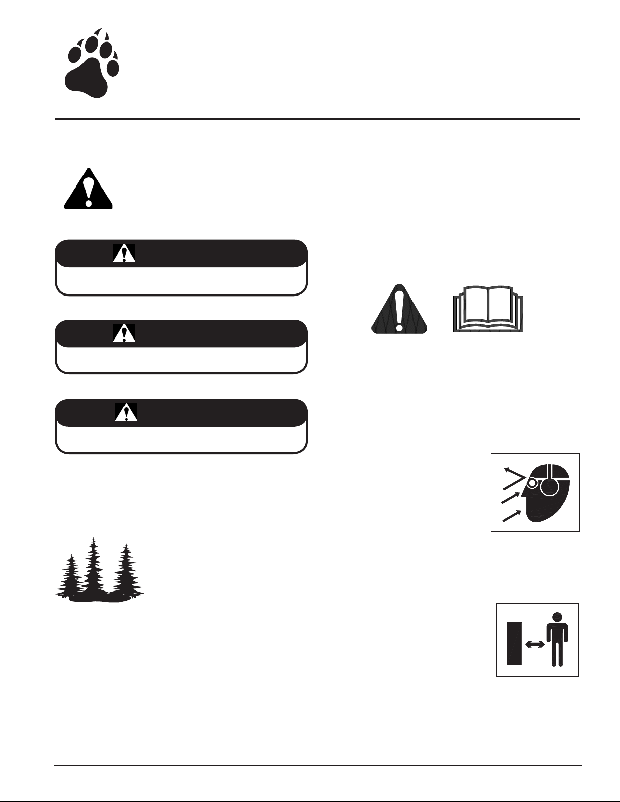
1
P/N 14942-00
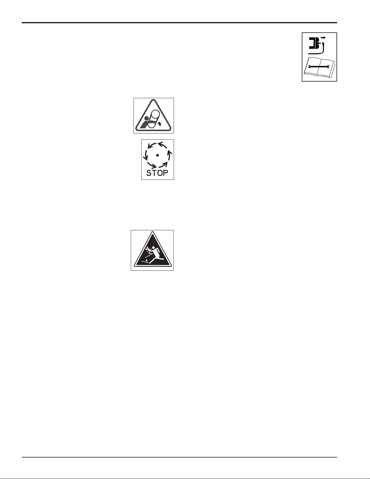
P/N 14984-00
2
OBTAIN AND WEAR SAFETY GLASSES
AND USE HEARING PROTECTION AT
ALL TIMES WHEN OPERATING THIS
MACHINE.
BEFORE INSPECTING OR SERVICING
ANY PART OF THIS MACHINE, SHUT
OFF POWER SOURCE, DISCONNECT
SPARK PLUG WIRE FROM SPARK
PLUG AND MAKE SURE ALL MOVING
PARTS HAVE COME TO A COMPLETE
STOP.
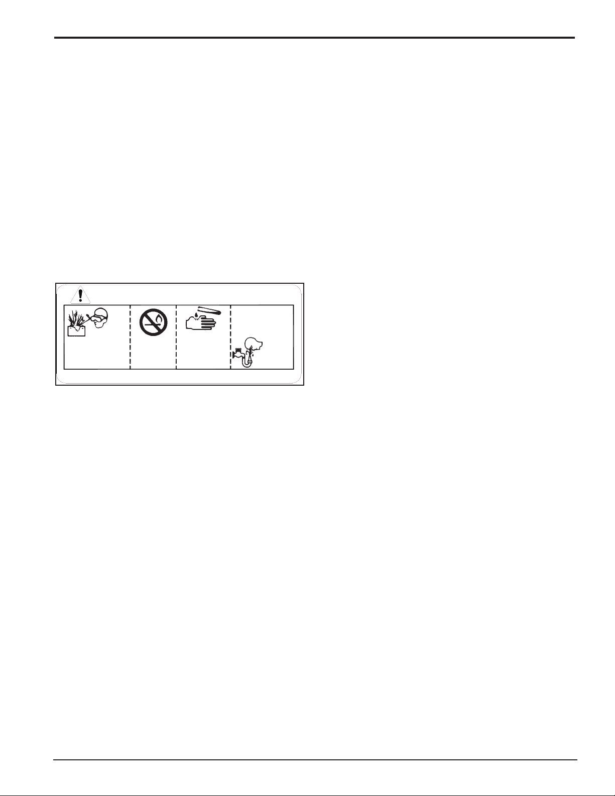
3
P/N 12252
KEEP MACHINE CLEAR OF DEBRIS
AND OTHER ACCUMULATIONS.
BUILD UP OF DEBRIS ON MACHINE
CAN CAUSE A FIRE.
BEFORE INSPECTING OR SERVICING
ANY PART OF THIS MACHINE, SHUT
OFF POWER SOURCE, DISCONNECT
SPARK PLUG WIRE FROM SPARK
PLUG AND MAKE SURE ALL MOVING
PARTS HAVE COME TO A COMPLETE
STOP.
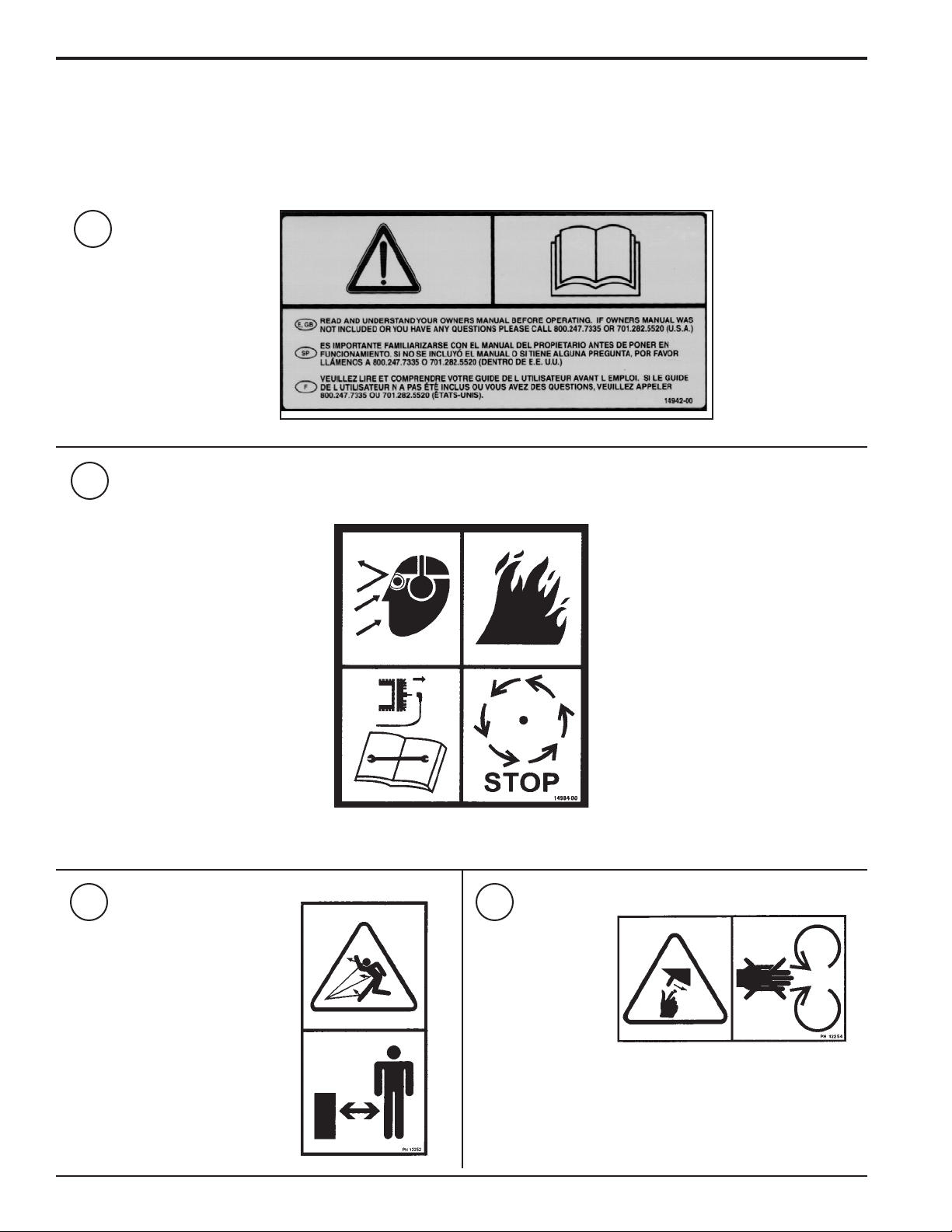
4
P/N 12254
DO NOT OPERATE THIS EQUIPMENT
IN THE VICINITY OF BYSTANDERS.
DO NOT ALLOW CHILDREN TO OPERATE THIS EQUIPMENT. ALWAYS
STAND CLEAR OF DISCHARGE AREA
WHEN OPERATING THIS MACHINE.
KEEP FACE AND BODY AWAY FROM
DISCHARGE AREAS.
6
DO NOT ALLOW HANDS OR ANY PART OF BODY OR CLOTHING NEAR ANY MOVING PART TO AVOID SERIOUS PERSONAL
INJURY.
Crary Bear Cat Owners Manual
SAFETY
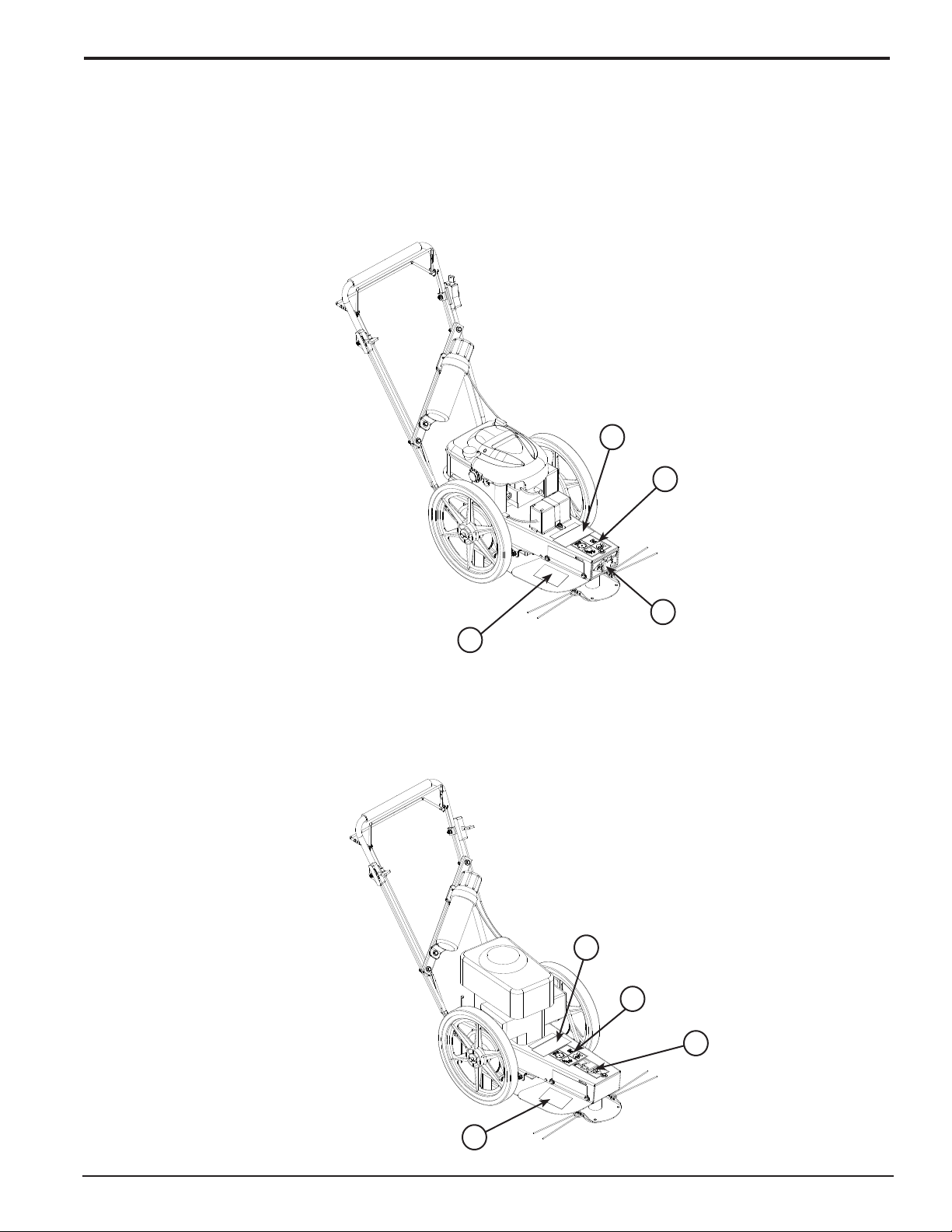
1.8 SAFETY DECAL LOCATIONS
The numbers below correspond to the decals in Section 1.7. Familiarize yourself with all of the safety and operational decals on the
machine and the associated hazards. See the engine owners manual or contact the engine manufacturer for engine safety instructions and decals. Make certain that all safety and operating decals on this machine are kept clean and in good condition. The decals
are shown below at reduced sizes. Refer to the parts catalog if you need a replacement decal. Decals that need replacement must
be applied to their original locations.
1.8.1 MODEL 73265
1
2
4
1.8.2 MODELS 73455, 74455, 75065, 75365, 76065
1
2
3
4
4
Crary Bear Cat Owners Manual
7
2
5/16" X 1" HEX HEAD BOLT
5/16" FLAT WASHER
5/16" NYLOCK NUT
5/16" X 2-1/4" BOLT
ASSEMBLY
Section
WARNING
Before inspecting or servicing any part of this machine, shut
off power source, disconnect spark plug wire from spark
plug and make sure all moving parts have come to a complete stop.
2.2 CHECKING/ADDING MOTOR OIL TO
ENGINE
Models: All models
Check the oil level and if needed ll the engine crankcase with
the type and amount of oil specied in the engine owners man-
ual.
IMPORTANT
If any bolts or nuts are dropped in the machine, be sure to
remove them before starting the machine.
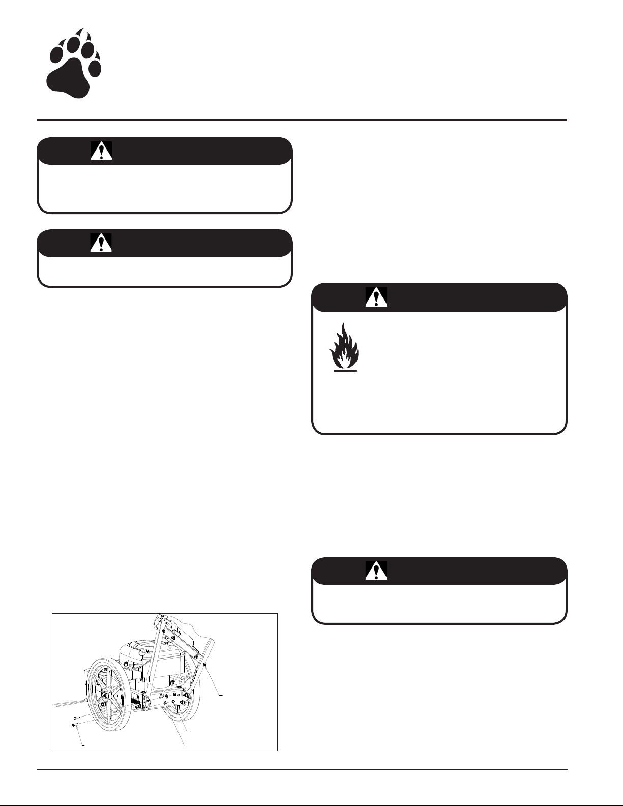
2.1 INSTALLING THE HANDLEBAR
Models: All models
Remove the trimmer and handlebar from the shipping box
1.
and pallet.
The manual container is partially assembled on one side of
2.
the handlebar. If necessary, loosen the bolt securing the
manual container to the handlebar. Rotate the container
and attach the remaining end to the opposite side of the
handlebar using one 5/16" x 2-1/4 bolt, washer and nut. DO
NOT TIGHTEN BOLTS AT THIS TIME.
Stand handlebar upright. Align the bottom hole on the
3.
handlebar with the bottom hole on the handlebar support
channel located on the trimmer and attach with two 5/16" x
1" bolts, washers and nuts (Figure 2.1). DO NOT TIGHTEN
BOLTS AT THIS TIME.
Adjust the handlebar height by rotating the handlebar until
4.
the top hole on the handlebar is aligned with a corresponding hole on the handlebar support channel and attach using
two 5/16" x 1" bolts, washers and nuts. DO NOT TIGHTEN
BOLTS AT THIS TIME.
Tighten the bolts securing the manual container to the
5.
handlebar.
Tighten all remaining bolts.
6.
2.3 FILLING THE TANK
Models: All models
DANGER
Gasoline is highly ammable and its vapors are
explosive. To prevent personal injury or prop-
erty damage:
Store gasoline only in approved containers,
in well ventilated, unoccupied buildings, away
from sparks or ames. Do not ll the fuel tank
while the engine is hot or running. Spilled fuel could ignite
if it comes in contact with hot parts or sparks from ignition.
Do not start the engine near spilled fuel. Never use gasoline
as a cleaning agent.
For best results use only clean, fresh, unleaded gasoline. Purchase gasoline in small quantities and store in clean, approved
containers. A container with a capacity of 2 gallons or less with
a pouring spout is recommended. Such a container is easier to
handle and helps eliminate spillage during refueling. Do not mix
oil with gasoline.
REFER TO THE ENGINE OWNERS MANUAL FOR FURTHER
FILLING INSTRUCTIONS.
IMPORTANT
Do not attempt to start the engine at this time. Wait until you
have read the complete starting instructions in the Operation Section of this manual.
8
Figure 2.1 - Installing the Handlebar
Crary Bear Cat Owners Manual

3
Section
FEATURES & CONTROLS
Understanding how your machine works will help you achieve
the best results when using your EZ Trim Mower. The following
descriptions dene the features and controls of your machine.
Refer to Figure 3.1 for feature locations.
REFER TO ENGINE OWNERS MANUAL FOR FURTHER EN
GINE OPERATING INSTRUCTIONS.
3.1 FUEL SHUT OFF VALVE
Models: All Models
The fuel shut off valve opens and closes the connection be
tween the fuel tank and the carburetor. If the engine is equipped
with a fuel shut off valve, turn it to the ON position for starting.
When the engine is not in use, leave the fuel valve lever in the
OFF position.
3.2 ENGINE THROTTLE
Models: 73265, 75065, 75365, 76065
Changes engine speed. Move throttle to the FAST position for
starting. Move throttle to the SLOW position to shut engine off.
The engine is intended to run at full RPM. Operate engine with
the throttle in the FAST position.
3.3 ENGINE CHOKE
Models: 73455, 74455
The throttle lever opens and closes the choke valve in the car
buretor and enriches the fuel mixture for starting a cold engine.
Move the throttle lever to the CHOKE position for starting.
When mowing or trimming, the throttle lever should be in the
RUN position.
3.7 SELF-PROPELLED BAIL
Models: 73265, 73455, 75365
Engages the self-propel mode. Pull up the self-propel bail located under the handlebar to start the self-propel mode.
-
3.8 SHIFT LEVER
Models: 73265, 73455, 75365
Used to adjust the trimmer speed. Position 1 is the slowest
and position 3 is the fastest. The ground speed ranges from
-
1-2 mph.
3.9 TILT CONTROL HANDLE
Models: 74455, 76065
Used to adjust the degree of tilt for the trimmer head and body
when using the Off Center Tilt (OCT) feature.
TRIMMER BAIL
SHIFT LEVER
-
SELF-PROPELLED
BAIL
THROTTLE
3.4 PRIMER BULB
Models: 73265, 75065, 75365, 76065
Use when starting a cold engine. Firmly push the primer bulb
3 times before starting.
3.5 TRIMMER BAIL
Models: All models
To start the trimmer, pull up the trimmer bail located under the
handlebar. When the trimmer bail is engaged, the trimmer disk
is rotating. Release the trimmer bail to stop the mower. Wait
until the trimmer disk has stopped rotating to inspect or service
the mower.
3.6 RECOIL STARTER
Models: 73455, 74455, 75065, 75365, 76065
Used to start engine. Grasp handle and slowly pull until resis
tance is felt. After resistance is felt, pull the cord quickly to start
the engine and prevent kickback.
Crary Bear Cat Owners Manual
TRIMMER BAIL
TILT CONTROL
HANDLE
-
Figure 3.1 - Feature Locations
9

4
Section
OPERATION
As with any other piece of outdoor power equipment, getting
the feel for how your machine operates and getting to know the
best techniques for particular jobs are important to overall good
performance.
trimming OPERATION
The trimming operation takes place under the body of the trim
mer, where trimmer string is mounted to a rotating disk. Mate
rial is trimmed and propelled out the edges of the trimmer.
WARNING
Before operating your machine, be sure you read and understand all safety, controls and operating instructions in this
Owner/Operators manual and on your machine. Failure to
follow these instructions can result in serious injury or property damage.
4.1 STARTING THE MOWER
Move the machine to a clear, level area outdoors before starting. Do not operate in the vicinity of bystanders. Make sure
the engine is clean and debris has not accumulated around the
mufer.
Check engine oil level before starting (see Engine Owners
1.
Manual).
Open the fuel shut-off valve.
2.
Place the throttle in the FAST position. Operate engine in
3.
the FAST position.
Firmly push the primer bulb 3 times before starting OR if the
4.
engine is equipped with a choke, move the throttle lever to
the CHOKE position.
Pull trimmer bail back.
5.
For Recoil Models: Grasp the recoil starter cord handle
6.
and slowly pull until resistance is felt, then pull quickly to
start the engine and prevent kickback. Repeat if necessary.
For Electric Models: Turn key to START.
Allow engine to warm up. Slowly adjust the throttle lever (if
7.
equipped) from the CHOKE position to the RUN position.
4.2 STOPPING THE MOWER
Move the throttle (if equipped) to the SLOW position, then
1.
release the trimmer bail OR move the throttle to the STOP
position.
Close the fuel shut off valve.
2.
-
-
WARNING
Allow the machine to come to complete stop before
inspection or servicing. You can tell when the machine
has come to a complete stop when the trimmer disk is not
rotating.
4.3 TRIMMING GUIDE
The intended use of the EZ Trim Mower is trimming, mowing
and edging. The following guidelines can help you get started.
Run unit at full operating speed before starting to trim, mow
1.
or edge.
To begin trimming, start the engine, place the trimmer head
2.
on the ground and begin walking slowly.
The wheels should remain on the ground at all times to
3.
prevent undue pressure on the trimmer head.
The cutting radius is dependant on the amount of cutting
4.
string used and type of application.
For difficult conditions and edging, using less than the full
5.
cutting radius is recommended.
WARNING
Inspect and clean engine before each use. Debris accumu-
lation around the mufer can cause a re.
10
Crary Bear Cat Owners Manual

OPERATION
RIGHT AXLE
NUT
SLOT
AXLE SHAFT
SLOT
SLOT
A
B
C
C
4.4 SELF-PROPELLED OPERATION
Models: 73265, 73455, 75365, 76065
The Self-Propelled EZ Trim Mower can be used in either push
or self-propelled mode.
Pull up the self-propelled bail located under the handlebar
1.
to start the self-propelled mode.
Adjust the trimmer speed with the shift lever. Position 1 is
2.
the slowest and position 3 is the quickest. The ground speed
ranges from 1-2 mph.
Operate mower safely and as intended.
3.
To stop the mower release the self-propelled bail.
4.
To stop the engine, release the trimmer bail.
5.
4.5 PARALLEL TRIMMING
Model: 75065
The EZ Trim Mower can be adjusted to mow at an angle. This
allows the machine to trim in hard to reach places. Parallel trim-
ming is adjustable on this model to the left 2". The trimmer body
pivots on the axle. To adjust the parallel trimming setting:
Loosen the right axle nut located on the bottom of the trimmer
1.
directly behind the axle shaft (Figure 4.1).
2.
Lift the right wheel and pull back. The wheel and axle will
rotate backwards due to a slot cut in the bottom of the trimmer frame.
3.
Tighten the nut loosened in Step 1.
When finished using the parallel trimming feature, loosen
4.
the right axle nut, and push the axle forward to the original
position.
Tighten the right axle bolt and resume regular trimming or
5.
mowing.
4.6 PARALLEL TRIMMING
Models: 73455, 75365
The EZ Trim Mower can be adjusted to mow at an angle. This
allows the machine to trim in hard to reach places. Parallel trim-
ming is adjustable on this model 2" to the left or the right. To
adjust the parallel trimming setting:
Loosen the two nuts on the bottom of the trimmer as shown in
1.
Figure 4.2; the first (A) is located behind the trimmer spindle,
while the other (B) is located behind the trimmer flap on the
transmission support plate. Do not adjust parallel trimming
with the trimmer axle. This will cause the drive chains to fall
out of adjustment.
Pivot the trimmer body, on the slotted holes, 2" to the left
2.
or right.
Tighten the nuts loosened in Step 1.
3.
When finished using the parallel trimming feature, loosen
4.
bolts A & B and place the trimmer body in the original position.
Tighten the bolts and resume regular trimming or mowing.
5.
Figure 4.2 - Adjusting the Mower
4.7 OFF CENTER TILT FEATURE (OCT)
Models: 74455, 76065
The OCT feature is used to trim in hard to reach places. This
feature enables both the trimmer head and body to tilt for trimming close to the ground. The degree of tilt is dependent on the
setting selected on the height adjustment handle located on the
right side of the EZ Trim Mower. To engage the OCT feature,
simply move the handle into one of the four settings that are
available.
Figure 4.1 - Adjusting the Mower
Crary Bear Cat Owners Manual
Level: The height adjustment handle is set in the position
1.
closest to the rear of the trimmer.
5.4 degrees: The height adjustment handle is set in the
2.
second position from the rear of the trimmer.
10.3 degrees: The height adjustment handle is set in the
3.
third position from the rear of the trimmer.
13 degrees: The height adjustment handle is set in the posi-
4.
tion closest to the front of the machine for maximum tilt.
11

5
SERVICE & MAINTENANCE
Section
5.1 MAINTENANCE SCHEDULE
The items listed in the service and maintenance schedule are to be checked, and if necessary, corrective action taken. This schedule is designed for units operating under normal conditions. If the unit is operating in adverse or severe usage conditions it may be
necessary for the items to be checked and serviced more frequently.
SEE ENGINE OWNERS MANUAL FOR FURTHER MAINTENANCE AND TROUBLESHOOTING INFORMATION.
SERVICE AND MAINTENANCE SCHEDULE
FREQUENCY
EVERY
COMPONENT
ENTIRE MACHINE CLEAN DEBRIS
ENGINE OIL CHECK OIL LEVEL
FUEL TANK FILL
NUTS & BOLTS CHECK
BATTERY
CONNECTIONS
AIR CLEANER CHECK & CLEAN
ENGINE OIL CHANGE
COOLING SHROUDS CLEAN
SPARK PLUG REPLACE
STARTER DRIVE SERVICE
SOLENOID SHIFT
STARTER
1
Perform more frequently in dusty, dirty or severe usage conditions.
2
Have a Briggs or Honda engine service dealer perform this service.
3
Change oil after rst 5 to 8 hrs of use, then every 50 hours or every season.
MAINTENANCE
REQUIRED
CHECK
1, 3
1, 2
2
DISASSEMBLE AND
2
CLEAN
BEFORE
EACH USE
1
25
HRS
EVERY
50
HRS
EVERY 100
HRS
EVERY 200
HRS
EVERY 500
HRS
12
Crary Bear Cat Owners Manual
SERVICE & MAINTENANCE
TRIMMER DISC
9/16" WRENCH
TRIMMER HEAD
WARNING
DISCONNECT SPARK PLUG WIRE FROM SPARK PLUG AND MAKE SURE ALL MOVING PARTS HAVE COME TO A COMPLETE STOP.
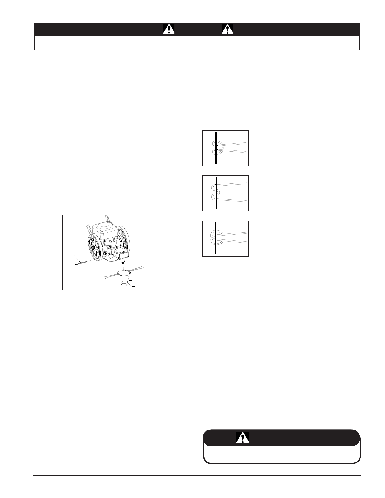
5.2 CUTTING HEIGHT ADJUSTMENT
The standard cutting height is 2-3/4 inches. Figure 5 below
shows the trimmer head assembled and set at the standard cutting height.
The cutting height can be adjusted down approximately 3/4 inch
by turning the trimmer head disk over. Adjust the cutting height
by following the steps below.
1.
Insert a 9/16” open end wrench into the trimmer frame
(Figure 5.1).
2.
Rotate the trimmer head until the wrench engages with the
trimmer shaft.
3.
While holding the wrench, twist the trimmer head weldment
counterclockwise to remove. Use a channel lock or pipe
wrench if necessary.
4.
Turn trimmer head disk over and replace on trimmer
spindle.
5.
Return trimmer head weldment and turn clockwise to
tighten.
BEFORE INSPECTING OR SERVICING ANY PART OF THIS MACHINE, SHUT OFF POWER SOURCE,
Loop the cutting string back and feed through the first hole
3.
on the opposite end of the trimmer head.
Feed through the remaining second hole and pull the cut-
4.
ting string tight. The cutting strings in the middle two holes
should be the same length. If the length differs, cut to an
even length.
When completed, the trimmer head should resemble Figure
5.2.
Figure 5.2
Wrapping the Cutting String
Figure 5.3
Optional Wrapping Method
Figure 5.1 - Cutting Height Adjustment
5.3 CUTTING STRING REPLACEMENT
Cutting string is available in two thicknesses, .130 mil (standard) and .155 mil (heavy duty). The type of string selected is
dependent on the conditions and material being cut.
String heavier than .155 mil can be used by making the holes
in the trimmer head larger. The decision to drill the holes bigger may shorten the life of .130 mil and .155 mil string if used
again.
Cutting string can be wrapped in a variety of ways. Refer to
Figures 5.2, 5.3 and 5.4 for examples. The wrapping method
and cutting string thickness chosen is ultimately based on what
is determined the best for the operator.
To wrap the cutting string in the standard conguration, follow
the steps below.
Feed the cutting string through the second hole on either
1.
end of the trimmer head leaving approximately 8 inches
for the cutting surface. Total recommended string length
is 20-1/2 inches.
Continue by weaving the cutting string through the first hole
2.
directly beside the second hole used in Step 1. Pull the
cutting string tight.
Crary Bear Cat Owners Manual
Figure 5.4
Optional Wrapping Method
5.4 DRIVE CHAIN ADJUSTMENT
Models: 73455, 75365
Self-propelled models operate with a drive chain. Periodically,
this chain will need to be adjusted. To adjust:
Loosen the two 5/16” nuts (C) (Figure 4.2) located under
1.
the trimmer axle.
Slide the trimmer axle back to tighten the chains. Slide the
2.
trimmer forward to loosen the chains.
Retighten the nuts.
3.
5.5 ENGINE MAINTENANCE
Maintenance is essential in preserving engine life. Clean the
engine periodically to remove grass and buildup. The engine
owners manual addresses cleaning the air lter and changing
the oil. Service engine according to the maintenance schedule
in your engine owners manual.
Remember to inspect and clean engine cooling ns as needed.
IMPORTANT
Clean grass and buildup from the engine periodically. Dusty
conditions will require frequent cleaning.
13

6
TROUBLESHOOTING
Section
Before performing any of the corrections in this troubleshooting chart, refer to the appropriate information contained in this manual
for the correct safety precautions and operating or maintenance procedures. Contact your nearest dealer or the factory for service
problems with the machine.
PROBLEM POSSIBLE CAUSE REMEDY
Broken off or damaged belts.
Trimmer disk does not turn.
Cutting is slow or rough.
Trimmer requires excessive
power or stalls.
Drive belt squealing or smoking.
Engine won't start or
is hard to start.
Drive belt rolling or falling off
pulleys.
Drive chain falling off
self-propelled models.
1.
Broken spindle.
2.
Failed bearings.
3.
Cutting string is too weak.
1.
Growth is too thick or heavy.
2.
Engine not running at full RPM.
3.
Cutting string is too long.
1.
Drive belt is loose or worn.
2.
Growth is too thick or heavy.
3.
Belt too tight
4.
Drive belt is loose or worn.
1.
Worn or damaged pulley.
2.
Gas tank is empty.
1.
Spark plug wire is disconnected.
2.
Spark plug is defective.
3.
Gas line is obstructed
4.
Dirty, stale, water-contaminated
5.
gas.
Flooded engine.
6.
Dirty or plugged air cleaner or
7.
engine cooling fins.
Trimmer bail not engaged.
8.
Pulley not aligned.
1.
Belt not tensioned properly.
2.
Spindle bearing failed.
3.
Loose chain.
1.
Worn chain.
2.
Worn sprocket.
3.
Sprocket not aligned.
4.
Replace belts.
1.
Repair spindle.
2.
Repair bearings.
3.
Replace with heavier cutting string (.155).
1.
Reduce the trimming area by half or raise the
2.
trimmer head off the ground.
Speed up engine to full throttle.
3.
Reduce cutting string length.
1.
Replace drive belt.
2.
Reduce the trimming area by half or raise the
3.
trimmer head slightly off the ground.
Move spindle hub assembly towards the rear of
4.
the trimmer.
Replace drive belt.
1.
Replace pulley.
2.
Fill gas tank.
1.
Connect loose wire to the spark plug.
2.
Replace spark plug.
3.
Remove gas line at carburetor and check for
4.
obstruction. Drain gas tank and refill with fresh
gasoline.
Drain tank and fill with fresh gasoline.
5.
Put throttle control in run position and crank en-
6.
gine several times to clear out excess gas.
Clean or replace air cleaner. Clean cooling fins
7.
and shroud area of engine.
Engage trimmer bail
8.
Align pulleys.
1.
Tension belt with 70 lbs of force.
2.
Replace bearing.
3.
Tighten chain.
1.
Replace chain.
2.
Replace sprocket.
3.
Align drive sprocket and wheel clutch assembly
4.
with washers.
14
Crary Bear Cat Owners Manual

7
SPECIFICATIONS
Section
7.1 MOWER SPECIFICATIONS
MODEL
73265 73455 74455 75065 75365 76065
ENGINE
HORSEPOWER
DRIVE 3-Spd Self-Prop 3-Spd Self-Prop Push Push 3-Spd Self-Prop Push
CUTTING
WIDTH
WHEEL SUP
PORT
CUTTING
HEIGHT
NYLON CUT
TING STRING
PARALLEL
TRIMMING
TILT HEAD
WEIGHT
OVERALL
LENGTH
OVERALL
HEIGHT
OVERALL
WIDTH
FRAME MATE
RIAL
HANDLEBARS
AND BAIL
START
FUEL CAPACITY
UNIT WAR
RANTY
ENGINE WAR
RANTY
CONTROL
VIBRATION
LEVEL
NOISE LEVEL
-
-
-
-
-
B & S
Quantam
6.5 HP 5.5 HP 5.5 HP 6.5 HP 6.5 HP 6.5 HP
24" 24" 24" 24" 24" 24"
Ball Bearings Ball Bearings Ball Bearings Ball Bearings Ball Bearings Ball Bearings
1-7/8" & 2-3/4" 1-7/8" & 2-3/4" 1-7/8" & 2-3/4" 1-7/8" & 2-3/4" 1-7/8" & 2-3/4" 1-7/8" & 2-3/4"
Heavy Duty
(.155)
Standard (.130)
OPTIONAL
Manual Manual
No No Mechanical No No Mechanical
84 lbs. 86 lbs. 82 lbs. 77 lbs. 85 lbs. 77 lbs.
50" 50" 50" 50" 50" 50"
38" 38" 38" 38" 38" 38"
21" 21" 21" 21" 21" 21"
Solid steel Solid steel Solid steel Solid steel Solid steel Solid steel
Powder baked
paint with
foam grip
Electric Recoil Recoil Recoil Recoil Recoil
1.5 qt. 1.2 qt. 1.2 qt. 1.5 qt. 1.5 qt, 1.5 qt.
2 yr. consumer;
90 day
commercial.
See engine
owners manual.
<2.5 m/s2 <2.5 m/s2 <2.5 m/s2 <2.5 m/s2 <2.5 m/s2 <2.5 m/s2
101 dB 98dB 98 dB 101 dB 101 dB 101 dB
Honda OHC Honda OHC
Heavy Duty
(.155)
Standard (.130)
OPTIONAL
Powder baked
paint with
foam grip
2 yr. consumer;
90 day
commercial.
See engine
owners manual.
Heavy Duty
(.155)
Standard (.130)
OPTIONAL
Standard Manual Manual Standard
Powder baked
paint with
foam grip
2 yr. consumer;
90 day
commercial.
See engine
owners manual.
B & S
Intek
Heavy Duty
(.155)
Standard (.130)
OPTIONAL
Powder baked
paint with
foam grip
2 yr. consumer;
90 day
commercial.
See engine
owners manual.
B & S
Intek
Heavy Duty
(.155)
Standard (.130)
OPTIONAL
Powder baked
paint with
foam grip
2 yr. consumer;
90 day
commercial.
See engine
owners manual.
B & S
Intek
Heavy Duty
(.155)
Standard (.130)
OPTIONAL
Powder baked
paint with
foam grip
2 yr. consumer;
90 day
commercial.
See engine
owners manual.
Crary Bear Cat Owners Manual
15

SPECIFICATIONS
A
SAE - 2
SAE - 5
SAE - 8
A
4.8
8.8
10.9
12.9
7.2 BOLT TORQUE
The tables below are for reference purposes only and its use by anyone is entirely voluntary, unless otherwise noted. Reliance on its
contents for any purpose is at the sole risk of that person. Crary Bear Cat is not responsible for any loss or damage resulting from the
use of this information. In developing these tables, Crary Bear Cat has made a determined effort to present the contents accurately.
ENGLISH
BOLT DIAMETER
(A)
1/4" 7.5 5.5 11 8 16 12
5/16" 15 11 23 17 34 25
3/8" 27 20 41 30 61 45
7/16" 41 30 68 50 95 70
1/2" 68 50 102 75 149 110
9/16" 97 70 149 110 203 150
5/8" 122 90 203 150 312 230
3/4" 217 160 353 260 515 380
7/8" 230 170 542 400 814 600
1" 298 220 786 580 1220 900
1-1/8" 407 300 1085 800 1736 1280
1-1/4" 570 420 2631 1940 2468 1820
SAE 2 SAE 5 SAE 8
N.m Ft-lb. N.m Ft-lb. N.m Ft-lb.
BOLT TORQUE *
METRIC
BOLT DIAMETER
(A)
M3
M4
M5
M6
M8
M10
M12
M14
M16
M18
M20
M22
M24
M27
4.8 8.8 10.9 12.9
N.m Ft-lb. N.m Ft-lb. N.m Ft-lb. N.m Ft-lb.
0.5 0.4 - - - - - 3 2.2 - - - - - 5 4 - - - - - 6 4.5 11 8.5 17 12 19 14.5
15 11 28 20 40 30 47 35
29 21 55 40 80 60 95 70
50 37 95 70 140 105 165 120
80 60 150 110 225 165 260 190
125 92 240 175 350 255 400 300
175 125 330 250 475 350 560 410
240 180 475 350 675 500 800 580
330 250 650 475 925 675 1075 800
425 310 825 600 1150 850 1350 1000
625 450 1200 875 1700 1250 2000 1500
* Torque value for bolts and capscrews are identied by their head markings.
Torque gures indicated above are valid for non-greased or non-oiled threads and heads unless otherwise specied. Therefore,
do not grease or oil bolts or capscrews unless otherwise specied in this manual. When using locking elements, increase torque
values by 5%.
16
BOLT TORQUE *
Crary Bear Cat Owners Manual
 Loading...