

Page 1

Service Manual
Fuller Heavy Duty Transmissions
TRSM0503
October 2007
RTX-12510
RTX-12515
RTXF-12510
RTXF-12515
Page 2

For parts or service call us
Pro Gear & Transmission, Inc.
1 (877) 776-4600
(407) 872-1901
parts@eprogear.com
906 W. Gore St.
Orlando, FL 32805
Page 3

Table of Contents
Model Designations . . . . . . . . . . . . . . . . . . . . . . . . . . . ...3
Description . . . . . . . . . . . . . . . . . . . . . . . . . . . . . . . . . ...4
Specifications . . . . . . . . . . . . . . . . . . . . . . . . . . . . . . . ...6
Lubrication . . . . . . . . . . . . . . . . . . . . . . . . . . . . . . . . . . ...8
Operation . . . . . . . . . . . . . . . . . . . . . . . . . . . . . . . . . . ..10
Air Systems . . . . . . . . . . . . . . . . . . . . . . . . . . . . . . . . ...16
Preventive Maintenance . . . . . . . . . . . . . . . . . . ...24
Changing Input Shaft . . . . . . . . . . . . . . . . . . . . . . . . . ...26
Disassembly Precautions . . . . . . . . . . . . . . . . . . . . . . ...27
Disassembly Instructions
I. Shifting Controls . . . . . . . . . . . . . . . . . . . . . . . . . ...28
A. Deep Reduction Air System (RT-12515) . . . . ...29
B. Range Shift Air System . . . . . . . . . . . . . . . . . . ...29
C. Gear Shift Lever Housing . . . . . . . . . . . . . . . . ...32
D. Shift Bar Housing . . . . . . . . . . . . . . . . . . . . . . ...33
II. companion Flange, Auxiliary Housing and
Clutch Housing . . . . . . . . . . . . . . . . . . . . . . . . . . ...36
111. Front Section . . . . . . . . . . . . . . . . . . . . . . . . . . . ...38
A. Auxiliary Drive Gear .. . . . . . . . . . . . . . . . ...38
B. Left Reverse Idler Gear .... . . . . . . . . . . . . . . ...39
C. Countershaft Bearings . . . . . . . . . . . . . . . . . . . ...41
D. Mainshaft . . . . . . . . . . . . . . . . . . . . . . . . . . . . ...42
E. Drive Gear . . . . . . . . . . . . . . . . . . . . . . . . . . . . ...43
F. Countershafts . . . . . . . . . . . . . . . . . . . . . . . . . ...45
G. Right Reverse Idler Gear .. . . . . . . . . . . . . . . ...45
IV. Auxiliary Section –RT-1110 Series . . . . . . . . . . ...46
A. Range Shift Cylinder . . . . . . . . . . . . . . . . . . . . ...46
B. Auxiliary Countershafts . . . . . . . . . . . . . . . . . ...47
C. Synchronizer . . . . . . . . . . . . . . . . . . . . . . . . . . ...47
D. Low Speed Gear and Output Shaft . . . . . . . . . ...48
V. Auxiliary Section –RT-12510 Series . . . . . . . . . ...50
A. Range Shift Cylinder . . . . . . . . . . . . . . . . . . . . ...50
B. Auxiliary Counershafts . . . . . . . . . . . . . . . . . ...52
C. Synchronizer . . . . . . . . . . . . . . . . . . . . . . . . . . ...53
D. Output Shaft . . . . . . . . . . . . . . . . . . . . . . . . . . ...54
VI. Auxiliary Section –RT-12515 Series . . . . . . . . . ...56
A. Range Shift Cylinder . . . . . . . . . . . . . . . . . . . . ...56
B. Auxiliary Counterhafts . . . . . . . . . . . . . . . . . ...58
C. Synchronizer . . . . . . . . . . . . . . . . . . . . . . . . . . ...59
D. Low Range Gear and Range Mainshaft . . . . . . ...60
E. Deep Reduction Shift Cylinder . . . . . . . . . . . . ...62
F. Output Shaft . . . . . . . . . . . . . . . . . . . . . . . . . . ...63
Inspection . . . . . . . . . . . . . . . . . . . . . . . . . . . . . . . . . ...64
Torque Ratings . . . . . . . . . . . . . . . . . . . . . - . . . . . . . ...66
Reassembly Precautions . . . . . . . . . . . . . . . . . . . . . . . ...68
Reassembly Instructions
I. Auxiliary Section-RT-1110 Series . . . . . . . . . . ...69
A. Output Shaft . . . . . . . . . . . . . . . . . . . . . . . . . . ...69
B. Synchronizer . . . . . . . . . . . . . . . . . . . . . . . . . . ...71
C. Auxiliary Countershafts . . . . . . . . . . . . . . . . . ...72
D. Range Shift Cylinder . . . . . . . . . . . . . . . . . . . . ...74
II. Auxiliary Section –RT-12510 Series . . . . . . . . . ...76
A. Output Shaft . . . . . . . . . . . . . . . . . . . . . . . . . . ...76
B. Synchronizer . . . . . . . . . . . . . . . . . . . . . . . . . . ...80
C. Auxiliary Countershafts . . . . . . . . . . . . . . . . . ...81
D. Range Shift Cylinder . . . . . . . . . . . . . . . . . . . . ...82
III. Auxiliary Section –RT-12515 Series . . . . . . . . . ...84
A. Output Shaft . . . . . . . . . . . . . . . . . . . . . . . . . . ...84
B. Range Mainshaft . . . . . . . . . . . . . . . . . . . . . . . ...89
C. Deep Reduction Shift Cylinder . . . . . . . . . . . . ...90
D. Low Range Gear . . . . . . .
E. Synchronizer . . . . . . . . . .
F. Auxiliary Countershafts .
G. Range Shift Cylinder . . . .
IV. Front Section . . . . . . . . . . .
A. Right Reverse Idler Gear .
B. Countershafts . . . . . . . . .
C. Countershaft Installation
D. Drive Gear . . . . . . . . . . . .
E. Drive Gear Installation . .
F. Left Countershaft Timing
Mainshaft Axial Clearances . . . .
G. Mainshaft . . . . . . . . . . . .
H. Mainshaft Installation . . .
I. Left Reverse Idler Gear . .
J. Mainshaft Final Installation . . . . . . . . . . . . . ...113
K. Auxiliary Drive Gear . . . . . . . . . . . . . . . ...114
V. Companion Flange, Auxiliary Housing and
Clutch Housing . . . . . . . . . . . . . . . . . . . . . . . . . ...116
VI. Shifting Controls . . . . . . . . . . . . . . . . . . . . . . . . ...118
A. Shift Bar Housing . . . . . . . . . . . . . . . . . . . . . ...118
B. Gear Shift Lever Housing . . . . . . . . . . . . . . . ...121
C. Air System . . . . . . . . . . . . . . . . . . . . . . . . . . ...122
Tool Reference . . . . . . . . . . . . . . . . . . . . . . . . . . . . ...124
2
Page 4

Model Designations
RT-lll O– Roadranger
RTO-1 110 –- Roadranger
1100 Ibs.-ft,
RT-12510 – Roadranger
RTO-12510 – Roadranger
1250 Ibs.-ft.
RT-12515 – Roadranger
RTO-1 2515 – Roadranger
1250 Ibs.-ft.
“F” –
Included in
ward position of the gear shift lever.
transmission, twin countershaft, 10 speeds, 1100 lbs./ft. torque capacity.
transmission, twin countershaft, 10 speeds, including an overdrive ratio,
torque capacity.
transmission, twin countershaft, 10 speeds, 1250 lbs./ft. torque capacity.
transmission, twin countershaft, 10 speeds, including an
torque capacity.
transmission, twin countershaft, 15 speeds, 1250 lbs./ft.
transmission, twin countershaft, 15 speeds, including an
letter
before numerals, such as RTF-12510, etc. denotes for-
overdrive ratio,
torque capacity
overdrive ratio,
NOTE
Illustrated parts lists with part numbers are available upon request. Write Service Department, Eaton Corporation,
Transmission Division, 222 Mosel Avenue, Kalamazoo,
Michigan 49007.
3
Page 5

Description
The RT-111 O and RT-12510 transmissions are designed for
heavy-duty on-highway equipment. The twin countershaft
design, which splits torque equally between the two shafts,
provides a high torque capacity to weight ratio . Because of
torque splitting, each gear set carries only half the load,
greatly reducing the face width of each gear.
Another unique design feature is the floating gear principle.
The mainshaft gears when not engaged “float” between the
countershaft gears, eliminating the need for gear sleeves and
bushings. All gears are in constant mesh and have spur type
teeth.
The RT-111 O and RT-12510 transmissions have ten forward speeds and two reverse, consisting of a five-speed
front section and a two-speed auxiliary or range section,
both contained in one case. First through fifth speeds are
obtained by using the five gear ratios in the front section
through the low speed gear of the range section. Sixth
through tenth speeds are obtained by using the five gear
ratios in the front section through the high speed (direct
drive) range gear. As in other Roadranger transmissions, the
ratios are progressively spaced.
The RT-125 15 transmissions have 15 forward speeds and
three consisting of a five-speed front section, which
is identical to the RT-1 110 and RT-1251O front section,
and a three-speed auxiliary or range section. Both sections
are contained in one case, the rear plate being extended to
accommodate the extra set of gears. The 15 speeds are
obtained by using the five speeds of the front section
through direct drive (high range), through the low speed
range gear, and through the hole-gear of the auxiliary sec-
tion. The hole-gear in the RT-12515 transmissions is
engaged by air when selected by the driver.
4
Page 6

5
Page 7
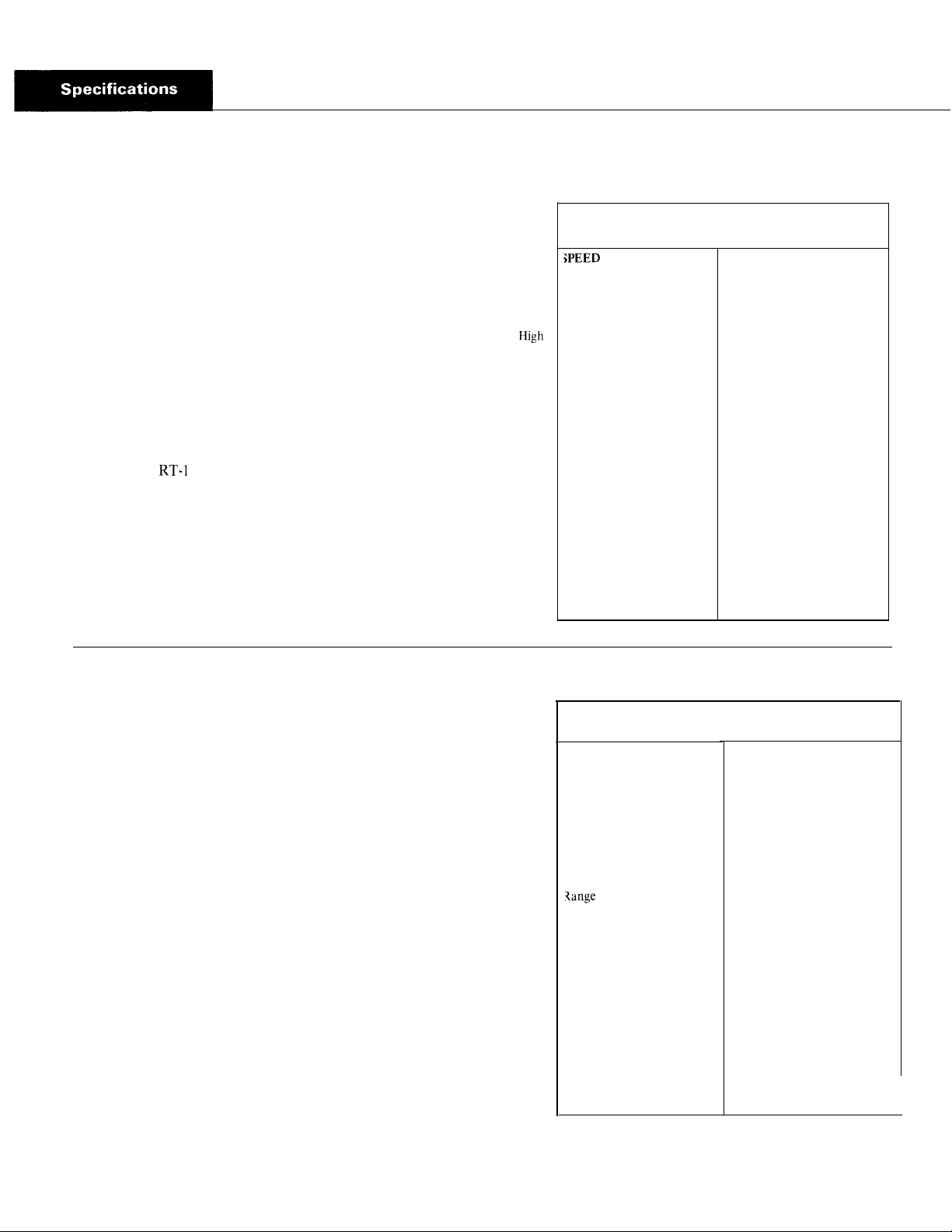
Specifications - RT-1 110 Series
Speeds 10 progressive forward speeds, 2 reverse
Nominal Torque Capacity 1100 lb.-ft.
Input Drive Shaft 2“ diameter
Power Take-Off
Openings
Right Side: SAE standard 6 bolt regular duty type, short length.
Bottom: SAE standard 8-bolt heavy-duty type.
PTO Gear Relative Speed to Input R.P. M.
Right
Side: 45-tooth 6/8 pitch gear turning at .700 engine
speed on RT-1 110 and RTF-1 110 models; .888 engine
speed on RTO-1 110 and RTOF-1 110 models.
Bottom: 47-tooth 6/8 pitch gear turning at .700 engine
speed on 110 and RTF-1 110 models, .888 engine
speed on RTO-1 110 and RTOF-1 110 models.
Weight
SAE No. 1 aluminum clutch housing with standard controls,
less clutch release parts – 620 lbs.
Oil Capacity
Approximately 25 pints, depending on inclination of engine
and transmission. Fill to level of case filler opening.
Range
Low
Range
GEAR RATIOS
RT-111O and RTF-111O
RATIO % STEP
10th
Range Shift
1.00
1.27 ‘
9th
1.65
8th
7th
2.11
6th
2.74
3.55
5th
4th
4.50
3rd
5.83
2nd
7.49
1 St
9.71
High
Reverse 2.74
Low
Reverse 9.71
27 27
30 30
28
30 30
30
27
30 30
28
30
RTO-1 110 and RTOF-1 110
SPEED RATIO % STEP
10th
9th
8th
7th
6th
Range Shift
5th
4th
3rd
2nd
1 St
High
Reverse 2.16
Low
Reverse 7.65
.79
1.00
1.30
28
1.66
2.16
29
2.79
27
3.55
4.59
28
5.90
30
7.65
I
I
Specifications - RT-I 2510 Series
Speeds
Nominal Torque Capacity 1250 lb.-ft.
Power Take-Off
PTO Gear Relative Speed to Input R.P.M.
Weight
Clutch Housing Size
Oil Capacity
10 progressive forward speeds, 2 reverse.
Openings
Right Side: SAE standard 6-bolt regular duty type, short length.
Bottom: SAE standard 8-bolt heavy-duty type.
Right Side: 45-tooth 6/8 pitch gear turning at .700 engine
speed on RT-1 2510 and RTF-12510 models, .888 engine
speed on RTO-1 2510 and RTOF-1251O models.
Bottom: 47-tooth 6/8 pitch gear turning at .700 engine
speed on RT-1251O and RTF-1 2510 models, .888 engine
speed on RTO-1 2510 and RTOF-12510 models.
SAE No. 1 clutch housing with standard controls, less clutch
release parts – 698 lbs.
SAE No. 1 deep only, 6-5/8”, for push or pull type clutches.
Approximately 25 pints, depending on inclination of engine
and transmission. Fill to level of case filler opening.
High
Range
Low
Range
GEAR RATIOS
RT-1251O and RTF-1251O
;PEED RATIO % STEP
9th
8th
7th
6th
5th
4th
3rd
2nd
1 St
Shift
1.00
1.27
1.65
2.11
2.74
3.55
4.50
5.83
7.49
9.71
2.74
9.71
27
29
28
30
29
27
29
28
30
10th
High
Reverse
Low
Reverse
RTO-125 10 and RTOF-12510
SPEED RATIO % STEP
10th
9th
8th
7th
6th
Range Shift
5th
4th
3rd
2nd
1 St
High
Reverse
Low
Reverse
.79
1.00
1.30
1.66
2.16
2.79
3.55
4.59
5.90
7.65
2.16
7.65
27
30
28
30
29
27
30
28
30
Page 8

Specifications -
RT-1 2515 Series
Speeds
15 forward speeds, 3 reverse. Five deep reduction ratios,
plus evenly spaced ratios for a selective 11 or 12 progressive
ratios.
Nominal Torque Capacity
1250 lb.-ft.
Power Take-Off
Openings
Right Side: SAE standard 6-bolt regular duty type, short length.
Bottom: SAE standard 8-bolt heavy-duty type.
PTO Gear Relative Speed to Input R.P. M.
RT-12515 and RTF-12515
Right Side: 45-tooth 6/8 pitch gear turning .700 engine speed.
Bottom: 47-tooth 6/8 pitch gear turning .700 engine speed.
GEAR RATIOS
RTO-12515 and RTOF-125 15
RANGE
SPEED % STEP RATIO % STEP SPEED
.79
1.00
1.30
1.66
2.16
29
2.79
1 St
10th
27
9th
30
8th
28
7th
30
6th
5th
27
4th
30
3rd
28
2nd
30
1 St
Deep
Red.
Range
RATIO %
10.93
STEP
3.99
27
5.07
29
6.56
28
8.43
29
High Reverse . . . . . . . . . . . . . . . . . . . . 2.16
Low Reverse . . . . . . . . . . . . . . . . . . . . . 7.65
Deep Reduction Reverse . . . . . . . . . ...10.93
High
Range
Low
Range
RTO-12515 and RTOF-12515
Right Side: 45-tooth 6/8 pitch gear turning .888 engine speed.
Bottom: 47-tooth 6/8 pitch gear turning .888 engine speed.
Clutch Housing Size
SAE No. 1 deep only, 6-5/8”, for push or pull type clutches.
Weight
SAE No. 1 clutch housing, with standard controls, less clutch
release parts – 770 lbs.
Oil Capacity
Approximately 28 pints, depending on inclination of engine
and transmission. Fill to level of case filler opening.
GEAR RATIOS
RT-12515 and RTF-12515
RATIO % STEP SPEED % STEP % STEP SPEED
Deep
Red.
Range
5.07
6.43
8.34
10.70
13.87
27
30
28
29
High Reverse . . . . . . . . . . . . . . . . . . . . . . . . 2.74
Low Reverse . . . . . . . . . . . . . . . . . . . . . . . . 9.71
Deep Reduction Reverse . . . . . . . . . . . . ...13.87
RANGE
5th
3rd’
1 St
29
/
1.00
1.27
1.65
2.11
2.74
3.55
4.50
5.83
7.49
9.71
27
10th
9th
29
8th
28
7th
30
6th
5th
27
4th
29
3rd
28
2nd
30
1 St
High
Range
Low
Range
Page 9

LUBRICATION
, ... . . .
Proper
Lubrication . . .
the Key to long
transmission life
Proper lubrication procedures are the key to a
good all-around maintenance program. If the
oil is not doing its job, or if the oil level is
ignored, all the maintenance procedures in the
world are not going to keep the transmission
running or assure long transmission life.
so that the internal parts operate in a bath of
oil circulated by the motion of gears and shafts.
these procedures are closely followed:
Eaton
First 3,000 to 5,000 miles
(4827 to 8045 Km)
Every 10,000 miles
(16090 Km)
Every 250,000 miles
(402336 Km)
Every 100,000 miles (160,000 Km)
or every 3 years whichever occurs first fluid.
I
First 30 hours Factory fill Initial drain,
Every 40 hours Inspect fluid level Check for leaks
Every 500 hours Change transmission fluid where
I
Every 1,000 hours
I
I
First 3,000 to 5,000 miles Factory fill
(4827 to 8045 Km)
I
Every 10,000 miles
(16090 Km)
I
Every 50,000 miles
(80450 Km)
I
I
First 30 hours Change transmission lubricant on new units
Every 40 hours
Every 500 hours Change transmission Iubricant where
Every 1,000 hours Change transmission Iubricant
Change the oil filter when fluid or lubricant is changed.
®
Eaton
Fuller®Transmissions are designed
Thus, ail parts will be amply lubricated if
1. Maintain oil level. Inspect regularly.
2. Change oil regularly.
3. Use the correct grade and type of oil.
4. Buy from a reputable dealer.
Lubrication Change and Inspection
®
Roadranger®CD50 Transmission Fluid
HIGHWAY USE—Heavy Duty and Mid-Range
Factory fill
Inltlal drain
Check fluid level
Check for leaks
Heavy Duty Highway Change Interval
Change transmission
Mid-Range Highway Change Interval
Change transmission
OFF-HIGHWAY USE
severe dirt conditions exist.
Change transmission fluid
(Normal off-highway use),
Heavy Duty Engine Lubricant or
Mineral Gear Lubricant
HIGHWAY USE
Initial drain.
Inspect Iubricant level,
Check for leaks,
Change transmission
OFF-HIGHWAY USE
Inspect Iubricant level Check for leaks
severe dirt conditions exist.
(Normal off-highway use),
lubricant,
fluid,
Recommended Lubricants
Fahrenheit
(Celsius)
Ambient
Temperature
All
Above 10oF(-12oC.)
Above 10oF(-12oC.)
Below 10oF(-12oC.)
Above 10oF(-12oC.)
Below 10oF(-12oC.)
®
Grade
(SAE)
50
50
40
90
80W
Type
Eaton®Roadranger
CD50 Transmission
Fluid
Heavy Duty Engine 011
MI L-L-2104B C or D or
API-SF or API-CD
(Previous API designations 30
acceptable)
Mineral Gear 011 with rust
and oxidation Inhibitor
API-GL-1
The use of mild EP gear oil or multi-purpose gear oil is not recommended, but if
these gear oils are used, be sure to adhere to
the following limitations:
Do not use mild EP gear oil or multi-purpose gear oil when operating temperatures are
above 230°F (110
o
C). Many of these gear oils,
particularly 85W140, break down above 230°F
and coat seals, bearings and gears with deposits that may cause premature failures. If
these deposits are observed (especially a coating on seal areas causing oil leakage), change
to Eaton Roadranger CD50 transmission fluid,
heavy duty engine oil or mineral gear oil to
assure maximum component life and to maintain your warranty with Eaton. (Also see
“Operating Temperatures”.)
Additives and friction modifiers are not recom-
mended for use in Eaton Fuller transmissions.
Proper Oil Level
Make sure oil is level with filler opening. Because you can reach oil with your finger does
not mean oil is at proper level. One inch of oil
level is about one gallon of oil.
Draining Oil
Drain transmission while oil is warm. To drain
oil remove the drain plug at bottom of case.
Clean the drain plug before re-installing.
Refilling
Clean case around filler plug and remove plug
from side of case. Fill transmission to the
level of the filler opening. If transmission has
two filler openings, fill to level of both openings.
The exact amount of oil will depend on the
transmission inclination and model. Do not
over fill—this will cause oil to be forced out
of the transmission.
When adding oil, types and brands of oil
should not be mixed because of possible incompatibility.
4
Page 10
LUBRICATION
Operating Temperatures
—With Eaton
®
Roadranger
®
CD50 Transmission Fluid
Heavy Duty Engine Oil
and Mineral Oil
The transmission should not be operated con-
sistently at temperatures above 250
However, intermittent operating temperatures
o
to 300
F (149oC) will not harm the transmission. Operating temperatures above 250
increase the lubricant’s rate of oxidation and
shorten its effective life. When the average
operating temperature is above 250
transmission may require more frequent oil
changes or external cooling.
The following conditions in any combina-
tion can cause operating temperatures of over
o
F: (1) operating consistently at slow
250
speeds, (2) high ambient temperatures, (3) restricted air flow around transmission, (4) exhaust system too close to transmission, (5)
high horsepower, overdrive operation.
External oil coolers are available to reduce
operating temperatures when the above conditions are encountered.
o
F (120oC).
o
F
o
F, the
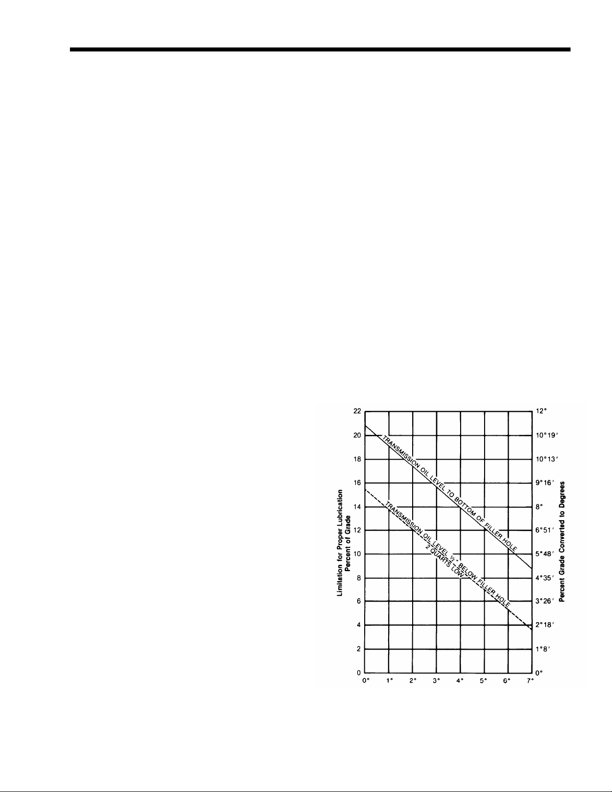
Proper Lubrication Levels
as Related to Transmission
Installation Angles
If the transmission operating angle is more
than 12 degrees, improper lubrication can occur. The operating angle is the transmission
mounting angle in the chassis plus the percent of upgrade (expressed in degrees).
The chart below illustrates the safe percent
of upgrade on which the transmission can be
used with various chassis mounting angles.
For example: if you have a 4 degree transmission mounting angle, then 8 degrees (or 14
percent of grade) is equal to the limit of 12
degrees. If you have a O degree mounting
angle, the transmission can be operated on a
12 degree (21 percent) grade.
Anytime the transmission operating angle of
12 degrees is exceeded for an extended
period of time the transmission should be
equipped with an oil pump or cooler kit to
insure proper lubrication.
Note on the chart the effect low oil levels
can have on safe operating angles. Allowing
the oil level to fall 1/2” below the filler plug
hole reduces the degree of grade by approximately 3 degrees (5.5 percent).
Proper Lubrication Levels are Essential!
Transmission Oil Coolers are:
Recommended
— With engines of 350 H.P. and above
with overdrive transmissions
Required
— With engines 399 H.P. and above with
overdrive transmissions and GCW’S
over 90,000 lbs.
— With engines 399 H.P. and above and
1400 Lbs.-Ft. or greater torque
— With engines 450 H.P. and above
With EP or Multipurpose Gear Oil
—
Mild EP gear oil and multipurpose gear oil are
not recommended when lubricant operating
temperatures are above 230°F (110). In addition, transmission oil coolers are not recommended with these gear oils since the oil
cooler materials may be attacked by these
gear oils. The lower temperature limit and oil
cooler restriction with these gear oils gener-
ally limit their success to milder applications.
Transmission Mounting Angle
Dotted line showing “2 Quarts Low” is for
reference only. Not recommended.
5
Page 11

Operation
In the following instructions, it is assumed that the driver is familiar with motor trucks and tractors, and that he can
coordinate the necessary movements of the shift lever and clutch pedal to make progressive and selective gear engagements in
either direction, up or down.
RT-I 110 and RT-12510 Operation
The RT-1 110 and RT-12510 have ten selective ratios, evenly and progressively spaced. Do not shift these transmissions as you would a conventional model with an auxiliary
or two-speed axle, because there is no split-shifting.
All shifts are made with one lever. The range control button
is used one time only during an upshift sequence, and one
time only during a downshift sequence.
Ten speeds obtained with one gear shift lever and range control button.
Since the transmissions consist of a five-speed front section
and a two-speed range section, the ten forward speeds are
obtained by using a five-speed shifting pattern twice – the
first time with the transmission in low range, and the
second time with the transmission in high range.
Shift pattern for the RT-1110 and R T-1251 O model transmissions.
Shift pattern for the R TO-1I10andRTO-12510 model transmissions.
10
Page 12

Upshifting
To get to high range
pull button
while in 5th speed,
then move lever
to 6th speed.
UP
Downshifting
To get to low range
push button DOWN
6th speed,
then move
lever to 5th speed.
speed.
10
9
8
RANGE
7
6
Upshifting
1. Move the gearshift lever to the neutral position.
2. Start the engine.
3. Wait for air system to reach normal line pressure.
4. Now look at the Range Control Button. If it is up push
it to the down position. (With the downward movement
of the button, the transmission will shift into low range.)
If the button
was down when the truck was last used,
the transmission is already in low range.
5. Now start the vehicle and shift progressively through 1st,
2nd, 3rd and 4th to 5th.
6. When in 5th and
ready for the next upward shift, PULL
the Range Control Button UP and move the lever to 6th
speed. As the lever
passes through the neutral position,
the transmission will automatically shift from low range
to high range.
7. With the transmission in high range, you may now shift
progressively through 7th, 8th and 9th to 10th.
Downshifting
1. When shifting down, move the lever from 10th through
each successive lower speed to 6th.
2. When in 6th, and ready for the next downward shift,
PUSH
the Range Control Button DOWN and move the
lever to 5th speed. As the lever
tral position,
the transmission will automatically shift
passes through the neu-
from high range to low range.
3. With the transmission in low range, shift downward
through each of the four remaining steps.
Driving tip: always start vehicle moving in first speed gear.
11
Page 13

General Instructions
Precautions
The shift through neutral is important only on the first
shift made after the control button is moved. Subsequent
shifts through neutral will not activate the automatic range
shift until the control button is moved once more.
When necessary to slow or
,.
.
stop the vehicle, shift
down through the individual short steps, allowing
the compression of the engine to slow the vehicle.
The life of chassis and
trailer brakes can thus be
prolonged.
When slowing the vehicle, it is also permissible to coast in
high range with the clutch disengaged. The shift to low
range, however, should not be made until it is necessary to
accelerate the vehicle once more.
Shifts will be fast and short as the gear shift lever stroke is
2% inches between positions. Conical engagement teeth are
standard on these transmissions,
gear clashing. Gear ratios average
thus helping to eliminate
26 per cent between ratio
steps.
To protect the transmission from abuse, the following precautions should be observed when shifting the vehicle:
1. Do not attempt to shift
from high range to low
range at high vehicle
speeds.
This downward
range shift should be made
only at a road speed equal
to that provided by fifth
or a
lower gear at governed
engine speed.
Do not attempt to make any range shifts either up or
2.
down when the vehicle is moving in reverse. Stay in the
range originally selected.
A mylar shift diagram is furnished with each transmission
should be installed on the vehicle dashboard. If it has been misplaced,
Service
Kalamazoo, Michigan.
new m
shift diagrams can be purchased from the
t, Transmission Division, Eaton Corporation,
Skip Shifting
After becoming proficient in shifting this transmission, the
operator may wish to skip some of the gear ratios to offset
a particular Operating condition.
Skip shifting can be
done when upshifting providing the range control
button is pulled up to the
high range position before
making any shift which
passes fifth speed.
Skip shifting is also possible during downshifting
providing the range control button is pushed
down to the low range
position before making any shift which passes sixth speed.
12
Page 14

RT-12515 and RTO-12515 Operation
The RT-125 15 transmission, like the RT-125 10, has a fivespeed front section and a two-speed auxiliary or range section which enables the driver to select 10 forward
speeds, evenly and progressively spaced. However, the
RT-125 15 models have an additional five speeds obtained
through a deep reduction gear (hole-gear).
The 10 ratios in high and low range are obtained with one
lever and a range control button. The five speeds in deep
reduction are obtained with the same gearshift lever and a
Deep Reduction Valve which controls the “IN” or “OUT”
position of the reduction gear.
The five ratios in deep reduction are evenly and progressively spaced. These five ratios, however, overlap the low range
ratios and are not progressively spaced in relation to the
low range ratios.
The deep reduction gear should be used only when
SHIFTING DIAGRAM OF THE RT-12515
Fifteen speeds obtained with one gear lever, a
Range Control Button and a Deep Reduction Valve.
(Ratios shown with each gear shift lever position.)
operating under adverse conditions and only when the
transmission is in LOW RANGE with the control valve button down. Never move the Deep Reduction Valve to “IN”
when in high range. When the valve is moved to “IN” the
reduction ratios will be engaged regardless of the position
of the Range Control Button.
The RTO-12515 is operated in the same manner as the
RT-125 15 except for the reversal of the 4th and 5th gearshift lever positions.
Upshift Through Low and High Range
Shift upward through the 10 speeds of low and high range
in the same manner as upshifting the RT-12510 or RTO12510 model transmissions. MAKE SURE THE DEEP REDUCTION VALVE IS IN THE “OUT” POSITION AT ALL
TIMES during the low and high range shifts.
SHIFTING DIAGRAM OF THE RTO-12515
Fifteen speeds obtained with one gear shift lever, a
Range Control Button and a Deep Reduction Valve.
(Ratios shown with each gear shift lever position.)
One through 10 speeds . . .
and Deep Reduction gear disengaged.
. . .
Five additional ratios . . .
gaged.
with Range Control Button
with Deep Reduction gear en-
One through 10 speeds . . .
and Deep Reduction gear disengaged.
. . .
Five additional ratios
engaged.
13
. . .
with Range Control Button
with Deep Reduction gear
Page 15

SUGGESTED SHIFT PATTERN FOR THE RT-12515 THROUGH REDUCTION AND LOW AND HIGH RANGE
(Ratios shown next to each gear shift lever position)
Shift 1 through 5 with range
Move deep
Pull range control button up while in 5th of low range . . . and shift
reduction valve to “OUT”
control button down and deep reduction valve to “IN”
while in 5th reduction . . .
and shift through 4th &
6th through 10th
5th of low range
Upshift Through Deep Reduction,
Low and High Range
There are several patterns of upshifting depending upon 2.
conditions of road and load. Check gear ratios to determine
the best ratio split for your particular condition. The following instructions are recommended for average condi- 3.
tions:
1. With the gearshift lever in neutral, the engine started and 4.
air system pressure normal, PUSH THE RANGE CONTROL BUTTON TO THE DOWN POSITION.
14
Move the Deep Reduction Valve
to the “IN” position to
engage the deep reduction gear.
Start the vehicle and shift progressively from 1st through
5th of the shift pattern.
When in 5th speed position and ready for the next upshift, move the Deep Reduction Valve to the “OUT”
position and shift to the 4th speed position, thus shifting
Page 16

out of the reduction ratios to low range ratios. Torque
will keep the reduction gear engaged until the shift out
of fifth position is made. Remember, although
the shift
lever is moved from 5th to 4th, this is an upshift and
accelerator must be moved accordingly. There will be no
automatic range shift as the transmission already is in
low range.
5. Shift through the 4th and 5th speed positions of low
range.
6. When ready for the next upshift, pull the Range Control
Button up while in the 5th speed position of low range
and shift the lever to the first speed position of the shift
pattern. As the lever passes through neutral, the transmission will automatically shift from low to high range.
7. Shift progressively upward from 6th through 10th in
high range.
NOTE: The above is for the RT-12515. RTO12515 shift from reduction to low range would differ,
according to the ratios desired.
Important Procedures
1. When making the shift from a reduction ratio to a low
range ratio, move the Deep Reduction Valve from “IN”
to “OUT” IMMEDIATELY BEFORE making the shift.
This is not a pre-select valve and only torque will hold
the reduction gear after the lever is moved to “OUT”;
the shift cylinder will make the shift by air as soon as
torque is released.
2. Never move the Deep Reduction Valve lever with the
transmission in high range (range control button up) as
the reduction gear bypasses both the low and high range
sections, regardless of the position of the range control
button.
3. When downshifting it should not be necessary to shift
into deep reduction ratios. The reduction in low range
should be sufficient in most operating conditions.
All instructions pertaining to the Range Control Button, skip shifting and general precautions of the ten-speed shift pattern of
the RT-1 110 and RT-1251O apply as well to the RT-12515.
15
Page 17

Air Systems
Range Shift Air System – All Models
This system consists of an air filter, regulator, air valve,
control valve, shift cylinder, fittings and connecting lines.
See Illustration A.
Constant regulated air is supplied to the bottom port of the
air valve and to the “IN” port of the control valve. With the
control button down, air passes through the control valve
and to the end port of the air valve. This permits air from
the constant supply to flow through the low range port in
bottom, side cap of air valve and to the shift cylinder air
port. Air on this port moves the shift piston and bar to the
rear to engage the low range gear.
With the control button up the control valve is closed and
air is removed from end port of air valve. This permits air
from the constant supply to flow through the high range
port in rear, side cap of air valve and to the shift cylinder
cover air port. Air on this port moves the shift piston and
bar forward to engage the high range gear.
When the control button is moved from one position to
another, air from the previously charged line exhausts
through the breather in air valve.
On some transmissions the air valve may be installed in a
180° position from that shown in Illustration A. The porting on these models, however, remains the same. The bottom port in the side cap is always the low range port.
16
Page 18

Hole-Gear Air System – RT-12515 Series
This system uses the air filter and regulator of the range
shift air system, plus a Deep Reduction Valve, mounted in
the vehicle’s cab, and a hole- gearshift cylinder. See Illustration B.
Constant regulated air is supplied to the end port of the
deep reduction valve and to the air port in the lower, right
side of the hole -gearshift cylinder cover.
The deep reduction valve lever has two positions, “IN” and
“OUT”. With the lever moved to the “IN” position the
valve is off. Thus, constant air channeled through the shift
cylinder and cover to the front of the shift piston moves
the piston and shift bar to the rear to engage the hole-gear.
As the hole-gear is engaged the range mainshaft is disengaged from the output shaft, removing the low and high
range sections from the power flow.
With the deep reduction valve lever moved to the “OUT”
position air flows out the side port of the valve and to the
air port near the center of the hole -gearshift cylinder cover.
This air, pushing against a larger piston area than the constant air supply, moves the shift piston and bar forward to
disengage the hole-gear. As the hole-gear is disengaged, the
range mainshaft is engaged to the output shaft, permitting
use of the low and high range sections.
B. Hook-up diagram and troubleshooting checkpoints for
the hole-gear air system.
17
Page 19
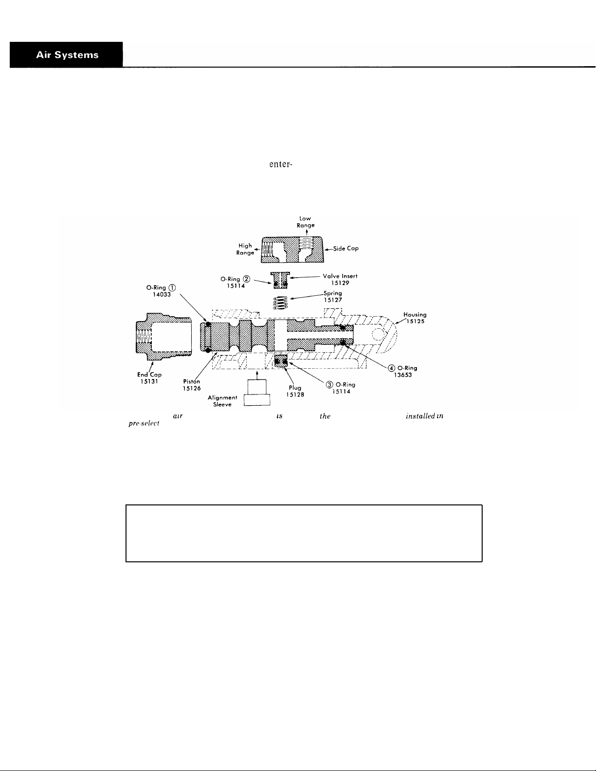
Air Valve Operation
With the range control button up the control valve shuts off
the air supply to the end cap. Thus, the constant air
ing at the constant supply port forces the piston to the rear.
The constant air also flows through a channel in the center
of the piston and to an external port which is aligned with
the high range port of the air valve.
C. Exploded view of value. The alignment sleeve not part of assembly, but must be housing for
proper
operation.
With the control button down the control valve opens and
supplies air to the end cap. Since the piston area is larger on
this end of the piston, it is forced in the opposite direction.
The external air port in the piston is now aligned with the
low range port of the air valve.
The four O-rings are indicated by circled numbers. If any of these are defective, there will be a constant air leak out of the
exhaust on the air valve. In normal operation, exhaust will occur only for an instant as the range shift is made. The following
chart is to be used as a guide to determine defective O-rings.
Defective
O-Rings
1
2or3
4
Constant leak through exhaust in low range only.
Constant leak through exhaust in both ranges.
Constant leak through exhaust in high range; steady but low volume
RESULT
leak through exhaust in low range.
To Disassemble Air Valve
Turn out the two capscrews and remove the side cap 4.
1.
from valve body.
Remove the valve insert from piston and remove O ring 5.
2.
from the valve insert.
Remove the spring from piston.
3.
Turn end cap from valve body and withdraw piston from
bore.
Remove the two O-rings from piston.
Remove the nylon plug from piston and remove O-ring
6.
from plug.
18
Page 20

Air Valve Pre-Selection
An actuating pin protruding from the shifting bar housing
prevents the actuating piston in the air valve from moving
while the gearshift lever is in a gear position and releases the
SLEEVE
D, Cross-section actuating pin and plunger assembly.
piston when the lever is moved to or through neutral. See
detailed installation of air valve for installation precaution
concerning the actuating pin.
Air Regulator
The air regulator is not serviceable. If defective replace the
air regulator unit. Reading at output of air regulator should
be 57.5 to 62.5 psi.
Air Filter & Regulator Assembly
19
Page 21

E. Exploded of control value. The
air to cap of air ualoe.
“IN’’port
constant
If the O-rings or parts in the control valve are defective
there will be a constant air leak out the exhaust located on
bottom of control valve.
A
defective insert valve O-ring will result in a constant leak
through exhaust in both ranges and valve will not make
range shifts.
A defective housing O-ring will result in a constant, low
volume leak through exhaust in low range only.
If the slide is assembled backwards, there will be a constant
leak through exhaust in high range. When installing slide in
control valve make sure that slot in slide faces the outlet
part.
To Disassemble the Control Valve
1. Remove the four screws to separate front and rear housings.
supply. The “OUTLET” port connected by O. L).
2.
Remove the slide and the two position balls and springs.
Remove the flat metal seal from outlet side and remove
3.
the O-ring from body.
Remove the valve insert from front housing and re-
4.
move the O-ring from valve insert.
Remove the wave washer installed under valve insert.
5.
Remove
6.
Punch out roll pin and remove control button from
7.
slide.
Qty.
2
1
1
1
1
the two felt wipers from valve housings.
Air Valve O-Ring sizes, Ill. C
Location
Valve Insert and Plug
Piston
Piston
Control Valve O-Ring sizes, Ill. E
Valve Insert .301
Housing .375
ID Width
.208
.549
.364
.070
.103
.070
.070
.062
20
Page 22

Trouble Shooting
Range Shift Air System All Models
The following checks are to be made with normal vehicle air pressure but with the engine off. Refer to Illustration A for
check points.
Incorrect Hook-Up
1.
With normal vehicle air pressure and gearshift lever in
the neutral position, move the control button up and
down, from one range to another.
If lines are crossed between the control valve and the
a.
air valve on transmission, there will be a steady flow
of air from the top exhaust in control valve if button
is held in the up position.
If lines are crossed between the air valve on transmis-
b
sion and the air or shift cylinder, the transmission
gearing will not correspond with the button position.
Low range, down position of button, will result in
high range gear engagement in the transmission and
vice versa.
Air Leaks
2.
With normal vehicle air pressure and gearshift lever in
the neutral position, coat all air lines and fittings with
soapy water and check for leaks, moving control button
to
both positions.
If there is a steady leak out exhaust of control valve,
a.
there are defective parts or O-rings in the control
valve.
If there is a steady leak out breather on air valve;
b.
there is a defective O-ring in the air valve; or there is a
leak past O-rings on the shift cylinder piston (see Ill.
F, Check Point E).
If transmission fails to shift into low range or is slow
c.
to make the shift and the transmission case is pressurized, see Ill. F, Check Point E.
Tighten all loose connections and replace defective
d.
parts or O-rings.
3.
Air Regulator, Check Point A
With normal line pressure and gearshift lever in neutral,
check exhaust port on side of air regulator. There should
be no leak from this port.
If there is a steady leak from exhaust port, this indicates
a defective air regulator and should be replaced.
Cut off the vehicle air pressure and install air gauge in
line at output port of air regulator. Bring vehicle air
pressure to normal. Regulated pressure should be 57.5 to
62.5 psi.
If correct pressure readings are not obtained, replace
regulator.
4.
Control Valve, Check Point B
With the gearshift lever in neutral, pull the control but-
ton up to high range and disconnect the 1/8" black
nylon air line at air valve.
a,
When control button is pushed down a steady blast of
air should flow from the disconnected line. Air will
shut off when button is pulled up. This indicates that
control valve is operating correctly. Reconnect air
line. If control valve does not operate correctly,
check for leaks, restrictions and defective O-rings.
5.
High Range, Check Point C
With the gearshift lever in neutral, push the control button down and disconnect the high range air line from the
shift cylinder cover.
a.
Pull the control button up. There should be a steady
flow of air from the high range air line. Push button
down to shut off air.
b.
Make sure vehicle engine is off and move the gearshift
lever to a gear position. Pull the button up; there
should be no air at high range line. Move the gearshift
lever to neutral; there should now be a steady flow of
air from the high range line. Push button down to
shut off air and reconnect line.
c.
If air system operated incorrectly, this indicates that
air valve is defective or that actuating parts in shifting
bar housing are jammed or defective.
21
Page 23

6. Low Range, Check Point D
With the gearshift lever in neutral, pull the control button up and disconnect the low range air line at shift
cylinder.
a. Repeat procedure under Check Point C, reversing the
position of the control button in order to check the
low range operation.
7. Range Shift Cylinder – Check Point E
If any of the seals in the range shift cylinder are defective the range shift will be affected. The degree of lost
air, of course, will govern the degree of failure, from
slow shift to complete failure to shift.
Refer to Illustration F for location of seals. Make sure
cylinder bore is clean to prevent damage to piston seal.
Use only a very light amount of shellac or Permatex on
cover gasket to prevent clogging cylinder. Tighten cover
capscrews securely.
22
Page 24

Hole-Gear Air System
RT-12515 and RTO-12515 Transmissions
The following checks are to be made with normal vehicle air pressure but with the engine off. It is assumed air lines have been
checked for leaks and the air regulator has been checked and the correct reading obtained. Refer to Illustrat
on B for check
points.
1.
Air Input – Check Point F
With gearshift lever in neutral and normal vehicle air
pressure, loosen the connection at input (end port) of
the deep reduction valve until it can be determined that
there is a constant flow of air at this point. Reconnect
line.
If there is no air at this point, there is a restriction in the
line between the deep reduction valve and air valve. Also
Refer to Illustration
Leak at seal A . . . .
Leak at seal B....
G, for location of seals
Failure to engage hole-gear; pressurizing of transmission; hole-gear
can be disengaged.
Failure to engage hole-gear; leak
from deep reduction valve exhaust
port when valve is “IN”.
check to make sure this line is connected to constant
supply.
Deep Reduction Valve – Check Point G
2.
G. Cutaway. Deep Reduction Shift Cylinder. (R T-12515 models)
With the deep reduction valve lever to “IN”, remove the
line from the deep reduction valve at the port in hole-
gearshift cylinder; there should be no air at this point.
Move the deep reduction valve lever to “OUT”. There
should now be a constant air flow from line. Move lever
to “IN” to shut off air. If the above conditions do not
exist, deep reduction valve is faulty or there is a restric-
tion in air line.
Hole-Gearshift Cylinder – Check Point H
3.
If any of the seals in the hole-gearshift cylinder are defective the hole-gearshift will be affected. The degree of
lost air, of course, will govern the degree of failure, from
slow shift to complete failure to shift.
23
Page 25

Preventive Maintenance Check Chart
CHECKS WITHOUT PARTIAL
DISASSEMBLY OF
CHASSIS OR CAB
1.
Air System and Connections
a. Check for leaks, worn air lines, loose connections and
capscrews. See Air Systems.
2.
Clutch Housing Mounting
a. Check all capscrews in bolt circle of clutch housing
for looseness. Tighten to recommended torque.
3.
Clutch Release Bearing
a. Remove hand hole cover and check radial and axial
clearance in release bearing.
b. Check relative position of thrust surface of release
bearing with thrust sleeve on push type clutches.
4.
Clutch Pedal Shaft and Bores
a. Pry upward on shafts to check wear.
b. If excessive movement is found, remove clutch release
mechanism and check bushings in bores and wear on
shafts.
8. Gearshift Lever Housing Assembly
Remove air lines at air valve and remove the gearshift
a.
lever housing assembly from transmission.
b.
Check tension spring and washer for set and wear.
c.
Check the gearshift lever pivot pin and pivot pin slot
for wear.
Check bottom end of gearshift lever for wear and
d.
check slot of yokes and blocks in shift bar housing
for wear at contact points with shift lever.
CHECKS WITH DRIVE LINE
DROPPED
9. Universal Joint Companion Flange Nut
a. Check for tightness. Tighten to recommended torque.
CHECKS WITH UNIVERSAL JOINT
COMPANION FLANGE REMOVED
10. Splines on Output Shaft
a. Check for wear from movement and chucking action
of the universal joint companion flange.
5.
Gear Lubricant
a. Change at specified service intervals.
b. Use only gear oils as recommended. See Lubrication
section.
Filler and Drain Plugs
6.
a. Remove filler plug and check level of lubricant at
specified intervals.
Tighten filler and drain plugs
securely.
7.
Gear Shift Lever
a. Check for looseness and free play in housing. If lever
is loose in housing, proceed with Check No. 8.
11. Mainshaft Rear Bearing Cover
a. Check oil seal for wear.
12. Output Shaft
a. Pry upward against output shaft to check radial clear
ante in mainshaft rear bearing.
24
Page 26

-
. . .
25
Page 27

Special Procedure For
Clutch (Input) Shaft
In some cases in field repair it may benecessary to replace
only the input shaft due to clutch wear on the splines.
In these instances the input shaft can be removed without
disassembling the transmission other than removing the
shifting bar housing. Removal of the clutch housing is optional. Following is the detailed procedure:
Disassembly
Remove gearshift lever housing and shift bar housing
1.
from transmission.
Remove the front bearing cover.
2.
Engage the mainshaft sliding clutches in two gears and
3.
remove the drive gear bearing nut.
4.
Move the drive gear assembly as far forward as possible
and remove the drive gear bearing.
5.
Remove the washer from input shaft.
From the front, remove the snap ring from ID of drive
6.
gear.
7.
Pull the input shaft forward and from splines of drive
gear.
2.
Install snap ring in ID of drive gear.
Install washer on shaft.
3.
Move the fourth-fifth speed sliding clutch gear forward
4.
to contact end of input shaft
hub of drive gear. Block
between rear of sliding clutch and front of the fourth
speed gear. When installing bearing this will hold input
shaft in position to seat the bearing properly.
Install drive gear bearing on shaft and into case bore,
5.
making sure blocking remains in place.
Remove blocking from mainshaft and install the drive
6.
gear bearing nut, left-hand thread. Use Loctite sealant on
threads of nut and shaft.
Peen nut into milled slots in shaft.
7.
Re-install front bearing cover, shifting bar housing and
8.
gearshift lever housing.
NOTE: 7%e above instructions are for changing the input shaft only. To change the drive gear, complete disassembly of the fron t section must be made.
Reassembly
1. Install new input shaft into splines of drive gear just far
enough to expose snap ring groove in ID of drive gear.
Make sure
the input shaft.
that the bushing is installed in the pocket
26
Page 28

General Precautions for Disassembly
IMPORTANT: Read this section before starting
the detailed disassembly procedures.
[t is assumed in the detailed disassembly instructions that
the lubricant has been drained
necessary linkage and air lines removed and the transmission has been removed from the chassis. Removal of the
gearshift lever housing assembly is included in the detailed
instructions; however, this assembly must also be removed
from transmission before removing unit from vehicle.
On
RT-12515 and RTO-I2515 models, air lines from the
hole-gear switch in cab must be disconnected at the transmission before removing unit from vehicle.
Follow
each procedure closely in each section, making use
of both the text and pictures.
BEARINGS Carefully wash and relubricate all bear-
1.
ings as removed and protectively wrap until ready for
use. Remove all bearings with pullers designed for this
purpose
punch.
-- do not remove bearings with hammer and
from the transmission, the
2.
SNAP RINGS Remove snap rings with pliers designed
for this purpose. Rings removed in this manner can be
reused.
INPUT SHAFT The clutch
3.
moved on most models without removing the countershaft, mainshaft or drive gear. See page 26.
4.
CLEANLINESS Provide a clean place to work. It is
important that no dirt or foreign material enters the unit
during repairs.
fully cleaned before starting the disassembly. Dirt is
abrasive and can damage highly polished parts such as
bearings, sleeves and bushings.
or input shaft can be re-
The outside of the unit should be care-
5.
WHEN DRIVING Apply force to shafts, housings,
etc., with restraint. Movement of some parts is re-
stricted.
stops solidly. Use soft hammers and bars for all disassembly work.
27
Do not apply force after the part being driven
Page 29

1. Shifting Controls.
28
Page 30

Removal of the Deep Reduction Shift Air
A.
1. Remove the 1/4" ID air line between the deep reduction
shift cylinder and the tee fitting forward of the filter /
regulator assembly.
System D
RT-12515 Series
B. Removal of the Range Shift Air System
1. Disconnect the black and white 1/8" OD air line at the
air valve on the side of the transmission.
NOTE: The gear shift lever housing, range control valve
and lines may now be removed as a unit by turning out
the four capscrews at the base of the gear shift lever
housing.
2. Disconnect the black and white 1/8" O D air line at the
range control valve on the shift lever.
29
Page 31

Disassembly - Air System
Removal of the Range Shift Air System - continued
B.
5. Remove the hose clamp and disconnect the two 1/4" ID
air lines between
cylinder.
air valve and the range shift
Loosen the clamp holding the range control valve to the
lever.
Turn the shift ball from the top of the lever and remove
the valve, air lines, sheathing and o-rings. For further
disassembly of the range control valve, refer to page 20.
NOTE: For ease of reassembly, it is advisable to tag the
1/4" I.D. air lines as to their proper locations during re-
moval.
6. Disconnect the 1/4" ID air line between the air valve and
the filter/regulator assembly.
7. Remove the filter/regulator assembly from the auxiliary
housing. For further disassembly, refer to page 19.
30
Page 32

8. Turn out the four capscrews and remove the air valve
from the side of the front case. For further disassembly
of the air valve, refer to page 18.
10. Remove the spring and plunger from the bore in the
adaptor plate.
Remove the alignment sleeve
bore in the adaptor plate.
from the air valve or the
11. Turn out the two capscrews and two Allen head screws
and remove the adaptor plate from the side
31
of the case.
Page 33

c.
Removal and Disassembly of the Gear Shift Lever Housing
1. Turn out the four capscrews, jar lightly to break the
gasket seal and lift the gear shift lever assembly from the
shift bar housing.
4. Turn out the nut and remove the pivot pin from the
housing.
2. Remove the rubber dust cover from the lever and mount
the assembly in a vise by the housing. Free the tension
spring from the housing by inserting a large, heavybladed scredriver between the spring and the housing
and twisting. Force the spring from under the lugs in the
housing one coil at a time.
3. Remove the tension spring washer and lever from the
housing.
5. Remove the O-ring from the groove in the top of the
housing.
32
Page 34

D.
Removal and Disassembly of the Shift Bar Housing Assembly
1
Turn out the retaining capscrews, jar to break the gasket
seal and lift the shift bar housing from the case.
Mount the housing on its side in a vise with the exposed
3.
end of the actuating plunger facing up.
NOTE: Lay all parts on a clean bench in the order of
removal to facilitate reassembly. Bars not being removed
must be kept in the neutral position or interlock parts
will lock the bars, preventing removal.
2.
Remove the three tension springs and tip the housing to
remove the three tension balls located under the springs.
If necessary, remove the reverse light pin and plug from
the housing.
4. Cut the lockwire, turn out the lockscrews and remove
the oil trough from the side of the shift bar housing.
(Oil trough is optional )
33
Page 35

D.
Disassembly of the Shift Bar Housing - continued
5. Cut the lockwires, turn out the lockscrews and remove
the 4th-5th speed shift bar, block and yoke from the
housing.
7. CRemove the actuating plunger from the bore in the
housing.
6. Cut the lockwires, turn out the lockscrews and remove
the 2nd-3rd speed shift bar, block and yoke from the
housing. As the neutral notch clears the housing boss,
remove the interlock pin from the notch.
8. Cut the lockwire, turn out the lockscrew and remove the
lst-reverse speed shift bar and yoke.
34
Page 36

Shift Bar Housing
9. Remove the two interlock balls from the bore in the
housing boss.
35
Page 37

Companion Flange, auxiliary housing and Clutch Housing
II. Companion Flange, Auxiliary Housing
and Clutch Housing
A.
Removal of the Companion Flange or Yoke
1. Use a large breaker bar to remove the stop nut from the
output shaft.
B.
Removal of the Auxiliary Housing
NOTE: The RT-12515 auxiliary housing is shown in the
following steps, but the procedure is the same for the
RT-12510 and RT-1110 series transmissions.
2. Remove the stop nut washer and companion flange or
yoke from the splines of the output shaft.
1.
Turn out the capscrews and insert three puller screws in
the three tapped holes in the auxiliary housing flange.
Tighten the puller screws evenly to move the housing
approximately 1/2" to the rear.
36
2.
Attach a chain hoist to the auxiliary housing and move
the housing to the rear and off the front case dowel pins.
Page 38

Companion Flange, auxiliary housing and Clutch Housing
3. The transmission can also beset vertically to remove the
auxiliary housing. Block under the clutch housing to prevent damage to the input shaft and lift the auxiliary
housing upwards and from the front case.
c.
Removal of the Clutch Housing
1. If so equipped, remove
and/or upshift clutch brake and turn out nuts and bolts
securing the clutch housing to the front case.
the clutch release mechanism
2. Jar the clutch housing with a rubber mallet to break the
gasket seal and pull the housing straight forward and off
the studs and front bearing cover.
37
Page 39

III Front Section
A. Removal and Disassembly of the Auxiliary Drive Gear Assembly
1. Remove the mainshaft rear snap ring from the shaft.
Insert three puller screws in the tapped holes of the
3.
retainer ring and tighten evenly to remove the drive gear
assembly from the case bore.
2. Cut the lockwires and remove the lockscrews from the
bearing retainer ring.
38
4.
Remove the snap ring from the hub of the auxiliary
drive gear and press the retainer ring and bearing from
the gear.
Page 40

B.
Removal and Disassembly of the Left Reverse Idler Gear Assembly
Front Section
Move the mainshaft
1.
possible and remove
gear.
reverse gear as far to the rear as
the snap
-
ring from the ID of the
Use inside jaw pullers to remove the left auxiliary coun-
3.
tershaft front bearing from the reverse idler bore. The
right auxiliary countershaft front bearing may also be
removed at this time.
2. Move the reverse gear forward and against theist speed
gear, engaging the splines of the sliding clutch.
4. Remove the elastic stop nut and washer from the front
of the idler shaft.
39
Page 41

Disassembly of the Left Reverse Idler Gear Assembly - continued
B.
5. Remove the plug from the bore in the rear of the idler
shaft, insert an impact puller in the bore and remove the
shaft.
6. As the shaft is moved to the rear, remove the gear and
thrust washer from the case.
7. If necessary,
washer from the idler shaft.
remove the bearing inner race and rear
40
Page 42

Removal of the Countershaft Bearings
C.
1. Remove the snap ring from the rear of each countershaft.
4. Use a soft bar and mall to drive each countershaft as far
to the rear as possible. This will partially unseat the front
bearings.
2. From inside the case, use a mall and punch to drive the
countershaft rear bearings to the rear and from the case
bores and shafts.
NOTE: Removal procedures will most likely damage the
bearings and removal should not be attempted unless
replacement of the bearings is planned.
3. Cut the lockwires, turn out the lockscrews and remove
the two front bearing retaining plates.
5. Use a soft bar and mall on the rear of each countershaft
to drive each shaft as far forward as possible, unseating
the front bearings from the case bores. This will expose
the front bearing snap rings.
6. Use a bearing puller to remove the countershaft front
bearings.
41
Page 43

D.
Removal and Disassembly of the Mainshaft Assembly
1.
Block the right countershaft against the side of the case
and move the mainshaft as far to the rear as possible. Tip
the front of the mainshaft up and remove the assembly
from the case. Use caution as the reverse gear is free and
may fall from the shaft.
4. Remove the reverse gear spacer and pull the key to the
rear and from the mainshaft.
NOTE: When removing washers, spacers and gears, note
their location to facilitate reassembly of the mainshaft.
Keep washers and spacers with the gear from which they
were removed; there is one spacer and one washer for
each gear. The spacers have external splines and the
washers have internal splines.
2. Remove the 4th-5th speed sliding clutch.
3. Remove the snap ring from the rear of the mainshaft.
5. Work the washers, spacers and gears from the mainshaft.
It will be necessary to turn the washers, located in the
hubs of the gears,
shaft. If necessary, remove the snap ring from the hub of
each gear.
42
to align with the splines of the main-
Page 44

Removal and Disassembly of the Drive Gear Assembly
E.
1. Turn out the f rent bearing cover retaining capscrews and
from inside the case, use a soft bar and mall to move the
drive gear forward. This will force the front bearing
cover away from the case. Remove the front bearing
cover from the input shaft.
3. Move the drive gear assembly to the rear and into the
case, working past the countershaft gears. Remove the
drive gear assembly from the case.
2. Remove the snap ring from the drive gear bearing.
4. Relieve the drive gear bearing nut at the points where it
is peened into the milled slots of the shaft.
43
Page 45

E.
Disassembly of the Drive Gear Assembly - continued
5. Turn the bearing nut from the shaft. (LH thread)
6. Using the rear face of the drive gear as abase, press the
shaft through the gear to unseat the bearing from the
shaft. This will free the bearing, spacer and drive gear. If
necessary, remove the snap ring from the drive gear.
44
Page 46

F.
Removal and Disassembly of the Countershaft Assemblies
NOTE: Except for the number of teeth on the PTO
gear, the countershaft assemblies are identical and are
disassembled in the same manner.
1. Move the right countershaft to the rear as far as possible,
moving the front of the shaft to the inside of the case.
Lift the shaft from the case and repeat the procedure for
the left countershaft.
IMPORTANT: Never use the PTO gear as a pressing
base. The narrow thickness of this gear makes it susceptible to breakage.
3. Using the 2nd speed gear as a base, press the 2nd and 3rd
speed gears from the shaft. If necessary, use a hammer
and punch to remove
keyway.
2. Remove the spacer from the front of the countershaft
and using the 4th speed gear as a base, press the direct,
PTO and 4th speed gears from the shaft. This will re-
quire a press of at least 25 ton capacity. Use a safety
shield as a precaution.
G.
Removal and Disassembly of the Right Reverse Idler Gear Assembly
NOTE: The right reverse idler gear assembly is identical
to the left and is disassembled in the same manner.
45
the key from the countershaft
Page 47

IV. Auxiliary Section - RT-1110 Series
A.
Removal and Disassembly of the Range Shift Cylinder Assembly
1. For ease of disassemble y, mount the auxiliary section
upright in a vise. Turn out the capscrews and remove the
range shift cylinder cover.
2. Turn the nut from the end of the shift yoke bar.
4. Pull the yoke bar to the rear and out of the cylinder.
Remove the piston from the housing.
5. Remove the O-rings from the OD and ID of the piston.
3. Cut the lockwire and turn out the two yoke lockscrews.
6. Turn out the capscrews and remove the shift cylinder
housing from the auxiliary plate. Remove the shift yoke
from the sliding clutch gear of the synchronizer assembly. If necessary, remove the O-ring from the bore in the
cylinder housing.
46
Page 48

6. Removal of the Auxiliary Countershaft Assemblies
1. Turn out the capscrews and remove the two rear bearing
covers.
3. Use a soft bar and mall to drive the countershaft forward and from the rear bearings.
2. Remove the snap ring from the rear of each countershaft.
Removal and Disassembly of the Synchronizer Assembly
c.
1. Pull the synchronizer assembly from the splines of the
output shaft.
4. Remove the bearings from the bores by tapping lightly
and evenly to the rear with a soft bar.
NOTE: Check the bearing inner race on the front of
each countershaft t. If worn or damaged, remove with pry
bars or appropriate jaw pullers. If the auxiliary countershaft t f rent bearings are to be changed, these inner races
must be changed also.
Pull the direct (high range) cone synchronizer from the
2.,
pins of the low
assembly with a cloth as the three springs will be released at the blocker pin locations.
speed synchronizer ring. Cover the
47
Page 49

c.
Removal and Disassembly of the Synchronizer Assembly - continued
3. Remove the sliding clutch gear from the pins of the low
speed synchronizer.
D. Disassembly of the Low Speed Gear and Tailshaft Assembly
1. Use a soft bar and mall to drive the output shaft forward
and through the rear bearing.
2. Remove the bearing inner spacer from the shaft.
3. Using the front face of the low speed gear as a base,
press that shaft through the gear and bearing, freeing
bearing, washer and gear from shaft.
4. If necessary,
speed gear.
48
remove snap ring from the ID of the low
Page 50

5. Remove the splined spacer from the shaft.
7. Turn out the capscrews and remove the rear bearing
cover. If necessary, remove the oil seal from the cover.
8. Remove the bearing rear cone from the housing.
6. Remove the stepped washer from the shaft.
9. Remove the two bearing cups and outer spacer from the
housing bore.
49
Page 51

V Auxiliary Section - RT-12510 Series
A. Removal and Disassembly of the Range Shift Cylinder Assembly
1. For ease of disassembly, mount the auxiliary section upright in a vise.
range shift cylinder cover.
2. Turn the elastic stop nut from the end of the yoke bar.
Turn out the capscrews and remove the
3. Cut the lockwire and turn out the two yoke lockscrews.
4. Pull the bar forward and out of the shift cylinder. Remove the piston from the cylinder bore.
50
Page 52

5. Remove the O-rings from the OD and ID of the piston
and from the bore in the shift cylinder.
6. Turn out the capscrews and remove the shift cylinder
housing. Remove the shift yoke from the sliding clutch
gear of the synchronizer. If necessary, remove O-ring
from bore in cylinder housing.
51
Page 53

Removal of the Auxiliary Countershaft Assemblies
B.
1. Turn out the capscrews and remove the two rear bearing
covers.
2. Remove the snap ring from the rear of each countershaft.
3.
Use a soft bar and mall to drive the countershaft forward and from the rear bearings.
4.
Remove the bearings from bores by tapping lightly and
evenly to the rear with a soft bar.
NOTE: Check bearing inner races on front of each
countershaft. If worn or damaged, remove with pry bars
or appropriate jaw pullers.
52
Page 54

c.
Removal and Disassembly of the Synchronizer Assembly -- continued
3.
1. Pull the synchronizer assembly from the splines of the
output shaft.
Remove the sliding clutch gear from the pins of the low
speed synchronizer.
2. Pull the direct (high range) cone synchronizer from the
pins of the low speed synchronizer ring. Cover with a
cloth as the three springs will be released at the blocker
pin locations.
53
Page 55

D.
Removal and Disassembly of the Output Shaft Assembly
1. Use a soft bar and mall to drive the output shaft forward
and from the rear bearing assembly.
2. Remove the bearing inner spacer from the shaft.
3.
Using the front face of the low speed gear as a base,
press the shaft through the gear and bearing. Remove the
splined spacer from the hub of the gear.
4. Turn out the capscrews and remove the rear bearing
housing. If necessary, remove the oil seal from the housing. Remove the rear bearing cone from the housing.
54
Page 56

5. Remove the two bearing cups and outer spacer from the
auxiliary plate bore.
55
Page 57

VI Auxiliary Section - RT-12515 Series
A.
Removal and Disassembly of the Range Shift Cylinder Assembly
1. For ease of disassembly, mount the auxiliary section in a
vise in the upright position. Turn out the capscrews and
remove the range shift cylinder cover.
2. Turn the nut from the end of the yoke bar.
3. Cut the lockwire and turn out the two yoke lockscrews.
4. Push the yoke bar to the rear and from the housing.
Remove the piston from the bar.
56
Page 58

5. Remove the O-rings from the piston.
6. Turn out the capscrews and remove the shift cylinder
housing. If necessary, remove the O-ring from the ID of
the housing.
57
Page 59

Removal of the Auxiliary Countershaft Assemblies.
B.
1. Turn out the capscrews and remove the two rear bearing
covers.
4. Remove the bearings from the bores by tapping lightly
and evenly to the rear with a soft bar.
2. Remove the snap ring from the rear of each auxiliary
countershaft.
3. Use a soft bar and mall to drive the countershaft forward and from the rear bearings.
58
5. If necessary,
front of each countershaft with a puller or pry bars.
remove the bearing inner race from the
Page 60

Removal and Disassembly of the Synchronizer Assembly
c.
I
1. Pull the synchronizer assembly from the splines of the
output shaft.
3. Remove the sliding clutch from the pins of the low
speed synchronizer.
2. Pull the direct (high range) cone synchronizer from the
pins of the low speed synchronizer ring. Cover the
assembly with a cloth as the three springs will be released at the blocker pin locations.
59
Page 61

D. Removal of the Low Range Gear and Range Mainshaft Assembly
1. Remove the key from the keyway between the splines of
the range mainshaft.
2. Turn the washer located in the hub of the gear so that
the splines on the washer align with the splines on the
shaft.
3. Pull the gear and washer forward and off the splines of
the range mainshaft.
4. Remove the coupler from the shaft.
60
Page 62

5. Remove the snap ring from the output shaft quill.
7.
Remove the bearing from the shaft. If necessary, use an
inside jaw impact puller.
6. Use a puller or pry bars to pull the range mainshaft
forward and from the output shaft quill.
8. If necessary,
shaft. Check the bushing in the shaft and replace if
worn.
61
remove the snap ring from the OD of the
Page 63

E.
Removal and Disassembly of the Deep Reduction Shift Cylinder
1. Cut the lockwire and turn out the lockscrew from the
shift yoke.
4.
Remove the yoke bar from the housing. Remove the
O-ring from the bar.
2. Pull the shift yoke and clutch forward and from the
auxiliary housing.
3. Turn out the capscrews and remove the shift cylinder
cover.
5. Remove the cylinder housing from the auxiliary housing.
Remove the O-ring from the bore in the housing.
62
Page 64

F.
Removal and Disassembly of the Output Shaft Assembly
1. Turn out the capscrews and remove the rear bearing
housing. If necessary, remove the oil seal from the hous-
ing.
2. Remove the snap ring from the output shaft.
4. Use a soft bar and mall to drive the output shaft forward
and from the auxiliary housing.
5. Use the deep reduction gear as a base to press the rear
bearing from the output shaft. This will free the gear,
washer, spacer and oil deflector.
3. Remove the speedometer drive gear or replacement
spacer from the-shaft.
6. Remove the two bearing cups and outer spacer from the
auxiliary housing bore.
63
Page 65

Inspection
Before reassembling the transmission, the individual parts should be carefully checked to eliminate those damaged from
previous service. This inspection procedure should be carefully followed to insure the maimum of wear life from the rebuilt
unit.
The cost of a new part is generally a small fraction of the total cost of downtime and labor, should the use of a questionable
part make additional repairs necessary before the next regularly scheduled overhaul.
Recommended inspection procedures are set forth in the following checklist:
A. Bearings
1. Wash all bearings in clean solvent. Check balls, rolls
and races for pits and spalled areas. Replace bearings
which are pitted or spalled.
Lubricate bearings
2.
which are spalled
or pitted and check
for axial and radial
clearances. Replace
bearings with excessive clearances.
3.
Check fits of bearings in case bores.
If outer races turn
freely in the bores,
the case should be
replaced.
B. Gears
1. Check operating gear teeth for pitting on the tooth
faces. Gears with pitted teeth should be replaced.
2. Check all engaging gear teeth. Gears with teeth worn,
tapered or reduced in length from clashing in shifting
should be replaced.
3. Check axial clearances of gears. Where excessive clearance is found, check gear snap ring, washer, spacer
and gear hub for excessive wear. Maintain .005 to
.012 axial clearance of mainshaft gears.
C. Splines
1. Check splines on all shafts for wear. If sliding clutch
gears, companion flange or clutch hub have worn into
the sides of the splines, the shafts in this condition
should be replaced.
D. Thrust Washers
1. Check surfaces of all
thrust washers. Washers
scored or reduced in thickness should be replaced.
E. Reverse Gear and Shaft
1. Check bearing sleeve for wear from action of roller
bearings.
. Check all gray iron parts
for cracks and breaks. Replace or repair parts found
to be damaged. Heavy
castings may be welded or
brazed providing the
cracks do not extend into
bearing bores or bolting
surfaces.
64
Page 66

G.
Clutch Release Parts
1. Check clutch release parts. Replace yokes worn at
cam surfaces and gearing
carrier worn at contact
pads.
2. Check pedal shafts. Replace those worn at bearing surfaces.
H. Shifting Bar Housing Assembly
1. Check yokes and blocks for wear at pads and lever
slot. Replace worn parts.
Check yokes for align-
2.
ment. Straighten those
which are sprung.
3.
Check lockscrews in yokes
and blocks. Tighten and
rewire those found loose.
If housing has been dis-
4.
mantled,
check neutral
notches of shifting bars for wear from interlock balls.
Bars indented at points adjacent to the neutral notch
should be replaced.
I. Gearshift Lever Housing Assembly
1. Check spring tension on shift lever. Replace tension
spring and washer if lever moves too freely.
2. If housing is dismantled, check pivot pin and corresponding slot in lever for wear. Replace both parts
if worn.
J. Bearing Covers
1. Check covers for wear from thrust of adjacent bearing. Replace covers worn and grooved from thrust of
bearing outer race.
2. Check bores of covers for wear. Replace those worn
oversize.
K. Oil Return Threads and Seals
1. Check oil return threads in front bearing cover. If
sealing action of threads has been destroyed by contact with input shaft, replace the cover.
2. Check oil seal in mainshaft rear bearing cover. If sealing action of lip has been destroyed, replace seal.
L. Synchronizers
1. Check high and low range synchronizers for burrs,
uneven and excessive wear at contact surface.
2. Check blocker pins for excessive wear or looseness.
3. Check synchronizer contact surfaces on the high and
low range gears for excessive wear.
4. Check contact surfaces of synchronizers for imbedded
metal particles.
65
Page 67

Torque Ratings
Recommended torque ratings, location and thread sizes of capscrews and nuts are listed below.Capscrew lengths are given for
reference purposes as a guide for installation at proper locations.
Correct torque application is extremely important to assure long transmission life and dependable performance. Over-tightening and under-tightening can result in a loose installation and. in many instances, eventually cause damage to transmission
gears, shafts or bearings. Do not torque capscrews dry.
CAPSCREWS
Thread Size
Location Qty. And Length Foot-Pounds
Air Valve
Air Valve Adapter Plate
Filter Bracket
4
2
2
1/4-20 x 1 -3/4 15-20
1/4-20 x 7/8
3/8-1 6 x 3/4
Torque Rating
15-20
20-25
18-23
*PTO Cover. small
Hole-Gear Shift Cylinder
6
4
3/8-16 x 3/4
5/16-18 xl-7/8
(12-15 with oil filter)
20-25
(RT-12515 only)
Aux. Drive Gear Retainer Ring
Range Shift Cylinder
Range Shift Cylinder Cover
Range Shift Cylinder Cover
(RT-I2515 only)
Shift Bar Housing
Gear Shift Lever Housing
Front Bearing Cover
Countershaft Rear Bearing Covers
Rear Plate to Case
Rear Plate to Case (RT-12515 only)
Mainshaft Rear Bearing Cover
C/S Front Bearing Retainers
16
18
18
6
4
4
4
3/8-16 x 1
3/8-16 x 1
3/8-16 x 1
3/8-16 x l-1/4
35-45
3/8-16 x 1-1/4
4
6
8
3/8-16 x 1-1/4
3/8-16 x 1-1/4
3/8-16 x 1-1/4
3/8-16 x 2
1
3/8-16 x 1-3/4
3/8-16 x 1-1/2
1
6
4
3/8-16 x 2
3/8-1 6 x 2-3/4
3/8-24 x 1
PTO Cover large
Clutch Housing to Case
*NOTE: Installing the capscrews with more than 23 ft-lbs. of torque will force the corners
case with resultant oil leakage.
8
2
2
66
7/16-14 x 1-1/4
l/2-13 x 1-1/2
l/2-13 x 3-l/2
50-65
90-100
of the PTO cover away from the
Page 68

Location
Qty .
NUTS
Torque Rating
Thread Size Foot-Pounds
Reverse Idler Shafts
Range Shift Piston
Clutch Housing to Case
Drive Gear
Companion Flange or Yoke
2
1
6
1
1
Location of Gaskets
Seat gasket with shellac on part to be installed. Use new
gaskets throughout when assembling transmission. Gaskets
are located between the following parts:
RT-1110, RT-12510
1. Gearshift lever housing and shift bar housing.
2. Shift bar housing and case.
3. Air valve adapter plate and case.
4. Air valve and adapter plate.
5. Clutch housing and case.
6. Front bearing cover and case.
7. Rear plate and case.
8. Mainshaft rear bearing cover and rear plate.
9. Auxiliary range shift cylinder cover and cylinder.
5/18-18
5/8-18
5/8-18
2-1/8-16
2-16
75-80
70-85
180-190
250-300
450-500
10. Auxiliary range shift cylinder and rear plate.
11. Right auxiliary countershaft rear bearing cover and rear
plate.
12. Left auxiliary countershaft rear bearing cover and rear
plate.
13. Large PTO cover and case.
14. Small PTO cover and case.
RT-12515
To the above list add:
1. Hole-gear shift cylinder cover and cylinder.
2. Hole-gear shift cylinder and case.
67
Page 69

General Precautions for Reassembly
IMPORTANT: Read this section before starting
the detailed reassembly procedures.
Make sure that interiors of case and housings are clean. It is
important that dirt be kept out of transmission during reassembly. Dirt is abrasive and can damage polished surfaces
of sleeves, bushings, bearings and washers. Use certain precautions, as listed below, during reassembly.
1
GASKETS -- Use new gaskets throughout the transmis-
sion as it is being rebuilt. Make sure all gaskets are in-
stalled, as omission of gasket
can result in oil leakage or
misalignment of bearing
covers.
See
"Location of
Gaskets" heading.
2
CAPSCREWS --To prevent oil leakage, use thread
sealant on all capscrews. See torque rating chart for
recommended torque.
O-RINGS - Lubricate all O-rings with Fuller part no.
3.
71206 or 71203 silicone lubricant.
6.
BEARINGS - Use of
recommended for the
flanged-end bearing drivers is
installation of bearings. These
drivers apply equal force to
both races of bearing, preventing damage to balls and
races and maintaining correct
bearing alignment with shaft
and bore. If tubular or sleeve
type driver is used, apply
force only to inner race.
7. UNIVERSAL JOINT COMPANION FLANGE - Pull the
companion flange tightly into place with the mainshaft
nut, using 450-500 foot-pounds of torque. Make sure the
INITIAL LUBRICATION Coat all thrust washers and
4.
splines of shafts with Lubriplate during installation to
provide initial lubrication, preventing scoring and galling.
5.
AXIAL CLEARANCES D Maintain original axial clear-
ances of mainshaft forward speed gears of .005" to
.01
.012".
Mainshaft reverse gear clearance is .005" to
2".
speedometer gear has been installed on yoke. If a speedometer gear is not used, a replacement spacer of the
same width must be used. Failure to pull the yoke or
flange tightly into place will permit the shaft to move
axially with resultant damage to rear bearing.
68
Page 70

REASSEMBLY INSTRUCTIONS
1. Auxiliary Section - RT-1110 Series
Reassembly of the Output Shaft and Rear Bearing Assembly
A.
1. Set the output shaft on bench with threaded end up and
install the stepped washer, large diameter down.
2. Install the splined spacer on the shaft, large diameter
down.
69
Page 71

A. Reassembly of the Output Shaft Assembly - continued
3. If previously removed, install the snap ring in the ID of
the low speed gear and install the gear on-the shaft, flat
side up.
4. Install the washer on the shaft.
6. Install the bearing inner spacer on the shaft.
7. Place the front cup of the rear bearing into the rear of
the housing bore, taper to the inside.
5. Install the front bearing cone on the shaft and against
the washer, taper up. Bearing is a matched set; make sure
correct cone for cup is used as indicated by markings.
NOTE: Heating of bearing cones for installation is recommended, provided the bearing is not heated over
275¡ F. Heat lamps are recommended as heat source.
8. Place the bearing outer spacer on the cup and place rear
cup on the spacer.
into the rear bore until the lip of the rear cup seats on
the housing.
70
Tap the two cups and spacer evenly
Page 72

B.
Reassembly and Installation of the Synchronizer Assembly
1. Place the larger low speed ring on the bench with the
pins upward and install the sliding clutch on the ring,
protruding clutching teeth down.
4.
Apply pressure to the direct ring while twisting counterclockwise to fully seat the direct ring on the low speed
ring pins.
2. Install the three springs in the direct ring.
3. Install the direct ring on the low speed ring pins, seating
the springs against the pins.
Set the synchronizer assembly on blocking approxi-
5.
mately 2" high on a bench large enough to accommodate the rear housing.
71
Page 73

c. Timing and Installation of the Auxiliary Countershafts and Output Shaft
1. On the small diameter low range gear of each countershaft, mark the tooth which is stamped with an "O".
IMPORTANT: Make sure that the bearing inner race has
been installed on the front of each auxiliary countershaft, large diameter towards the gear.
3. Install the output shaft assembly on the synchronizer,
meshing the splines of the shaft with the synchronizer.
2. Mark any two adjacent teeth on the low speed gear and 4. Place the countershaft into position against the output
then mark the two teeth directly opposite.
shaft, meshing the marked tooth on each countershaft
between a set of marked teeth on the low speed gear.
72
Page 74

5. Place the auxiliary housing down over the assembly, centering the countershafts in the rear bearing bores.
6. Heat the rear bearing cone and install it on the output
shaft, taper facing down.
8. Install the countershaft rear bearings on the shafts and in
the bores.
9. Install the snap ring in the rear of each countershaft.
7. If previously removed, install the oil seal in the rear
bearing cover and install the cover on the rear housing.
The capscrew with the brass washer is installed in the
hole intersecting the speedometer bore.
10. Install the rear bearing covers.
73
Page 75

D.
Installation of the Range Shift Cylinder Assembly
1. Install the housing in a vise in the upright position.
Install O-ring in the cylinder bore and secure the housing
to the rear housing with four capscrews. The air line
fitting is to the top.
2. Hold the shift yoke in position in the sliding clutch slot,
long hub to the front, and insert the yoke bar through
the yoke hub and shift cylinder threaded end first. Align
the slots in the shaft with the lockscrew bores in the
yoke hub. Insert two yoke lockscrews; tighten and wire
securely.
74
3. Install the O-rings in the OD and ID of the piston.
4.
Install the piston on the bar, flat side out, and secure
with the elastic stop nut.
Page 76

5. Install the shift cylinder cover with the air line fitting to
the top left.
75
Page 77

11. Auxiliary Section -
Reassembly of the Output Shaft and Rear Bearing Assembly
A.
RT-12510 Series
1. Place the output shaft on a bench with the threaded end
up and install the splined spacer on the shaft, large
diameter down.
2. Mark any two adjacent teeth on the low speed gear and
then mark the two teeth directly opposite.
76
Page 78

3. Install the low speed gear on the shaft with the clutching
teeth down and engaging the splines of the spacer.
5. Heat and install the front bearing cone on the shaft and
against the washer, taper facing up.
NOTE: Heating of the bearing will facilitate installation.
o
Do not heat the bearing over 275
F.
4. Install the washer on the shaft, flat surface down.
6. Install the bearing inner spacer on the shaft.
77
Page 79

A. Reassembly of the Output Shaft and Rear Bearing Assembly - continued
Place the bearing rear cup on the outer spacer and evenly
Place the front cup of the bearing assembly in the plate
7.
bore with the taper to the inside. Tap the cup evenly
into the plate with a soft bar.
9.
tap the cup into the plate bore until the lip of the cup
seats against the plate.
8. Place the outer spacer on the front cup and tap the
spacer evenly into the plate bore.
78
Place the rear plate over the output shaft assembly. Use
10.
caution to avoid moving the lip of the rear cup away
from the plate.
Page 80

11. Heat and install the rear bearing cone, taper to the
. .
reside.
NOTE: Heating of the bearing will facilitate installation. Do not heat the bearing over 275
o
F.
13.
Install the rear bearing housing over the output shaft
and against
equipped with a speedometer drive gear, the gear must
be installed on the output shaft prior to installation of
the rear bearing housing.
capscrew intersecting the speedometer drive gear bore.
the rear plate.
Use a brass washer on the
If the transmission is
12. If previously removed, install the oil seal in the rear
bearing housing,
79
Page 81

Reassembly and installation of the Synchronizer Assembly
B
1. Place the larger (low speed) brass synchronizer ring on a
bench with the pins facing up and install the sliding
clutch gear over the ring, protruding clutching teeth
down.
Apply pressure to the direct ring while twisting counter-
4.
clockwise to fully seat the direct ring on the low speed
ring pins.
2. Install the three springs in the direct ring.
3. Install the direct ring on the low speed ring pins, seating
the springs against the pins.
80
Mount the auxiliary plate in a vise in the upright posi-
5.
tion and install the synchronizer assembly on the output
shaft and into the reduction gear bore.
Page 82

Timing and Installation of the Auxiliary Countershaft Assemblies
1. On the small diameter low range gear of each countershaft, mark the tooth which is stamped with an "O".
. .
3. Install the snap ring on the rear of each countershaft.
2. Place one of the countershaft into position in the rear
plate, meshing the marked tooth on the countershaft
between two of the marked teeth on the low speed gear.
Use a soft bar to start the rear bearing on to the shaft
and into the case bore and use a bearing driver to complete the installation.
during bearing installation to make sure that the springs
do not pop out. Repeat the procedure for the remaining
countershaft.
NOTE: Make sure that the bearing inner race is installed
on the front of each auxiliary countershaft.
Check the synchronizer assembly
4. Install the countershaft rear bearing covers.
81
Page 83

Installation of the Range Shift Cylinder Assembly
D.
1. If previously removed, install the O-ring in the bore of
the cylinder housing and install the housing in the rear
plate bore, air fitting to the top right. Secure with the
four capscrews.
3. Insert the two yoke lockscrews; tighten and wire
securely.
2. Hold the shift yoke in position in the synchronizer sliding clutch gear with the long hub of the yoke to the rear
and insert the yoke bar through the yoke and cylinder
housing, aligning the notches in the bar with the yoke
lockscrew bores.
4. If previously removed, install the O-rings in the OD and
ID of the piston.
82
Page 84

5. Install the piston on the bar, flat side out and secure
with the elastic stop nut.
6. Install the shift cylinder cover on the housing with the
air fitting to the top left.
83
Page 85

IIl. Auxiliary Section -
A. Reassembly of the Output Shaft and Rear Bearing Assembly
RT-12515 Series
1. Place the output shaft on blocking with the threaded
end up. Use caution to avoid damage to the quill.
2. Install the splined spacer on the shaft.
84
Page 86

3. Mark any two adjacent teeth on the reduction gear and
then mark the two teeth directly opposite.
4. Install the reduction gear on the shaft and spacer with
the clutching teeth down.
5. Install the washer on the shaft and against the gear with
the side with the large groove facing up.
6. Install the oil deflector in the rear housing bore with the
cupped surface facing up. Use a large bearing driver to
drive the deflector down until the top surface of the
deflector is 2" below the machined surface of the output
shaft bore.
NOTE: If available, use two bearing outer spacers
stacked on top of each other to drive the oil deflector
into the bore. The deflector will be at the proper depth
when the top of the top spacer is flush with the
machined surface of the output shaft bore.
85
Page 87

Reassembly of the Output Shaft Assembly - continued
A.
7. Install the rear housing over the output shaft, allowing
the housing to rest on the reduction gear.
8. Heat the front bearing cone and install in the bore and
against the oil deflector with the cone surface facing up.
NOTE: Heating of the bearings will facilitate installa-
tion. Do not heat the bearings over 275
o
F.
9. Install the bearing inner spacer on the shaft and against
the front bearing cone.
10. Stack the two bearing cups and outer spacer in the
output shaft bore in the proper sequence. Make sure
that the front bearing cup taper matches the taper
direction of the front bearing cone.
86
Page 88

11. Tap the two cups and outer spacer lightly and evenly
into the case bore until the lip of the rear cup seats
against the machined surface. It will be necessary to
block under the rear housing slightly to permit the
output shaft assembly to move far enough.
13. Install the speedometer drive gear or replacement
spacer on the shaft and against the rear bearing cone.
12. Heat and install the rear bearing cone on the shaft and
in the rear cup, taper facing down.
14. Install the snap ring in the output shaft groove.
87
Page 89

A. Reassembly of the Output Shaft Assembly - continued
15.
If previously removed, install the oil seal in the rear
bearing housing with the side of the seal with the seam
facing into the housing.
16. Install the rear bearing housing on the auxiliary housing, making sure that the oil port in the auxiliary
housing aligns with the notch in the bearing housing.
Use a brass washer on the capscrew intersecting the
speedometer drive bore.
88
Page 90

Installation of the Range Mainshaft Assembly
B.
Install the clutch gear on the shaft, internal clutching
1.
teeth to the rear.
3. Install the range mainshaft on the output shaft quill.
2.
If previously removed, install the snap ring on the range
mainshaft. Check the bushing in the pocket of the main-
shaft for wear. Replace if defective.
4. Install the bearing on the quill and in the range mainshaft.
5. Secure the bearing with the snap ring.
89
Page 91

C. Reassembly and Installation of the Deep Reduction Shift Cylinder
1. Install an O-ring in the bore of the shift cylinder and
install the cylinder in the auxiliary housing with the air
channel to the right.
2. Install the yoke in the sliding clutch yoke slot with the
lockscrew hole facing up.
3. Install the O-ring in the yoke bar groove and push the
yoke bar forward and through the cylinder housing and
the shift yoke. Install the yoke Iockscrew; tighten and
wire securely.
4. Install the cylinder cover, aligning the air channel with
the channel in the cylinder housing.
90
Page 92

Installation of the Low Range Gear
D.
1. Install the coupler on the shaft, large diameter to the
rear.
3. Install the splined washer on the shaft and in the hub of
the gear. Turn the washer to lock the gear on the shaft.
NOTE: Splined washers with varying thicknesses are
available. Use the washer that provides the tightest fit in
the hub of the gear.
2. Mark any two adjacent teeth on the low range gear and
then mark the two teeth directly opposite. Install the
gear on the shaft and against the coupler with the dished
side facing to the front.
4. Install the key in the keyway, inserting the thick end
between the splines of the washer.
91
Page 93

Reassembly and Installation of the Synchronizer Assembly
E.
1. Place the larger low speed ring on the bench with the
pins upward and install the sliding clutch on the ring,
protruding clutching teeth down.
4. Apply pressure to the direct ring while twisting counterclockwise to fully seat the direct ring on the low speed
ring pins.
2. Install the three springs in the direct ring.
3. Install the direct ring on the low speed ring pins, seating
the springs against the pins.
5. Install the synchronizer assembly on the splines of the
output shaft and in the hub of the low speed gear.
92
Page 94

Timing and Installation of the Auxiliary Countershaft Assemblies
F.
1. Mark the tooth which is stamped with an "O" on each of
the three sets of gears on the auxiliary countershaft.
Place one of the countershaft into position in the case,
2.
meshing the marked teeth on the shaft between one of
the sets of marked teeth on each of the gears. Hold the
countershaft in position and use a soft bar to tap the
rear bearing on to the shaft and into the case bore. Use a
bearing driver to complete installation of the bearing.
Check the synchronizer during bearing installation to
make sure that the springs do not pop out. Repeat the
procedure to install the remaining countershaft.
3. Install the snap ring in the groove on the rear of each
countershaft.
4. Install the two rear bearing covers.
IMPORTANT: Make sure that the bearing inner race is
installed on the front of each countershaft.
93
Page 95

G.
Reassembly and Installation of the Range Shift Cylinder
1. Install the O-ring in the bore of the shift cylinder and
install the cylinder housing in the rear housing with the
air line fitting to the top.
2. Hold the shift yoke in position on the sliding clutch with
the long hub of
bar through the
in the bar with
Install the two
curely.
94
the yoke to the rear and insert the yoke
hub and shift cylinder, aligning the slots
the lockscrew bores in the yoke hub.
yoke lockscrews; tighten and wire se-
Page 96

3. Install the O-rings in the O D and ID of the piston.
5. Install the elastic stop nut on the bar and tighten securely.
4. Install the piston on the bar with the flat face out.
6. Install the cover on the shift cylinder with the air fitting
to the top left.
95
Page 97

IV. Front Section
A. Reassembly and Installation of the Right Reverse Idler Gear Assembly
NOTE: Check to make sure that the three magnetic
discs are solidly in place in the bottom of the case. These
can be installed with "3M Brand" adhesive, No. EC
1300.
.
1. Install the plug in the end of the reverse idler shaft and
install the idler gear washer on the shaft. If previously
removed, press the needle bearing into the bore of the
idler gear.
2. If previously removed, install the bearing inner race on
the shaft and insert the shaft, threaded end first into the
lower right wall of the case. As the shaft is moved for-
ward, install the reverse idler gear and thrust washer on
the shaft, making sure that the long hub on the idler gear
is facing towards the front of the case. The thrust washer
is installed between the front of the gear and the housing
boss.
96
Page 98

Seat the shaft securely in the bore, maliing sure that the
3.
needle bearings are positioned properly on the inner race
before moving the shaft forward. Secure the shaft with
the washer and elastic stop nut. Tighten to recommended torque.
4. Install the auxiliary countershaft front bearing in the
bore with a bearing driver.
97
Page 99

B.
Reassembly of the Countershaft Assemblies
NOTE: Except for the number of teeth on the PTO
gears, the countershaft are identical and assembled in
the same manner.
98
Page 100

1. If previously removed,
with the beveled end of the key away from the gears.
2. Press the 2nd speed gear on to the shaft with the long
hub of the gear facing down.
install the key in the keyway
4. Press the 4th speed or O/D gear onto the haft with the
long hub of the gear facing down.
3. Press the 3rd speed gear on to the shaft with the long
hub of the gear facing up.
5. Start the PTO gear on to the shaft with the rounded side
of the teeth facing up. Install the drive gear on the shaft
with the long hub facing up and press the PTO and drive
gears into position.
to the drive gear.
Install the spacer on the shaft next
99
 Loading...