

Page 1

Service Manual
Fuller Heavy Duty Transmissions
TRSM0580
October 2007
FRLO-14410C-T2
FRLO-15410C
FRLO-15410C-T2
FRLO-16410C
FRLO-16410C-T2
FRLOF-14410C
FRLOF-14410C-T2
FRLOF-15410C
FRLOF-15410C-T2
FRLOF-16410C
FRLOF-16410C-T2
Page 2

For parts or service call us
Pro Gear & Transmission, Inc.
1 (877) 776-4600
(407) 872-1901
parts@eprogear.com
906 W. Gore St.
Orlando, FL 32805
Page 3

Page 4
Warnings and Precautions
Introduction
Before starting a vehicle always be seated in the driver’s seat, place the transmission in neutral, set the parking brakes and
disengage the clutch.
Before working on a vehicle place the transmission in neutral, set the parking brakes and block the wheels.
Before towing the vehicle place the transmission in neutral, and lift the rear wheels off the ground, remove the axle shafts,
or disconnect the driveline to avoid damage to the transmission during towing.
The description and specifications contained in this service publication are current at the time of printing.
Eaton Corporation reserves the right to discontinue or modify its models and/or procedures and to change specifications at any
time without notice.
Any reference to brand name in this publication is made as an example of the types of tools and materials recommended for use
and should not be considered an endorsement. Equivalents may be used.
Always use genuine Eaton replacement parts.
This symbol is used throughout this
manual to call attention to procedures
where carelessness or failure to follow
specific instructions may result in
personal injury and/or component
damage.
Departure from the instructions, choice
of tools, materials and recommended
parts mentioned in this publication
may jeopardize the personal safety
of the service technician or vehicle
operator.
WARNING: Failure to follow indicated
procedures creates a high risk of personal
inj ury to t he servici ng technici an.
CAUTION: Failure to follow indicated
procedures may cause component
damage or malfunction.
IMPORTANT: Highly recommended
procedures for proper service of this unit.
Note: Additional service information not
cover ed in the servic e proce dures .
Service Procedure
Tip: Helpful removal and installation
procedures to aid in the service of this unit.
0
Page 5

Lightning Breakdown
Overview
Control Unit:
Electronic Control Unit:
ECU
Auxiliary Components:
Rear Bearing Cover
Control Unit:
Shift Knob
Control Unit:
Levers/Housings
& Isolators
Auxiliary Components:
Range Cylinder
Auxiliary Components:
Countershaft & Brgs
Front Section:
Reverse Idler
Auxiliary Components:
Mainshaft & Synchro
Air System:
Air Filter/Regulator
Front Section:
Case Assembly
Front Section:
Case Assembly
Auxiliary Components:
Splitter Cylinder
Front Section:
Integral Oil Cooler
Auxiliary Components:
Countershaft & Brgs
Front Section:
Countershaft Assy
106008-7-99
Control Unit:
Shift Shaft Assy
Front Section:
Reverse Idler
Front Section:
Countershaft Assy
Front Section:
Mainshaft Assy
Front Section:
Input Shaft & Drive Gear
Page 6

Table of Contents
Introduction
Warnings and Precautions ........................................... i
Overview ..................................................................... ii
General Service Practices and Part Inspection ............ 1
Purpose and Scope of Manual .................................... 5
Serial Tag Information and Model Nomenclature ........ 6
Torque Chart ............................................................... 9
Lubrication Information ............................................ 11
Recommended Tools ................................................14
Preventive Maintenance ............................................ 17
Oil Leak Inspection Process ...................................... 19
RTV Sealant Application Procedures ......................... 20
Power Flow ............................................................... 22
Gear Sets to be Timed ............................................... 27
Timing Procedures .................................................... 28
In-Vehicle Service Procedures
How to Remove the ECU ........................................... 31
How to Install the ECU .............................................. 32
How to Remove the Air Filter/Regulator .................... 33
How to Install the Air Filter/Regulator ....................... 34
How to Remove the Shift Knob ................................. 35
How to Install the Shift Knob .................................... 36
How to Remove the Gear Shift Lever/Remote
Shift Control ....................................................... 37
How to Install the Gear Shift Lever/Remote
Shift Control ....................................................... 38
How to Adjust the Remote Shift
Control (LRC Type) ............................................ 39
Neutral Switch Operation and Testing .......................41
How to Remove the Neutral Switch ........................... 42
How to Install the Neutral Switch .............................. 43
Reverse Switch Operation and Testing ...................... 44
How to Remove the Reverse Switch ......................... 45
How to Install the Reverse Switch ............................. 46
How to Remove the Shift Shaft Seal ......................... 47
How to Install the Shift Shaft Seal ............................. 48
How to Remove the Oil Seal -
Magnetic Speedometer ...................................... 50
How to Install the Output Shaft Oil Seal -
Magnetic Speedometer ...................................... 52
How to Remove the Output Bearing Cover ................ 54
How to Install the Output Bearing Cover ................... 56
How to Remove the Oil Cooler Fitting ....................... 58
How to Install the Oil Cooler Fitting ........................... 59
How to Remove the Auxiliary Countershaft
Bearing Cover .................................................... 60
How to Install the Auxiliary Countershaft
Bearing Cover .................................................... 61
How to Remove the Range Piston and
Range Bar O-Ring .............................................. 62
How to Install the Range Piston and
Range Bar O-Ring .............................................. 64
How to Remove the Splitter Piston ............................66
How to Install the Splitter Piston ...............................68
How to Remove the Clutch Access Cover ..................70
How to Install the Clutch Access Cover .....................71
Transmission Overhaul
Procedures-Bench Service
How to Disassemble the Gear Shift Lever ..................72
How to Assemble the Gear Shift Lever ......................74
How to Remove Output Yoke .....................................76
How to Remove the ECU ............................................77
How to Remove the Auxiliary Countershaft
Bearing Cover .....................................................78
How to Orient Transmission for Overhaul ..................79
How to Remove and Disassemble
Input Shaft and Oil Pump ...................................80
How to Remove and Disassemble Clutch
Housing/Front Cover ..........................................83
How to Remove Output Bearing Cover ......................85
How to Remove and Disassemble Front
Countershaft .......................................................86
How to Remove and Disassemble Mainshaft .............88
How to Remove and Disassemble the Shift Shaft ......91
How to Remove and Disassemble Reverse Idler ........94
How to Disassemble Splitter System .........................96
How to Remove and Disassemble Auxiliary
Countershaft .......................................................99
How to Remove and Disassemble Range System ....102
How to Remove and Disassemble Auxiliary
Mainshaft Assembly .........................................104
How to Remove Cooler and Fittings .........................106
How to Install Cooler and Fittings ............................107
How to Assemble and Install Auxiliary
Mainshaft Assembly .........................................108
How to Assemble and Install Range System ............111
How to Assemble and Install Auxiliary
Countershaft .....................................................114
How to Assemble Splitter System ............................117
How to Assemble and Install Reverse Idler ..............119
How to Assemble and Install the Shift Shaft ............121
How to Assemble and Install the Mainshaft .............123
How to Assemble and Install Front
Countershaft Assembly ....................................127
How to Install Output Bearing Cover ........................128
How to Assemble Clutch Housing / Front Cover ......129
How to Assemble Input Shaft and Oil Pump ............131
How to Install the Auxiliary Countershaft
Bearing Cover ...................................................134
How to Install the ECU .............................................135
How to Install Output Yoke ......................................136
M/S Endplay Shimming Procedure ..........................137
Page 7

Introduction
General Service Practices and Part Inspection
Safety
Always keep personal safety in mind when working on heavy truck transmissions. Do not ignore common sense.
Use appropriate safety equipment including:
• Safety glasses
• Safety shoes
• Gloves
• Proper transmission jack or lift with safety chains
• Guards and protective devices for presses, pullers, and drivers.
• Wheel chocks
Disassembly Tips
Cleanliness
The workplace must be clean to prevent dirt or other foreign material from contaminating the transmission during repairs. Dirt is
abrasive and can damage bearings. Eaton® recommends cleaning the outside of the unit before beginning disassembly.
Disassembling Assemblies
As components are removed from assemblies, lay the parts on a clean bench in the order in which they are removed. By laying the
parts out in order, they are less likely to be lost, and reassembly will be easier.
If bearings are to be reused, they must be removed with the proper bearing pullers, or they can be damaged. After removing bearings, carefully wash and lubricate them, and wrap them protectively in clean shop rags or towels until they are to be installed in
the transmission.
Input Shaft Removal
The input shaft assembly contains the transmission lube pump. The special procedure for removal and disassembly is located in
the “Transmission Overhaul Procedures” section.
Snap Ring Removal
Snap rings should be removed with snap ring pliers to avoid overstretching or deforming them.
Removing Parts Using Tools
Use care when removing parts with pullers or drivers to prevent damage to components. Never apply force to driven parts after
they stop solidly. Eaton® recommends using only soft hammers, soft bars, mauls, and the special tools indicated in the procedures for all disassembly work.
Marking Parts
To aid in reassembly and prevent unnecessary work, use a toolmaker’s die to mark the countershaft parts and rear bearing cover
to indicate position. Mark the countershaft parts, including the countershaft, gears, bearings, and shims, as “upper” or “lower”.
Mark the rear bearing cover to indicate the original position to the cover.
Parts Cleaning
WARNING
DO NOT USE GASOLINE TO CLEAN PARTS AS IT IS HIGHLY EXPLOSIVE.
Clean bearings and ground or polished parts in a cleaning solvent. To prevent corrosion, DO NOT clean ground or polished parts
in a hot solution tank, with water, or in alkaline solutions.
Housings can be cleaned with a cleaning solvent or in a hot solution tank with a mild alkaline solution. Dry and oil parts immedi-
ately after removal to prevent machined surfaces from corroding. Be careful cleaning aluminum parts; some cleaning solutions
may damage them.
1
Page 8

Introduction
Inspection
Gears
Inspect gear teeth for frosting, pitting, spalling, or other damage. Gears with frosting can usually be reused. Often, frosting on
gears heals with continuous use of the transmission and more serious pitting does not occur. Gears with light pitting can have
considerable life left and can also be reused. For gears with severe pitting, spalling, damage, or confirmed noise issues, the complete gear set (mainshaft gear and both countershaft gears) must be replaced.
Inspect the internal clutching teeth for excessive wear or rounding. Replace the gear and sliding clutch if necessary.
For additional information on wear of gear teeth, including full color photographs, refer to Eaton® Fuller® publication TRSM0913, Understanding Spur Gear Life.
Bearings
Inspect balls, rollers, races, and thrust surfaces for pitting, spalling, or discoloration. Check for excessive axial (up and down) or
radial (side-to- side) play. Replace the bearings as necessary.
Lubricate bearings with clean oil and rotate them to check for tightness or roughness. Replace the bearings as necessary.
Splined Shafts
Inspect splines for twisting, cracking, or wear. Replace splined shafts as necessary.
Note: Worn splines may indicate excessive torsional vibration. Make sure the vehicle system is corrected to prevent recurring
damage to the transmission.
Thrust Washers
Inspect thrust washers for wear or scoring, and replace them as necessary.
Snap Rings
Inspect snap rings for wear, twisting, stretching, or other damage. Snap rings must fit tightly in their grooves. Replace them as
necessary.
Housings
Inspect housings for cracks. Replace any cracked housings.
Inspect threaded holes for damage, and repair them as necessary.
Inspect bearing bores for wear. Light wear is acceptable. Housings with moderate to heavy wear in the bearing bores must be
replaced.
Introduction
Sliding Clutches
Inspect the clutching teeth for excessive wear or rounding. Light wear or rounding is acceptable. Replace clutches with moderate
to heavy tooth wear.
Inspect the yoke slots of the clutches for excessive wear. Replace worn clutches.
Range Synchronizer
Inspect the friction material for excessive wear of damage. Replace the synchronizer as necessary.
Inspect the blocker pins for excessive wear on the chamfered corners, looseness, or torsional vibration damage. If the blocker
pins are damaged, replace the range synchronizer.
Fit the low and high range synchronizers in their respective gears. Check for synchronizer bottoming on or in the gears. If bottoming occurs, replace the synchronizer assembly.
Inspect the synchronizer mating surface on the gears for signs of excessive heat. If signs of excessive heat are present, replace
the synchronizer assembly.
2
Page 9

Introduction
Clutch Housing
Inspect the pilot diameter where the clutch housing mates with the engine. Replace the clutch housing if the pilot diameter is
excessively worn.
Inspect the bushings for the clutch release linkage. Replace the bushings if they are worn.
O-Rings and Seals
Inspect o-rings and seals for wear, gouges, or permanent set, and replace them as necessary.
Shifting Mechanism
Inspect the shift yokes for excessive wear in the fork area. Light wear is acceptable. Replace any moderately or heavily worn shift
yokes.
Inspect the shift shaft for burrs or raised metal, and check the notches for excessive wear. Repair or replace parts as necessary.
Inspect the shift shaft, shift block, bias plate, shift key, detent key, plungers, and actuator parts for excessive wear or scoring.
Replace any of these parts as necessary.
Range Cylinder Assembly
Inspect the O-rings and piston seal for wear, damage, or permanent set, and replace them as necessary.
Inspect the piston bar, piston bores, and cylinder bores for wear or scoring. Replace any of these parts as necessary.
Shift Lever
Inspect the shift lever tip and spade pin groove for wear. Replace the parts as necessary.
Inspect the spade pin bore in the shift lever housing for excessive wear. Replace the housing as necessary
Input Shaft Seal
The input shaft seal is a lip type seal. Inspect the input shaft grooves and the inside of the front bearing cover for damage.
Replace any damaged parts.
Front Bearing Cover
If an input-shaft-mounted clutch brake is used on the transmission, inspect the clutch brake mating surface on the front bearing
cover for excessive wear. Replace the front bearing cover if the mating surface is excessively worn.
Gasket Surfaces
Inspect flanges and gasket surfaces for burrs, nicks, and scratches. Repair or replace parts as necessary.
Output Seal System
Inspect the output seal mating surface for wear, scratches, burrs, or other damage. Replace the seal surface if it is worn or damaged. Do not attempt to salvage the seal surfaces with crocus cloth, filing, etc.
For additional information, refer to the Eaton/Fuller® brochure TCSM-0912 “Seal Maintenance Guide”.
Reassembly Tips
Cleanliness
Make sure that parts are kept clean during reassembly. Prevent dirt or other foreign material from contaminating the transmisssion. Dirt is abrasive and can damage bearings.
Use lint-free shop rags when handling and cleaning parts. Too much lint inside the transmission can clog the oil pump pickup
screen.
Bearing Installation
To avoid damaging bearings, use a driver that contacts both the inner and outer race of the bearing. If the bearing balls/rollers or
bearing cage is damaged, the bearing must be replaced.
3
Page 10

Introduction
Capscrews
Make sure the threaded holes are clean and free of debris. If necessary, use a tap to clean the threads.
Make sure the capscrew threads are in good condition. If necessary, replace the capscrew.
Use a thread seal/locker compound on all capscrews. Use Eaton® Fuller® P/N 71295 thread sealant of equivalent.
Torque all capscrews to the recommended tightness.
Initial Lubrication
Unless stated specifically, lubricate all mating or sliding parts with transmission oil.
Lubricate all bearings with transmission oil.
Air System Lubrication
Lubricate all air system O-rings, seals, and cylinders with a light coating of silicone lubricant such as Eaton® Fuller® P/N 71203
(8fl.oz.) or P/N 71206 (0.14 fl.oz/).
Snap rings
Eaton® recommends using new snap rings for reassembly. A properly installed snap ring fits tightly in its groove and cannot be
easily rotated. All loose or overstretched snap rings must be replaced.
Introduction
4
Page 11

Introduction
Purpose and Scope of Manual
This manual is designed to provide detailed information necessary to service and repair the Eaton® Fuller® transmissions listed
on the front cover.
How to Use This Manual
The service procedures have been divided into two sections: In-Vehicle Service Procedures and Transmission Overhaul Procedures-Bench Service. In-Vehicle Service Procedures contain procedures that can be performed while the transmission is still
installed in the vehicle. Transmission Overhaul Procedures contain procedures that are performed after the transmission has
been removed from the vehicle.
The procedure sections are laid out with a general heading at the top outside edge of each page, along with more specific headings on the top left of the page and the specific procedures below. To find the information you need, first go to the section that
contains the correct procedure (In-Vehicle Service Procedures, Transmission Overhaul Procedures-Bench Service). Then look for
the correct heading at the top left of each page and follow the steps.
The sections located in front of the repair procedures are intended to give you information that is not included in the Service
Repair Procedures.
5
Page 12

Model Designations
Serial Tag Information and Model Nomenclature
Transmission model designation and other transmission identification information are stamped on the serial tag. To identify the
transmission model and serial number, locate the tag on the transmission and then locate the numbers as shown. Figure 1-1
below shows a tag and the tag location on the transmission.
When calling for service assistance or parts, have the model and serial numbers handy
Do not remove or destroy the transmission identification tag!
Model Designations
Model Number
The model number gives basic information about the transmission and is explained below. Use this number when calling for service assistance or replacement parts.
Serial Number
The serial number is the sequential identification number of the transmission. Before calling for service assistance, write the
number down.
Bill of material or Customer number
This number may be located below the model and serial numbers. It is a reference number used by Eaton®.
6
Page 13

Model Designations
Model Options
Torque Rating
The torque rating of the transmission specified in the model number is the input torque capacity in lb-ft. Various torque ratings
are available. For more information, call your Eaton Fuller regional sales and service office at 1-800-826-HELP (4357).
Shift System
Two types of shift systems are available for this transmission. Both are described and shown below.
Standard
The standard shift system has a gear shift lever opening located toward the rear of the transmission.
Forward Opening
The forward opening shift system has a gear shift lever opening located three inches closer to the front of the transmission than
the standard opening. This forward design allows greater flexibility in mounting the transmission and is indicated by an “F” in the
model number.
Standard Opening
Lubrication Pumps
Standard internal pump
Power Take Off (PTO) Usage
The 6 bolt openings are standard with the transmission. The PTO is mounted to the opening on either side and driven from the
countershaft gear.
Rear Mount
The thru-shaft PTO mounts are on the rear of the transmission. The thru-shaft PTO configuration is standard on the Lightning
transmission.
7
Forward Opening
Page 14

Contact Information for Lightning compatible PTO’s
Chelsea Power Take-Off Products
Dana Corporation
Model Designations
P.O. Box 321
Toledo, OH 43697-0321
Phone 1-800-729-3262
www.chelseapower.com
Muncie Power Products
P.O. Box 548
Muncie, IN 47308-0548
Phone 1-800-FOR-PTOS (1-800-367-7867) or 1-765-284-7721
www.munciepower.com
Model Designations
8
Page 15

Specifications
Torque Chart
The chart below lists the torque values for all the fasteners used on this model transmission. The torque values are also given in
the procedures any time a fastener must be tightened.
Table
Description Torque Value lb·ft
(Nm)
Shift Knob Jam Nut 35–45 (48–61) 1/2” X 13
Shift Lever Housing Capscrews 47–52 (63–70) M10 X 1.5
Remote Shift Control Mounting Capscrews
Clutch Release Yoke Capscrews 35–45 (48–61) 3/8” X 24
Clutch Release Adjusting Arm Capscrews
Clutch Housing Flange Capscrews See engine manufacturer recommendations
Rear Support Studs 60 Minimum (81) M16 X 2.0 Drive until bottomed (When using plugs apply
Rear Support Stud Nuts 170-190 (230-
Speed Sensor Retaining Capscrews 20-23 (27-31) M8 X 1.25
PTO Cover Capscrews/Studs 47-52 (63-70) M10 X 1.5
47–52 (63–70) M10 X 1.5
35–45 (48–61) 3/8” X 24
257)
Thread Size
X30MM
X30MM
for type, size, and assembly torque.
71206 sealant)
M16 X 1.5
X20MM
External Attachment Stud Nuts 20-23 (27-31) M8 X 1.25
Thermocouple Plug 47-52 (63-70) 1/2" NPT Use thread sealant
Oil Fill Plug 35-50 (47-67) 1 1/16" X 12 O-ring plug
Oil Drain Plug 35-50 (47-67) 1 1/16" X 12 O-ring plug
Air System Diagnostic Port Plugs 84-120 lb. in. 1/16"-27 Use thread sealant
Oil Level Site Glass 60-70 (81-95) 1 5/8" X 12 O-ring fitting
Air Filter/Regulator Capscrews 9-10 (12-14) M6 X 1.0 X
55MM
Neutral Switch 15-20 (20-27) M16 X 1.5 O-ring seal
Reverse Switch 15-20 (20-27) M16 X 1.5 O-ring seal
Splitter Detent Plug 15-20 (20-27) M16 X 1.5 O-ring seal
Output Shaft Nut 450-500 (610-
677)
Cooler Inlet & Outlet Fittings 40-50 (54-67) 7/8" UNF O-ring fitting
Main Case Breather 15-20 (20-27) 1/4" X 18 Use thread sealant
M48 X 2.0 Oil at yoke installation
9
Page 16

Table
Specifications
Description Torque Value lb·ft
(Nm)
ECU Breather 84-120 lb-in (9.5-
13.6)
Clutch Housing / Front Cover Capscrews
Front Bearing Cover Capscrews 35-40 (48-55) M10 X 1.5 X
Front Cover Oil Dam Plate Capscrew 20-23 (27-31) M8 X 1.25 X
Oil Trough Capscrews 20-23 (27-31) M8 X 1.25 X
Rear Countershaft Bearing CoverCapscrews
Output Shaft Bearing Cover Capscrews
Vehicle Wiring Harness Connector
Retaining Screw at ECU
ECU Mounting Capscrews 20-23 (27-31) M8 X 1.25 X
47-52 (63-70) M10 X 1.5
47-52 (63-70) M10 X 1.5 X
47-52 (63-70) M10 X 1.5 X
7-13 lb-in (.8-1.5) 10 X 24 Part of connector assembly
Thread Size
1/8" X 27 Use thread sealant
35MM
12MM
12MM
30MM
45MM
70MM
Specifications
ECU Position Sensor Capscrews 22-28 lb-in (2.4-
3.2)
ECU Solenoid Pack Capscrews 22-28 lb-in (2.4-
3.2)
Range Piston Retaining Nut 25-35 (34-47) M10 X 1.5
Eccentric Pump Setscrew 3 Maximum (4)
maximum
Shift Shaft Neutral Detent Plunger
Plug
Shift Shaft Reverse Bias Detent Plug 15-20 (20-27) M18 X 1.75
Reverse Idler Retaining Capscrews 47-52 (63-70) M10 X 1.5 X
Cooler Retaining Capscrews 20-23 (27-31) M8 X 1.25 X
15-20 (20-27) M16 X 1.5
M4 X.75 X
16MM
M4 X.75 X
16MM
M4 X.75 X
25MM
30MM
12MM
Drive until the setscrew bottoms into pump
eccentric
10
Page 17
Lubrication Information
Lubrication Information
Proper lubrication procedures are the key to a good all-around maintenance program.
Eaton® Fuller® Transmissions are designed so internal parts operate in an oil circulating bath created by the motion of the gears
and shafts.
All parts will be properly lubricated if these procedures are closely followed:
a. Maintain oil level and inspect regularly.
b. Follow maintenance interval chart.
c. Use the correct grade and type of oil.
d. Buy from a reputable dealer.
Maintain Proper Oil Level
Make sure the oil is level with the filler opening. Being able to reach the oil with your finger does not mean the oil is at The proper
level. (One inch of oil level is about one gallon of oil.)
IMPORTANT
When adding oil, never mix engine and gear oils in the same transmission.
Hole
Improper Oil Level
Hole
Proper Oil Level
11
Page 18

Lubrication Information
Oil Capacity is 27 pints
Maintenance Interval Chart
Eaton® Roadranger® CD50 Transmission Fluid
HIGHWAY USE-Heavy duty and Mid-Range initial Fill with Eaton® Roadranger® CD50 E500 (PS-164)
HIGHWAY
Every 10,000 miles Check fluid level. Check for leaks.
Every 500,000 miles Change transmission lubricant.
OFF-HIGHWAY USE
First 30 hours Change transmission lubricant on new units.
Every 40 hours Inspect lubricant level. Check for leaks.
Every 1,000 hours Change transmission fluid where severe dirt conditions exist.
Every 2,000 hours Change transmission fluid (Normal off-highway use).
If your vehicle has a transmission oil filter, you must change the filter when fluid or lubricant is changed.
The use of lubricants not meeting these requirements will affect warranty coverage.
For a list of Eaton Approved Synthetic Lubricants, see TRSM-0911 or call 1-800-826-HELP (4357).
Buy from a Reputable Dealer
For a complete list of approved and reputable dealers, write to:
Eaton Corporation
Global Marketing Services
P.O. Box 4013
Kalamazoo, MI 49003
Lubrication Information
Transmission Operating Angles
If the transmission operating angle is more than 12 degrees, improper lubrication will occur. The operating angle is the transmission mounting angle in the chassis plus the percent of upgrade (expressed in degrees).
For operating angles over 12 degrees, the transmission must be equipped with an oil pump or cooler kit to insure proper lubrication.
12
Page 19

Lubrication Information
Operating Temperatures with Oil Coolers
The transmission must not be operated consistently at temperatures above 250°F. However, intermittent operating temperatures
to 300°F do not harm the transmission. Operating temperatures above 250°F increase the lubricant’s oxidation rate and shortens
its effective life. When the average operating temperature is above 250°F, the transmission can require more frequent oil changes
or external cooling.
Oil coolers are standard on Lightning transmissions.
The following conditions in any combination can cause operating temperatures of over 250°F:
a. Operating consistently at slow speed.
b. High ambient temperatures.
c. Restricted air flow around transmission or engine radiator.
d. Exhaust system too close to transmission.
e. High horsepower operation.
f. Restricted engine coolant flow to transmission cooler.
Oil coolers are effective in reducing operating temperatures when the above conditions are encountered.
Oil Cooler Chart
Transmission Oil Coolers are:
Recommended
With engines of 350 H.P. and above.
Required
With engines 399 H.P. and above and GCW’s over 90,000 lbs.
With engines 399 H.P. and above and 1400 lb-ft or greater torque.
With engines 450 H.P. and above.
13
Page 20

Tools
Recommended Tools
Some repair procedures pictured in this manual show the use of specialized tools. Their actual use is recommended as they
make transmission repair easier, faster, and prevent costly damage to critical parts.
But for the most part, ordinary mechanic’s tools such as socket wrenches, screwdrivers, etc., and other standard shop items
such as a press, mauls and soft bars are all that is needed to successfully disassemble and assemble any Eaton Fuller Transmission.
Recommended Tools
The following tables list and describe the typical tools required to properly service this model transmission above and beyond the
necessary basic wrenches, sockets, screwdrivers, and prybars.
General Tools
The following tools are available from several tool manufacturers such as Snap-On, Mac, Craftsman, OTC, and many others.
General Tools
Tools
TOOL PUPOSE
0 - 100 lb·ft 1/2" drive Torque Wrench. General torquing of fasteners. (Typically 15-80 lb·ft.)
0 - 600 lb·ft 3/4" or 1" drive Torque Wrench. Torquing of output nut to 500 lb·ft.
0 - 150 lb·in 3/8" drive Torque Wrench. Torquing of pipe plugs 60-120 lb·in.
70 MM or 2 3/4" Socket - Standard Depth To remove/install the output yoke nut
5/64” Allen Wrench Driver To remove/install eccentric pump set screw
Snap Ring Pliers - small external To remove/install snap ring at input shaft thrust washer
Snap Ring Pliers - medium external To remove/install snap ring at rear of mainshaft
Snap Ring Pliers - small internal To remove/install snap ring at range cylinder
Dial Indicator and Magnetic Base To check mainshaft endplay
(2) Rolling Head (Crow's Foot) Prybars To remove the rear auxiliary countershaft bearings
Air Pressure Gauge 0 - 100 PSI (0-1034 kPa) To troubleshoot and verify correct air system operation
14
Page 21

Tools
Eaton Fuller Model Special Tools
The following special tools are designed for this Eaton® Fuller® transmission. The addresses and phone numbers of the tool
suppliers are listed after the table. This list is provided as a convenience to our customers. These tools are manufactured by independent companies with no relationship to Eaton Fuller. Eaton Fuller does not warrant the fit or function of the listed tools. To
obtain the tools, contact the tool supplier directly.
Special Tools
REFERENCE
NUMBER
T1 Output Yoke Puller Required to remove an output yoke. 7075**
T2 Transmission Jack Adapter
T3 Transmission Service
T4 Bearing Puller To remove front countershaft bearings
T5 Bearing Race Puller To remove input shaft bearing race J-44077
T6 Bearing Race Puller To remove front countershaft bearing
T7 Bearing Race Puller To remove auxiliary countershaft front
T8 Bearing Puller To remove auxiliary countershaft front
T9 Bearing Race Puller To remove shift shaft bushing from
T10 Bearing, Race, & Bushing
TOOL PURPOSE KENT MOORE
TOOL NUMBER
Plate
Mounting Plate
Installer Kit
Provides stable base for removing the
transmission from the truck
Allows for correct orientation of transmission during bench service
from clutch housing
races
bearing races from front countershafts
roller bearings
front cover
To install all bearings, bearing races,
and bushings
J-44076
J-44075
J-44096
J-44352
J-44353
J-44354
J-44098
J-44751
OTC TOOL NUMBER
T11 Seal Puller/Installer To remove and install the rear shift
shaft seal
T12 Seal Puller To remove output shaft seal J-44355
T13 Transmission/Engine Stand Supports transmission service mount-
ing plate during bench service
** OTC 7070A kit includes 7075 yoke puller
15
J-44099
1726
Page 22

Tools
Tool Suppliers
The following vendor makes tools specifically for Eaton® Fuller® Lightning transmissions:
SPX / Kent-Moore
28635 Mound Road
Warren, MI 48092–3499
Phone: 800-328–6657
Fax: 800–578–7375
The specialized tools can be obtained from a tool supplier or made from tool prints as required by the individual user. Detailed
Eaton Fuller Transmission Tool Prints are available upon request by writing to:
Eaton Corporation
Truck Components Operations
Technical Service
P.O. Box 4013
Kalamazoo, Michigan 49003
Eaton Aftermarket Parts
The following tools are available through Eaton Aftermarket Parts. To obtain any of the tools listed, contact your local Eaton®
parts distributor.
Aftermarket Parts
TOOL PURPOSE EATON PART NUMBER
Output Seal Driver To Install Output Seal 5564509 adapter with 5564501 driver - both parts included in complete
Eaton Seal Kit P/N TCMT-0912
Tension Spring Driver Install Shift Lever Spring T-11938 Eaton Transmission Print
Tools
16
Page 23

Preventive Maintenance
Preventive Maintenance
The preventive maintenance items below are necessary to prevent costly transmission failures that may not be covered by warranty. Parts of the transmission to be checked or accessed for preventive maintenance are shown.
2
1
7
8
3
4
5
6
1. Clutch Release Bushings
2. Oil Fill Plug
3. Shift Tower
4. Air filter/Regulator
5. Output Seal
6. Oil Drain Plug
7. Oil fill Sight Glass
8. Clutch Inspection Cover
ECU
• Avoid any heat source close to the transmission. The exhaust system or any other source of heat must be at least four
(4) inches from the transmission ECU.
• Maintain vehicle electrical system in proper working condition.
• Check for clogged or plugged vents on ECU.
Transmission Oil
• Check transmission weekly for oil leaks. Repair promptly to prevent oil loss and subsequent transmission failure.
• Check transmission oil level at every engine oil change interval. Add transmission oil as necessary.
• Drain and replace transmission oil as recommended by the schedule in the lubrication interval chart.
17
Page 24

Preventive Maintenance
Air System
• Drain moisture from the vehicle air system daily.
• Listen for air leaks daily, and repair them promptly.
• This model requires an air dryer. Confirm the air dryer system is working properly. Repair as necessary.
• Service the vehicle air compressor as required to prevent oil from entering the vehicle air system.
Master Clutch System
• Have the clutch checked and adjusted if any of the following occurs:
Clutch does not disengage completely.
Clutch brake does not function.
Clutch pedal free-play is less than 1/2".
• When replacing the clutch, use a high quality spring damped replacement unit without free travel.
Drivetrain
• Inspect the driveshaft for loose or worn U-joints weekly. Repair promptly to prevent excessive driveline vibration.
• Inspect air ride suspension ride height per OEM requirements.
Overall Inspection
• Inspect the transmission at the chassis lubrication interval for loose or missing capscrews and fasteners.
• Pay particular attention to the capscrews that attach the transmission to the engine.
Preventative Maintenance
18
Page 25

Preventive Maintenance
Oil Leak Inspection Process
Inspect for Oil Leak
Determine if it is a Weep or a Leak
Weep: Stained, damp, no drips, light oil film,
dirt adhered to the contaminated area.
Gasket Rear Seal Leak
1. Clean suspected oil weep
area with a clean dry cloth
or mild soluble degreaser.
2. Ensure lube is to proper
level.
3. Notify the customer that it
is only a weep and it is not
considered to be detrimental
to the life of the transmission.
4. Repair is complete.
1. Do not repair: Rear seal is
designed to allow min
seepage (refer to Roadranger
TCSM-0912 Seal Maintance
Guide).
2. Ensure lube is to proper
level.
imal
Leak: Extremely wet or dripping of oil in the
contaminated area.
Step 1
1. Determine the origin of the leak path.
2. If origin of leak is obvious skip to Step 3.
3. If the origin of the oil leak is not obvious then
use either of the two following steps to determine
the oil leak:
Note: Do not use a high pressure spray washer to
clean the ar
force contamination into the area of concern and
temporarily disrupt the leak path.
i. Clean area with a clean dry cloth or mild
soluble degreaser and fill the transmission to
the proper lube level.
OR
ii. Clean the area as noted above and insert tracer
dye into the tr
transmission to proper lube level.
ea. Use of a high pressure spray may
ansmission lube and fill
Step 2
Operate vehicle to normal transmission operating
temperature and inspect the area for oil leak(s)
visually or if tracer dye was introduced use an UVL
(Ultraviolet Light) to detect the tracer dye’s point
of origin.
Note: When i
make sure the assumed leak area is not being
contaminated by a source either forward or above
the identified area such as the engine, shift tower,
shift bar housing, top mounted oil cooler, etc...
nspecting for the origin of the leak(s)
Step 3
Once the origin of the leak is identified, repair the
oil leak using proper repair proced
designated model service manual.
ures from the
Step 4
After the repair is completed, verify the leak is
repaired and operate the vehicle to normal
transmission operating temperature.
Inspect repaired area to ensure oil leak has been
eliminated. If the leak(s) still occurs, repeat steps
or contact the Roadranger Call Center at
1-800-826-4357.
19
Page 26

Sealant Application
RTV Sealant Application Procedures
1. Clean and remove all foreign material from surfaces to be sealed.
2. Use solvent to prep surface before application.
3. Use the precut applicator nozzle to apply a continuous and even 1/8” bead to one of the surfaces to be assembled.
4. Apply the sealant bead inboard of all capscrew holes.
5. Parts must be assembled with 10 minutes of application, maximum RTV cure is achieved after 90 minutes.
6. Reference bead paths shown below for exact location for applying sealant.
7. Follow assembly instructions and torque specifications shown in the Lightning Series Manual. Eaton literature # TRSM0580
Sealant Bead Pattern for Main Case to Front Cover
Sealant Application
20
Page 27

Sealant Application
Sealant Bead Pattern for Main Case Rear Bearing Covers
Sealant Bead Pattern for Main Case PTO Covers
21
Page 28

Transmission Power Flow
Power Flow
An understanding of the engine’s power flow through a transmission in each particular gear assists the technician in troubleshooting and servicing a transmission.
The Eaton Fuller Lightning series transmission is really two transmissions combined into one unit. The first transmission or front
section contains three sets of forward gears and one reverse gear controlled by the driver’s movement of the shift lever. The second transmission called the auxiliary, or back box contains three sets of gears with two air shift cylinders. However, unlike other
Eaton Fuller Roadranger products, you cannot separate the front section from the auxiliary of the transmission for servicing.
Troubleshooting of the mechanical subsystem is similar to current Eaton Fuller mechanical products, although transmission disassembly may now be necessary to inspect the internal components.
The unique design of the Lightning transmission uses concentric countershafts. The front box countershaft fits through the hollow center of the auxiliary countershaft providing support for the auxiliary countershaft. The illustration shows the transmission
gearing with a cross sectional view of how the front section countershaft fits through the auxiliary countershaft.
The Lightning transmission uses constant mesh helical gearing throughout. When in operation, all gears rotate together even
though a few transfer power to the driveline at any one time.
Transmission Power Flow
1 2
1. Front Section
2. Auxiliary Section
22
Page 29

Transmission Power Flow
Understanding power flow can help to isolate the individual gear set when diagnosing noise or shift complaints. However, complete knowledge of truck systems benefits the technician when diagnosing either of these complaints.
The figure illustrates the transmission with the main components called out. Note specifically, the sectional view of the auxiliary
countershaft showing how the front box countershaft supports the auxiliary countershaft. Left out of the picture is the clutch
housing. The clutch housing pilots into the transmission case with dowel pins and supports the transmission’s front section
gearing and input shaft.
11
12
12
10
9
8
7
6
3
Component Nomenclature and Auxiliary Countershaft Sectional View
1. Input Shaft
2. Main Drive Gear
3. Front Section Countershaft
4. Auxiliary Countershaft
5. Shaft Splined For PTO
6. Synchronizer Assembly
23
7. Output Shaft (Auxiliary Mainshaft)
8. Auxiliary Splitter Gear (Auxiliary Mainshaft)
9. Auxiliary Drive Gear
10. Auxiliary Countershaft Support Bearings
11. Sliding Clutches
12. Countershaft Drive Gear
13. Reverse Gear
13
5
4
Page 30

Transmission Power Flow
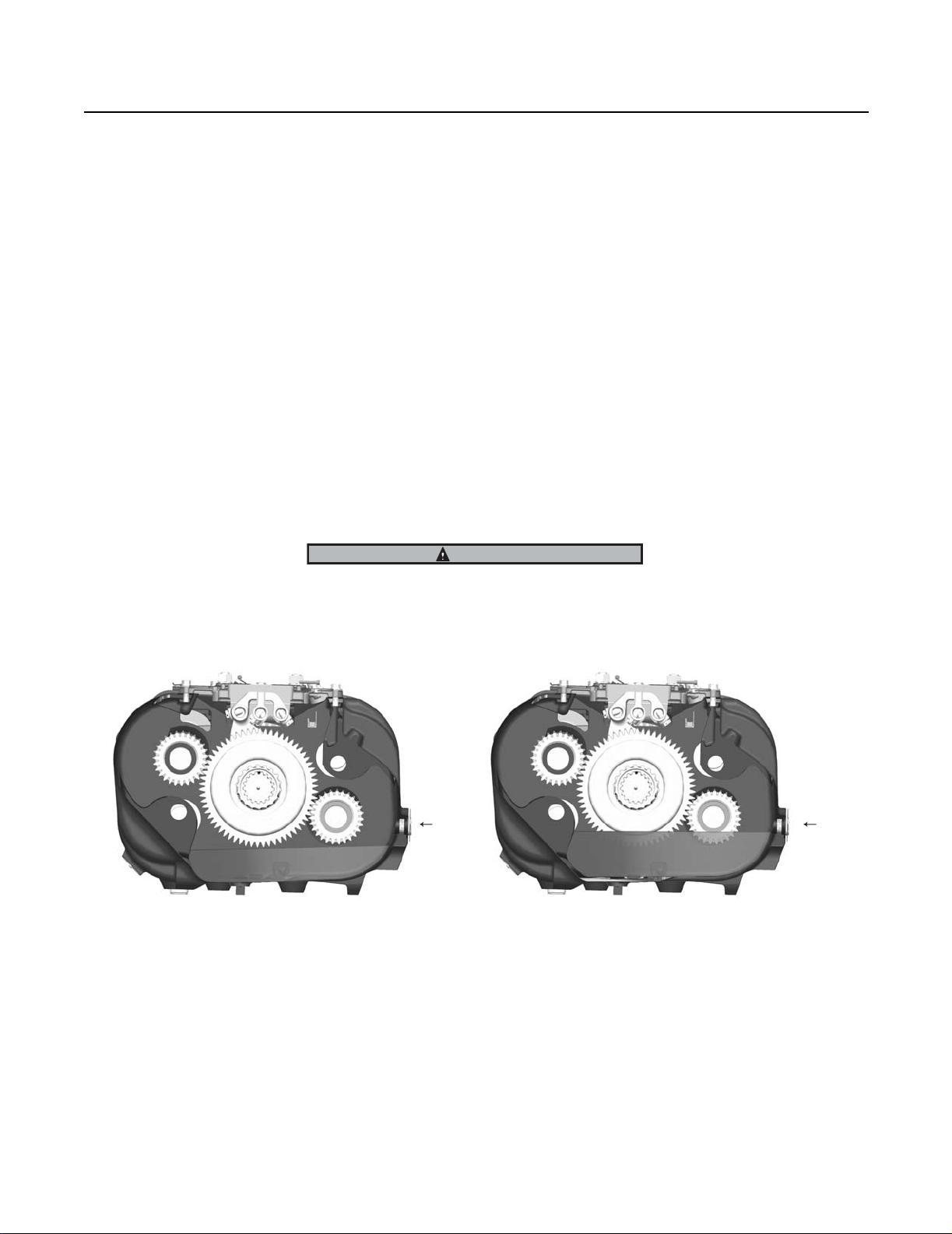
Power Flow by Gear
Note: The heavy lines in all figures represent the power flow path.
All the gearing in the transmission is constantly rotating because the transmission uses constant mesh gearing. However, only
the engaged gears have power (torque) transmitted across the gear set. Sliding clutches located on the front section and auxiliary section mainshafts slide forward or rearward to engage into a selected gear. Torque comes through the gear set only after
the sliding clutch engages the gear.
a. Power (torque) from the vehicle’s engine is transferred to the transmission’s input shaft.
b. The input shaft rotates the main drive gear through internal splines in the hub of the gear.
c. The main drive gear meshes with both countershaft drive gears splitting the engine torque equally across both gears.
d. Only those gears selected by the sliding clutches have torque across them even though all gears in the transmission
turn all the time.
e. The following illustrations show the torque path in all ten (10) gears and both reverse gears.
Transmission Power Flow
Low Reverse Gear
1. Sliding Clutch Rearward
2. Splitter Clutch Rearward
3. Synchronizer in Low Range
1
1st Gear
1. Sliding Clutch Forward
2. Splitter Clutch Rearward
3. Synchronizer in Low Range
231
2
1
3
High Reverse Gear
1. Sliding Clutch Rearward
2. Splitter Clutch Forward
3. Synchronizer in Low Range
3
2
2
1
3
2nd Gear
1. Sliding Clutch Forward
2. Splitter Clutch Forward
3. Synchronizer in Low Range
24
Page 31

Transmission Power Flow
21
3rd Gear
1. Sliding Clutch Rearward
2. Splitter Clutch Rearward
3. Synchronizer in Low Range
1
5th Gear
1. Sliding Clutch Forward
2. Splitter Clutch Rearward
3. Synchronizer in Low Range
3
1
3
2
4th Gear
1. Sliding Clutch Rearward
2. Splitter Clutch Forward
3. Synchronizer in Low Range
3
2
1
2
3
6th Gear
1. Sliding Clutch Forward
2. Splitter Clutch Forward
3. Synchronizer in Low Range
123
7th Gear
1. Sliding Clutch Rearward
2. Splitter Clutch Rearward
3. Synchronizer in High Range
25
1
8th Gear
1. Sliding Clutch Rearward
2. Splitter Clutch Forward
3. Synchronizer in High Range
3
2
Page 32

Transmission Power Flow
1
9th Gear
1. Sliding Clutch Forward
2. Splitter Clutch Rearward
3. Synchronizer in High Range
2
2
3
1
3
Transmission Power Flow
10th Gear
1. Sliding Clutch Forward
2. Splitter Clutch Forward
3. Synchronizer in High Range
26
Page 33

Timing
Gear Sets to be Timed
Auxiliary Mainshaft
Drive Gear Set
3rd/4th Gear Set
Splitter Gear Set
27
Page 34

Timing
Timing Procedures
Special Instructions
Both front and rear countershaft assemblies must be "timed". Correct timing assures the mainshaft gears will be properly centered
between the countershafts.
Timing is a simple service procedure completed by marking the appropriate teeth of a gear set prior to installation and placing
them in proper mesh during assembly. Since Lightning models are assembled as a single unit, there are three critical gear sets
that must be timed. In the order in which they are assembled, these gears include: the splitter gear set, the auxiliary mainshaft
drive gear set, and the 3rd/4th gear set.
Since Lightning transmission models contain all helical style gearing and the countershafts are single piece units, the process of
marking the gear teeth is unique compared to other models.
Special Tools
• Tool Markers Dye
Procedure -
Timing
1. Marking the auxiliary mainshaft splitter gear
2. Prior to installing the splitter gear on the end of the auxiliary
mainshaft, clearly mark any two teeth that are directly opposite of each other. Mark the teeth on the front side of the gear
identified by the internal clutching teeth.
3. There should be an equal number of unmarked gear teeth
between the marked teeth.
1. Marking the auxiliary countershaft gears
2. Locate the timing mark on the rear side of the forward most
gear (auxiliary coutershaft driven gear) and mark the two adjacent teeth next to the timing mark as shown.
3. Repeat the procedure for the two teeth on the next gear (auxiliary countershaft splitter gear) that line up exactly with the
timing mark on the drive gear.
28
Page 35

Timing
1. Marking the mainshaft gears
2. Prior to building the mainshaft assembly the auxiliary countershaft drive gear and the 3rd /4th mainshaft gear must be
marked for timing purposes. Clearly mark any two teeth that
are directly opposite of each other. Mark the teeth on the
front side of the gear so the teeth can be identified during
transmission assembly.
3. There should be an equal number of unmarked gear teeth
between the marked teeth.
1. Marking the front countershaft gears
2. Locate the timing mark on the flat section of the countershaft between the two smallest gears.
3. Mark the two adjacent teeth on the 3rd/4th gear that line up
with the timing mark.
1. Meshing the marked gearing during assembly
2. Install the splitter gear.
3. Install the auxiliary countershafts in the transmission case
with the timing marks lined up with the splitter gear marked
teeth.
29
Page 36

4. Install the mainshaft assembly with the marked teeth on the
auxiliary drive gear lined up between the marked teeth on the
auxiliary countershaft driven gears.
5. Install the countershafts with the two adjacent marked teeth
lined up on each side of the marked tooth on the mainshaft
gears.
6. Follow the assembly procedures in the "Bench Service" section.
Timing
Timing
30
Page 37

In-Vehicle Service Procedures
How to Remove the ECU
Special Instructions
None
Special Tools
• Typical Service Tools
Procedure -
1. Place the transmission in the reverse gear position.
2. Drain the vehicle air tanks.
3. Disconnect the vehicle wire harness connector from the ECU
using a 1/4" nut driver.
4. Remove the nine ECU capscrews.
5. Remove the ECU, spacer plate, sealing plate, and actuating
washer.
31
Page 38

How to Install the ECU
Special Instructions
None
Special Tools
• Typical Service Tools
Procedure -
1. Place the transmission in the reverse gear position.
2. Position the actuating washer onto the end of the shift shaft
and make sure it is rotated fully clockwise.
In-Vehicle Service Procedures
In-Vehicle Service Procedures
3. Assemble the ECU, spacer plate, and sealing plate.
4. Position the ECU assembly over the actuating washer so the
finger lines up with the range position sensor.
5. Make sure the ECU is fully seated against the case and install
the nine ECU capscrews.
6. Torque the ECU capscrews to 20-23 lb-ft (27-31 Nm).
7. Attach the vehicle interface harness to the ecu, tighten connector screw to 7–13 lb-in (.8–1.5 Nm).
32
Page 39

In-Vehicle Service Procedures
How to Remove the Air Filter/Regulator
Special Instructions
The air filter/regulator has two (2) O-rings located between the filter/regulator and the transmission case mounting surface.
Special Tools
• Typical Service Tools
Procedure -
1. Drain pressure from the vehicle air system.
2. Disconnect the air supply line from vehicle air system.
3. From the air filter/regulator, remove the two (2) capscrews.
4. From the main case, remove the air filter/regulator.
5. From the air filter/regulator, remove the two (2) O-rings.
6. Inspect the O-rings for cracks or distortion.
7. Remove the air supply fitting.
33
Page 40

In-Vehicle Service Procedures
How to Install the Air Filter/Regulator
Special Instructions
The air filter/regulator has two (2) O-rings located between the filter/regulator and the transmission case.
Special Tools
• Typical Service Tools
Procedure -
1. Insure the two o-rings are positioned in the recessed ports
located on the air filter/regulator mounting surface on the
transmission case.
2. Install the vehicle air supply line fitting with pipe thread sealant and position for correct air line routing.
In-Vehicle Service Procedures
3. Position the air filter/regulator assembly on the transmission case.
4. Apply Eaton/Fuller Sealant #71205 or equivalent to the two
(2) retaining capscrews.
5. Install the two (2) retaining capscrews, tighten to 9-10 lb-ft
(12-14 Nm) of torque.
6. Connect the air supply line from the vehicle air supply.
7. Charge the vehicle air system and inspect for air leaks.
34
Page 41

In-Vehicle Service Procedures
How to Remove the Shift Knob
Special Instructions
None
Special Tools
• Typical Service Tools
Procedure -
1. Pull down on the skirt portion of the shift knob to reveal the
electrical connector and the jam nut.
2. Disconnect the three-wire electrical connector.
3. Loosen the jam nut at the base of the knob.
4. Unscrew the knob from the shift lever.
5. If the skirt is to be removed from the lever, note the location
of the wire harness or harnesses in the skirt slots, and remove the jam-nut before removing the skirt section.
35
Page 42

How to Install the Shift Knob
Special Instructions
None
Special Tools
• Typical Service Tools
Procedure -
1. Slide the skirt over the shift lever and position the electrical
harness or harnesses into the appropriate slots, so the alignment pins on the skirt match the alignment holes in the knob
when installed.
In-Vehicle Service Procedures
In-Vehicle Service Procedures
2. Thread the jam nut and shift knob on the shift lever. Position
the shift knob so the splitter button faces the driver’s side of
the vehicle.
3. Tighten the jam nut against the bottom of the shift knob and
torque the nut to 35-45 lb-ft.
4. Attach the electrical connector from the lever harness to the
shift knob.
5. Slide the skirt up to the shift knob and position the electrical
connector in the skirt. Line up the pins from the skirt to the
holes on the shift knob and snap the skirt on the shift knob.
Note: The shift knob skirt is designed to snap correctly on
the knob only one way. If it is installed in the opposite
direction it will not line up correctly.
36
Page 43

In-Vehicle Service Procedures
How to Remove the Gear Shift Lever/Remote Shift Control
Special Instructions
Remote control housings are removed the same way as gear shift levers.
Special Tools
• Typical Service Tools
Procedure -
1
1. Remove the four retaining capscrews from the shift lever
base.
2
1. Housing
2. Capscrew
3. Gasket
3
2. To break the gasket seal, lightly strike the gear shift control
housing.
3. Remove the gear shift lever control housing to expose the
gasket.
4. Remove the gasket and clean the surface area the replacement gasket will contact.
37
Page 44

In-Vehicle Service Procedures
How to Install the Gear Shift Lever/Remote Shift Control
Special Instructions
Remote control housings are installed the same way as gear shift levers.
Special Tools
• Typical Service Tools
Procedure -
1. Position a new gasket on the shift lever/shift control housing
mounting surface.
In-Vehicle Service Procedures
2. Install the gear shift lever base/shift control housing. Make
sure the tip (finger) of the shift lever fits into the round hole
in the shift block.
3. Apply Eaton®Fuller® thread sealant #71205 or equivalent to
the retaining capscrews.
1. Housing
2. Capscrew
3. Gasket
4. Install the retaining capscrews and tighten to 40-45 lb-ft
(54-61 Nm) of torque.
Final Check
Make sure the capscrews are properly torqued.
Make sure you can shift the transmission.
1
2
3
38
Page 45

In-Vehicle Service Procedures
How to Adjust the Remote Shift Control (LRC Type)
Special Instructions
The following is a typical adjustment procedure for an LRC type slave control. It is recommended that the OEM Chassis Service
Manual be consulted first.
Procedure -
1
1. Move the gear shift lever forward or backward to the neutral
2
position.
D
3
4
B
A
6
5
7
2. Move the gear shift lever sideways, toward reverse, until you
feel resistance from the reverse plunger spring. DO NOT
shift to reverse. The shift finger must remain in this position
while you are making all the adjustments.
3. Remove the cotter pin, castle nut and ball joint A from the
selection lever. Do not remove the ball joint from the pivot
link.
4. Loosen the capscrew B and remove the shift arm from the
inner shift shaft. Do not disconnect the selection lever from
the shift arm.
1. Reach Rod
2. Turnbuckle
3. Selection Lever
4. Inner Shift Finger
5. Shift Arm
6. Pivot Link Assembly
7. Inner Shift Shaft
39
2
90
5. Turn the shift arm until it is at a right angle (90°) to the selection lever as viewed from the side.
Note: Ideally, the shift arm should be adjusted 90° to the se-
lection lever as described, but in some chassis configurations it may be necessary to index the shift arm in
1
the vertical position. Indexing the shift lever is done to
prevent shift lever jump out. This type of adjustment
will cause an unequal amount of gear shift lever travel
between neutral and a forward lever position as compared to neutral and a rearward lever position.
1. Selection Lever
2. Shift Arm
Page 46

6. Install the shift arm on the splines of the inner shift shaft.
You may have to move the shift arm 4° or 5° to align the
splines of the two parts. Disregard any movement of the
gear shift lever at this point. The gear shift lever will be adjusted later.
7. Tighten the capscrew B on the shift arm.
In-Vehicle Service Procedures
8. Connect the pivot link assembly ball joint to the selection lever. Secure it with the castle nut and cotter pin.
9. Loosen the jam nuts C on the pivot link.
1. Selection Lever
2. L.H. Thread
3. R.H. Thread
4. Shift Arm
5. Parallel
10. Check to be sure the inner shift finger is still in place.
11. Rotate the pivot link until the curved end of the selection lever is parallel with the shift arm as viewed from the rear .
12. Tighten the pivot link jam nuts C .
13. Loosen both capscrews on the turnbuckle D .
14. Check to be sure inner shift finger is still in place.
15. Rotate the turnbuckle to obtain the proper forward-backward neutral position of the gear shift lever in the cab.
1
2
C
3
C
In-Vehicle Service Procedures
4
5
1
2
D
3
4
16. Tighten one turnbuckle D capscrew .
17. Move the gear shift lever to the desired position.
18. Turn the second turnbuckle D capscrew.
19. Check for linkage obstructions in all gear positions.
B
A
6
5
7
40
Page 47

In-Vehicle Service Procedures
Neutral Switch Operation and Testing
Special Instructions
The neutral switch is a normally closed switch. An electrical current flows through it when the transmission shifter is in the neutral
position. When the transmission shifter is in gear, the switch is open and no current flows through it. Likewise, the switch is open
when the ball is depressed. The switch is actuated by the shift rail.
Special Tools
• Typical Service Tools
Procedure -
R
1
2
2
3
5
4
6
1
7
9
8
10
1. Disconnect the wiring from the switch.
2. Connect an ohm meter to check for continuity or a small
reading.
3. Place the transmission shift lever in the neutral position. The
ohm meter should register continuity or a small reading. If it
does, go to the next step. If it does not, remove the switch
and replace it.
4. Shift the transmission into all gear positions. The ohm meter
should read open or infinity. If it does not, remove the
switch. Then, depress the switch ball and check for continuity. The ohm meter should read open or infinity when the ball
is depressed.
1. Central Neutral Position (Neutral Switch Active)
2. Shift Position Diagram
5. Look into the neutral switch hole and verify the neutral
switch pin moves as the transmission is shifted from neutral
into gear.
If it does, replace the switch.
If not, remove and inspect the neutral switch pin for excessive wear. Replace, if necessary, or refer to bench service
procedures for disassembly of the shift shaft for inspection.
41
Page 48

How to Remove the Neutral Switch
Special Instructions
None
Special Tools
• Typical Service Tools
Procedure -
1. Remove the switch using a 7/8" deep well socket or box end
wrench.
In-Vehicle Service Procedures
In-Vehicle Service Procedures
42
Page 49

In-Vehicle Service Procedures
How to Install the Neutral Switch
Special Instructions
None
Special Tools
• Typical Service Tools
Procedure -
1. Install a new gasket.
2. Install the neutral switch. Tighten it to 15-20 lb-ft (20-27
Nm) of torque.
3. Connect the wiring to the switch.
43
Page 50

In-Vehicle Service Procedures
Reverse Switch Operation and Testing
Special Instructions
The reverse switch is a normally open ball switch. When the transmission is shifted into reverse, a ramp on the reverse yoke bar
contacts and raises a pin. The pin depresses the ball on the switch, which closes the switch contact, allowing current to flow
through the switch and light up the vehicle's backup lights.
Special Tools
• Typical Service Tools
Procedure -
1
1. Disconnect the wiring from the switch.
2. Connect an ohm meter to check for continuity.
3. Place the transmission shift lever in any position except reverse. If the switch is working properly, the ohm meter
should read open or infinity. If it is not, remove the switch
and recheck it for continuity. Replace as necessary.
R
3
4
7
8
In-Vehicle Service Procedures
1. Reverse Position (Rev Switch Active)
2. Shift Position Diagram
4. Place the transmission shift lever in the reverse position. If
the switch is working properly, the ohm meter should register continuity, or a small reading. If it does not, remove the
switch and recheck it for continuity. Replace as necessary.
Also, check for sticking or excessive wear of the reverse pin.
1
2
2
5
6
9
10
44
Page 51

In-Vehicle Service Procedures
How to Remove the Reverse Switch
Special Instructions
None
Special Tools
• Typical Service Tools.
Procedure -
1. Remove the switch using a 7/8" deep well socket or box end
wrench.
45
Page 52

How to Install the Reverse Switch
Special Instructions
None
Special Tools
• Typical Service Tools
Procedure -
1. Insert the reverse pin in the reverse switch bore (only if pin
is removed).
2. Install new gasket on switch.
3. Install the reverse switch. Tighten it to 15-20 lb-ft (20-27
Nm) of torque.
In-Vehicle Service Procedures
In-Vehicle Service Procedures
4. Connect the wiring to the switch.
46
Page 53

In-Vehicle Service Procedures
How to Remove the Shift Shaft Seal
Special Instructions
None
Special Tools
• Typical Serivce Tools
Procedure -
1. Place the transmission in the reverse gear position.
2. Drain the vehicle air tanks.
3. Disconnect the vehicle wire harness connector from the ECU
using a 1/4" nut driver.
4. Remove the nine ECU capscrews.
5. Remove the ECU, spacer plate, sealing plate, and actuating
washer.
6. Locate the two opposing holes on the metal sleeve of the
seal assembly and insert the tips of the seal pulling tool
(Tool ID T11, SPX P/N J44099). Then slide the seal out of
the shift shaft bore.
47
Page 54

How to Install the Shift Shaft Seal
Special Instructions
None
Special Tools
• Typical Service Tools
Procedure -
1. Lubricate the seal with transmission oil.
2. Slide the seal into the shift shaft bore until it is flush with the
edge of the hole.
In-Vehicle Service Procedures
In-Vehicle Service Procedures
3. Place the transmission in the reverse gear position.
4. Position the actuating washer onto the end of the shift shaft
and make sure it is rotated fully clockwise.
5. Assemble the ECU, spacer plate, and sealing plate.
6. Position the ECU assembly over the actuating washer so the
finger lines up with the range position sensor.
48
Page 55

In-Vehicle Service Procedures
7. Make sure the ECU is fully seated against the case and install
the nine ECU capscrews.
8. Torque the ECU capscrews to 20-23 Lb-ft (27-31 Nm).
9. Attach the vehicle interface harness to the ECU and tighten
connector screw to 7–13 lb-in (.8–1.5 Nm).
49
Page 56

In-Vehicle Service Procedures
How to Remove the Oil Seal - Magnetic Speedometer
Special Instructions
Prior to replacing the seal, carefully inspect the transmission to make sure the oil leakage is coming from the seal. Pay particular
attention to the speedometer parts, rear bearing cover gasket surfaces, rear countershaft bearing covers, and shift bar housing.
For additional information on rear seal service, refer to the Seal Maintenance Guide TCSM-0912.
Special Tools
• Brass drift
• Item T1: Output yoke puller
• Item T15: Slide hammer
See Tool Information
Procedure -
1. Disconnect the driveshaft and U-joint from the output yoke
according to the OEM or driveshaft manufacturer’s instructions.
In-Vehicle Service Procedures
2. Shift the transmission into 1st gear or low gear (Low Range)
to prevent the output yoke from turning when loosening the
output yoke nut.
3. Remove the output yoke nut using a 70 mm or 2 3/4" socket.
4. Use an output yoke puller to remove the output yoke (Tool
ref. ID T1).
5. Remove the speedometer sensors from the rear bearing
cover.
TIP: If the sensor is a thread in type, note the number of
threads exposed so the sensor can be reinstalled to the
same depth. If the sensor is a push in type, remove the hold
down capscrew and pull the sensor out of the bore.
6. Remove the speedometer rotor/seal sleeve and the O-ring.
50
Page 57

In-Vehicle Service Procedures
7. Pry the seal out using a large screwdriver or prybar in the
metal groove of the seal.
NOTE: The seal will be damaged during removal and must be
replaced.
8. Remove seal slinger from the speedometer rotor/seal sleeve
using a brass drift and hammer.
9. Inspect all parts of the oil seal for wear, scratches, burrs, or
other damage.
NOTE: Replace the seal surface if it is worn or damaged. Do
not attempt to salvage the seal mating surface with crocus
cloth, filing, etc.
51
Page 58

In-Vehicle Service Procedures
How to Install the Output Shaft Oil Seal - Magnetic Speedometer
Special Instructions
To prevent oil leaks, do not touch the seal lip, and make sure the seal driver is clean.
Special Tools
• Oil seal driver
• Oil seal slinger driver
See Tool Information, Eaton Aftermarket Tools for part numbers.
Procedure -
1. Place a seal on the oil seal driver, and drive the new seal into
the rear bearing cover. The seal is fully installed when the
flange on the seal is flush with the shoulder in the bore.
In-Vehicle Service Procedures
2. Install the new slinger on speedometer rotor/seal sleeve using a slinger driver.
3. If previously removed, install the O-ring over the output
shaft.
Note: To avoid creating oil leaks, make sure the speedome-
ter rotor/seal sleeve is free from contaminants.
4. Install the speedometer rotor/seal sleeve over the output
shaft, and install the speedometer sensors.
5. Install the output yoke over the output shaft. The yoke
should slide on and stop before contacting the speedometer
rotor. As the output shaft nut is installed, the output yoke will
contact the speedometer rotor.
6. Inspect the output shaft nut for damage and wear. If the nylon locking material is damaged or excessively worn, use a
new output nut.
Note: The nylon locking material must be in good condition
so the nut does not loosen when the vehicle is in use.
52
Page 59

In-Vehicle Service Procedures
7. Lightly oil the output shaft threads and the output nut
threads, and install the nut. Torque the nut to 450-500 Lb ft (610-677 Nm).
8. Connect the driveshaft and U-joint according to the OEM or
driveshaft manufacturer's instructions.
53
Page 60

How to Remove the Output Bearing Cover
Special Instructions
None
Special Tools
• Typical Service Tools
Procedure -
1. Disconnect the driveshaft and universal joint from the output
yoke according to OEM or driveshaft manufacturer's instructions.
2. Drain the transmission oil.
3. Shift the transmission into 1st gear or low gear to prevent
the output yoke from turning when you loosen the output
yoke nut.
In-Vehicle Service Procedures
In-Vehicle Service Procedures
4. Remove the output yoke nut using a 70 mm or 2 3/4" socket.
5. Remove the output yoke. Use an output yoke puller (Tool ref.
ID T1).
6. Remove the speedometer sensor from the rear bearing cover.
7. Remove the six bearing cover capscrews.
54
Page 61

In-Vehicle Service Procedures
8. Use a pry-bar to break the bearing cover loose from the case,
note the orientation of the speed sensor openings for later
re-assembly.
Note: If the sensor is a thread in type, note the number of
threads exposed so the sensor can be reinstalled to
the same depth. If the sensor is a push in type, remove the hold down capscrew and pull the sensor out
of the bore.
9. Remove the speedometer rotor/seal sleeve and the O-ring.
10. Pry the seal out using a large screwdriver or prybar in the
metal groove of the seal.
Note: The seal will be damaged during removal and must be
replaced.
11. Remove seal slinger from the speedometer rotor/seal sleeve
using a brass drift and hammer.
12. Inspect all parts of the oil seal for wear, scratches, burrs, or
other damage.
Note: Replace the seal surface if it is worn or damaged. Do
not attempt to salvage the seal mating surface with
crocus cloth, filing, etc.
55
Page 62

How to Install the Output Bearing Cover
Special Instructions
None
Special Tools
• Typical Service Tools
Procedure -
1. Thoroughly clean and inspect the sealing surfaces on the
transmission case and the output bearing cover for gouges
or distortion, replace if necessary.
2. Apply RTV sealant per application guidelines to the transmission case.
3. Place the bearing cover on the case in the same orientation
as the one removed.
In-Vehicle Service Procedures
In-Vehicle Service Procedures
4. Install the six bearing cover retaining capscrews.
5. Torque the capscrews to 47-52 lb-ft (63-70 Nm).
6. Make sure the output shaft O-ring seal is in place and install
the speedometer rotor/spacer and output yoke. The yoke
should slide on and stop before contacting the speedometer
rotor. As the output shaft nut is installed, the output yoke will
contact the speedometer rotor and output yoke nut. Tighten
the output yoke nut to 450-500 lb-ft (610-677 Nm).
56
Page 63

In-Vehicle Service Procedures
7. Install the output speed sensor and retaining capscrew.
Tighten capscrew to 20-23 lb-ft (27-31Nm).
8. Add required amount of oil per transmission oil fill specifications.
9. Connect vehicle driveshaft to output yoke per vehicle OEM
and driveshaft manufacturer’s instructions.
57
Page 64

How to Remove the Oil Cooler Fitting
Special Instructions
None
Special Tools
• Typical Service Tools
Procedure -
1. Locate the vehicle transmission cooler lines running to the
rear of the transmission.
If the vehicle is equipped with cooler line shut-off valves,
close the cooler shut-off valves and drain the cooler lines.
If the vehicle is not equipped with cooler line shut-off valves,
completely drain the engine cooling system and cooler lines
running to the transmission according to vehicle OEM
guidelines.
In-Vehicle Service Procedures
In-Vehicle Service Procedures
2. Remove the transmission drain plug and drain the transmission oil.
3. Disconnect the cooler lines at the rear of the transmission.
Remove the cooler hose adapter fittings that thread into the
transmission cooler interface fittings. Note the orientation of
the hose fittings for future reassembly.
58
Page 65

In-Vehicle Service Procedures
How to Install the Oil Cooler Fitting
Special Instructions
None
Special Tools
• Typical Service Tools
Procedure -
1. Install new O-rings on existing fittings or replace the complete fittings if damaged.
2. Generously coat the cooler fitting internal and external Orings with Eaton Fuller silicon lubricant #71206 or equivalent
before installing them into the transmission case.
3. Pilot the fitting over the ends of the cooler tube and slide into
the threaded fitting bore, until the threads on the fitting contact the threads in the bore. Because of the tight O-ring fit
both into the bore and over the end of the tube, you must
push the fitting into the borewhile turning to engage the
threads. Tighten fittings to 40-50 lb-ft (54-67 Nm).
4. Install the O-ring type cooler hose adapter fittings into the
transmission interface fittings. Then adjust the inlet and outlets in the direction they were removed, and tighten the locking nuts on the fittings.
5. Install the cooler hoses to the transmission and open the
cooler line shut-off valves, or refill the vehicle cooling system according to the vehicle OEM guidelines.
Replace the transmission drain plug and tighten to 35-50 lbft (47-67 Nm). Refill the transmission to the required lubrication fill level.
59
Page 66

In-Vehicle Service Procedures
How to Remove the Auxiliary Countershaft Bearing Cover
Special Instructions
None
Special Tools
• Typical Service Tools
Procedure -
1. Drain the transmission oil.
2. Remove the four bearing cover capscrews.
In-Vehicle Service Procedures
3. Use a pry bar between the case and bearing cover to break
the bearing cover seal.
60
Page 67

In-Vehicle Service Procedures
How to Install the Auxiliary Countershaft Bearing Cover
Special Instructions
None
Special Tools
• Typical Service Tools
Procedure -
1. Thoroughly clean and inspect the sealing surfaces on the
transmission case and the output bearing cover for gouges
or distortion, replace if necessary.
2. Apply RTV sealant per application guidelines to the transmission case.
3. Install the bearing cover on the case with the lube slot in the
cover lined up with the lube hole in the case.
4. Install the four bearing cover capscrews and torque to 47-52
lb-ft (63-70 Nm).
61
Page 68

In-Vehicle Service Procedures
How to Remove the Range Piston and Range Bar O-Ring
Special Instructions
None
Special Tools
• Typical Service Tools
In-Vehicle Service Procedures
8
7
9
6
10
5
11
4
2
1
3
1. Nut
2. Piston
3. Yoke Bar
4. Snap Ring
5. Washer
6. O- Ring
7. Pin
8. Range Yoke Assy
9. Retainer
10. Step Washer
11. Screw
62
Page 69

In-Vehicle Service Procedures
Procedure -
1. Place the transmission in the reverse gear position.
2. Drain the vehicle air tanks.
3. Disconnect the vehicle wire harness connector from the ECU
using a 1/4" nut driver.
4. Remove the nine ECU capscrews.
5. Remove the ECU, spacer plate, sealing plate, and actuating
washer.
6. Loosen the range piston retaining nut, but leave a few
threads still attaching.
7. Use a rubber tipped air gun to supply air pressure to the low
range air port located just to the right of the range cylinder.
This forces the piston out of the range bore and allows you
to remove the retaining nut and piston.
8. Remove the inner snap ring, then remove the washer and
range bar O-ring using a small magnet and O-ring pick tool
or small screwdriver.
63
Page 70

In-Vehicle Service Procedures
How to Install the Range Piston and Range Bar O-Ring
Special Instructions
None
Special Tools
• Typical Service Tools
In-Vehicle Service Procedures
8
7
9
6
10
5
11
4
2
1
3
1. Nut
2. Piston
3. Yoke Bar
4. Snap Ring
5. Washer
6. O- Ring
7. Pin
8. Range Yoke Assy
9. Retainer
10. Step Washer
11. Screw
64
Page 71

In-Vehicle Service Procedures
Procedure -
1. Apply a thin coating of silicon lube to the new range bar Oring and install the O-ring over the range bar. Make sure it
fully seats into the bore.
2. Install the washer and snap ring into the bore. Make sure the
snap ring fully expands and seats into the snap ring groove.
3. Apply a thin coating of silicon lube to the outside diameter of
the new range piston and install the piston on the end of the
range bar with the rubberized sealing surface toward the
range bar. Push the range bar and piston forward into the
bore.
4. Install the new range piston retaining nut and torque to 2535 lb-ft (34-47 Nm).
5. Place the transmission in reverse.
6. Position the actuating washer onto the end of the shift shaft
and make sure it is rotated fully clockwise.
7. Assemble the ECU, spacer plate, and sealing plate.
8. Position the ECU assembly over the actuating washer so the
finger lines up with the range position sensor.
9. Make sure the ECU is fully seated against the case and install
the nine ECU capscrews.
10. Torque the ECU capscrews to 20-23 lb-ft (27-31 Nm).
11. Attach the vehicle interface harness to the ECU, and tighten
the connector screw to 7–13 lb-in (.8–1.5 Nm).
65
Page 72

How to Remove the Splitter Piston
Special Instructions
None
Special Tools
• Typical Service Tools
10
In-Vehicle Service Procedures
In-Vehicle Service Procedures
7
8
1. Snap Ring
2. O- Ring
3. Piston
4. O- Ring
5. O- Ring
6. Piston
7. O- Ring
9
13
11
8. Yoke Bar
9. Pin
10. Splitter Yoke Assy
11. Screw
12. Step Washer
13. Retainer
12
6
5
4
3
2
1
66
Page 73

In-Vehicle Service Procedures
Procedure -
1. Place the transmission in the reverse gear position.
2. Drain the vehicle air tanks.
3. Disconnect the vehicle wire harness connector from the ECU
using a 1/4" nut driver.
4. Remove the nine ECU capscrews.
5. Remove the ECU, spacer plate, sealing plate, and actuating
washer.
6. Remove the splitter piston snap ring.
CAUTION: Very little air pressure is needed to remove piston, place a shop rag over the splitter piston to dampen the
force when the piston exits the splitter bore.
7. Use a rubber tipped air gun to supply air pressure to the constant air supply port located just to the left of the splitter cylinder bore. This will force the piston out of the splitter bore.
8. Remove the inner (neutral) piston from the splitter bar.
9. Use a small screwdriver or O-ring pick tool to remove the
two O-rings from the OD of the splitter bar, the O-ring from
the inner piston, and the O-ring from the outer splitter piston.
67
Page 74

How to Install the Splitter Piston
Special Instructions
None
Special Tools
• Typical Service Tools
10
In-Vehicle Service Procedures
In-Vehicle Service Procedures
7
8
1. Snap Ring
2. O- Ring
3. Piston
4. O- Ring
5. O- Ring
6. Piston
7. O- Ring
9
13
8. Yoke Bar
9. Pin
10. Splitter Yoke Assy
11. Screw
12. Step Washer
13. Retainer
11
12
6
5
4
3
2
1
68
Page 75

In-Vehicle Service Procedures
Procedure -
1. Apply a thin coating of Eaton Fuller silicon lubricant #71206
or equivalent to the new O-rings before installing them onto
the pistons and splitter bar.
2. Install the two smaller O-rings into the proper grooves on
the splitter bar.
3. Install the next larger O-ring on the proper groove of the inner splitter piston.
4. Install the inner piston into the splitter bore with the o-ring
end in first, so it fully seats over the splitter bar.
5. Install the largest O-ring onto the proper groove of the splitter piston.
6. Install the splitter piston into the splitter cylinder bore over
the end of the splitter bar, so the snap-ring groove is exposed.
7. Install the snap ring making sure it completely seats into the
snap-ring groove.
8. Place the transmission in the reverse gear position.
9. Position the actuating washer onto the end of the shift shaft
and make sure it is rotated fully clockwise.
10. Assemble the ECU, spacer plate, and sealing plate.
11. Position the ECU assembly over the actuating washer so the
finger lines up with the range position sensor.
12. Make sure the ECU is fully seated against the case and install
the nine ECU capscrews.
13. Torque the ECU capscrews to 20-23 lb-ft (27-31 Nm).
69
14. Attach the vehicle interface harness to the ECU and tighten
the connector screw to 7–13 lb-in (.8–1.5 Nm).
Page 76

How to Remove the Clutch Access Cover
Special Instructions
None
Special Tools
• Typical Service Tools
Procedure -
1. Squeeze the spring tabs together and remove from the slots.
2. Pull the cover down starting with the front first.
In-Vehicle Service Procedures
In-Vehicle Service Procedures
70
Page 77

In-Vehicle Service Procedures
How to Install the Clutch Access Cover
Special Instructions
None
Special Tools
• Typical Service Tools
Procedure -
1. Rotate the spring so the coil faces up and begin installing the
cover with the tabs to the rear.
2. Reinstall the spring tabs in the slots.
71
Page 78

Transmission Overhaul Procedures-Bench Service
How to Disassemble the Gear Shift Lever
Special Instructions
If total disassembly is needed, the Roadranger valve or Shift Knob, if present, must be removed first.
Release the spring one coil at a time.
Special Tools
• A vise with brass jaws or wood blocks
Procedures-Bench Service
Transmission Overhaul
3
10
11
2
4
12
1
5
6
7
13
8
14
9
1. Pin
2. Bushing
3. Upper Lever
4. Snap Ring
5. Rubber Boot
6. Spade Pin
7. Housing
8. Capscrew
9. Gasket
10. O-Ring
11. Washer
12. Lower Lever
13. Stepped Washer
14. Tension Spring
72
Page 79

Transmission Overhaul Procedures-Bench Service
Procedure -
1. On a non-isolated shift lever, remove the Roadranger valve
using the "How to Remove the Shift Knob" instructions in InVehicle Service Procedures. If the shift lever is equipped
with a lever isolator, remove the snap ring, bushing, and
cross pin to disconnect and remove the upper lever.
2. Slide the rubber boot up and off the shift lever shaft.
3. With the housing bottom facing up, secure the assembly in
a vise.
4. Use a large screwdriver to twist between the spring and
housing, forcing the spring from under the housing lugs.
5. From inside the housing tower, remove the tension spring,
washer, and gear shift lever.
6. In models so equipped, remove the nut and washer from the
housing bore.
7. Remove and inspect the spade pin from the housing tower
spade pin bore. Replace if damaged.
8. Inspect the O-ring in the housing tower inside groove. Replace if damaged.
73
Page 80

Transmission Overhaul Procedures-Bench Service
How to Assemble the Gear Shift Lever
Special Instructions
Inspect tension spring and washer for wear.
Apply Eaton rust preventative lubricant #71212 or equivalent to the shift lever pivot ball. A rust preventative lubricant film should
cover all surfaces between and including the pivot ball.
Seat the tension spring one coil at a time.
Special Tools
• A vise with brass jaws or wood blocks
• Tension Spring Driver (see recommended tool list)
2
1
Procedures-Bench Service
Transmission Overhaul
3
10
11
4
12
5
6
7
13
8
14
1. Pin
2. Bushing
3. Upper Lever
4. Snap Ring
5. Rubber Boot
6. Spade Pin
7. Housing
9
8. Capscrew
9. Gasket
10. O-Ring
11. Washer
12. Lower Lever
13. Stepped Washer
14. Tension Spring
74
Page 81

Transmission Overhaul Procedures-Bench Service
Procedure -
1. With housing bottom facing up, secure the assembly in a
vise.
2. If the spade pin is damaged, install a new spade pin in thehousing tower bore.
3. In models so equipped, install the nut and washer in the
housing bore.
4. If the O-ring is damaged replace it. Lubricate the new O-ring
with Eaton/Fuller lubricant #71206 or equivalent. Install the
O-ring in the housing tower inside groove.
5. Align the lever ball slot with the spade pin and position the
gear shift lever in the housing tower.
6. With dished-side up, install the washer over the ball.
7. Use a tension spring driver to install the tension spring under the housing lugs.
8. Remove the assembly from the vise.
9. Install a rubber boot over the gear shift lever and against the
housing.
Final Check
Make sure the gear shift lever moves freely.
75
Page 82

Transmission Overhaul Procedures-Bench Service
How to Remove Output Yoke
Special Instructions
None
Special Tools
• Output Yoke Puller (Tool ref. ID T1)
Procedure -
1. Remove the speedometer sensor retaining capscrew and the
speedometer sensor from the rear bearing cover.
Procedures-Bench Service
Transmission Overhaul
2. Remove the output nut using a 70 mm or 2 3/4" socket.
TIP:To prevent the output shaft and yoke from rotating while
removing the nut, use a fixture to hold the yoke.
3. Remove the output yoke. Use the output yoke puller (Tool
ref. ID T1).
4. Remove the speedometer rotor and O-ring from the output
shaft.
76
Page 83

Transmission Overhaul Procedures-Bench Service
How to Remove the ECU
Special Instructions
None
Special Tools
• Typical Service Tools
Procedure -
1. Place the transmission in the reverse gear position.
2. Disconnect the vehicle wire harness connector from the ECU
using a 1/4" nut driver.
3. Remove the nine ECU capscrews.
4. Remove the ECU, spacer plate, sealing plate, and actuating
washer.
77
Page 84

Transmission Overhaul Procedures-Bench Service
How to Remove the Auxiliary Countershaft Bearing Cover
Special Instructions
None
Special Tools
• Typical Service Tools
Procedure -
1. Drain the transmission oil.
Procedures-Bench Service
Transmission Overhaul
2. Remove the four bearing cover capscrews.
3. Use a pry bar between the case and bearing cover to break
the bearing cover seal.
78
Page 85

Transmission Overhaul Procedures-Bench Service
How to Orient Transmission for Overhaul
Special Instructions
None
Special Tools
• Lifting Chain
• Over Head Crane
Procedure -
1. Before beginning the overhaul procedure the transmission
must be mounted to a fixture that will allow for disassembly
and re-assembly in the vertical position.
2. Lift the transmission using a chain, a lifting device, and two
lifting eyelets attached to front cover capscrews inside the
clutch housing/front cover. The chain and lifting device must
have a minimum capacity of 1000 lbs.
79
3. Mount the transmission to the stand attached to a standard
1000 lb. minimum capacity automotive engine repair stand.
A stand that allows for rotation of the transmission is helpful
during tear down and assembly. (Tool ref. ID T2)
4. Do not disturb the RTV fasteners when mounting the transmission to the stand - use the extended PTO mounting studs
and the drain plug threaded opening for mounting.
Page 86

Transmission Overhaul Procedures-Bench Service
How to Remove and Disassemble Input Shaft and Oil Pump
Special Instructions
None
Special Tools
• Typical Service Tools
• Bearing Race Puller (Tool ref. ID T5)
2
1
Procedures-Bench Service
Transmission Overhaul
9
5
3
4
6
7
8
17
16
15
10
12
13
14
1. Capscrew & Washer
2. Front Brg Cover Assy
3. O- Ring
4. Oil Seal
5. Shim Kit
6. Bearing Cup
7. Bearing Cone
8. Screw
9. Eccentric Pump Assy
11
10. Input Shaft
11. Piston Pump
12. Snap Ring
13. Washer
14. Main Drive Gear
15. Bearing
16. Spherical Washer
17. Snap Ring
80
Page 87

Transmission Overhaul Procedures-Bench Service
Procedure -
1. Remove the six (6) capscrews from the input shaft bearing
cover.
2. Remove the input shaft assembly from the clutch housing/
front cover.
When removing the input shaft and bearing cover, striking the
input shaft with a maul can cause damage to the input shaft
and/or break the oil pump set screw.
3. Remove the set-screw that holds the eccentric pump in
place (5/64" allen wrench).
4. Remove the bearing cover and shim-pack from the input
shaft.
WARNING
5. Remove and discard the rubber O-ring from the bearing cover. Remove and set aside the shim-pack for future assembly.
Note: The shim pack will likely contain several shims of
varying thickness, it is helpful to keep the shim pack
together to provide a starting point when shimming
the mainshaft endplay during assembly.
6. Install the bearing race puller (Tool ref. ID T5) as shown and
remove the input bearing race from the input shaft bearing
cover.
7. Remove the input shaft seal as shown and discard.
81
Page 88

Transmission Overhaul Procedures-Bench Service
8. Press the input shaft bearing off the input shaft with an arbor
press using two flat 1/4’ plates inserted between the gear
and bearing cone hub or use bearing puller plate as shown.
9. ( See Bearing Plate Puller Design)
10. Remove the eccentric pump.
1.5" 1.5"
5.5"
3"
3"
6"
.375"
7"
Procedures-Bench Service
Transmission Overhaul
11. Remove the input snap ring from the main drive gear using
a small flat blade screwdriver.
12. Remove the snap ring and splined washer from the input
shaft.
13. Separate the input shaft and main drive gear then remove
the pump piston from the input shaft.
14. Remove the snap ring, beveled washer, and thrust bearing
from the end of the input shaft.
Note: The input shaft is hollow to provide lubrication into the
mainshaft, be sure to inspect and flush any debris
from the internal passage when servicing the input
shaft.
82
Page 89

Transmission Overhaul Procedures-Bench Service
How to Remove and Disassemble Clutch Housing/Front Cover
Special Instructions
None
Special Tools
• Typical Service Tools
Procedure -
1. Remove the sixteen (16) capscrews holding the front cover
to the main case (Eight (8) inside the clutch housing, six (6)
outside the housing threading into the main case, and two
(2) threading into the clutch housing from the main case).
2. Inspect capscrews.
Note: One (1) of the capscrews threading into the main case
on the right side of the housing is longer than the other. This capscrew must be reassembled in the same
location.
3. To break the seal between the clutch housing/front cover
and the transmission main case start with the output bearing
cover installed. Remove the O-ring and shim pack from the
input shaft and front bearing cover assembly and reinstall
into the front cover. Install three (3) opposing capscrews
and tighten until the front cover pops loose from the main
case. With the shim pack removed, the negative mainshaft
clearance will force the front cover seal to be broken.
4. Remove the housing.
5. Remove the two (2) capscrews holding the oil trough and remove the oil trough from front cover.
6. Remove front countershaft bearings from front cover using
a bearing puller (Tool ref. ID T4).
83
Page 90

Transmission Overhaul Procedures-Bench Service
7. Remove the capscrew holding the oil dam plate.
8. Remove oil dam plate from front cover.
Procedures-Bench Service
Transmission Overhaul
84
Page 91

Transmission Overhaul Procedures-Bench Service
How to Remove Output Bearing Cover
Special Instructions
None
Special Tools
• Typical Service Tools
Procedure -
1. Mark the output bearing cover in such a way to allow the
bearing cover to be reinstalled in the same location. The cover can be installed in two opposite positions.
2. Remove the six bearing cover capscrews. Use a pry-bar to
break the bearing cover loose from the case.
85
Page 92

Transmission Overhaul Procedures-Bench Service
How to Remove and Disassemble Front Countershaft
Special Instructions
None
Special Tools
• Bearing Race Puller (Tool ref. ID T6)
• Bearing Race Puller (Tool ref. ID T7)
1
1. Bearing — Outer Roller
2. Bearing — Inner Race
3. Welded Countershaft Assy
Procedure -
Procedures-Bench Service
Transmission Overhaul
3
2
1. Remove the left and right front countershafts by lifting them
directly out of the case from the front.
Note: Identify countershafts as they are removed by mark-
ing them ’left’ & ’right’ for future re-assembly.
86
Page 93

Transmission Overhaul Procedures-Bench Service
2. Use the bearing race puller (Tool ref. ID T6) to remove the
countershaft front bearing races.
3. Use the bearing race puller (Tool ref. ID T7) to remove the
auxiliary countershaft front bearing races from the front
countershafts.
87
Page 94

Transmission Overhaul Procedures-Bench Service
How to Remove and Disassemble Mainshaft
Special Instructions
None
Special Tools
• Typical Service Tools
1
2
Procedures-Bench Service
Transmission Overhaul
6
5
7
7
1. Sliding Clutch
2. Mainshaft Key
3. Roll Pin
4. Key
5. 4th Gear-Mainshaft
6. 1st Gear-Mainshaft
3
4
7
7. Washer
8. Sliding Clutch
9. Auxiliary Drive Gear
10. Reverse Gear-Mainshaft
11. Snap Ring
8
11
7
7
7
9
10
88
Page 95

Transmission Overhaul Procedures-Bench Service
Procedure -
1. Lift the mainshaft and shift shaft assembly out of the maincase as one unit.
2. Separate the shiftshaft assembly from the mainshaft assembly.
3. Remove the sliding clutch from the front of the mainshaft.
4. Remove snap ring.
5. Remove the snap ring and washer from the rear of the mainshaft.
6. Remove the auxiliary drive gear from the rear of the mainshaft as shown.
89
Page 96

Transmission Overhaul Procedures-Bench Service
7. Tap the mainshaft key out of the groove as shown with a
small punch.
8. Remove the key from the rear of the shaft.
Note: The three-sided mainshaft key is rounded on one cor-
ner to fit into the mainshaft groove. Installing the key
with one of the squared off corners into the mainshaft
groove makes disassembly and assembly very difficult.
9. Remove the reverse gear and washer.
10. Remove washer and sliding clutch.
Procedures-Bench Service
Transmission Overhaul
11. Remove 1st /2nd gear and washer.
12. Remove 3th/4th gear and washer.
13. Remove washer.
90
Page 97

Transmission Overhaul Procedures-Bench Service
How to Remove and Disassemble the Shift Shaft
Special Instructions
None
Special Tools
• Typical Service Tools
11
10
9
1
1. Shift Shaft Assy
2. Key
3. Shift Yoke
4. Shift Yoke
5. Plug
6. Spring
7
6
5
7. Spring
8. Plunger
9. Plug
10. Compression Spring
11. Plunger
2
3
8
4
91
Page 98

Transmission Overhaul Procedures-Bench Service
Procedure -
1. Separate the shiftshaft assembly from the mainshaft assembly.
2. Mount the shiftshaft assembly horizontally in a vise with
brass jaw protectors by clamping the small end in the vise.
3. Remove the neutral detent plug and spring.
4. Rotate the 1st & reverse shift fork clockwise into the reverse
detent position to align the shiftshaft key with the slot in the
fork.
Procedures-Bench Service
Transmission Overhaul
5. Line up the shiftshaft key with the slot in the 3rd & direct
shift fork.
6. Remove the shiftshaft key.
92
Page 99

Transmission Overhaul Procedures-Bench Service
7. Remove the neutral detent plunger.
8. Line up the 3rd & direct shift fork slot with the shiftshaft pin
and remove the fork.
9. Remove the reverse bias plug, spring, and plunger from the
1st & reverse shift fork.
10. Line up the 1st & reverse shift fork slot with the shiftshaft pin
and remove the fork.
93
Page 100

Transmission Overhaul Procedures-Bench Service
How to Remove and Disassemble Reverse Idler
Special Instructions
None
Special Tools
• Slide Hammer
Procedures-Bench Service
Transmission Overhaul
2
1
4
5
6
1. Reverse Idler Shaft
2. Reverse Idler Gear
3. Bearings
Procedure -
1. Remove the idler shaft retainer capscew.
4. Washer
5. Snap Ring
6. Capscrew
3
94
 Loading...