

Page 1

Troubleshooting Guide
Eaton Gen III Automated
Transmissions
TRTS0930 EN-US
August 2013
UltraShift®
AutoShift®
UltraShift® PLUS Linehaul Active Shifting (LAS)
UltraShift® PLUS Linehaul Small Step Efficiency (LSE)
UltraShift® PLUS Multipurpose Extreme Performance (MXP)
UltraShift® PLUS Multipurpose High Performance (MHP)
UltraShift® PLUS Vocational Active Shifting (VAS)
UltraShift® PLUS Vocational Construction Series (VCS)
UltraShift® PLUS Vocational High Performance (VHP)
UltraShift® PLUS Vocational Multipurpose Series (VMS)
UltraShift® PLUS Vocational Extreme Performance (VXP)
UltraShift® PLUS Passenger Vehicle (PV)
Page 2

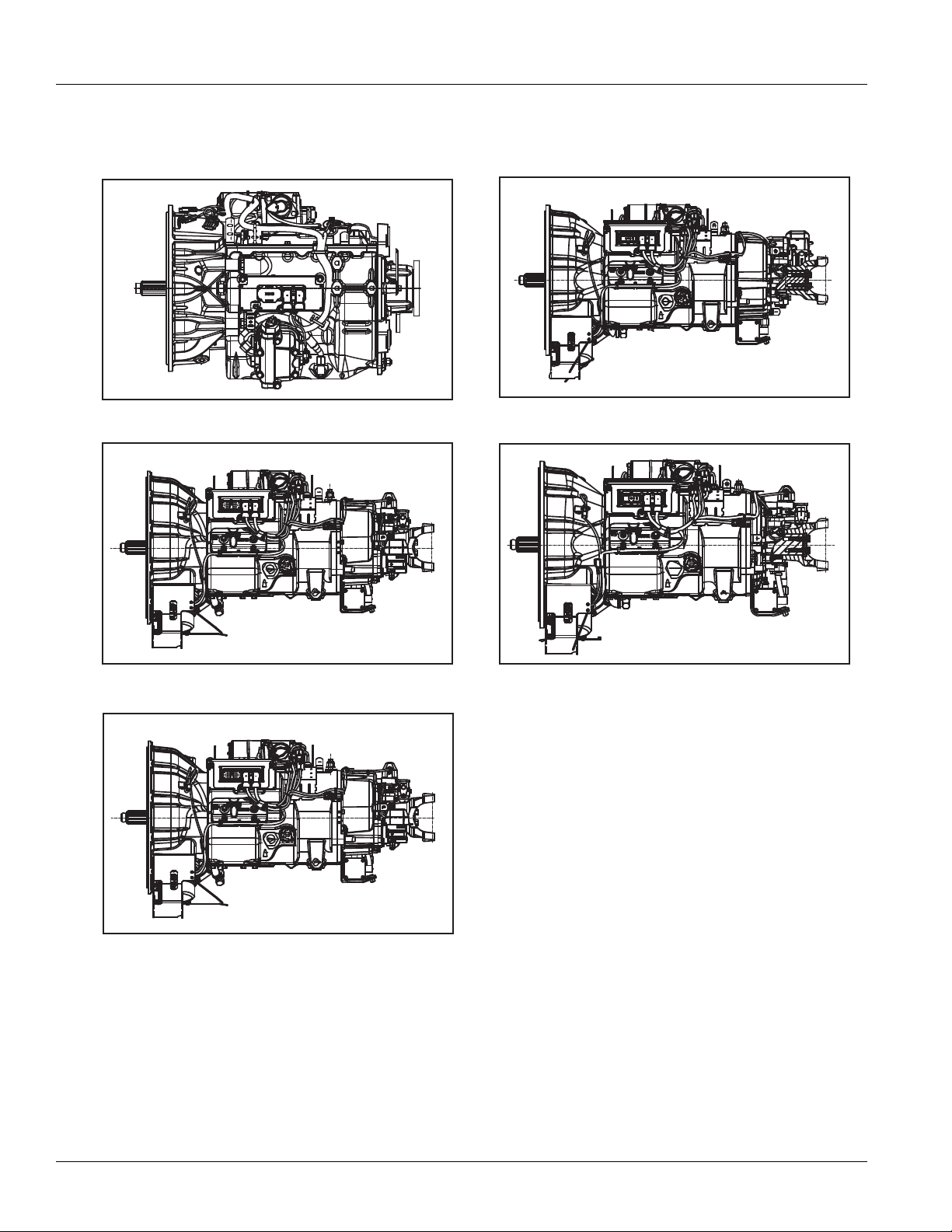
Model:
F-5405B-DM3
F-6405B-DM3
F-14E316B-LSE
F-15E316B-LSE
F-17E316B-LSE
FM-15E316B-LSE
FM-14D310B-LST
FM-15D310B-LST
FO-16D313E-LEP
FO-5406B-DM3
FO-6406A-AW3
FO-6406B-AW3
FO-8406A-AW3
FOM-16D313E-LEP
RTLO-14918A-AS3
RTLO-16913L-DM3
RTLO-16918A-AS3
RTO-10910B-DM3
RTO-12910B-AS3
RTO-12910B-DM3
RTO-14910B-AS3
RTO-14910B-DM3
RTO-14910C-AS3
RTO-16910B-AS3
RTO-16910B-DM3
RTO-16910C-AS3
RTO-18910B-AS3
FO-10E310C-VAS
FO-12E310C-VAS
FO-14E310C-VAS
FO-16E310C-VAS
FOM-14E310C-VAS
F-5505B-DM3
F-6505B-DM3
RTLO-18918A-AS3
RTLO-20918A-AS3
RTLO-22918A-AS3
RTLOM-16913L-DM3
RTO-10910B-AS3
RTOM-16910B-DM3
FO-14E310C-LAS
FO-16E310C-LAS
FO-18E310C-LAS
FOM-14E310C-LAS
FOM-15E310C-LAS
FOM-16E310C-LAS
FM-14E310B-LAS
FM-15E310B-LAS
EO-11E406B-PV
FOM-15E310C-VAS
FOM-16E310C-VAS
FO-10E308LL-VCS
FO-11E308LL-VCS
FO-12E308LL-VCS
FO-14E308LL-VCS
FO-16E308LL-VCS
FO-17E308LL-VCS
FO-16E313A-VHP
FO-18E313A-VHP
FO-20E313A-VHP
FO -10E309A LL-VMS
FO -11E309ALL-VMS
FO -12E309ALL-V MS
FO -14E30 9ALL-VMS
FO -16E309ALL-VM S
FO -17E309ALL-V MS
FO-14E313B-MHP
FO-16E313B-MHP
FO-18E313B-MHP
FO-20E313B-MHP
FO-14E318B-MXP
FO-16E318B-MXP
FO-18E318B-MXP
FO-20E318B-MXP
FO-22E318B-MXP
FO-14E318B-VXP
FO-16E318B-VXP
FO-18E318B-VXP
FO-20E318B-VXP
FO-22E318B-VXP
EO-11E406B-PVER
EO-11E406B-PVHR
EO-11E406B-PV
Page 3

TRTS0930
Table of Contents
T
able of Contents
General Information
Warnings and Cautions . . . . . . . . . . . . . . . . . . . . . . . . .1
Suggested Tools . . . . . . . . . . . . . . . . . . . . . . . . . . . . . .2
Transmission Models Included . . . . . . . . . . . . . . . . . . .3
Diagnostic Procedures. . . . . . . . . . . . . . . . . . . . . . . . . .6
Fault Code Retrieval/Clearing
Retrieving Fault Codes Manually . . . . . . . . . . . . . 10
Clearing Fault Codes Manually . . . . . . . . . . . . . . . 11
Retrieving Fault Codes with ServiceRanger . . . . . 11
Clearing Fault Codes with ServiceRanger. . . . . . . 12
Fault Code Isolation Procedure Index . . . . . . . . . . . . .13
Symptom-Driven Diagnostics Index . . . . . . . . . . . . . .15
Product Diagnostic (PD) Mode . . . . . . . . . . . . . . . . . .16
Electrical Pretest Procedures
Electrical Pretest . . . . . . . . . . . . . . . . . . . . . . . . . . . . .18
TECU Power Harness. . . . . . . . . . . . . . . . . . . . . . 19
Heavy-Duty Electric Clutch Actuator (ECA)
Power Harness. . . . . . . . . . . . . . . . . . . . . . . . . . . 20
Preferred +12 Volt Connections . . . . . . . . . . . . . . 22
Preferred +24 Volt Connections . . . . . . . . . . . . . . 24
TECU Ignition Circuit . . . . . . . . . . . . . . . . . . . . . . 26
J1939 Data Link. . . . . . . . . . . . . . . . . . . . . . . . . . 27
Electrical Pretest . . . . . . . . . . . . . . . . . . . . . . . . . . . . .28
Power-Up Sequence Test. . . . . . . . . . . . . . . . . . . . . . .32
Fault Isolation Procedures
Fault Code 11 - No TECU Operation. . . . . . . . . . . . . . .40
Fault Code 12 - Improper ECU Configuration. . . . . . . .44
Fault Code 13 - J1939 Shift Control Device . . . . . . . . .48
Fault Code 14 - Invalid Shift Lever Voltage
(without Park Pawl) . . . . . . . . . . . . . . . . . . . . . . . . . . .52
Fault Code 14 - Invalid Shift Lever Voltage
(with Park Pawl) . . . . . . . . . . . . . . . . . . . . . . . . . . . . .58
Fault Code 15 - HIL Shift Device Configuration . . . . . . 64
Fault Code 16 - High Integrity Link (HIL) . . . . . . . . . . .68
Fault Code 17 - Start Enable Relay
Fault Code 18 - ECA Communication Fault. . . . . . . . . .84
Fault Code 19 - CAN ECA Message Fault . . . . . . . . . . .88
Fault Code 21 - Auto Neutral Park Brake Switch . . . . . 92
Fault Code 22 - ABS CAN Message Fault . . . . . . . . . . . 98
Fault Code 26 - Clutch Slip . . . . . . . . . . . . . . . . . . . .102
Fault Code 27 - Clutch Disengagement . . . . . . . . . . .106
(SER) Circuit . . . . .80
Fault Code 28 - Clutch System. . . . . . . . . . . . . . . . . .112
Fault Code 29 - Remote Throttle Enable. . . . . . . . . . .118
Fault Code 31 - Momentary Engine Ignition
Interrupt Relay (MEIIR) Test . . . . . . . . . . . . . . . . . . .122
Fault Code 32 - Loss of Switch Ignition Power Test .128
Fault Code 33 - Low Battery Voltage Supply . . . . . . . 132
Fault Code 34 - Weak Battery Voltage Supply
Fault Code 35 - J1939 Communication Link . . . . . . . 144
Fault Code 36 - J1939 Engine Message. . . . . . . . . . . 150
Fault Code 37 - Power Supply . . . . . . . . . . . . . . . . . .156
Fault Code 41 - Range Failed to Engage. . . . . . . . . . . 162
Fault Code 42 - Splitter Failed to Engage . . . . . . . . . .168
Fault Code 43 - Range Solenoid Valve . . . . . . . . . . . . 174
Fault Code 44 - Inertia Brake Solenoid Coil . . . . . . . . 180
Fault Code 45 - High Capacity (HCIB)
or Low Capacity (LCIB) Inertia Brake Failure . . . . . . .186
Fault Code 46 - Splitter Direct and
Solenoid Valve . . . . . . . . . . . . . . . . . . . . . . . . . . . . . .190
Fault Code 51 - Rail Position Sensor . . . . . . . . . . . . .196
Fault Code 52 - Gear Position Sensor . . . . . . . . . . . .202
Fault Code 56 - Input Shaft Speed Sensor . . . . . . . . . 208
Fault Code 57 - Main Shaft Speed Sensor . . . . . . . . .214
Fault Code 58 - Output Shaft Speed Sensor. . . . . . . . 218
Fault Code 61 - Rail Select Motor . . . . . . . . . . . . . . .224
Fault Code 63 - Gear Select Motor. . . . . . . . . . . . . . .230
Fault Code 64 - ECA Fault . . . . . . . . . . . . . . . . . . . . .236
Fault Code 65 - ECA Speed Sensor Fault . . . . . . . . . . 240
Fault Code 66 - ECA Battery Voltage Fault . . . . . . . . .248
Fault Code 67 - ECA Ignition Voltage Fault. . . . . . . . . 254
Fault Code 68 - Grade Sensor . . . . . . . . . . . . . . . . . . 260
Fault Code 71 - Unable to Disengage Gear. . . . . . . . .264
Fault Code 72 - Failed to Select Rail. . . . . . . . . . . . . .270
Fault Code 73 - Failed to Engage Gear . . . . . . . . . . . .276
Fault Code 74 - Engine Speed Response Fault. . . . . .282
Fault Code 75 - Power Down In Gear. . . . . . . . . . . . . 286
Fault Code 81 - Gear Engagement Detected. . . . . . . . 290
Fault Code 83 - Shift Lever Missing. . . . . . . . . . . . . .294
Fault Code 84 - Shift Control
Fault Code 85 - Shift Control Device Incompatible. . . 302
Fault Code 99 - Direction Mismatch. . . . . . . . . . . . . .306
Indirect
Device Not Configured . 298
. . . . . . 138
2013.08.7
© 2013 Eaton Corporation. All rights reserved
i
Page 4

Table of Contents TRTS0930
Symptom Isolation Procedures
Up/Down Button Test. . . . . . . . . . . . . . . . . . . . . . . . .310
Start Enable Relay Contact Test . . . . . . . . . . . . . . . . .314
J1587 Data Link Test . . . . . . . . . . . . . . . . . . . . . . . . .320
Front Box Control Test . . . . . . . . . . . . . . . . . . . . . . . .326
AutoShift Will Not Engage a Gear
from Neutral Test . . . . . . . . . . . . . . . . . . . . . . . . . . . .332
Heavy-Duty UltraShift PLUS Will Not Eng
a Gear from Neutral Test . . . . . . . . . . . . . . . . . . . . . .340
UltraShift DM3 Will Not Engage a Gear
from Neutral Test . . . . . . . . . . . . . . . . . . . . . . . . . . . .348
UltraShift AW3 Clutch Engagement Test
AutoShift AS3 Shift Complaint Test . . . . . . . . . . . . . .358
Heavy-Duty UltraShift PLUS Shift Co
UltraShift DM3 Shift Complaint Test . . . . . . . . . . . . .378
UltraShift AW3 Shift Complaint Test . . . . . . . . . . . . .388
Shift Lever Back Light Test . . . . . . . . . . . . . . . . . . . .396
age
. . . . . . . . . .354
mplaint Test . . .368
Appendix
Connector Pin Descriptions
Non-ECA Products Transmission Controller
38-Way (Vehicle Interface Connector) . . . . . . . . 402
Push Button Shift Control 30-Way Connector . . 403
Cobra Lever 8-Way Connector . . . . . . . . . . . . . . 403
Non-ECA Products Transmission Controller
38-Way (Eaton Supplied Assembly). . . . . . . . . . 404
Heavy-Duty & Medium-Duty UltraShift PLUS
Transmission Controller
38-Way (Vehicle Interface Connector) . . . . . . . . 405
Heavy-Duty UltraShift PLUS T
Controller 38-Way (Eaton Supplied Assembly
Medium-Duty UltraShift PLUS T
Controller 38-Way (Eaton Supplied Assembly
Wiring Diagrams
UltraShift DM3 6-Speed Wiring Diagram
with Analog Shifter. . . . . . . . . . . . . . . . . . . . . . . 408
UltraShift DM3 6-Speed Wiring Diagram
with Push Button Shifter . . . . . . . . . . . . . . . . . . 410
UltraShift AW3 6-Speed Wiring Diagram
with Analog Shifter. . . . . . . . . . . . . . . . . . . . . . . 412
UltraShift AW3 6-Speed Wiring Diagram
with Push Button Shifter . . . . . . . . . . . . . . . . . . 414
Medium-Duty UltraShift PLUS Mo
Diagram with Analog Shifter . . . . . . . . . . . . . . . 416
Medium-Duty UltraShift PLUS Mo
Diagram with Push Button Shifter . . . . . . . . . . . 418
AutoShift 10-Speed Wiring Diagram
with Analog Shifter. . . . . . . . . . . . . . . . . . . . . . . 420
ransmission
) . 406
ransmission
) . 407
dels Wiring
dels Wiring
AutoShift 10-Speed Wiring Diagram
with Push Button Shifter . . . . . . . . . . . . . . . . . . 422
UltraShift 10-Speed Wiring Diagram
with Analog Shifter. . . . . . . . . . . . . . . . . . . . . . . 424
UltraShift 10-Speed Wiring Diagram
with Push Button Shifter . . . . . . . . . . . . . . . . . . 426
UltraShift 13-Speed Wiring Diagram
with Analog Shifter. . . . . . . . . . . . . . . . . . . . . . . 428
UltraShift 13-Speed Wiring Diagram
with Push Button Shifter . . . . . . . . . . . . . . . . . . 430
AutoShift 18-Speed Wiring Diagram
with Analog Shifter. . . . . . . . . . . . . . . . . . . . . . . 432
AutoShift 18-Speed Wiring Diagram
with Push Button Shifter . . . . . . . . . . . . . . . . . . 434
Heavy-Duty UltraShift PLUS Mo
Wiring Diagram with Analog Shifter. . . . . . . . . . 436
Heavy-Duty UltraShift PLUS Mo
Wiring Diagram with Push Button Shifter . . . . . 438
Eaton Cobra Lever Wiring Diagram . . . . . . . . . . 440
OEM Shift Lever Wiring Diagram . . . . . . . . . . . . 441
Eaton Push Button Wiring Diagram . . . . . . . . . . 442
OEM J1939 Shift Input Device Wiring Diagram . 444
Heavy Duty UltraShift PLUS Mo
ECA Wiring Diagram. . . . . . . . . . . . . . . . . . . . . . 445
Proper Clutch Operation
Check For Proper Clutch Operation
Confirm Proper Clutch Adjustment
and Clutch Brake Contact . . . . . . . . . . . . . . . . . . 447
Clutch Grease Interval Service Procedure . . . . . 448
ServiceRanger Procedure . . . . . . . . . . . . . . . . . . . . .449
dels
dels
dels
. . . . . . . . . . 446
ii
© 2013 Eaton Corporation. All rights reserved
2013.08.7
Page 5

TRTS0930 General Information | Warnings and Cautions
!
!
!
Warnings and Cautions
Warning: Follow the specified procedures in the indicated
order to avoid personal injury
Note: Additional relevant information not covered in the
service procedure.
Before starting a vehicle:
• Ensure adequate fuel level
• Sit in the driver's seat
• Place shift lever in neutral
• Set the parking brake
Before working on a vehicle or leaving the cab
with engine running:
• Ensure ignition is off while hands are within the
clutch housing area.
• Place shift lever in neutral
• Set the parking brake
• Block the wheels
When parking the vehicle or leaving the cab:
• Place shift lever in neutral
• Set the parking brake
Caution: Follow the specified procedures in the indicated
order to avoid equipment malfunction or damage.
Caution: Do not release the parking brake or attempt to
select a gear until the air pressure is at the correct
level.
To avoid damage to the transmission during
towing:
1. Place shift lever in neutral
2. Lift the drive wheels off of the ground or disconnect the driveline
Do not operate the vehicle if Alternator light is lit or if
gauges indicate low voltage.
2013.08.6
© 2013 Eaton. All rights reserved
1
Page 6

For parts or service call us
Pro Gear & Transmission, Inc.
1 (877) 776-4600
(407) 872-1901
parts@eprogear.com
906 W. Gore St.
Orlando, FL 32805
Page 7

Suggested Tools | General Information TRTS0930
Suggested Tools
Air Gauges
• 2 (0-100) PSI Air Gauges
Volt/Ohm Meter
• Roadranger Pin Out Adapter Jumper Kit
• RR1009HY
PC-based Service Tool
• ServiceRanger 3
• Contact Eaton: 1 (800) 826-4357
Shift Lever Tester
• Eaton Service Parts: 1 (800) 826-4357
• P/N 691795
Publication Title
Eaton Test Adapter Kit
• SPX / Kent-Moore 1 (800) 328-6657
• P/N J-43318
6-Pin Deutsch Diagnostic Adapter
• SPX / Kent-Moore 1 (800) 328-6657
• P/N J-38500-60A
9-Pin Deutsch Diagnostic Adapter
• SPX / Kent-Moore 1 (800) 328-6657
• P/N J-44012
Service Publications
TRSM0930 Fuller UltraShift Transmission Service Manual
TRTS0930 Fuller UltraShift Transmission Troubleshooting Guide
TRDR0930 Fuller AutoShift Transmission Driver Instructions
TRDR0940 Fuller UltraShift Transmission Driver Instructions
TRDR1110 Fuller UltraShift PLUS Transmission Driver Instructions
For more information call 1-800-826-HELP (826-4357)
2
© 2013 Eaton. All rights reserved
2013.08.6
Page 8

TRTS0930 General Information | Transmission Models Included
RTO-1X910-AS3
RTO(M)-1X910-DM3
RTLO-1X918-AS3
RTLO(M)-1X913-DM3
F(0)-X406X-AW3
F(0)-X405X-DM3
F(0)-X406X-DM3or
Transmission Models Included
2013.08.7
© 2013 Eaton. All rights reserved
3
Page 9
Transmission Models Included | General Information TRTS0930
F(M)-1XE316-LSE
FO-1XE309LL-VMS, FO-1XE308LL-VCS
FO-1XE318-VXP/MXP, FO-1XE313-MHP/VHP
F(O)(M)-1XE310-LAS/VAS
EO-11E406B-PV(ER)(HR)
4
© 2013 Eaton. All rights reserved
2013.08.7
Page 10

TRTS0930 General Information | Transmission Models Included
2013.08.7
© 2013 Eaton. All rights reserved
5
Page 11

Diagnostic Procedures | General Information TRTS0930
Diagnostic Procedures
Overview
None
Detection
None
Fallback
None
Possible Causes
None
6
© 2013 Eaton. All rights reserved
2013.08.16
Page 12

TRTS0930 General Information | Diagnostic Procedures
Component Identification
None
2013.08.16
© 2013 Eaton. All rights reserved
7
Page 13

Diagnostic Procedures | General Information TRTS0930
Diagnostic Procedures
Purpose: Observe the transmission gear display.
A
1. Key on.
2. Observe gear display.
Note: An “88” may show up in the dash at key on.
This indicates the Transmission Electronic
Control Unit (TECU) has completed
power-up. If the transmission and gear display power-up at the same time, you may
not see an “88”.
• If blank gear display, go to Step
• If “-” (1 dash) on gear display, go to Step D.
• If “--” (2 dashes) or “**” (2 stars) on gear dis-
play, go to Step
• “#” (gear number) on gear display
- Verify shift lever or push button is in neutral.
- Turn key off and wait 2 minutes.
- Hold clutch half way to the floor. (If
equipped)
- Turn key on.
- If problem continues, call 1-800-826-HELP
(4357)
D.
B.
Purpose: Confirm that the engine will crank and
B
start.
1. Attempt to start engine
• No engine crank, lever is in neutral and gear
display is “N” (neutral). See “Start Enable
Relay Contact Test” on page 314.
• No engine crank, lever is in neutral and gear
display is blank. See “Power-Up Sequence
Test” on page 32.. If no problems found, refer
to OEM for gear display problem.
• No engine crank and lever is NOT in neutral.
- Verify shift lever or push button is in neutral.
- Turn key off and wait 2 minutes.
- Hold clutch half way to the floor. (If
equipped)
- Turn key on.
- If problem continues, call 1-800-826-HELP
(4357)
• Engine cranks and gear display is blank. Refer
to OEM for gear display problem.
• Engine cranks and gear display is “N” (neutral), go to Step
C.
• Fault Code F on gear display, go to Step
• Neutral “N” on gear display, go to Step B.
D.
8
© 2013 Eaton. All rights reserved
2013.08.16
Page 14

TRTS0930 General Information | Diagnostic Procedures
Purpose: Confirm the transmission will engage a
C
gear from neutral.
1. Engage a gear.
Note: AutoShift will not engage a gear from neutral
test. UltraShift will not engage a gear from
neutral test. UltraShift PLUS Product will not
engage a gear from neutral test, or UltraShift
AW3 Clutch Engagement test depending on
transmission type.
• Unable to engage gear (ie. flashing gear dis-
play with down arrows, or solid “N”).
• Solid “#” (gear number) but no drive. See
“Front Box Control Test” on page 326. Gear
engaged and drives, go to Step
E.
Purpose: Check for active or Inactive fault codes.
D
1. Check for active fault codes.
Note: If no problem found, refer to OEM for display
problem.
• If codes are present, See “Fault Code Isolation
Procedure Index” on page 13.
• If no codes and gear display is “-” (1 dash)
- Verify shift lever or push button is in neutral.
- Turn key off. Wait 2 minutes.
- Hold clutch half way to the floor. (If
equipped)
- Turn on key.
- If problem continues, call 1-800-826-HELP
(4357)
See “Front Box Control Test” on page 326.
• If no codes and gear display is“--” (2 dashes)
or “**” (2 stars), See “Power-Up Sequence
Test” on page 32.
Purpose: Drive vehicle and attempt to duplicate a
E
fault code.
1. Record and clear Inactive fault codes.
2. Drive vehicle and attempt to reset code.
• If no codes are present, test complete.
• If Inactive transmission component or Fault
Codes, record codes an call 1-800-826-HELP
(4357).
• If active transmission component or Fault
Codes, See “Fault Code Isolation Procedure
Index” on page 13.
2013.08.16
© 2013 Eaton. All rights reserved
9
Page 15
Fault Code Retrieval/Clearing | General Information TRTS0930
Fault Code Retrieval/Clearing
Retrieving Fault Codes Manually
Retrieve fault codes by enabling the system’s self-diagnostic mode.
Note: You can also use a PC- based service tool, such as
ServiceRanger to retrieve fault codes.
1. Place the shift lever in neutral.
2. Set the parking brake.
3. Turn key on with engine off.
Note: If the engine is already running, you may still
retrieve codes; however, do not engage the
starter if the engine stalls.
4. To Retrieve Active Codes: Key on. Turn key off and
on 2 times within five seconds ending with the key
on. After 5 seconds, the Service light begins flashing two-digit fault codes. If no faults are active, the
service light will flash code 25 (no codes). This is
also the procedure to enter, See “Product Diagnostic (PD) Mode” on page 16. for details.
Note: An “88” may show up in the dash at key on,
which is a normal power-up test of the display.
6. Observe the sequence of flashes on the service
light and record the codes. A 1- to 2-second pause
separates each stored code, and the sequence
automatically repeats after all codes have been
flashed.
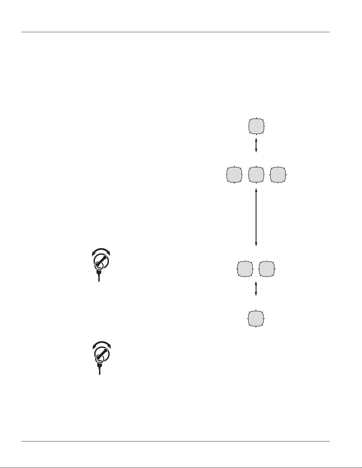
1 Flash
SERVICE
Short
Code 13
pause
(1/2 sec)
3 Flashes
SERVICE
SERVICE
SERVICE
Long Pause
(3-4 sec)
2x
off
on
5. To Retrieve Inactive Codes: Turn key on. Turn the
key off and on 4 times within five seconds ending
with the key in the on position. After 5 seconds, the
Service light begins flashing two-digit fault codes.
If no faults are active, the service light will flash
code 25 (no codes).
4x
off
on
• Two digit fault codes will be displayed in the gear
display. Some vehicle may be equipped with a service light.
Code 21
2 Flashes
SERVICE
1 Flash
SERVICE
SERVICE
Short
pause
(1/2 sec)
10
© 2013 Eaton. All rights reserved
2013.08.6
Page 16

TRTS0930 General Information | Fault Code Retrieval/Clearing
Clearing Fault Codes Manually
The following procedure clears all Inactive fault codes from
the TECU’s memory. Active fault codes are automatically
cleared when the fault has been corrected.
Note: You may use a PC-based service tool, such as Ser-
viceRanger, to clear fault codes.
1. Place shift lever in neutral.
2. Set parking brake.
3. Turn key on with engine off.
4. Turn key off and on 6 times within 5 seconds ending with key on.
6x
off
Note: If the codes have been successfully cleared, the
Service light will come on and stay on for five
seconds. The gear display will show 25 (no
codes).
5. Turn the key off and allow the system to power
down.
on
Retrieving Fault Codes with
ServiceRanger
This section determines if the TECU is communicating on
the vehicle's J1939 data link and if the component has set
any fault codes. Proper system operation requires the TECU
to communicate with other ECUs on the vehicle's J1939
data link.
Note: This procedure requires ServiceRanger 3.0 or later
and an approved RP1210A communications adapter
that supports J1939 communications.
Detecting Components
1. Connect the service PC to the vehicle's 9-way
J1939 diagnostic port connector with an approved
RP1210A communications adapter.
2. Start the ServiceRanger program and verify that a
connection has been established with the vehicle's
J1939 data link.
• If the TECU is not detected by ServiceRanger,
proceed to the Electrical Pretest procedure to
ensure the TECU has power, and that all components are properly connected the vehicle's
J1939 data link.
Viewing Fault Codes
View the Vehicle Fault Codes screen in ServiceRanger and
verify if any Active or Inactive codes have been set.
1. If an Active code is present, record the vehicle fault
information and proceed to Diagnostic Procedure
in this manual for the Active code. Do not clear any
codes at this time.
2. If only Inactive codes are present, record the vehicle fault information and clear all fault codes. Road
test the vehicle to verify proper operation.
2013.08.6
© 2013 Eaton. All rights reserved
11
Page 17

Fault Code Retrieval/Clearing | General Information TRTS0930
Clearing Fault Codes with ServiceRanger
After all repairs have been made and the system is functioning normally, clear all vehicle codes before placing the vehicle back into service.
Clearing Fault Code
1. Connect the service PC to the vehicle and start ServiceRanger.
2. View the Vehicle Fault Codes screen and select
Clear All.
3. Refresh the screen to verify all Inactive codes have
been cleared, and that no Active codes are present.
12
© 2013 Eaton. All rights reserved
2013.08.6
Page 18

TRTS0930 General Information | Fault Code Isolation Procedure Index
Fault Code Isolation Procedure Index
Fault Codes SPN PID SID FMI Description
11 629 254 12 No ECU operation
12 629 254 13, 14 Improper ECU configuration
13 751 231 8, 11 J1939 Shift Control device
14
(without Park
Pawl)
14
(with Park
Pawl)
15 751 18 9 HIL Shift Device communication
16 625 248 2 High Integrity Link (HIL)
17 1321 237 3, 4, 14 Start Enable Relay Coil
18 520200 34 9 ECA communication
19 520273 248 9 CAN ECA message
21 70 70 14 Auto Neutral Park Brake Switch
22 563 49 9, 14 ABS CAN message fault
25 NO CODES
26 522 55 10 Clutch slip
27 788 55 7, 13 Clutch disengagement
28 788 52,55 3, 4, 5, 7 Clutch system
29 969 372 4, 5 Remote throttle enable
31 1485 218 2, 3, 4, 5, 14 Momentary Engine Ignition Interrupt Relay
32 158 43 2 Loss of Switch Ignition power test
33 168 168 4 Low Battery voltage supply
34 168 168 14 Weak Battery voltage supply
35 639 231 2 J1939 communication link
36 639 231 14 J1939 engine message
37 627 251 5 Power supply
41 768 35 7 Range failed to engage
41 769 36 7 Range failed to engage
42 770 37 7 Splitter failed to engage
42 771 38 7 Splitter failed to engage
43 768 35 3, 4, 5 Range High Solenoid Valve
43 769 36 3, 4, 5 Range Low Solenoid Valve
44 787 54 3, 4, 5 Inertia Brake Solenoid Coil
45 787 54 7 Intertia Brake performance
46 770 37 3, 4, 5 Splitter Direct Solenoid Valve
751 18, 19 2, 3, 4, 5 Invalid Shift Lever voltage
18, 19 2, 3, 4, 5 Invalid Shift Lever voltage
(will show “F” in display)
(MEIIR)
2013.08.16
© 2013 Eaton. All rights reserved
13
Page 19

Fault Code Isolation Procedure Index | General Information TRTS0930
Fault Codes SPN PID SID FMI Description
46 771 38 3, 4, 5 Splitter Indirect Solenoid Valve
51 60 60 2, 3, 4, 10 Rail Position Sensor
52 59 59 2, 3, 4, 7 Gear Position Sensor
56 161 161 2, 3, 4, 5,10 Input Shaft Speed Sensor
57 160 160 2, 3, 4, 5 Main Shaft Speed Sensor
58 191 191 2, 3, 4, 5, 6, 8 Output Shaft Speed Sensor
61 772 39 1, 5, 6, 12 Rail Select Motor
63 773 40 1, 5, 6, 12 Gear Select Motor
64 788 34 2, 7, 12 ECA fault
65 5052 192 5, 2 ECA Speed Sensor fault
66 520271 34 3, 4 ECA Battery Voltage fault
67 520274 158 3, 4, 5 ECA Ignition Voltage fault
68 520274 227 14 Grade Sensor
68 520321 227 13, 14 Grade Sensor
71 560 60 7 Unable to disengage gear
72 772 59 7 Failed to select rail
73 781 58 7 Failed to engage gear
74 518 93 7 Engine speed response fault
74 898 190 7 Engine torque response fault
75* 560 60 14 Power down in gear
81 780 47 7 Gear engagement detected
83 751 18 14 Shift Lever missing
83 752 19 7, 12 Shift Lever missing
84 751 18 13 Shift Control device not configured
84 752 19 13 Park mechanism not calibrated
85 751 18 12 Shift Control device incompatible
99 781 58 14 Direction mismatch
* This code will only be set Inactive
• J1939 Source Address (SA) for Eaton transmissions is 3
• J1587 Module Identifier (MID) for Eaton transmissions is 130
14
© 2013 Eaton. All rights reserved
2013.08.16
Page 20

TRTS0930 General Information | Symptom-Driven Diagnostics Index
Symptom-Driven Diagnostics Index
Symptom Isolation Procedure
Unable to shift transmission with Up/Down button Up/Down Button Test
Engine starting system complaint Start Enable Relay Contact Test
No J1587 communication J1587 Data Link Test
Gear display shows a dash Front Box Control Test
AutoShift will not engage a gear from Neutral AutoShift Will Not Engage a Gear from Neutral Test
UltraShift DM will not engage a gear from Neutral UltraShift DM Will Not Engage a Gear from Neutral Test
UltraShift AW3 will not engage a gear from Neutral UltraShift AW3 Clutch Engagement Test
AutoShift AS3 shift complaint AutoShift AS3 Shift Complaint Test
UltraShift
DM shift complaint UltraShift DM Shift Complaint Test
UltraShift AW3 shift complaint UltraShift AW3 Shift Complaint Test
Shift Lever back light does not work Shift Lever Back Light Test
UltraShift PLUS will not engage a gear from Neutral UltraShift PLUS Will Not Engage a Gear from Neutral
Test
UltraShift PLUS shift complaint UltraShift PLUS Shift Complaint Test
2013.08.6
© 2013 Eaton. All rights reserved
15
Page 21

Product Diagnostic (PD) Mode | General Information TRTS0930
Product Diagnostic (PD) Mode
Product Diagnostic (PD) Mode
PD Mode is used to help diagnose Inactive codes that may
have been set during normal driving. This diagnostic mode
increases the sensitivity of the fault sensing capability
This procedure tests loose, degraded and intermittent connections. Use the Active Fault Isolation Procedure to guide
you to the wiring and connectors that are associated with
the Inactive fault codes. Flex the wiring harness and connectors and attempt to recreate the fault after activating PD
Mode.
PD Mode is only to be used by a trained service technician
in an authorized dealer.
This procedure is to be used prior to performing fault isolation procedures for component-type codes when there are
no Active codes present.
To enter PD Mode:
Note: Vehicle will not start in PD Mode. You must turn vehi-
cle key off to exit PD Mode.
1. Vehicle must be stationary, engine off, set vehicle
parking brake.
• If the fault is detected during PD Mode the gear display will display the active fault. The warning tone
will only sound when the fault is active and the tone
will stop when the fault is Inactive. The fault will
stay in the gear display until the system is powered
down.
Note: Active codes set during PD Mode will not be
stored as Inactive.
7. If a fault is detected, exit PD Mode and perform the
corresponding Fault Isolation Procedure.
8. To exit PD Mode, turn the key off.
PD Mode works with the following
Inactive codes:
11, 13, 14, 15,16, 17, 18, 19, 21, 22, 29, 33, 34, 35, 36, 43,
44, 46, 51, 52, 56, 57, 58, 61, 63, 65, 66, 67, 74, and 99.
2. Turn the key off and on 2 times, starting with key
on and ending with key on.
Note: Dash may display an 88 at key on. This is a nor-
mal power-up test of the display.
3. The gear display will flash a 25 then a solid PD
(Product Diagnostic Mode) and the mode will be
activated.
4. The service light shall flash code 25 once indicating
no codes. The service light shall then illuminate
solid to indicate PD Mode until such time that an
Active code is detected or PD Mode is exited.
5. Refer to PD Mode section in Fault Isolation procedure for the Inactive fault to be diagnosed.
6. PD will remain in gear display until an active fault
has been set during the PD Mode fault isolation
procedure.
16
© 2013 Eaton. All rights reserved
2013.08.16
Page 22

TRTS0930 General Information | Product Diagnostic (PD) Mode
2013.08.16
© 2013 Eaton. All rights reserved
17
Page 23

Electrical Pretest | Electrical Pretest Procedures TRTS0930
Electrical Pretest
Overview
The pretest does not relate to any specific fault code, but
must be completed before performing Fault Code Isolation
table procedures. The pretest verifies the batteries are fully
charged.
All Generation 3 products require the OEM to supply power
to the Electronic Control Unit (ECU) and to the optional
Electric Clutch Actuator (ECA).
Detection
There is no detection process specifically for the basic electrical supply; however, failures of this type are generally
detected by the transmission or driver as some other type
of fault code or symptom.
Fallback
There is no fallback for the electrical pretest; however, it
may affect other systems.
Possible Causes
The pretest can be used for:
• Low batteries
• Starter/Battery connections
• Main power harness to the Transmission Electronic
Control Unit (TECU)
Additional Tools
• Basic hand tools
• Eaton Test Adapter Kit
• Digital Volt/Ohm meter
• Troubleshooting Guide
• Battery Load tester
• ServiceRanger a PC-based service tool
18
© 2013 Eaton. All rights reserved
2013.08.23
Page 24

TRTS0930 Electrical Pretest Procedures | Electrical Pretest
J1
-+
1.
2.
Component Identification
TECU Power Harness
OEM is responsible for overcurrent protection on this circuit.
2013.08.23
1. 30 AMP Fuse
2. TECU Connector (Vehicle Interface)
© 2013 Eaton. All rights reserved
19
Page 25
Electrical Pretest | Electrical Pretest Procedures TRTS0930
Heavy-Duty Electric Clutch Actuator
(ECA) Power Harness
OEM is responsible for overcurrent protection on this circuit. ECA products are 12-volt only.
-+
1. 50 AMP Fuse
1.
J1
20
© 2013 Eaton. All rights reserved
2013.08.23
Page 26

TRTS0930 Electrical Pretest Procedures | Electrical Pretest
Heavy-Duty Electric Clutch Actuator
(ECA) Power Harness
Important: The TECU and ECA must be wired to a
non-switched power source at the battery. If a disconnect
switch is required, the recommended practice is to wait a
minimum of three minutes before using the disconnect
switch.
It is the OEM responsibility to provide power and ground to
the TECU and ECA from the battery which supplies the
starter.
The power (+) connection must include overload protection
per Federal Motor Carrier Safety Regulations, Section
393.31. The TECU main power and ground must be a direct
connection from the battery posts to the TECU connector.
At 120° C, these conductors must be able to carry 30 amps
@ 9 volts with no more than 0.05 ohms per wire (0.1 ohms
total) for a total voltage drop from the battery posts to the
TECU connector not to exceed 3.0 volts. ECA main power
and ground must be able to carry 50 amps @ 9 volts with
no more than 0.025 ohms per wire (.05 ohms total) at 120°
C. Duration of the 50 amp current draw will not exceed 20
milliseconds.
The main power 30-amp fuse connection for the TECU must
be identified with a tag at the battery.
The main power 50-amp fuse connection for the ECA must
be identified with a tag at the battery.
The battery positive post and negative post must be disconnected PRIOR to any type of welding on any Fuller Automated Transmission-equipped vehicles.
Removal of fuses is not recommended as the method of
disconnecting power from the ECU. Making and breaking a
circuit through tin plated terminals (e.g. ring terminals,
fuses, most connectors) will destroy the plating on the terminal. Opening a switch contact or the main power link is
the recommended method of interrupting power.
Application of more than 36 volts to the system (such as
jump-starting) will cause system shutdown and possible
electrical component damage.
Do not switch off the battery and ignition power and ground
to the TECU during the engine start process.
2013.08.23
© 2013 Eaton. All rights reserved
21
Page 27

Electrical Pretest | Electrical Pretest Procedures TRTS0930
R
ETRATST
T
AB
ERYP LUS2
RETRAT
SETTABRYM INUS2
RETRATSETTABRYM IN
US 1
RET
RAT
S
TTA
BERY
P LUS
1
+-
BATTERY
12 VOLT
+-
BATTERY
12 VOLT
+-
BATTERY
12 VOLT
+-
BATTERY
12 VOLT
RATS OT SREPMUJ LAUD - KNAB REP SEIRETTAB OWT - SKNA
B YRETTAB OWT
TER
REWOP 3 NEG
.SRIAP YB LELLARAP NI
DETCENNOC ERA SEIRETTAB
SUPPLIED BY
A SU
LP HTOB( RE
TRATS OT TSE
SOL
C YRETTAB
NDMINUS)
RETRATS
ET
TABRY
M I
NUS 1
RETRATSTTABERYP LUS1
+-
BATTERY
12 VOLT
+-
BATTERY
12 VOLT
+-
BATTERY
12 VOLT
+-
BATTERY
12 VOLT
AMG
LERAY
ENNOCSID HTIW KNAB REP SEIRETTAB OWT - SKNAB YRETTAB OWT CT
E
V DNA BA
C ROF
T
C
E
NNOCSID - SR
IA
P
Y
B LE
LLARA
P NI DETCENNOC ERA SEIRETTA
B H
ICL
E
START
-
PAC TNEMN
IATRET
NE DNA TRO
FMOC BAC
"EGRAHCSID PEE
D" S
EDIVORP RIA
P
DETCEN
NOCS
I
D ABILITY.
C DNA RETRATS OT TSESOLC TES YRETTAB MORF DEILPPUS REWOP 3 NEG
OMMONTO
CAB POWER
ETTAB UCE 3 NEGR
YMI
NUS
T
A
B
UCE 3 NEGTERYPL
U
S
ETTAB UCE 3 NEGRY
M
INU
S
RETRATSETTABRYM INUS 1
RETRATSTTABERYP LUS 1
+-
BATTERY
12 VOLT
+-
BATTERY
12 VOLT
+-
BATTERY
12 VOLT
+-
BATTERY
12 VOLT
IRETTAB RUOF - KNAB YRETTAB ENOES
REWOP 3 NEG .LELLARAP NI DETCENNOC ERA SEIRETTAB SUPPLIED FROM
HTOB( .REWOP BAC HTI
W RE
TRATS OT TSESOLC YRETTABPLU
S
AND MINUS)
TAB UCE 3 NEGTERYPLUS
ETTAB UCE 3 NEGRYM
I
NUS
TTAB BACERYPLUS
TAB UCE 3 NEGTE
R
YPLUS
TTAB BAC ERY PLUS
Preferred +12 Volt Connections
22
© 2013 Eaton. All rights reserved
2013.08.23
Page 28

TRTS0930 Electrical Pretest Procedures | Electrical Pretest
Preferred +12 Volt Connections
N
A
T
B UCE 3 NEGRY M
U
E
I
S
B UC
T
E 3 NEGTERY PLUS
A
T
+-
12 VOLT
BATTERY
+-
12 VOLT
BATTERY
EIRET
TAB ERY CLOOT TS
GEN 3 ECU BATTERY PLUS
+-
12 VOLT
BATTERY
RETRATS EHT OT TSESOLC ISCONNECT SW ITCH
+-
12 VOLT
BATTERY
NOITUBIRTSID REWOP M ODULE
+-
12 VOLT
BATTERY
+-
12 VOLT
BATTERY
P TA DETCENNOCSID ERA SEIRETTAB RSUPPLIED
+-
12 VOLT
BATTERY
CAB BATTERY PLUS
Starter Battery Plus
+-
12 VOLT
BATTERY
YRETTABM INU
AB RETRATSTTERYPL
S
TIWS TCENNOCSID EVITAGEN YRETTAB - SKNAB YRETTAB OWTCH
(POWER BUS AND
OVER CURRENT
DISTRIBUTION
DEVICES)
MODULE
POWER
+-
12 VOLT
BATTERY
WOL ROF DEZIMITPO HTGNEL DNA EZIS SELBAC .RETRATSVOLTAGEDROP
AB RETRATSTTERYPLU
TAB RETRATSTERY MINUS
TTAB NO DETCENNOC SUNIM DNA SULP REWOP ,LELLARAP NI DETCENNOC ERA S
+-
12 VOLT
BATTERY
STARTER
US
VE
EWOP 3 NEG .EDISNI DEROTS ELCIHEV NEHW NWOD REWO
T NOITCENNOC ELBAC ELCIHEV FO TNIOP TA NOITCENNOC EVITAGEN .
D O
S
S
E
TAB RETR
YMINU
ATSTER
TAB ELCIHE
RY MINUS
T
MBATTER
FRO
TAB UCE 3 NEGTERYPLUS
ETTAB UCE 3 NEGRYMINUS
EHT
S
Y
2013.08.23
GEN 3 ECU BATTERY MINUS
STARTER BATTERY CONNECTION
GEN 3 POWER PLUS AND MINUS CONNECTED ON BATTERY CLOSEST TO THE STARTER.
+-
12 VOLT
BATTERY
ONE BATTERY BANK - TWO BATTERIES
BATTERIES ARE CONNECTED IN PARALLEL. GEN 3 POWER SUPPLIED FROM
BATTERY CLOSEST TO STARTER WITH CAB POWER. (BOTH PLUS AND MINUS)
+-
12 VOLT
BATTERY
STARTER BATTERY MINUS
CAB BATTERY PLUS
GEN 3 ECU BATTERY PLUS
STARTER BATTERY PLUS 1
GEN 3 ECU BATTERY MINUS
STARTER BATTERY MINUS 1
© 2013 Eaton. All rights reserved
23
Page 29

Electrical Pretest | Electrical Pretest Procedures TRTS0930
STARTER BATTERY PLUS
2
STARTER BATTERY MINUS
2
STARTER BATTERY MINUS
1
+ -
BATTERY
12 VOLT
+ -
BATTERY
12 VOLT
+ -
BATTERY
12 VOLT
+ -
BATTERY
12 VOLT
TWO BATTERY BANKS - TWO BATTERIES IN SERIES PER BANK - DUAL JUMPERS TO
STARTER
BATTERIES ARE CONNECTED IN SERIES/PARALLEL BY PAIRS. GEN 3 POWER
SUPPLIED BY BATTERY CLOSEST TO STARTER (BOTH PLUS AND MINUS)
+ -
BATTERY
12 VOLT
+ -
BATTERY
12 VOLT
+ -
BATTERY
12 VOLT
+ -
BATTERY
12 VOLT
MAG
RELAY
TWO BATTERY BANKS - TWO BATTERIES PER BANK WITH DISCONNECT
BATTERIES ARE CONNECTED IN SERIES/PARALLEL BY PAIRS - DISCONNECT FOR CAB AND VEHICLE
START - DISCONNECTED PAIR PROVIDES "DEEP DISCHARGE" CAB COMFORT AND ENTERTAINMENT
CAPABILITY. GEN 3 POWER SUPPLIED FROM BATTERY SET CLOSEST TO STARTER AND COMMON TO
CAB POWER
GEN 3 ECU BATTERY
PLUS
GEN 3 ECU BATTERY
MINUS
STARTER BATTERY MINUS
1
STARTER BATTERY PLUS
1
+ -
BATTERY
12 VOLT
+ -
BATTERY
12 VOLT
+ -
BATTERY
12 VOLT
+ -
BATTERY
12 VOLT
ONE BATTERY BANK - FOUR BATTERIES - ONE CABLE PAIR TO STARTER
BATTERIES ARE CONNECTED IN SERIES/PARALLEL BY PAIRS. GEN 3 POWER
SUPPLIED FROM BATTERY CLOSEST TO STARTER WITH CAB POWER. (BOTH PLUS
AND MINUS)
GEN 3 ECU BATTERY
PLUS
GEN 3 ECU BATTERY
MINUS
CAB BATTERY
PLUS
STARTER BATTERY PLUS
1
STARTER BATTERY MINUS
1
STARTER BATTERY PLUS
1
GEN 3 ECU BATTERY
MINUS
CAB BATTERY
PLUS
GEN 3 ECU BATTERY
PLUS
Preferred +24 Volt Connections
24
© 2013 Eaton. All rights reserved
2013.08.23
Page 30

TRTS0930 Electrical Pretest Procedures | Electrical Pretest
+-
BATTERY
12 VOLT
+-
BATTERY
12 VOLT
+-
BATTERY
12 VOLT
+-
BATTERY
12 VOLT
TWO BATTERY BANKS - BATTERY NEGATIVE DISCONNECT SWITCH
BATTERIES ARE DISCONNECTED AT POWER DOWN WHEN VEHICLE STORED INSIDE. GEN 3 POWER SUPPLIED FROM BATTERY
CLOSEST TO THE STARTER. NEGATIVE CONNECTION AT POINT OF VEHICLE CABLE CONNECTION TO DISCONNECT SWITCH
BATTERY
MINUS
STARTER BATTERY
PLUS
STARTER BATTERY
MINUS
VEHICLE BATTERY
MINUS
GEN 3 ECU BATTERY
PLUS
GEN 3 ECU BATTERY
MINUS
STARTER BATTERY
MINUS
STARTER BATTERY
PLUS
+-
BATTERY
12 VOLT
+-
BATTERY
12 VOLT
+-
BATTERY
12 VOLT
+-
BATTERY
12 VOLT
POWER DISTRIBUTION MODULE
BATTERIES ARE CONNECTED IN SERIES/PARALLEL, POWER PLUS AND MINUS CONNECTED ON BATTERY CLOSEST TO THE
STARTER. CABLES SIZE AND LENGTH OPTIMIZED FOR LOW VOLTAGE DROP
GEN 3 ECU BATTERY
PLUS
GEN 3 ECU BATTERY
MINUS
POWER
DISTRIBUTION
MODULE
(POWER BUS AND
OVER CURRENT
DEVICES)
STARTER BATTERY
MINUS
STARTER BATTERY
PLUS
STARTER
CAB BATTERY
PLUS
GEN 3 ECU BATTERY
MINUS
GEN 3 ECU BATTERY
PLUS
STARTER BATTERY CONNECTION
GEN 3 POWER PLUS AND MINUS CONNECTED ON BATTERY CLOSEST TO THE STARTER.
Preferred +24 Volt Connections
© 2013 Eaton. All rights reserved
2013.08.23
25
Page 31

Electrical Pretest | Electrical Pretest Procedures TRTS0930
TECU Ignition Circuit
1.
J1
35
4.
37
13
35
1. TECU connector (vehicle interface)
2. 10 AMP only, manual resetting circuit breaker OR
10 AMP fuse
3. Ignition Key Switch
29 30
23
14
15
7389
1
24 25
16
2
2.
3.
31
17
32 33
26
27 28
19
18
10611 12
5
4
34
20
38
21
22
36
Note: Run to main power lead that feeds the ignition
bus (OEM responsible for overcurrent protection
on this line)
4. TECU Connector (vehicle interface) front view
From To
J1-35 VIGN
Battery and ignition power and ground to the TECU must
not be switched off during the engine start process.
26
© 2013 Eaton. All rights reserved
2013.08.23
Page 32

TRTS0930 Electrical Pretest Procedures | Electrical Pretest
+ Battery
10
11
C
D
B
F
G
A
A
F
J
E
G
H
D
C
B
J1
J1939 Low
J1939 High
1.
2.
3.
J1939 Data Link
1. TECU connector (vehicle interface)
2. J1587 Data Link
3. 9-Way, for transmission diagnostics
J1939 Troubleshooting
1. Check the resistance of the J1939 Data Link.
2. Key off. Measure resistance between the 9-way
diagnostic connector Pin C and Pin D and record
the reading. The reading should be 60 ohms of
resistance (between 50 and 70.)
3. Check resistance between Pin C and Pin A and the
resistance between Pin D and Pin A. These two
readings should be 10K ohms or greater (open circuit).
Note: Pin C = J1939+, Pin D = J1939-, Pin A is a chas-
sis ground
• If an Inactive data link fault code is being reported
by the TECU, See “Product Diagnostic (PD) Mode”
on page 16. PDM should be utilized before any fur-
ther steps are taken.
2013.08.23
© 2013 Eaton. All rights reserved
27
Page 33

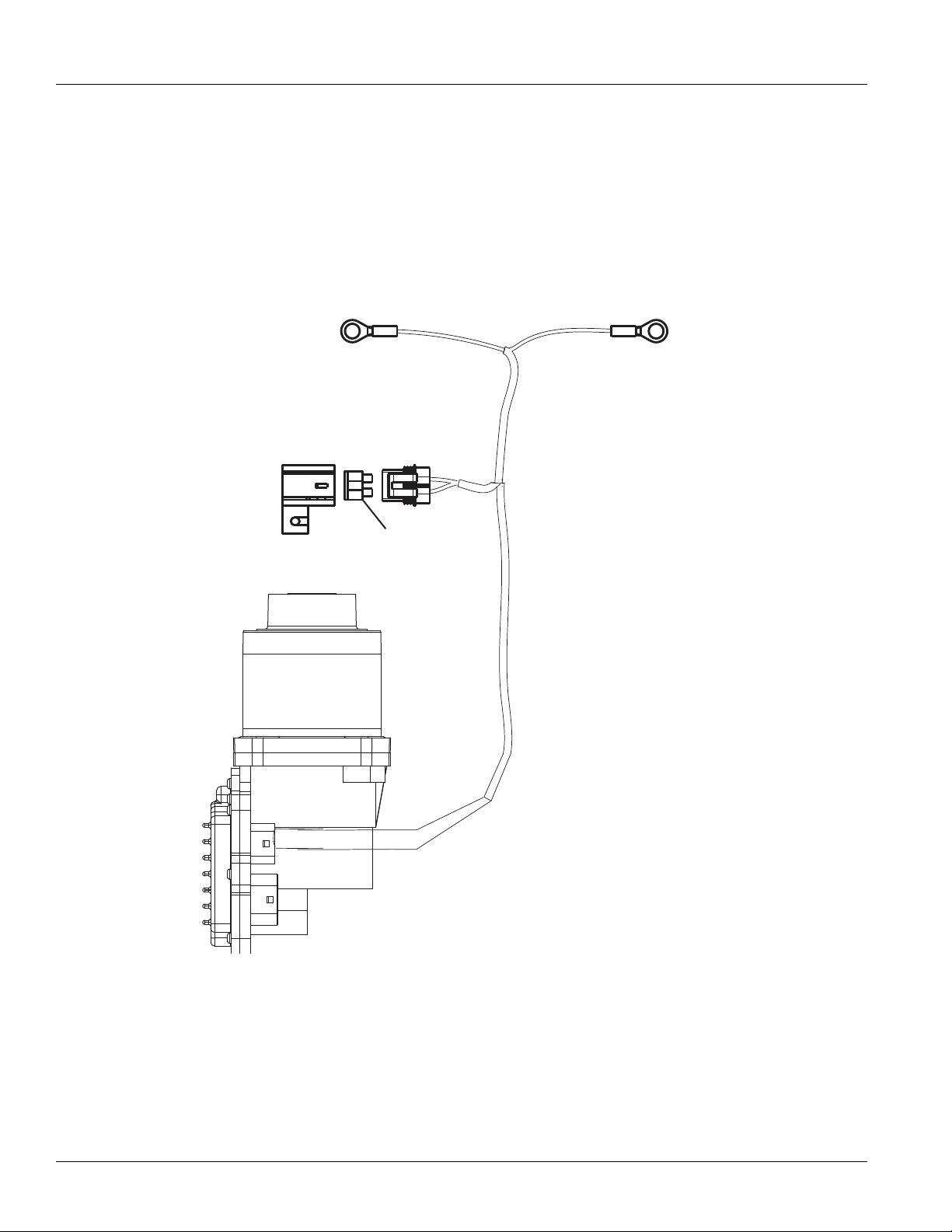
Electrical Pretest | Electrical Pretest Procedures TRTS0930
50 AMP fuse
Battery power
(Non-switched power)
run to Battery
B
C
ECA 3-Way
Connector
ECA
A
B
C
+
–
+
–
Batteries
30 AMP fuse
Transmission ECU
4-Pin Diagnostic Port
(Located at the left rear
corner of the transmission.)
4-Pin Diagnostics Port
4-way
B - Service Bat. +
C - Service Bat. A - Service Ignition +
VOLTS
V
COM
A
Battery Negative Post
B
A
D
C
Warning! - Do Not Load Test at Diagnostic Port
Electrical Pretest
Purpose: Measure battery voltage. Visually inspect
the batteries, inline fuse and power and ground
A
supplies at the batteries and ECA (if equipped).
1. Key off.
Purpose: Verify proper ground path between the
batteries and the transmission harness 4-way diag-
B
nostic connector.
2. Remove and clean all battery and battery-to-frame
connections.
3. Remove and clean ground supply to engine ECU.
4. Inspect starter/battery and inline 30 amp fuse
holder connections for corrosion or damaged contacts. Also, inspect the 50 amp fuse holder on vehicles equipped with an Electronic Clutch Actuator
(ECA).
5. Measure voltage across batteries.
• If voltage is 11 to 13 volts on a 12- volt system
or 22 to 26 on a 24 volt system, refer to OEM
guidelines for battery load test. Repair or
replace batteries as required. Go to Step
B.
1. Locate diagnostic port on Transmission Harness.
2. Key on.
3. Measure voltage between Pin C and the battery
negative post.
• If voltage is 0.70 volts or less, go to Step
C.
• If voltage is outside of range, repair battery
ground supply to Transmission Electrical Control Unit (TECU). Repeat test.
28
• If voltage is outside of range, repair or replace
batteries and charging system as required.
Repeat this step.
© 2013 Eaton. All rights reserved
2013.08.23
Page 34

TRTS0930 Electrical Pretest Procedures | Electrical Pretest
4-Pin Diagnostics Port
4-way
B - Service Bat. +
C - Service Bat. A - Service Ignition +
B
A
D
C
4-Pin Diagnostic Port
(Located at the left rear
corner of the transmission.)
Warning! - Do Not Load Test at Diagnostic Port
!
Purpose: Measure proper battery voltage at the
C
transmission harness 4-way diagnostic connector.
1. Locate diagnostic port on Transmission Harness.
2. Key on.
3. Measure voltage between Pin B and Pin C.
• If voltage is within 0.6 volts of battery voltage,
go to Step
D.
• If voltage is outside of range, Repair battery
power supply to TECU. Fuse may be blown.
Repeat test.
Purpose: Measure proper ignition voltage at the
D
transmission harness 4-way diagnostic connector.
1. Key on.
Warning: Do not load test at the diagnostic port.
2. Measure voltage between Pin A and Pin C.
Warning! - Do Not Load Test at Diagnostic Port
4-Pin Diagnostics Port
B
A
D
C
4-way
4-Pin Diagnostic Port
(Located at the left rear
corner of the transmission.)
B - Service Bat. +
C - Service Bat. A - Service Ignition +
• If voltage is within 0.6 volts of battery voltage,
For non-ECA products, test complete. See
“Diagnostic Procedures” on page 6. Go to
Step
E.
• If voltage is outside of range, repair ignition
power supply to TECU. Fuse may be blown.
Repeat test.
2013.08.23
© 2013 Eaton. All rights reserved
29
Page 35

Electrical Pretest | Electrical Pretest Procedures TRTS0930
Transmission ECU
30
29
29
F
G
F
G
50 AMP fuse
Battery power
(Non-switched power)
run to Battery
Engine Flywheel Speed Sensor
(Eaton Supplied)
B
C
Terminating
Resistor
ECA 8-Way
Connector
ECA 3-Way
Connector
ECA
13
30
E C
E C
B A
B A
A
B
C
Purpose: Measure battery voltage supplied to the
E
Electronic Clutch Actuator (ECA).
1. Key off.
2. Disconnect battery negative.
3. Disconnect ECA 3-way connector.
4. Reconnect battery negative.
5. Measure voltage between Pin B and Pin C of 3-way
connector.
• If voltage is within 0.6 volts of battery voltage,
test complete. See “Diagnostic Procedures” on
page 6.
• If voltage is outside of range, repair battery
power supply to ECA. Fuse may be blown.
Repeat test.
30
© 2013 Eaton. All rights reserved
2013.08.23
Page 36

TRTS0930 Electrical Pretest Procedures | Electrical Pretest
2013.08.23
© 2013 Eaton. All rights reserved
31
Page 37

Power-Up Sequence Test | Electrical Pretest Procedures TRTS0930
Power-Up Sequence Test
Overview
This test does not relate to any specific fault code, but must
be completed if the self check fails at power-up.
Detection
The TECU checks the program memory every time the key
is turned on.
Fallback
This causes an In-Place fallback while moving and a
self-check failure if it occurs during power-up.
Possible Causes
This fault code can be caused by any of the following:
• Vehicle Harness
• Shift Control Device
• TECU
32
© 2013 Eaton. All rights reserved
2013.08.23
Page 38

TRTS0930 Electrical Pretest Procedures | Power-Up Sequence Test
4.
VOLUME
CONTROL
SERVICE
SHIFT
Eaton Fuller
Transmissions
L
H
D
N
R
1.
2.
3.
Component Identification
1. Side view of pushbutton shift control
2. Transmission controller 30-way connector
3. Top view of pushbutton shift control
4. Eaton Cobra Lever
2013.08.23
© 2013 Eaton. All rights reserved
33
Page 39

Power-Up Sequence Test | Electrical Pretest Procedures TRTS0930
Power-Up Sequence Test
Purpose: Measure battery voltage. Visually inspect
the batteries, inline fuse and power and ground
A
supplies at the batteries.
1. Key off.
2. Remove and clean all battery and battery-to- frame
connections.
3. Remove and clean ground supply to engine ECU.
4. Inspect starter/battery and inline 30-amp fuse
holder connections for corrosion or damaged contacts.
5. Measure voltage across batteries.
• If voltage is 11 to 13 volts on a 12-volt system
or 22 to 26 on a 24-volt system, proceed with
battery load test. Repair or replace batteries as
required. Go to Step
• If voltage is outside of range, repair or replace
batteries and charging system as required.
Repeat this step.
B.
Purpose: Measure proper battery voltage at the
C
transmission harness 4-way diagnostic connector.
1. Locate diagnostic port on Transmission Harness.
2. Key on.
3. Measure voltage between Pin B and Pin C.
Warning: Do not load test at the diagnostic port.
!
• If voltage is within 0.6 volts of battery voltage,
go to Step
• If voltage is outside of range, repair battery
power supply to TECU. Fuse may be blown.
Repeat test.
Purpose: Measure proper ignition voltage at the
D
transmission harness 4-way diagnostic connector.
D.
Purpose: Verify proper ground path between the
batteries and the transmission harness 4-way diag-
B
nostic connector.
1. Locate diagnostic port on Transmission Harness.
2. Key on.
3. Measure voltage between Pin C and the battery
negative post.
• If voltage is 0.70 volts or less, go to Step
• If voltage is outside of range, repair battery
ground supply to TECU. Repeat test.
C.
1. Key on.
2. Measure voltage between Pin A and Pin C.
• If voltage is within 0.6 volts of battery voltage,
go to Step
• If voltage is outside of range, repair Ignition
power supply to ECU. Fuse may be blown.
Repeat test.
E.
34
© 2013 Eaton. All rights reserved
2013.08.23
Page 40

TRTS0930 Electrical Pretest Procedures | Power-Up Sequence Test
Purpose: Visually identify if the vehicle is equipped
E
with a shift lever or push button.
1. Is vehicle equipped with an Shift Lever?
• If vehicle is not equipped with a Shift Lever, go
to Step
• If vehicle is equipped with a Shift Lever, go to
Step
Purpose: Visually identify if the push button is an
Eaton built push button or an OEM built J1939
F
push button.
1. Is it an Eaton Push Button or OEM J1939 Shift
Device?
• If an Eaton Push Button Shift Control, go to
Step
• If an OEM J1939 Shift Device, refer to OEM for
troubleshooting procedures.
F.
K.
G.
Purpose: Visually observe the Service light during
G
key-on power up.
1. Key on.
2. Observe Service light.
Note: If Service light is flashing, go to Diagnostics
Procedure.
• If Service light illuminates for 1 second and
turns off, test complete.
• If Service light never lights, go to Step
• If Service light is on steady, replace Shift Con-
trol. Go to Step V.
Purpose: Measure the voltage supply at the Shift
H
Control device.
1. Key off.
2. Disconnect Shift Control 30-way connector.
H.
3. Key on.
4. Measure voltage between Pin C1 and Pin J3 on the
Shift Control 30-way.
• If voltage is within 1 volt of battery voltage
replace Shift Control
• If voltage is outside of range, go to Step I.
. Go to Step V.
2013.08.23
© 2013 Eaton. All rights reserved
35
Page 41

Power-Up Sequence Test | Electrical Pretest Procedures TRTS0930
Purpose: Verify that a proper ground path is being
supplied to the Shift Control Device through the Ve-
I
hicle Harness and test for a short to ground.
1. Key off.
2. Disconnect negative battery cable.
3. Disconnect 38-way Vehicle Harness from TECU.
4. Measure resistance between TECU Pin 25 and Shift
Control connector Pin J3 and from then from Pin
J3 to ground.
• If resistance from Pin 25 to J3 is
0 to 0.3 ohms and resistance from J3 to
ground is OL / Open, go to Step
• If resistance is outside of range, repair the
Vehicle Harness. Go to Step
J.
V.
Purpose: Visually identify if the shift lever is an Ea-
K
ton built shift lever or an OEM built shift lever.
1. Is vehicle equipped with an Eaton supplied Shift
Lever or an OEM supplied Shift Lever.
• If Eaton Cobra Lever, go to Step
• If OEM Shift Lever, go to Step R.
Purpose: Visually observe the Service light during
L
key-on power up.
1. Key on.
2. Observe Service light.
Note: If Service light is flashing, See “Diagnostic
Procedures” on page 6.
L.
Purpose: Measure the resistance of the ignition
voltage supply wire to the Shift Control Device
J
through the Vehicle Harness and test for a short to
ground.
1. Measure resistance between TECU Pin 31 and Shift
Control connector Pin C1 and then from Pin C1 to
ground.
• If resistance from Pin 31 to C1 is 0 to 0.3
ohms and resistance from C1 to ground is 10K
or OL, replace the TECU. Go to Step
• If resistance is outside of range, repair the
Vehicle Harness. Go to Step
V.
V.
• If Service light illuminates for 1 second and
turns off, test complete.
• If Service light never comes on, go to Step
• If Service light is on steady, go to Step M.
O.
36
© 2013 Eaton. All rights reserved
2013.08.23
Page 42

TRTS0930 Electrical Pretest Procedures | Power-Up Sequence Test
Purpose: Measure the voltage supply to the Service
M
light during key-on power up.
1. Disconnect Shift Lever 8-way connector.
2. Key on.
3. Measure voltage at Pin 6 and ground.
• If voltage is within 2 volts of battery voltage for
one second, then 0 volts, replace the Eaton
Cobra Lever
• If voltage is constant, go to Step N.
Purpose: - Test the Service light voltage supply for
N
short to power through the Vehicle Harness.
1. Key off.
2. Disconnect negative cable.
3. Disconnect 38-way Vehicle Harness connector.
4. Measure resistance between Pin 6 and Pin 4.
• If resistance is OL, replace the:
- Medium-Duty Transmission Electronic Control Unit (TECU)
- Heavy-Duty Transmission Electronic Control Unit (TECU)
Go to Step V.
• If resistance is less than 10K, repair the Vehi-
cle Harness and go to Step
. Go to Step V.
V.
Purpose: Measure the voltage supply to the Service
O
light during key-on power up.
1. Key off.
2. Disconnect Shift Lever 8-way connector.
3. Key on.
4. Measure voltage between Pin 3 and Pin 6.
• If within 1 volt of battery replace Eaton Cobra
Lever, go to Step V.
• If voltage is outside of range, go to Step N.
Purpose: Verify that a proper ground path is being
supplied to the Shift Lever through the Vehicle Har-
P
ness and test for a short to ground.
1. Key off
2. Disconnect 38-way Vehicle Harness connector on
TECU.
3. Measure resistance between Pin 3 on the 8-way
connector and Pin 25 on the 38-way connector and
from Pin 25 to ground.
Note: On Peterbilt disconnect Gear Display,
• If resistance between Pin 3 and Pin 25 is 0 to
0.3 ohms and resistance from Pin 25 to
ground is OL, go to Step
• If resistance is outside of range, repair the
Vehicle Harness between the Vehicle Harness
38-way connector Pin 25 and Vehicle Harness
8-way connector Pin 3. Go to Step
Q.
V.
2013.08.23
© 2013 Eaton. All rights reserved
37
Page 43

Power-Up Sequence Test | Electrical Pretest Procedures TRTS0930
Purpose: Measure the resistance of the ignition
voltage supply to the Shift Lever through the Vehi-
Q
cle Harness and test for a short to ground.
1. Key off.
2. Measure resistance between:
- Vehicle Harness 38-way connector Pin 31 and
Vehicle Harness 8-way connector Pin 4
- Vehicle Harness 38-way connector Pin 31 and
ground
• If resistance between Pin 31 and Pin 4 is 0 to
0.3 ohms and if resistance between Pin 31 and
ground is OL, replace the:
- Medium-Duty Transmission Electronic Control Unit (TECU)
- Heavy-Duty Transmission Electronic Control Unit (TECU)
Go to Step V.
• If any of the above conditions are not met,
replace the Vehicle Harness between Vehicle
Harness 38-way connector Pin 31 and Vehicle
Harness 8-way connector Pin 4. Go to Step
V.
Purpose: Measure the voltage supply to the Service
R
light during key-on power up.
1. Key off.
2. Locate Service light connector on Vehicle Harness.
3. Key on.
4. Measure voltage across Pin A and Pin B on the Ser-
vice light connector
• If voltage is within 2 volts of battery voltage for
1 second, then 0 volts, test complete.
• If no voltage is measured, go to Step
• If voltage is within 2 volts of battery voltage
continuously, go to Step
T.
S.
38
© 2013 Eaton. All rights reserved
2013.08.23
Page 44

TRTS0930 Electrical Pretest Procedures | Power-Up Sequence Test
Purpose: Measure the resistance of the service
light supply wire to the Shift Lever through the Ve-
S
hicle Harness and test for a short to ground.
1. Key off.
2. Disconnect negative battery cable.
3. Disconnect 38-way connector.
4. Measure resistance from Pin A of the OEM connec-
tor to Pin 23 of the 38-way and from Pin 23 to
ground.
• If resistance from Pin A to Pin 23 is 0 to 0.3
ohms and resistance to ground is 10K or
greater, replace the:
- Medium-Duty Transmission Electronic Control Unit (TECU)
- Heavy-Duty Transmission Electronic Control Unit (TECU)
Go to Step V.
• If resistance is outside of range, repair the
Vehicle Harness and go to Step
V.
Purpose: Test for a short to power at the Shift Le-
T
ver Service light.
1. Key off.
2. Disconnect negative battery cable.
3. Disconnect TECU 38-way connector.
4. Measure voltage across Service light connector Pin
A and Pin B.
• If no voltage is measured, replace the:
- Medium-Duty Transmission Electronic Control Unit (TECU)
- Heavy-Duty Transmission Electronic Control Unit (TECU)
Go to Step V.
• If voltage is within 2 volts of battery voltage,
repair Vehicle Harness as required. Go to Step
V.
Purpose: Verify that the system will properly power
V
up.
1. Key off.
2. Reconnect all connectors and the negative battery
cable.
3. Key on.
• If Power-Up Sequence Test completes, test
complete.
• If Power-Up Sequence Test fails go to Step
find error in testing.
A.
2013.08.23
© 2013 Eaton. All rights reserved
39
Page 45

Fault Code 11 - No TECU Operation | Fault Isolation Procedures TRTS0930
Fault Code 11 - No TECU Operation
J1939: SA 3 SPN 629 FMI 12
J1587: MID130 PID FMI 12
Overview
This fault code indicates an internal failure of the Transmission Electronic Control Unit (TECU).
Detection
The TECU checks the program memory every time the key
is turned on and throughout operation. If the TECU is able
to detect a failure within its own memory, it sets this fault
code.
Fallback
This fault causes a vehicle In Place fallback while moving
and a self-check failure if it occurs during power-up.
Possible Causes
This fault code can be caused by the following:
• TECU
40
© 2013 Eaton. All rights reserved
2013.08.23
Page 46

TRTS0930 Fault Isolation Procedures | Fault Code 11 - No TECU Operation
1.
Component Identification
1. TECU
2013.08.23
© 2013 Eaton. All rights reserved
41
Page 47

Fault Code 11 - No TECU Operation | Fault Isolation Procedures TRTS0930
Fault Code 11 - No TECU Operation
Purpose: Check for active or Inactive fault codes
A
1. Key on.
2. Retrieve codes. See “Fault Code Retrieval/Clearing”
on page 10.
• If Fault Code 11 is Active, replace the:
- Medium-Duty Transmission Electronic Control Unit (TECU)
- Heavy-Duty Transmission Electronic Control Unit (TECU)
• If Fault Code 11 is Inactive, test complete.
42
© 2013 Eaton. All rights reserved
2013.08.23
Page 48

TRTS0930 Fault Isolation Procedures | Fault Code 11 - No TECU Operation
2013.08.23
© 2013 Eaton. All rights reserved
43
Page 49

Fault Code 12 - Improper ECU Configuration | Fault Isolation Procedures TRTS0930
Fault Code 12 - Improper ECU Configuration
J1939: SA 3 SPN 629 FMI 13,14
Overview
This fault code indicates the Transmission Electronic Control Unit (TECU) is not reading valid information from memory, including the transmission table and calibration values.
Detection
The TECU checks the configuration every time the key is
turned on. If the transmission is not able to detect the
proper configuration, it sets this fault code.
Fallback
This fault causes a power up no crank.
Possible Causes
This fault code can be caused by the following:
• Improper TECU configuration software
44
© 2013 Eaton. All rights reserved
2013.08.23
Page 50

TRTS0930 Fault Isolation Procedures | Fault Code 12 - Improper ECU Configuration
1.
Component Identification
1. TECU
2013.08.23
© 2013 Eaton. All rights reserved
45
Page 51

Fault Code 12 - Improper ECU Configuration | Fault Isolation Procedures TRTS0930
Fault Code 12 - Improper ECU Configuration
Purpose: Check for active or Inactive fault codes.
A
1. Key on.
2. Retrieve codes. See “Fault Code Retrieval/Clearing”
on page 10.
• If Fault Code 12 is Active, Customer - Call
Eaton at 1-800-826-HELP (4357). CSC - Call
Technician Service.
• If Fault Code 12 is Inactive, test complete.
46
© 2013 Eaton. All rights reserved
2013.08.23
Page 52

TRTS0930 Fault Isolation Procedures | Fault Code 12 - Improper ECU Configuration
2013.08.23
© 2013 Eaton. All rights reserved
47
Page 53

Fault Code 13 - J1939 Shift Control Device | Fault Isolation Procedures TRTS0930
Fault Code 13 - J1939 Shift Control Device
J1587: MID130 PID 231 FMI 8, 11
J1939: SA 3 SPN751 FMI 8, 11
Overview
This fault indicates communication has been lost, or does
not correspond with the neutral request input from the
J1939 Shift Device.
When troubleshooting an Inactive code, See “Product Diagnostic (PD) Mode” on page 16.
Detection
Starting at key on and throughout operation, the Transmission Electronic Control Unit (TECU) constantly monitors
communication with the J1939 Shift Device. If a neutral
request from the J1939 Shift Device does not match the
neutral signal or is not received from the J1939 Shift
Device, Fault Code 13 is set.
Fallback
This fault causes a downshift-only fallback. Once the transmission re-engages the start gear, there will be no upshifts
as long as the code is active.
Possible Causes
This fault code can be caused by the following:
• OEM J1939 Shift Control Device
• Vehicle Harness
48
© 2013 Eaton. All rights reserved
2013.08.23
Page 54

TRTS0930 Fault Isolation Procedures | Fault Code 13 - J1939 Shift Control Device
J1
J1939
16
17
1.
2.
3.
4.
5.
Component Identification
1. TECU Connector (vehicle interface)
2. Bulkhead connector located at firewall
3. OEM J1939 Shift Device
4. Battery Power (Non-switches power run to battery
or starter)
5. Switched Power
2013.08.23
© 2013 Eaton. All rights reserved
49
Page 55

Fault Code 13 - J1939 Shift Control Device | Fault Isolation Procedures TRTS0930
OHMS
V
COM
A
OHMS
V
COM
A
31
24 25
29 30
15 16
26
20
34
27 28
32 33
18 19
7389
12 6
11 12
45
22
21
38
36
37
13 14
35
10
17
23
31
24 25
29 30
15 16
26
20
34
27 28
32 33
18 19
7389
12 6
11 12
45
22
21
38
36
37
13 14
35
10
17
23
J1939
Fault Code 13 - J1939 Shift Control Device
Purpose: Verify continuity of Neutral Request Sig-
A
nal wire
1. Key off.
2. Disconnect negative battery cable.
3. Disconnect Vehicle Harness 38-way connector.
4. Measure resistance between 38-way connector Pin
16 and corresponding OEM pin at J1939 Shift
Device and Pin 16 and ground (see OEM wiring for
correct pin location)
OHMS
V
29 30
37
13 14
35
37
13 14
35
31
24 25
23
17
15 16
7389
12 6
29 30
31
24 25
23
15 16
17
7389
12 6
32 33
26
27 28
18 19
10
11 12
45
32 33
26
27 28
18 19
10
11 12
45
34
38
22
21
20
36
34
38
20
22
21
36
COM
J1939
OHMS
V
• If resistance is 0 to 0.3 ohms between Pin 16
and the corresponding OEM pin and resistance
to ground is 10K ohms or greater, go to Step
B.
• If resistance is out of range, replace the:
- Medium-Duty Transmission Harness
- Heavy-Duty Transmission Harness
Go to Step V.
Purpose: Verify continuity of Neutral Request Re-
B
turn wire
1. Measure resistance between 38-way connector Pin
17 and corresponding OEM pin at J1939 Shift
Device and Pin 17 and ground (see OEM wiring for
correct pin location).
A
A
COM
• If resistance is 0 to 0.3 ohms between Pin 17
and the corresponding OEM pin and resistance
to ground is 10K ohms or greater, problem
exists with the J1939 Shift Device, or J1939
Shift Device power, ground or data link wiring.
Contact your OEM for repair strategy. Go to
Step
V.
• If resistance is out of range, replace the:
- Medium-Duty Transmission Harness
- Heavy-Duty Transmission Harness
Go to Step V.
50
© 2013 Eaton. All rights reserved
2013.08.23
Page 56

TRTS0930 Fault Isolation Procedures | Fault Code 13 - J1939 Shift Control Device
Purpose: Verify repair.
V
1. Key off.
2. Reconnect all connectors and the negative battery
cable.
3. Key on.
4. Clear codes. See “Fault Code Retrieval/Clearing” on
page 10.
5. Drive vehicle and attempt to reset the code.
6. Check for codes. See “Fault Code Retrieval/Clear-
ing” on page 10.
• If no fault codes, test complete.
• If Fault Code 13 appears go to Step
error in testing.
• If fault code other than 13 appears, See “Fault
Code Isolation Procedure Index” on page 13.
A. to find
2013.08.23
© 2013 Eaton. All rights reserved
51
Page 57

Fault Code 14 - Invalid Shift Lever Voltage (without Park Pawl) | Fault Isolation Procedures TRTS0930
Fault Code 14 - Invalid Shift Lever Voltage (without Park Pawl)
J1587: MID 130 SID 18, 19 FMI 2, 3, 4, 5
J1939: SA 3 SPN 751 FMI 2, 3, 4, 5
Overview
This fault code indicates an electrical failure of the Eaton
Cobra Lever or OEM Shift Lever.
When troubleshooting an Inactive code See “Product Diagnostic (PD) Mode” on page 16.
Detection
Starting at key on and throughout operation the Transmission Electronic Control Unit (TECU) constantly monitors the
signal from the Park Pawl Position Sensor. The transmission monitors both sensor signals, if one signal to the TECU
is out of range the code will set.
Fallback
This fault may cause a downshift only fallback mode. The
transmission will re-engage the start gear when returned to
a stop, but will not upshift as long as the code is active.
Possible Causes
This fault code can be caused by any of the following:
• Eaton Cobra Lever or OEM Shift Lever
• Vehicle Harness
• TECU
52
© 2013 Eaton. All rights reserved
2013.08.23
Page 58

TRTS0930 Fault Isolation Procedures | Fault Code 14 - Invalid Shift Lever Voltage (without Park Pawl)
1.
2.
Component Identification
1. Eaton Cobra Lever 8-way connector
2. TECU 38-way connector
2013.08.23
© 2013 Eaton. All rights reserved
53
Page 59

Fault Code 14 - Invalid Shift Lever Voltage (without Park Pawl) | Fault Isolation Procedures TRTS0930
OHMS
V
COM
A
OHMS
V
COM
A
31
24 25
29 30
15 16
26
20
34
27 28
32 33
18 19
7389
12 6
11 12
45
22
21
38
36
37
13 14
35
10
17
23
1
2
3
4
5
6
7
8
31
24 25
29 30
15 16
26
20
34
27 28
32 33
18 19
7389
12 6
11 12
45
22
21
38
36
37
13 14
35
10
17
23
Fault Code 14 - Invalid Shift Lever Voltage (without Park Pawl)
Purpose: Visually identify the lever type: Eaton or
A
OEM manufactured.
1. Is vehicle equipped with an Eaton supplied Shift
Lever or an OEM supplied Shift Lever?
• If Eaton Cobra Lever, go to Step
B.
• If OEM Shift Lever, contact OEM for trouble-
shooting procedures.
Purpose: Install the Shift Lever tester and monitor
Transmission Range in ServiceRanger. Utilize the
B
Shift Lever Tester to verify transmission-lever interface.
1. Key off.
2. Disconnect Shift Lever 8-way connector.
Purpose: Verify continuity of auto mode input wire.
C
1. Key off.
2. Disconnect negative battery cable.
3. Disconnect TECU 38-way connector.
4. Remove tester from Shift Lever 8-way connector.
5. Measure resistance between:
- ECU 38-way Pin 15 and Shift Lever 8-way con-
nector Pin 1
- ECU 38-way connector Pin 15 and ground
3. Connect Shift Lever tester to the 8-way Shift Lever
harness.
4. Connect ServiceRanger, a PC-based Service Tool,
to diagnostic port.
5. Key on.
6. Select Monitor Data.
7. Observe transmission range selected.
• If transmission range selected equals neutral,
replace Cobra Lever
Active). Go to Step
(only if fault code is
V.
• If resistance between Pin 15 and Pin 1 is 0 to
0.3 ohms and resistance between Pin 15 and
ground is 10K ohm or greater, go to Step
D.
• If any of the above conditions are not met,
repair the OEM Vehicle Harness between the
TECU and the Eaton Cobra Lever.
Go to Step
V.
• If transmission range selected does not equal
neutral, go to Step
C.
54
© 2013 Eaton. All rights reserved
2013.08.23
Page 60

TRTS0930 Fault Isolation Procedures | Fault Code 14 - Invalid Shift Lever Voltage (without Park Pawl)
OHMS
V
COM
A
1
2
3
4
5
6
7
8
31
24 25
29 30
15 16
26
20
34
27 28
32 33
18 19
7389
12 6
11 12
45
22
21
38
36
37
13 14
35
10
17
23
OHMS
V
COM
A
31
24 25
29 30
15 16
26
20
34
27 28
32 33
18 19
7389
12 6
11 12
45
22
21
38
36
37
13 14
35
10
17
23
OHMS
V
COM
A
1
2
3
4
5
6
7
8
31
24 25
29 30
15 16
26
20
34
27 28
32 33
18 19
7389
12 6
11 12
45
22
21
38
36
37
13 14
35
10
17
23
OHMS
V
COM
A
31
24 25
29 30
15 16
26
20
34
27 28
32 33
18 19
7389
12 6
11 12
45
22
21
38
36
37
13 14
35
10
17
23
Purpose: Verify continuity of manual mode input
D
wire.
1. Key off.
2. Measure resistance between:
- TECU 38-way Pin 16 and Shift Lever 8-way con-
nector Pin 8
- TECU 38-way connector Pin 16 and ground
Purpose: Verify continuity of common ground
E
wire.
1. Key off.
2. Measure resistance between:
- TECU 38-way Pin 17 and Shift Lever
8-way connector Pin 2
- TECU 38-way connector Pin 17 and ground
• If resistance between Pin 16 and Pin 8 is 0 to
0.3 ohms and resistance between Pin 16 and
ground is 10K ohm or greater, go to Step
E.
• If any of the above conditions are not met,
repair the Vehicle Harness between the Eaton
Cobra Lever and TECU. Go to Step
V.
• If resistance between Pin 17 and Pin 2 is 0 to
0.3 ohms and resistance between Pin 17 and
ground is 10K ohm or greater, go to Step
F.
• If any of the above conditions are not met,
repair the Vehicle Harness between the Eaton
Cobra Lever and TECU. Go to Step
V.
2013.08.23
© 2013 Eaton. All rights reserved
55
Page 61

Fault Code 14 - Invalid Shift Lever Voltage (without Park Pawl) | Fault Isolation Procedures TRTS0930
OHMS
V
COM
A
31
24 25
29 30
15 16
26
20
34
27 28
32 33
18 19
7389
12 6
11 12
45
22
21
38
36
37
13 14
35
10
17
23
OHMS
V
COM
A
31
24 25
29 30
15 16
26
20
34
27 28
32 33
18 19
7389
12 6
11 12
45
22
21
38
36
37
13 14
35
10
17
23
OHMS
V
COM
A
31
24 25
29 30
16
26
20
34
27 28
32 33
18 19
7389
12 6
11 12
45
22
21
38
36
37
13 14
35
10
15
23
17
Purpose: Check for short circuits in the shift lever
F
wiring.
1. Key off.
2. Measure resistance between:
- Pin 15 and Pin 16 on the TECU 38-way connector.
- Pin 15 and Pin 17 on the TECU 38-way connector.
- Pin 16 and Pin 17 on the TECU 38-way connector.
Purpose: Verify repair.
V
1. Key off.
2. Reconnect all connectors and the negative battery
cable.
3. Key on.
4. Clear codes, See “Fault Code Retrieval/Clearing” on
page 10.
5. Drive vehicle and attempt to reset the code.
6. Check for codes. See “Fault Code Retrieval/Clear-
ing” on page 10.
• If no codes, test complete.
• If code 14 appears, go to Step
in testing.
• If code other than 14 appears, See “Fault Code
Isolation Procedure Index” on page 13.
A. to find error
56
• If resistance on all three is 10K ohm or greater,
replace Shift Lever and go to Step
• If any of the three readings is less than 10K
ohm, repair the Vehicle Harness between the
Eaton Cobra Lever and TECU. Go to Step
V.
V.
© 2013 Eaton. All rights reserved
2013.08.23
Page 62

TRTS0930 Fault Isolation Procedures | Fault Code 14 - Invalid Shift Lever Voltage (without Park Pawl)
2013.08.23
© 2013 Eaton. All rights reserved
57
Page 63

Fault Code 14 - Invalid Shift Lever Voltage (with Park Pawl) | Fault Isolation Procedures TRTS0930
Fault Code 14 - Invalid Shift Lever Voltage (with Park Pawl)
J1587: MID 130 SID 18, 19 FMI 2, 3, 4, 5
J1939: SA 3 SPN FMI 2, 3, 4, 5
Overview
This fault code indicates a possible failure of the Park Pawl
Position Sensor or OEM circuit. The sensor is a 4 wire dual
hall effect device. When troubleshooting an Inactive code
See “Product Diagnostic (PD) Mode” on page 16.
Detection
Starting at key on and throughout operation the Transmission Electronic Control Unit (TECU) constantly monitors the
signal from the Park Pawl Position Sensor. The transmission monitors both sensor signals, if one signal to the TECU
is out of range the code will set.
Fallback
This fault code will cause the transmission to be stuck in
the last known selected position. If the code comes active
while in gear, the transmission will a down shift only fallback mode. The transmission will re-engage the start gear
when returned to a stop, but will not upshift as long as the
code is Active.
Possible Causes
This fault code can be caused by any of the following:
• Vehicle Harness
• Park Pawl Position Sensor
• TECU
58
© 2013 Eaton. All rights reserved
2013.08.23
Page 64

TRTS0930 Fault Isolation Procedures | Fault Code 14 - Invalid Shift Lever Voltage (with Park Pawl)
Component Identification
3.
1.
2.
3
4
DEUTSCH
X
2
1
15
16
17
31
4
3
F2
1
2
4.
31
29 30
37
13 14
35
24 25
15 16
17
7389
12 6
1. Vehicle Harness 38-way Connector
2. 4-Pin Park Pawl Position Sensor Connector
(DTM06-4S)
3. Park Pawl Position Sensor
4. TECU Connector Front View (Vehicle Interface)
4-Way Pin# 38-Way PIN# Type
1 17 Ground
2 31 5 Volt Reference
32 33
26
27
18 19
10
11 12
45
34
38
28
22
20
21
36
2013.08.23
3 16 Signal 1
4 15 Signal 2
© 2013 Eaton. All rights reserved
59
Page 65

Fault Code 14 - Invalid Shift Lever Voltage (will show “F” in display) | Fault Isolation Procedures TRTS0930
Fault Code 14 - Invalid Shift Lever Voltage (will show “F” in display)
Purpose: Check for active or Inactive fault codes,
A
noting FMI.
1. Key on.
2. Retrieve active fault codes and FMIs with Ser-
viceRanger using the
9-way diagnostic connector.
• If Fault Code 14 FMI 2 is active, go to Step
• If Fault Code 14 FMI 3, 4 or 5 is active, go to
Step
D.
• If Fault Code 14 is Inactive, See “Product Diag-
nostic (PD) Mode” on page 16.
Purpose: Perform Shift Cable Adjustment proce-
B
dure.
1. Key off.
2. Perform shift cable adjustment procedure per OEM
guidelines.
3. Key on.
4. Retrieve active fault codes and FMIs with Ser-
viceRanger using the 9-way diagnostic connector.
• If Fault Code 14 FMI 2 is Inactive, go to Step
V.
• If Fault Code 14 FMI 2 is Active, go to Step
B.
C.
Purpose: Perform Park Pawl Position Sensor cali-
C
bration.
1. Perform Park Pawl Position Sensor calibration
2. Key on.
3. Retrieve active fault codes and FMIs with Ser-
viceRanger using the 9-way diagnostic connector.
• If Fault Code 14 FMI 2 is Inactive, go to Step
V.
• If Fault Code 14 FMI 2 is Active, replace Park
Pawl Position Sensor. go to Step V.
Purpose: Measure voltage at the Park Pawl Posi-
D
tion Sensor.
1. Key off.
2. Disconnect the Park Pawl Position Sensor 4-way
connector.
3. Key on.
4. At the Park Pawl Position Sensor 4-way connector,
measure voltage between Pin 1 and Pin 2.
• If 4.5 to 5.5 volts, go to Step
• If less than 4.5 volts, go to Step G.
• If greater than 5.5 volts, Repair the Vehicle
Harness for short to power per OEM guidelines. Go to Step
V.
E.
60
© 2013 Eaton. All rights reserved
2013.08.23
Page 66

TRTS0930 Fault Isolation Procedures | Fault Code 14 - Invalid Shift Lever Voltage (will show “F” in display)
Purpose: Verify continuity of Park Pawl Sensor sig-
E
nal wire.
1. Key off.
2. Disconnect Park Pawl Position Sensor 4-way con-
nector.
3. Disconnect TECU 38-way Transmission Harness
connector.
4. Measure resistance between Pin 15 and Pin 4.
5. Measure resistance between Pin 15 and Ground.
• If resistance is 0.0 to 0.3 ohms between Pin 15
and Pin 4 and OL (open circuit) between Pin15
and Ground, go to Step
• If resistance is greater than 0.3 ohms or OL
(open circuit) between Pin 15 and Pin 4 or
indicates resistance (short to ground) between
Pin 15 and Ground, repair Vehicle Harness for
excessive resistance, open or short to ground
per OEM guidelines. Go to Step
F.
V.
Purpose: Verify continuity of Park Pawl Sensor sig-
F
nal wire.
1. Key off.
2. Disconnect Park Pawl Position Sensor 4-way con-
nector.
3. Disconnect TECU 38-way Transmission Harness
connector.
4. Measure resistance between Pin 16 and Pin 3.
5. Measure resistance between Pin 16 and Ground.
• If resistance is 0.0 to 0.3 ohms between Pin 16
and Pin 3 and OL (open circuit) between Pin
16 and Ground, replace the Park Pawl Posi-
tion Sensor. Go to Step V.
• If resistance is greater than 0.3 ohms or OL
(open circuit) between Pin 16 and Pin 3 or
indicates resistance (short to ground) between
Pin 16 and Ground, repair the Vehicle Harness
for excessive resistance, open or short to
ground per OEM guidelines. Go to Step
V.
2013.08.23
© 2013 Eaton. All rights reserved
61
Page 67

Fault Code 14 - Invalid Shift Lever Voltage (will show “F” in display) | Fault Isolation Procedures TRTS0930
Purpose: Verify continuity of Park Pawl Sensor
G
ground wire.
1. Key off.
2. Disconnect Park Pawl Position Sensor 4-way con-
nector.
3. Disconnect TECU 38-way Transmission Harness
connector.
4. Measure resistance between Pin 17 and Pin 1.
5. Measure resistance between Pin 17 and Ground.
• If resistance is 0.0 to 0.3 ohms between Pin 17
and Pin 1 and OL (open circuit) between Pin
17 and Ground, go to Step
• If resistance is greater than 0.3 ohms or OL
(open circuit) between Pin 17 and Pin 1, or
indicates resistance (short to ground) between
Pin 17 and Ground, repair the Vehicle Harness
for excessive resistance, open or short to
ground per OEM guidelines. Go to Step
H.
V.
Purpose: Verify continuity of Park Pawl Sensor
H
voltage supply wire.
1. Key off.
2. Disconnect Park Pawl Position Sensor 4-way con-
nector.
3. Disconnect TECU 38-way Transmission Harness
connector.
4. Measure resistance between Pin 31 and Pin 2.
5. Measure resistance between Pin 31 and Ground.
• If resistance is 0.0 to 0.3 ohms between Pin 31
and Pin 2 and OL (open circuit) between Pin
31 and Ground, (if fault code active) replace
the:
- Medium-Duty Transmission Electronic Control Unit (TECU)
- Heavy-Duty Transmission Electronic Control Unit (TECU)
go to Step V.
• If resistance is greater than 0.3 ohms or OL
(open circuit) between Pin 31 and Pin 2, or
indicates resistance (short to ground) between
Pin 31 and Ground, repair the Vehicle Harness
for excessive resistance, open or short to
ground per OEM guidelines. Go to Step
V.
62
© 2013 Eaton. All rights reserved
2013.08.23
Page 68

TRTS0930 Fault Isolation Procedures | Fault Code 14 - Invalid Shift Lever Voltage (will show “F” in display)
Purpose: Verify repair.
V
1. Key off.
2. Reconnect all connectors.
3. Key on.
4. Clear codes, see “Fault Code Retrieval/Clearing” on
page 10.
5. Drive vehicle and attempt to reset code.
6. Check for codes, see “Fault Code Retrieval/Clear-
ing” on page 10.
• If no codes, test complete
• If Fault Code 14 sets, go to Step
error in testing.
• If code other than Fault Code 14 sets, See
“Fault Code Isolation Procedure Index” on
page 13.
A. to find
2013.08.23
© 2013 Eaton. All rights reserved
63
Page 69

Fault Code 15 - HIL Shift Device Configuration | Fault Isolation Procedures TRTS0930
Fault Code 15 - HIL Shift Device Configuration
J1587: MID 130 SID 18 FMI 9
J1939: SA 3 SPN 751 FMI 9
Overview
Controller Area Network (CAN) is a high-speed twisted pair
500K proprietary data link with one 120 ohm resistor at
each end of the link. The Transmission Electronic Control
Unit (TECU) is connected to the CAN data link at the 38-way
connector. This link is used to transmit information to the
TECU as well as communicate or receive data from the
other modules on the network like the HIL Shift Device. See
“Product Diagnostic (PD) Mode” on page 16.
Detection
Fault Code 15 is set when the TECU fails to receive Shift
Device data for 5 continuous seconds, and it is still communicating with other modules on CAN.
Fallback
This fault causes a downshift only fallback while moving.
Once the transmission re-engages the start gear, there will
be no upshifts as long as the code is active. If the code is
active during power-up a flashing F will appear on the gear
display and the TECU will not engage a gear.
Note: If Fault Code 16 is active, follow the Fault Code 16
diagnostic procedure.
Possible Causes
This fault code can be caused by any of the following:
• CAN data link
• HIL Shift Device
64
© 2013 Eaton. All rights reserved
2013.08.23
Page 70

TRTS0930 Fault Isolation Procedures | Fault Code 15 - HIL Shift Device Configuration
30
29
A
B
A
B
F
G
B
C
E
(J25)
(J3)
(J1)
A
BCD
H
G
F
E
13
30
29
C
A
H
E
G
F
B
C
A
B
C
(J2)
31
24 25
29 30
15 16
26
20
34
27 28
32 33
18 19
7389
12 6
11 12
45
22
21
38
36
37
13 14
35
10
23
17
1.
3.2.
4.
5.
6.
7.
8.
Component Identification
1. TECU
2. ECA 8-Way Connector
3. ECA 3-Way Connector
4. Clutch Housing Speed Sensor
5. ECA
6. Battery power (Non-switched power) run to Battery
7. Terminating Resistor
8. 50 AMP fuse
9. 38-Pin Front Harness View (TECU - Transmission
Harness Connector)
TECU 38-Way ECA 8-Way Description
J1-30 J2-A HIL (+) High
J1-29 J2-B HIL (-) Low
J1-13 J2-H IGN
ECA 8-Way Terminator Resistor
2-Way
J2-C J25-2(C) Terminator
Description
Resistor
ECA 8-Way Terminator Resistor
Description
2-Way
J2-E J25-1(E) Terminator
Resistor
TECU
38-Way
Terminator Resistor
2-Way
Description
J2-C J25-2(C) Terminator
Resistor
ECA 8-Way Speed Sensor
J2-F J3-1(F) Speed Sensor (+)
2-Way
Description
J2-G J3-2(G) Speed Sensor (-)
Important: If Fault Code 16 is active, follow the Fault Code
16 diagnostic procedure.
2013.08.23
© 2013 Eaton. All rights reserved
65
Page 71

Fault Code 15 - HIL Shift Device Configuration | Fault Isolation Procedures TRTS0930
Fault Code 15 - HIL Shift Device Configuration
Purpose: Check for active or Inactive fault codes.
A
Perform electrical pretest.
1. Key on.
2. Retrieve active fault codes and FMIs with Ser-
viceRanger using the 9-way diagnostic connector.
3. Perform electrical pretest, see “Electrical Pretest”
on page 18.
• If no issues are found during the electrical pretest and the fault is still active, go to Step
• If issue was repaired during electrical pretest,
go to Step
Purpose: Confirm the presence of terminating re-
B
sistors in the HIL.
V.
B.
Purpose: Verify repair.
V
1. Key off.
2. Key on.
3. Clear codes. See “Fault Code Retrieval/Clearing” on
page 10.
4. Reconnect all connectors and the negative battery
cable.
5. Driving Vehicle and attempt to reset the code.
6. Check for codes. See “Fault Code Retrieval/Clear-
ing” on page 10.
• If no Fault Codes, test complete.
• If Fault Code 15 appears, go to Step
error in testing.
• If fault code other than 15 appears, See “Fault
Code Isolation Procedure Index” on page 13.
A. to find
1. Key off.
2. Locate and remove the terminating resistor that is
wired into the ECA 8-way connector Pin C and Pin
E.
3. Measure resistance between the transmission har-
ness connector Pin 1 and Pin 2.
Note: Make sure the volt/ohm meter is on the
proper scale (around 200 ohm scale).
• If resistance between Pin 1 and Pin 2 is
between 50-70 ohms, replace Cobra Lever
Shift Control
• If resistance is outside of range, replace the:
- Medium-Duty Transmission Harness
- Heavy-Duty Transmission Harness
Go to Step V.
and go to Step V.
or
66
© 2013 Eaton. All rights reserved
2013.08.23
Page 72

TRTS0930 Fault Isolation Procedures | Fault Code 15 - HIL Shift Device Configuration
2013.08.23
© 2013 Eaton. All rights reserved
67
Page 73

Fault Code 16 - High Integrity Link (HIL) | Fault Isolation Procedures TRTS0930
Fault Code 16 - High Integrity Link (HIL)
J1587: MID 130 SID 248 FMI 2
J1939: SA 3 SPN 625 FMI 2
Overview
This fault code indicates the Transmission Electronic Control Unit (TECU) is unable to communication with the Push
Button Shift Control and/or the Electronic Clutch Actuator
(ECA).
Detection
Starting at key-on and throughout operation, the TECU constantly monitors the communication with the Push Button
Shift Control and/or ECA. If a communication fault occurs
for more than 5 seconds, Fault Code 16 is set.
Fallback
This fault causes a downshift only fallback while moving.
Once the transmission re-engages the start gear, there will
be no upshifts as long as the code is active. If the code is
active during power-up a flashing F will appear on the gear
display and the TECU will not engage a gear.
Possible Causes
This fault code can be caused by any of the following:
• Vehicle Harness
• TECU
• Push Button Shift Control
• Charging system
• Transmission Harness
•ECA
• Low batteries
• Corroded or loose power supply to TECU or ECA
68
© 2013 Eaton. All rights reserved
2013.08.16
Page 74

TRTS0930 Fault Isolation Procedures | Fault Code 16 - High Integrity Link (HIL)
Vehicle bulkhead
connector
HIL Data Link
F1
F2
28
27
Shift control
30-way connector
Vehicle Harness 38-way Connector
J3
C1
25
31
All OEM responsible wiring shown is "typical". Consult specific application.
(31) = +12 volt switched from TECU
(28, 27) = Communication from and to the TECU
(25) = Signal returns, grounds, and general OEM wiring
Shift Control ECU Legend
Transmission ECU
30
29
13
30
29
A
B
A
B
F
G
F
G
50 AMP fuse
Battery power
(Non-switched power)
run to Battery
Engine Flywheel Speed Sensor
(Eaton Supplied)
B
C
C
E
C
E
Terminating
Resistor
ECA 8-Way
Connector
ECA 3-Way
Connector
ECA
Component Identification
2013.08.16
© 2013 Eaton. All rights reserved
69
Page 75

Fault Code 16 - High Integrity Link (HIL) | Fault Isolation Procedures TRTS0930
K
J
H
G
F
E
D
C
B
A
321
321
Volts
V
COM
A
Fault Code 16 - High Integrity Link (HIL)
Purpose: Check for active and Inactive fault codes
A
and perform electrical pretest.
1. Key on.
2. Retrieve active fault codes and FMIs with Ser-
viceRanger using the 9-way diagnostic connector.
3. Perform electrical pretest, see “Electrical Pretest”
on page 18.
• If no issues are found during the electrical pretest, and:
- equipped with a shift control, go to Step
- equipped with an OEM shift device or Cobra
Lever, go to Step
J.
• If issue was repaired during electrical pretest,
go to Step
V.
B.
Purpose: Measure voltage supply to Push Button
C
Shift Controller (PBSC).
1. Disconnect Shift Control 30-way connector.
2. Key on.
3. Measure voltage on 30-way connector Pin J3 and
Pin C1
Purpose: Visually inspect vehicle bulkhead connec-
B
tion (if equipped).
1. Key off.
2. Inspect Bulkhead Connector for looseness, corro-
sion and contamination.
• If Bulkhead Connector is found in serviceable
condition, go to Step
C.
• If looseness, corrosion, or contamination is
• If voltage is within 1.2 volts of battery voltage,
go to Step
D.
• If out of range, go to Step F.
found at the Bulkhead Connector, repair or
replace connector per OEM instructions. Go to
Step
V.
70
© 2013 Eaton. All rights reserved
2013.08.16
Page 76

TRTS0930 Fault Isolation Procedures | Fault Code 16 - High Integrity Link (HIL)
K
J
H
G
F
E
D
C
B
A
321
321
Volts
V
COM
A
K
J
H
G
F
E
D
C
B
A
321
321
Ohms
V
COM
A
Purpose: Measure signal voltages on HIL.
D
1. Disconnect Shift Control 30-way connector.
2. Key on.
3. Measure voltage on the Shift Controller 30-way
connector pins:
- J3 and F1
- J3 and F2
Purpose: Confirm the presence of terminating re-
E
sistors in the HIL.
1. Key off.
2. Measure resistance between Pin F1 and Pin F2 on
the Shift Controller 30-way connector.
2013.08.16
• If both readings are between 2-3 volts, go to
Step
E.
• If any of the above requirements are not met,
go to Step
H.
© 2013 Eaton. All rights reserved
Note: Ensure key is off for a minimum of 2 minutes
before proceeding. If unsure, disconnect battery power or remove the 30-amp inline fuse.
• If transmission is equipped with an ECA and
resistance between Pin F1 and Pin F2 is 50-70
ohms, replace Shift Control
is Active). Go to Step
(only if fault code
V.
• If transmission is not equipped with an ECA
and resistance between Pin F1 and Pin F2 is
110-130 ohms, or if any of the above requirements are not met, go to Step
H.
71
Page 77

Fault Code 16 - High Integrity Link (HIL) | Fault Isolation Procedures TRTS0930
K
J
H
G
F
E
D
C
B
A
321
321
OHMS
V
COM
A
K
J
H
G
F
E
D
C
B
A
321
OHMS
V
COM
A
28
31
24 25
29 30
15 16
26
20
34
27
32 33
18 19
7389
12 6
11 12
45
22
21
38
36
37
13 14
35
10
17
23
K
J
H
G
F
E
D
C
B
A
321
321
OHMS
V
COM
A
K
J
H
G
F
E
D
C
B
A
321
OHMS
V
COM
A
28
31
24 25
29 30
15 16
26
20
34
27
32 33
18 19
7389
12 6
11 12
45
22
21
38
36
37
13 14
35
10
17
23
Purpose: Verify continuity of ground supply to
F
Shift Device and test for short to ground.
1. Key off.
2. Disconnect negative battery cable.
3. Disconnect Vehicle Harness 38-way connector.
Note: On Peterbilt, disconnect Gear Display.
4. Measure resistance between:
Purpose: Verify continuity of power supply to Shift
G
Device and test for short to ground.
1. Key off.
2. Measure resistance between:
- Shift Control 30-way connector Pin C1 and Vehi-
cle Harness 38-way connector Pin 31.
- Shift Control 30-way connector Pin C1 and
ground.
72
- Shift Control 30-way connector Pin J3 and Vehi-
cle Harness 38-way connector Pin 25
• If resistance between Pin C1 and Pin 31 is 0 to
0.3 ohms and resistance between Pin C1 and
ground is OL, go to Step
H.
- Shift Control 30-way connector Pin J3 and
ground.
• If any of the above conditions are not met,
repair the Vehicle Harness between the Shift
• If resistance between Pin J3 and Pin 25 is 0 to
Control and TECU. Go to Step
V.
0.3 ohms and if resistance between Pin J3 and
ground is OL, go to Step
G.
• If any of the above conditions are not met,
repair the Vehicle Harness between the Shift
Control and TECU. Go to Step
V.
© 2013 Eaton. All rights reserved
2013.08.16
Page 78

TRTS0930 Fault Isolation Procedures | Fault Code 16 - High Integrity Link (HIL)
K
J
H
G
F
E
D
C
B
A
321
321
OHMS
V
COM
A
K
J
H
G
F
E
D
C
B
A
321
OHMS
V
COM
A
28
31
24 25
29 30
15 16
26
20
342732 33
18 19
7389
12 6
11 12
45
22
21
38
36
37
13 14
35
10
17
23
Purpose: Verify continuity of HIL(+) connection to
H
the Shift Device.
1. Key off.
2. Disconnect negative battery cable.
3. Disconnect Vehicle Harness 38-way connector.
4. Measure resistance between:
- Shift Control 30-way connector Pin F1 and Vehi-
cle Harness 38-way connector Pin 28.
- Shift Control 30-way connector Pin F1 and
ground.
• If resistance between Pin F1 and Pin 28 is 0 to
0.3 ohms and if resistance between Pin F1 and
ground is OL, go to Step
I.
• If any of the above conditions are not met,
repair the Vehicle Harness between the Shift
Control and TECU. Go to Step
V.
Purpose: Verify continuity of High Integrity Link
I
(-)connection to the Shift Device.
1. Key off.
2. Measure resistance between:
- Shift Control 30-way connector Pin F2 and Vehi-
cle Harness 38-way connector Pin 27
- Shift Control 30-way connector Pin F2 and
ground
• If resistance between Pin F2 and Pin 27 is 0 to
0.3 ohms and resistance between Pin F2 and
ground is OL.
- For transmissions without an ECA, (if fault
code is Active) replace the:
- Medium-Duty Transmission Electronic Control Unit (TECU)
- Heavy-Duty Transmission Electronic Control Unit (TECU)
Go to Step V.
- For transmissions equipped with an ECA, go
to Step
J.
• If any of the above conditions are not met,
repair the Vehicle Harness between the Shift
Control and TECU. Go to Step
V.
2013.08.16
© 2013 Eaton. All rights reserved
73
Page 79

Fault Code 16 - High Integrity Link (HIL) | Fault Isolation Procedures TRTS0930
ECA 8-Way Connector
E
A
B
C
D
H
G
F
Volts
V
COM
A
OHMS
V
COM
A
OHMS
V
COM
A
28
31
24 25
29 30
15 16
26
20
342732 33
18 19
7389
12 6
11 12
45
22
21
38
36
37
13 14
35
10
17
23
27
E
A
B
C
D
H
G
F
28
31
24 25
29 30
15 16
26
20
342732 33
18 19
7389
12 6
11 12
45
22
21
38
36
37
13 14
35
10
17
23
27
Purpose: Measure ignition supply voltage to the
J
ECA.
1. Key off.
2. Disconnect the ECA 8-way harness connector.
3. Key on.
4. Measure voltage at ECA 8-way harness connector
from Pin H to ground.
• If voltage is within 1.2 volts of battery voltage,
go to Step
L.
• If voltage is out of range, go to Step K.
Purpose: Verify continuity of ignition supply volt-
K
age to ECA and test for short to ground.
1. Key off.
2. Disconnect the transmission 38-way harness con-
nector at TECU.
3. Inspect for clean and serviceable 8-way and
38-way connectors, and measure resistance
between:
- Transmission 38-way harness connector Pin 13
and ECA 8-way harness connector Pin H.
- Transmission 38-way harness connector Pin 13
and ground.
• If connectors are in good repair, and if resis-
tance between Pin 13 and Pin H is 0 to 0.3
ohms, and if resistance between Pin 13 and
ground is OL, (if fault code is Active) replace
the:
- Medium-Duty Transmission Electronic Control Unit (TECU)
- Heavy-Duty Transmission Electronic Control Unit (TECU)
Go to Step V.
• If any of the above conditions are not met,
replace the:
- Medium-Duty Transmission Harness
- Heavy-Duty Transmission Harness
Go to Step V.
74
© 2013 Eaton. All rights reserved
2013.08.16
Page 80

TRTS0930 Fault Isolation Procedures | Fault Code 16 - High Integrity Link (HIL)
E
A
B
C
D
H
G
F
Volts
V
COM
A
Purpose: Measure HIL signal voltages.
L
1. Key on.
2. Measure voltage at 8-way connector between:
- Pin A and ground
- Pin B and ground
• If voltage between Pin A and ground and
between Pin B and ground are 2-3 volts, go to
Step
M.
• If any of the above conditions are not met, go
to Step
N.
2013.08.16
© 2013 Eaton. All rights reserved
75
Page 81

Fault Code 16 - High Integrity Link (HIL) | Fault Isolation Procedures TRTS0930
Purpose: Confirm the presence of terminating re-
M
sistors in the HIL.
1. Key off.
2. Connect 8-way connector.
3. Locate and remove the terminating resistor that is
wired into the ECA 8-way connector Pin C and Pin
E.
4. Measure resistance between transmission harness
connector Pin 1 and Pin 2.
Note: Make sure the volt/ohm meter is on the
proper scale (around 200 ohm scale)
Ohms
A
V
COM
76
• If equipped with a Push Button Shift Control
and resistance between Pin 1 and Pin 2 is
50-70 ohms, (if fault code is Active) replace
the:
- Medium-Duty Transmission Electronic Control Unit (TECU)
- Heavy-Duty Transmission Electronic Control Unit (TECU)
Go to Step V.
• If equipped with a lever or J1939 shift device
and resistance between Pin 1 and Pin 2 is
120-130 ohms, go to Step
V.
• If any of the above conditions are not met, go
to Step
N.
© 2013 Eaton. All rights reserved
2013.08.16
Page 82

TRTS0930 Fault Isolation Procedures | Fault Code 16 - High Integrity Link (HIL)
OHMS
V
COM
A
OHMS
V
COM
A
GROUND
28
31
24 25
29 30
15 16
26
20
342732 33
18 19
7389
12 6
11 12
45
22
21
38
36
37
13 14
35
10
17
23
Front View
38-Way Connector
Transmission Harness
38-way Connector
27
ECA 8-Way Connector
E
A
B
C
D
H
G
F
28
31
24 25
29 30
15 16
26
20
342732 33
18 19
7389
12 6
11 12
45
22
21
38
36
37
13 14
35
10
17
23
Front View
38-Way Connector
27
Purpose: Verify continuity of HIL(+) connection
N
and test for short to ground.
1. Key off.
2. Disconnect the transmission 38-way harness con-
nector at TECU.
3. Disconnect the ECA 8-way ECA connector.
4. Inspect for clean and serviceable 8-way and
38-way connectors, and measure resistance
between:
- Transmission 38-way harness connector Pin 29
and ECA 8-way harness connector Pin B.
- Transmission 38-way harness connector Pin 29
and ground.
2013.08.16
• If connectors are in good repair, and if resis-
tance between Pin 29 and Pin B is 0 to 0.3
ohms, and if resistance between Pin 29 and
ground is OL, go to Step
O.
• If any of the above conditions are not met, (if
fault code is Active) replace the:
- Medium-Duty Transmission Harness
- Heavy-Duty Transmission Harness
Go to Step V.
© 2013 Eaton. All rights reserved
77
Page 83

Fault Code 16 - High Integrity Link (HIL) | Fault Isolation Procedures TRTS0930
OHMS
V
COM
A
OHMS
V
COM
A
GROUND
28
31
24 25
29 30
15 16
26
20
342732 33
18 19
7389
12 6
11 12
45
22
21
38
36
37
13 14
35
10
17
23
Front View
38-Way Connector
Transmission Harness
38-way Connector
27
ECA 8-Way Connector
E
A
B
C
D
H
G
F
28
31
24 25
29 30
15 16
26
20
342732 33
18 19
7389
12 6
11 12
45
22
21
38
36
37
13 14
35
10
17
23
Front View
38-Way Connector
27
Purpose: Verify continuity of HIL(-) connection and
O
test for short to ground.
Purpose: Verify repair.
1. Key off.
V
2. Measure resistance between:
- Transmission 38-way harness connector Pin 30
and ECA 8-way harness connector Pin A.
- Transmission 38-way harness connector Pin 30
and ground.
1. Key off.
2. Reconnect all connectors and negative battery
cable.
3. Key on.
4. Clear codes, see “Fault Code Retrieval/Clearing” on
page 10.
5. Drive the vehicle and attempt to reset the code.
6. Check for codes, see “Fault Code Retrieval/Clear-
ing” on page 10.
• If no fault codes, test complete.
• If Fault Code 16 appears, go to Step
A. to find
error in testing.
• If code other than 16 appears, See “Fault Code
Isolation Procedure Index” on page 13.
78
• If resistance between Pin 30 and Pin A is 0 to
• If any of the above conditions are not met, (if
0.3 ohms, and if resistance between Pin 30
and ground is OL, (if fault code is Active)
replace the:
- Medium-Duty Transmission Electronic Control Unit (TECU)
- Heavy-Duty Transmission Electronic Control Unit (TECU)
go to Step V.
fault code is Active) replace the:
- Medium-Duty Transmission Harness
- Heavy-Duty Transmission Harness
and go to Step V.
© 2013 Eaton. All rights reserved
2013.08.16
Page 84

TRTS0930 Fault Isolation Procedures | Fault Code 16 - High Integrity Link (HIL)
2013.08.16
© 2013 Eaton. All rights reserved
79
Page 85

Fault Code 17 - Start Enable Relay (SER) Circuit | Fault Isolation Procedures TRTS0930
Fault Code 17 - Start Enable Relay (SER) Circuit
J1587: MID 130 SID 237 FMI 3, 4
J1939: SA 3 SPN 629 FMI 3, 4
Overview
This fault code indicates an electrical failure of the relay that
allows the engine to start after startup conditions are met.
When troubleshooting an Inactive code See “Product Diagnostic (PD) Mode” on page 16.
Detection
Starting at key-on and throughout operation, the Transmission Electronic Control Unit (TECU) constantly measures
the circuit. A failure mode of short to battery, short to
ground or open circuit is detected.
Fallback
The start enable relay has no fallback; however, if the failure
occurred before the engine was started, it is possible the
engine will not start.
Possible Causes
This fault code can be caused by any of the following:
• Start Enable Relay
• Vehicle Harness
• TECU
80
© 2013 Eaton. All rights reserved
2013.08.16
Page 86

TRTS0930 Fault Isolation Procedures | Fault Code 17 - Start Enable Relay (SER) Circuit
Start
enable relay
Run to start
signal from
ignition switch
Run to
starter solenoid
26
32
4
30
87
86
85
Vehicle Harness 38-way Connector
All OEM responsible wiring shown is "typical". Consult specific application.
(30, 87) = Switched ignition
(26-87) = Latch into the ECU
(4-85) = -12 volt relay source
(32-86) = +12 volt relay source
Trans ECU Legend
Component Identification
2013.08.16
© 2013 Eaton. All rights reserved
81
Page 87

Fault Code 17 - Start Enable Relay (SER) Circuit | Fault Isolation Procedures TRTS0930
OHMS
V
COM
A
31
24 25
29 30
15 16
26
20
34
27 28
32 33
18 19
7389
12 6
11 12
4 5
22
21
38
36
37
13 14
35
10
17
23
Vehicle Harness 38-way Connector
OHMS
V
COM
A
31
24 25
29 30
15 16
26
20
34
27 28
32 33
18 19
7389
12 6
11 12
45
22
21
38
36
37
13 14
35
10
17
23
Fault Code 17 - Start Enable Relay (SER) Circuit
Purpose: Verify SER is correctly wired. Check for
A
active or Inactive fault codes, noting FMI.
1. Key on.
Note: The SER must be wired according to Eaton
GEN III requirements (shown on previous
page) for tests to work properly. If wired differently, consult OEM for correct wiring schematic.
2. Retrieve active fault codes and FMIs with Ser-
viceRanger using the 9-way diagnostic connector.
3. What FMIs are present?
• If FMI 14 is present, go to Step
B.
• If FMI 3 or 4 are present, go to Step C.
Purpose: Visually inspect SER wiring.
B
1. Inspect OEM SER breakout connector and inspect
for misrouted or defective OEM wiring. Inspect per
OEM guidelines.
• If SER breakout connector is not connected to
SER, repair/replace SER per OEM guidelines.
Go to Step
V.
Purpose: Measure resistance of SER through the
C
Transmission Harness.
1. Key off.
2. Disconnect negative battery cable.
3. Disconnect Vehicle Harness 38-way connector.
4. Measure resistance between Vehicle Harness
38-way connector Pin 32 and Pin 4 and measure
resistance between Vehicle Harness 38-way connector Pin 32 and ground.
• If resistance between Pin 32 and Pin 4 is 40 to
120 ohms (12-volt system) or 140 to 480
ohms (24-volt system) and resistance between
32 and ground is OL, (if fault code is Active)
replace the:
- Medium-Duty Transmission Electronic Control Unit (TECU)
- Heavy-Duty Transmission Electronic Control Unit (TECU)
Go to Step V.
• If resistance is outside of range, go to Step B.
82
• If circuit has been bypassed, rewire per OEM
guidelines. Go to Step
V.
• If harness is defective, repair the Vehicle Har-
ness per OEM guidelines. Go to Step
V.
© 2013 Eaton. All rights reserved
2013.08.16
Page 88

TRTS0930 Fault Isolation Procedures | Fault Code 17 - Start Enable Relay (SER) Circuit
85
30
86
87
87a
OHMS
V
COM
A
Purpose: Measure resistance of SER at the relay.
D
1. Remove SER from vehicle dash harness.
2. Measure resistance between SER Pin 85 and Pin
86.
• If resistance is 40 to 120 ohms (12-volt sys-
tem) or 140 to 480 ohms (24-volt system),
repair/replace OEM wiring from TECU to SER.
Go to Step
• If resistance is outside of range, replace SER.
Go to Step
C.
V.
Purpose: Verify repair.
V
1. Key off.
2. Reconnect all connectors and negative battery
cable.
3. Key on.
4. Clear codes, see “Fault Code Retrieval/Clearing” on
page 10.
5. Drive the vehicle and attempt to reset the code.
6. Check for codes, see “Fault Code Retrieval/Clear-
ing” on page 10.
• If no codes, test complete.
• If Fault Code 17 appears, go to Step
error in testing.
• If fault code other than 17 appears, See “Fault
Code Isolation Procedure Index” on page 13.
A. to find
2013.08.16
© 2013 Eaton. All rights reserved
83
Page 89

Fault Code 18 - ECA Communication Fault | Fault Isolation Procedures TRTS0930
Fault Code 18 - ECA Communication Fault
J1587: MID 130 SID 254 FMI 9
J1939: SA 3 SPN 520200 FMI 9
Overview
The Electric Clutch Actuator (ECA) controls the position of
the clutch assembly. The ECA communicates with the
Transmission Electronic Control Unit (TECU) over the proprietary Controller Area Network (CAN) data link to change
position, show faults or include other operation information. When troubleshooting an Inactive code, See “Product
Diagnostic (PD) Mode” on page 16.
Detection
Fault Code 18 is set when the ECA loses communication on
the CAN data link for 2 seconds.
Fallback
The ECA will either maintain current clutch position or move
to the last position commanded by the TECU. Upon
approaching idle, the clutch will open and remain in this
state. If the fault occurs at power-up, the vehicle will not
crank.
Possible Causes
This fault code can be caused by any of the following:
• CAN data link from the ECA to the link
•ECA
• TECU
84
© 2013 Eaton. All rights reserved
2013.08.16
Page 90

TRTS0930 Fault Isolation Procedures | Fault Code 18 - ECA Communication Fault
27
28
2B
2A
ECU
ECA
CAN - High (Vehicle)
CAN - Low (Vehicle)
CAN - High
CAN - Low
Component Identification
2013.08.16
© 2013 Eaton. All rights reserved
85
Page 91

Fault Code 18 - ECA Communication Fault | Fault Isolation Procedures TRTS0930
Fault Code 18 - ECA Communication Fault
Purpose: Check for active or Inactive codes, noting
A
FMI.
1. Key on.
2. Retrieve active fault codes and FMIs with Ser-
viceRanger using the 9-way diagnostic connector.
3. What FMIs are present?
• If Fault Code 18 (FMI 9) is Active, See “Fault
Code 19 - CAN ECA Message Fault” on
page 88.
• If Fault Code 18 (FMI 9) is Inactive, test complete, go to Step
V..
Purpose: Verify repair.
V
1. Key off.
2. Key on.
3. Clear fault codes, see “Fault Code Retrieval/Clear-
ing” on page 10.
4. Reconnect all connectors and the negative battery
cable.
5. Drive vehicle and attempt to reset the code.
6. Check for fault codes, see “Fault Code
Retrieval/Clearing” on page 10.
• If no fault codes, test complete.
• If Fault Code 18 appears, go to Step
error in testing.
• If fault code other than 18 appears, see “Fault
Code Isolation Procedure Index” on page 13.
A. to find
86
© 2013 Eaton. All rights reserved
2013.08.16
Page 92

TRTS0930 Fault Isolation Procedures | Fault Code 18 - ECA Communication Fault
2013.08.16
© 2013 Eaton. All rights reserved
87
Page 93

Fault Code 19 - CAN ECA Message Fault | Fault Isolation Procedures TRTS0930
Fault Code 19 - CAN ECA Message Fault
J1587: MID 130 SID 248 FMI 9
J1939: SA 3 SPN 520273 FMI 9
Overview
The High Integrity Link (HIL) is a Controller Area Network
(CAN) high-speed proprietary data link to communicate
between the Transmission Electronic Control Unit (TECU),
Electric Clutch Actuator (ECA), and if equipped, Eaton Push
Button Shift Control (PBSC). The TECU is connected to the
HIL through the transmission harness, and to the ECA and
the OEM interface Vehicle Harness to the PBSC.
Detection
Active Fault Code 19 is set when the TECU fails to communicate with the ECA for 2.5 seconds.
Fallback
If the code is active during power-up, the engine will crank
and start, but the TECU will not engage a gear. If the fault
occurs while driving, the ECA will either maintain current
clutch position or move to the last position commanded by
the TECU. An F will appear in the gear display and the service light will blink.
Possible Causes
This fault code can be caused by any of the following:
• OEM ECA power/ground supply
• Transmission harness
•ECA
88
© 2013 Eaton. All rights reserved
2013.08.16
Page 94

TRTS0930 Fault Isolation Procedures | Fault Code 19 - CAN ECA Message Fault
!
Component Identification
1.
29 30
37
13 14
35
31
23
24 25
15 16
17
7389
12 6
32 33
26
27 28
18 19
10
11 12
45
34
20
(J1)
38
22
21
36
4.
13
30
30
29
29
A
A
B
B
BCD
A
H
E
G
F
(J2)
(J3)
F
G
C
E
G
H
F
3.2.
C
C
B
B
A
E
B
C
A
5.
6.
(J25)
7.
8.
TECU
38-Way
ECA
8-Way
Description Speed Sensor
J1-30 J2-A HIL (+) High
J1-29 J2-B HIL (-) Low
J2-C Terminator Resistor J25-2(C)
J2-D NOT USED
J2-E Terminator Resistor J25-1(E)
J2-F Speed Sensor (+) J3-1(F)
J2-G Speed Sensor (-) J3-2(G)
J1-13 J2-H IGN
Important: If Fault Code 16 is Active, See “Fault
Code 16 - High Integrity Link (HIL)” on page 68.
2-Way
Terminator Resistor
2-Way
2013.08.16
© 2013 Eaton. All rights reserved
89
Page 95

Fault Code 19 - CAN ECA Message Fault | Fault Isolation Procedures TRTS0930
Fault Code 19 - CAN ECA Message Fault
Purpose: Check for active or Inactive fault codes
A
and perform electrical pretest.
1. Key on.
2. Retrieve active fault codes and FMIs with Ser-
viceRanger using the 9-way diagnostic connector.
3. Perform electrical pretest, see “Electrical Pretest”
on page 18.
• If no issues found during electrical pretest and
fault is still active, go to Step
• If issue was repaired during the electrical pretest, go to Step
V.
B.
Purpose: Confirm the presence of terminating re-
B
sistors in the HIL.
1. Key off.
2. Locate and remove the terminating resistor that is
wired into the ECA 8-way connector Pin C and Pin
E.
3. Measure resistance between transmission harness
connector Pin 1 and Pin 2.
Note: Make sure the volt/ohm meter is on the
proper scale (around 200 ohm scale).
• If equipped with a Push Button Shift Control
and resistance between Pin 1 and Pin 2 is
50-70 ohms, replace . Go to Step
• If equipped with a Lever or J1939 Shift Device
and resistance between Pin 1 and Pin 2 is
110-130 ohms, replace . Go to Step
• If resistance is outside of range, (if fault code
is Active) replace the:
- Medium-Duty Transmission Harness
- Heavy-Duty Transmission Harness
V.
V.
Go to Step V.
90
© 2013 Eaton. All rights reserved
2013.08.16
Page 96

TRTS0930 Fault Isolation Procedures | Fault Code 19 - CAN ECA Message Fault
Purpose: Verify repair.
V
1. Key off.
2. Reconnect all connectors and the negative battery
cable.
3. Key on.
4. Clear fault codes, see “Fault Code Retrieval/Clear-
ing” on page 10.
5. Drive vehicle and attempt to reset the fault code.
6. Check for fault codes, see “Fault Code
Retrieval/Clearing” on page 10.
• If no fault codes, test complete.
• If Fault Code 19 appears go to Step
error in testing.
• If fault code other than 19 appears, See “Fault
Code Isolation Procedure Index” on page 13.
A. to find
2013.08.16
© 2013 Eaton. All rights reserved
91
Page 97

Fault Code 21 - Auto Neutral Park Brake Switch | Fault Isolation Procedures TRTS0930
Fault Code 21 - Auto Neutral Park Brake Switch
J1587: MID 130 PID 254 FMI 14
J1939: SA 3 SPN 70 FMI 14
Overview
An auto neutral feature is provided with this transmission
which forces the transmission into neutral in all instances
when the parking brake is applied. The OEM installs a normally closed T pressure switch into the existing air line to
the parking brake valve. The pressure switch output and
return wires are connected to the vehicle interface transmission Electronic Control Unit (TECU) connector. Consult
OEM for switch location.
This fault code indicates a failure of the switch that reports
engagement of the park brake. When troubleshooting an
Inactive code See “Product Diagnostic (PD) Mode” on
page 16.
Detection
Fault Code 21 is set if the switch indicates the park brake is
set while the truck is moving for more than 5 seconds, or if
the switch state doesn't match the state broadcast on
J1939, or if the switch is unstable for more than 5 seconds.
Fallback
Remote throttle is disabled, and auto neutral may not work.
Possible Causes
This fault code can be caused by any of the following:
• Park brake switch
• Park brake wiring
• TECU
• Park brake hardware not installed
• J1939 reporting error
92
© 2013 Eaton. All rights reserved
2013.08.16
Page 98

TRTS0930 Fault Isolation Procedures | Fault Code 21 - Auto Neutral Park Brake Switch
23
17
31
24 25
29 30
15
16
26
20
34
27 28
32 33
18
19
7389
1
26
12
4
5
22
21
38
36
37
13
14
35
Front View
Transmission ECU Connector
(Vehicle Interface)
10
11
1919191919
33
Component Identification
Description From To
Pressure Switch Signal Wire Pin 19 Signal Wire
Pressure Switch Return Wire Pin 33 Return Wire
2013.08.16
© 2013 Eaton. All rights reserved
93
Page 99

Fault Code 21 - Auto Neutral Park Brake Switch | Fault Isolation Procedures TRTS0930
Fault Code 21 - Auto Neutral Park Brake Switch
Purpose: Check for active or Inactive fault codes
A
and perform electrical pretest.
1. Key on.
2. Retrieve active fault codes and FMIs with Ser-
viceRanger using the 9-way diagnostic connector.
3. Perform electrical pretest, see “Electrical Pretest”
on page 18.
• If no issues found during electrical pretest and
the fault is still active, go to Step
• If issue was repaired during electrical pretest,
go to Step
Purpose: Monitor park Brake Switch in Ser-
B
viceRanger.
V.
B.
Purpose: Remove Park Brake Switch and monitor
C
Park Brake Switch status in ServiceRanger.
1. Key off.
2. Disconnect negative battery cable.
3. Disconnect the switch.
4. Connect power and key on.
• Status changes to released, repair or replace
switch per OEM instructions. Go to Step
• Status remains Applied, go to Step D.
Purpose: Check for short circuits on Park Brake
D
Switch Input wiring.
1. Key off.
V.
1. Ensure vehicle park brake is set and vehicle air sys-
tem is fully charged.
2. Using the Data Monitoring function in Ser-
viceRanger, note the status of the park brake.
• Brake is applied, go to Step
• Brake is released, go to Step E.
• Brake is fluctuating between applied and
released, go to Step
Note: If Fault Code 21 goes Inactive when park brake is
released, a J1939 reporting error is highly probable.
Seek OEM assistance before proceeding to Step C.
C.
G.
2. Disconnect negative battery cable.
3. Disconnect the Vehicle Harness TECU 38-way con-
nector.
4. Measure resistance between the Vehicle Harness
38-way connector Pin 19 and ground.
• If resistance between Pin 19 and ground is
less than 10K ohm, repair Vehicle Harness per
OEM guidelines. Go to Step
• If resistance between Pin 19 and ground is
greater than 10K ohm or open, (if fault code is
Active) replace the:
- Medium-Duty Transmission Electronic Control Unit (TECU)
- Heavy-Duty Transmission Electronic Control Unit (TECU)
Go to Step V.
V.
94
© 2013 Eaton. All rights reserved
2013.08.16
Page 100

TRTS0930 Fault Isolation Procedures | Fault Code 21 - Auto Neutral Park Brake Switch
Purpose: Jump the Park Brake Switch and monitor
E
Park Brake Switch status in ServiceRanger.
1. Key off.
2. Disconnect negative battery cable.
3. Bypass the switch by placing a jumper at the switch
connections.
4. Connect power and key on.
• Status changed to Applied, repair or replace
switch per OEM instructions. Go to Step
Note: The requirement is for a “normally
closed” switch. If the park brake status
consistently reports contrary values, a
“normally open switch” was possibly
installed in error.
• Status remains Released, go to Step
V.
F.
Purpose: Verify continuity of Park Brake switch
F
status in ServiceRanger.
1. Key off.
2. Disconnect negative battery cable.
3. Disconnect the Vehicle Harness TECU 38-way con-
nector.
4. Measure resistance between the Vehicle Harness
38-way connector Pin 33 and Pin 19.
• If resistance is greater than 0.3 ohms, repair
the Vehicle Harness per OEM guidelines. Go to
Step
V.
• If resistance is 0 to 0.3 ohms, (if fault code is
Active) replace the:
- Medium-Duty Transmission Electronic Control Unit (TECU)
- Heavy-Duty Transmission Electronic Control Unit (TECU)
Go to Step V.
2013.08.16
© 2013 Eaton. All rights reserved
95
 Loading...