


INSTALLATION
INSTRUCTIONS
TSC 6/18 HUMIDITY PROBE REPLACEMENT INSTRUCTIONS
FOR DUKE KIT #600289
This kit contains: |
Items required for this installation: |
|||
• 512018 (1) |
Drill Template, Humidity Sensor |
• |
½” Drill Bit |
|
• 512009 (1)Asm, TSC Humidity Sensor |
• 3/16” or ¼” drill bit |
|||
• 512298 (1)Asm, RH Sensor |
• |
11/32” Nut Driver |
||
• 512019 (1) |
Harness, USB & RH Power |
• |
5/16” Nut driver |
|
• 512299 |
(1) |
Harness, Proofer Lights & Beeper |
• Ratchet with 11/32” socket |
|
• 512418 |
(1) |
Strap, Disposable Wrist |
• |
Tape |
• 512169 |
(6) |
Cable Ties |
• #2 Phillips screw driver |
|
• 512773 |
(1) |
Label, Wire Schematic TSC |
• |
Side cutter pliers |
IMPORTANT INFORMATION, READ BEFORE USE.
PLEASE SAVE THESE INSTRUCTIONS.
This manual is Copyright © 2012 Duke Manufacturing Company. All rights reserved. Reproduction without written permission is prohibited. Duke is a registered
trademark of the Duke Manufacturing Company.
Duke Manufacturing Company
2305 N. Broadway
St. Louis, MO 63102
Phone: 314-231-1130
Toll Free: 1-800-735-3853
Fax: 314-231-5074 www.dukemfg.com
P/N 512017A

TSC HUMIDITY PROBE
REPLACEMENT INSTRUCTIONS
Removing existing harness 512563:
 WARNING
TURN OFF LINE SUPPLY POWER TO THE TSC OVEN AT MAINS SUPPLY CIRCUIT BREAKER. FOLLOW LOCK OUT / TAG OUT PROCEDURES.
 CAUTION
 An ESD Wrist Strap is required when coming in contact with Touchpad Controller.
1.Verify line power to the unit is disconnected or deactivated and arrange for access to the right side and rear of the unit.
2.Remove the top two screws on left and right and loosen the three screws on both left and right sides of unit for access to the TSC Controller PCB as shown below. The panel will slide forward and pivot down for access.
Remove |
Loosen |
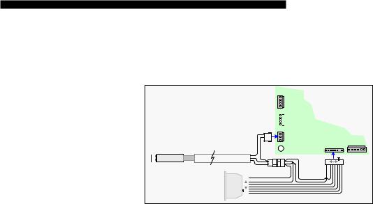
3.After properly connecting the ESD Wrist Strap to the unit and securing it properly on the wrist. Disconnect the 3-position connector installed at header P10 of the TSC controller and disconnect the 8-position connector installed at header P14 of the TSC controller (reference Illustration below Existing Humidity control System). This harness will not be reconnected to the unit. To remove the harness use side cutter pliers, cut the cable ties to free the wiring of P14 from the balance of wiring in the left side of the front controls section. Use care to prevent damage to other wiring of the unit. Take note of harness, You will need to wire tie new harness in same fashion.
Attach strap to unit |
Existing Humidity Control System |
Proofer Light |
|
|
||
|
||
|
Wire Harness |
|
|
|
|
Existing RH |
|
|
|
Sensor |
|
6 |
|
3 |
Humidity |
|
|
4 |
|
||
1 |
PCB |
5 |
3 |
2 |
|||
2 |
|
3 |
|
|
|
1 |
2 |
|
|
|
1 |
|
Located under rear |
|
Remove |
|
|
connector |
|
|
Proofer back cover |
|
|
|
|
|
P8
RTD O
P9 TSC
RTD P Controller
PCB
P10
RH P P14 USB Com
2
TSC HUMIDITY PROBE
REPLACEMENT INSTRUCTIONS
4.Remove the two screws retaining the access panel for the USB Module and circuit breaker on the left side of the TSC Oven. The P14 connects to the USB Module installed on the left side of the TSC oven. Disconnect the existing wire harness from the rear of the USB Module. Discard of the 512563 USB wire harness.
Installing Instructions for New 512019 harness:
P8
RTD O
Replacement Humidity Control System
Install RH |
|
P9 |
Sensor |
|
RTD P |
Output |
|
|
3 |
P10 |
2 |
|
1 |
RH P |
Replacement
Humidity Sensor
2 |
1 |
1 |
2 |
RH Sensor Pwr
Existing USB |
USB |
1 |
Module |
Module |
|
(left side of unit) |
8 |
TSC
Controller
PCB
P14 |
|
P7 |
|
|
Door Sw |
||
USB Com |
|||
|
|||
1 |
8 |
|
|
5.After properly connecting the ESD Wrist Strap to the unit and securing it properly on the wrist. Plug in the new 512019 Wire Harness to P14 of the TSC controller with the 2-postion inline connector end of 512019 Wire Harness nearest P14. (reference Illustration above). Connector can only go on one way.
6.Route harness to the USB panel that was removed earlier. Connect the other end of the 512019 harness to the rear of the USB module.
7.Reinstall the left side USB access panel and cable tie the new 512019 Wire Harness to the control section wiring between the USB Module and the TSC controller similar to the original wire routing. NO WIRES ARE TO TOUCH
THE TRANSFORMER.
8.Ensure you have adequate slack in the harness to slide access panel to fully open position.
Preparing the interior proofer unit for the Installation of the new sensor:
9.Remove wire racks, False bottom panel, & right side plenum duct assembly by removing screws on both sides, front and rear, and at top of air duct if installed.
3
 Loading...