


Service Manual
BAKING CENTER
PROOFER OVEN WITH
TOUCH SCREEN
CONTROLS (TSC)
MODELS
TSC-6/18
Please read this manual completely before attempting to install, operate or service this equipment.
This document is prepared for trained Duke service technicians. It is not to be used by anyone not properly qualified to perform these procedures.
This Service Manual is not all encompassing. If you have not been trained on servicing this product, be sure to read the manual completely before attempting servicing. Be sure all necessary tools, test equipment, and skills are available. Those procedures for which you do not have the proper skills and test equipment must be performed only by a qualified Duke trained service technician.
This manual is Copyright © 2010 Duke Manufacturing Co. All rights reserved. Reproduction without written permission is prohibited. Duke is a registered
trademark of the Duke Manufacturing Co.
Duke Manufacturing Co.
2305 N. Broadway
St. Louis, MO 63102
Phone: 314-231-1130
Toll Free: 1-800-735-3853
Fax: 314-231-5074 www.dukemfg.com
P/N 512452B
Service Manual for Proofer Oven with Touch Screen Controls (TSC)
IMPORTANT WARNING AND SAFETY INFORMATION
THIS MANUAL HAS BEEN PREPARED FOR PERSONNEL QUALIFIED TO INSTALL ELECTRICAL EQUIPMENT, WHO SHOULD PERFORM THE INITIAL FIELD STARTUP AND ADJUSTMENTS OF THE EQUIPMENT COVERED BY THIS MANUAL.
READ THIS MANUAL THOROUGHLY BEFORE OPERATING, INSTALLING OR PERFORMING
MAINTENANCE ON THE EQUIPMENT.


 FAILURE TO FOLLOW ALL THE INSTRUCTIONS IN THIS MANUAL CAN CAUSE PROPERTY DAMAGE, INJURY OR DEATH.


 IMPROPER INSTALLATION, ADJUSTMENT, ALTERATION, SERVICE OR MAINTENANCE CAN CAUSE PROPERTY DAMAGE, INJURY OR DEATH.


 ELECTRICAL CONNECTIONS SHOULD BE PERFORMED ONLY BY A CERTIFIED PROFESSIONAL.


 ELECTRICAL AND GROUNDING CONNECTIONS MUST COMPLY WITH THE APPLICABLE PORTIONS OF THE NATIONAL ELECTRIC CODE AND/OR ALL LOCAL ELECTRIC CODES. FAILURE TO COMPLY WITH THIS PROCEDURE CAN CAUSE PROPERTY DAMAGE, INJURY OR DEATH.


 BEFORE CONNECTING THE UNIT TO THE ELECTRICAL SUPPLY, VERIFY THAT THE ELECTRICAL AND GROUNDING CONNECTIONS COMPLY WITH THE APPLICABLE PORTIONS OF THE NATIONAL ELECTRIC CODE AND/OR OTHER LOCAL ELECTRICAL CODES. FAILURE TO COMPLY WITH THIS PROCEDURE CAN CAUSE PROPERTY DAMAGE, INJURY OR DEATH.


 BEFORE CONNECTING THE UNIT TO THE ELECTRICAL SUPPLY, VERIFY THAT THE ELECTRICAL CONNECTION AGREES WITH THE SPECIFICATIONS ON THE DATA PLATE. FAILURE TO COMPLY WITH THIS PROCEDURE CAN CAUSE PROPERTY DAMAGE, INJURY OR DEATH.


 UL73 GROUNDING INSTRUCTIONS: THIS APPLIANCE MUST BE CONNECTED TO A GROUNDED, METAL, PERMANENT WIRING SYSTEM. OR AN EQUIPMENT-GROUNDING CONDUCTOR MUST BE RUN WITH THE CIRCUIT CONDUCTORS AND CONNECTED TO THE EQUIPMENTGROUNDING TERMINAL OR LEAD ON THE APPLIANCE. FAILURE TO COMPLY WITH THIS PROCEDURE CAN CAUSE PROPERTY DAMAGE, INJURY OR DEATH.


 APPLIANCES EQUIPPED WITH A FLEXIBLE ELECTRIC SUPPLY CORD, ARE PROVIDED WITH A THREE-PRONG GROUNDING PLUG. IT IS IMPERATIVE THAT THIS PLUG BE CONNECTED INTO A PROPERLY GROUNDED THREE-PRONG RECEPTACLE. FAILURE TO COMPLY WITH THIS PROCEDURE CAN CAUSE PROPERTY DAMAGE, INJURY OR DEATH.


 IF THE RECEPTACLE IS NOT THE PROPER GROUNDING TYPE, CONTACT AN ELECTRICIAN. DO NOT REMOVE THE GROUNDING PRONG FROM THE PLUG. FAILURE TO COMPLY WITH THIS PROCEDURE CAN CAUSE PROPERTY DAMAGE, INJURY OR DEATH.
2

Service Manual for Proofer Oven with Touch Screen Controls (TSC)


 BEFORE PERFORMING ANY SERVICE THAT INVOLVES ELECTRICAL CONNECTION OR DISCONNECTION AND/OR EXPOSURE TO ELECTRICAL COMPONENTS, ALWAYS PERFORM THE ELECTRICAL LOCKOUT/TAGOUT PROCEDURE. DISCONNECT ALL CIRCUITS. FAILURE TO COMPLY WITH THIS PROCEDURE CAN CAUSE PROPERTY DAMAGE, INJURY OR DEATH.


 BEFORE REMOVING ANY SHEET METAL PANELS OR SERVICING THIS EQUIPMENT, ALWAYS PERFORM THE ELECTRICAL LOCKOUT/TAGOUT PROCEDURE. BE SURE ALL CIRCUITS ARE DISCONNECTED. FAILURE TO COMPLY WITH THIS PROCEDURE CAN CAUSE PROPERTY DAMAGE, INJURY OR DEATH.
 DO NOT OPERATE THIS EQUIPMENT WITHOUT PROPERLY PLACING AND SECURING ALL COVERS AND ACCESS PANELS. FAILURE TO COMPLY WITH THIS PROCEDURE CAN CAUSE PROPERTY DAMAGE, INJURY OR DEATH.


 DO NOT USE OR STORE GASOLINE OR OTHER FLAMMABLE VAPORS OR LIQUIDS IN THE VICINITY OF THIS OR ANY OTHER APPLIANCE. FAILURE TO COMPLY CAN CAUSE PROPERTY DAMAGE, INJURY OR DEATH.


 IN THE EVENT OF A POWER FAILURE, DO NOT ATTEMPT TO OPERATE THIS APPLIANCE. FAILURE TO COMPLY CAN CAUSE PROPERTY DAMAGE, INJURY OR DEATH.
3

Service Manual for Proofer Oven with Touch Screen Controls (TSC) |
|
TABLE OF CONTENTS |
|
INTRODUCTION.................................................................................................................................................................................................... |
5 |
INSTALLATION............................................................................................................................................................................................. |
5 |
OPERATION................................................................................................................................................................................................... |
5 |
CLEANING..................................................................................................................................................................................................... |
5 |
SEQUENCE OF OPERATION....................................................................................................................................................................... |
5 |
TOOLS ........................................................................................................................................................................................................... |
5 |
SPECIFICATIONS.......................................................................................................................................................................................... |
5 |
REMOVALAND REPLACEMENT OF COMPONENTS..................................................................................................................................... |
7 |
ELECTRICAL LOCKOUT/TAGOUT PROCEDURE................................................................................................................................... |
7 |
COVERS AND PANELS................................................................................................................................................................................ |
7 |
Proofer Rear Panel.................................................................................................................................................................................. |
7 |
Oven Rear Panels................................................................................................................................................................................... |
8 |
Oven Fan Cage and Wire Harness Cover............................................................................................................................................... |
9 |
Proofer Floor Panel................................................................................................................................................................................. |
9 |
Oven Ceiling Panel............................................................................................................................................................................... |
10 |
Electrical Compartment Access Panel.................................................................................................................................................. |
10 |
AC Power Access Panel....................................................................................................................................................................... |
11 |
AC INPUT VOLTAGE WIRING CONNECTIONS..................................................................................................................................... |
11 |
Electrical Compartment Components................................................................................................................................................... |
12 |
Electrical Compartment Cooling Fan................................................................................................................................................... |
12 |
Hi Limit Breaker................................................................................................................................................................................... |
13 |
ON/OFF Circuit Breaker...................................................................................................................................................................... |
13 |
Touchpad Controller............................................................................................................................................................................. |
14 |
Oven Blower Relay.............................................................................................................................................................................. |
15 |
Proofer and Oven Light Transformers.................................................................................................................................................. |
16 |
Oven Element Contactor...................................................................................................................................................................... |
16 |
Oven Door Safety Switch..................................................................................................................................................................... |
17 |
Beeper................................................................................................................................................................................................... |
17 |
Proofer Lights Circuit Breaker............................................................................................................................................................. |
18 |
USB Port............................................................................................................................................................................................... |
18 |
Proofer and Oven Halogen Lamps....................................................................................................................................................... |
18 |
Proofer Heat Elements.......................................................................................................................................................................... |
19 |
Proofer Circulation Fan........................................................................................................................................................................ |
20 |
Water Injection Solenoid...................................................................................................................................................................... |
21 |
Humidity Sensor................................................................................................................................................................................... |
22 |
Humidity PC Board.............................................................................................................................................................................. |
23 |
OPTIMIST NOZZLE.................................................................................................................................................................................... |
23 |
OVEN HEAT ELEMENTS........................................................................................................................................................................... |
24 |
OVEN BLOWER MOTOR........................................................................................................................................................................... |
25 |
OVEN BLOWER MOTOR START CAPACITOR....................................................................................................................................... |
26 |
OVEN HIGH LIMIT THERMOSTAT.......................................................................................................................................................... |
27 |
DOOR GASKET REPLACEMENT............................................................................................................................................................. |
27 |
ADJUSTMENTS.................................................................................................................................................................................................... |
28 |
DOOR GASKET COMPRESSION CHECK................................................................................................................................................ |
28 |
PROOFER DOOR GASKET ADJUSTMENT............................................................................................................................................. |
28 |
OVEN AIR WASH DOOR ADJUSTMENT................................................................................................................................................. |
29 |
TOUCH SCREEN DISPLAY BRIGHTNESS ADJUSTMENT................................................................................................................... |
30 |
FIELD TEMPERATURE CALIBRATION PROCEDURE.......................................................................................................................... |
31 |
MAINTENANCE................................................................................................................................................................................................... |
32 |
STAINLESS STEEL CARE.......................................................................................................................................................................... |
32 |
WATER FILTER REPLACEMENT.............................................................................................................................................................. |
32 |
CLEANING THE OPTIMIST NOZZLE...................................................................................................................................................... |
34 |
TROUBLESHOOTING......................................................................................................................................................................................... |
35 |
ELECTRICAL SCHEMATIC................................................................................................................................................................................ |
37 |
TSC OVEN LINE SUPPLY WIRING................................................................................................................................................................... |
38 |
CUSTOMER ASSISTANCE.................................................................................................................................................................................. |
39 |
4

Service Manual for Proofer Oven with Touch Screen Controls (TSC)
INTRODUCTION
INSTALLATION
For detailed installation instructions, refer to the Owner’s Manual (512792).
OPERATION
For specific operating instructions, refer to the Owner’s Manual (512792).
CLEANING
For specific instructions, refer to the Owner’s Manual (512792).
SEQUENCE OF OPERATION
For specific instructions, refer to the Owner’s Manual (512792).
TOOLS
STANDARD
•Standard set of hand tools.
•Insulated Trim Pot Screwdriver
•VOM with AC current tester. (Any quality VOM or DVM with a sensitivity of at least 20,000 Ohms per Volt can be used.)
•A ladder or other appropriate item to stand on, if servicing the top of the unit.
SPECIFICATIONS
US and Foreign Patents Pending TSC Model
Shipping Weight: Carton Box: 637 lbs / 288 kg
Shipping Weight: Wooden Crate: 772 lbs / 350 kg
Electrical Specifications
AC VOLTAGE |
HZ |
PHASE |
|
WATTS |
AMPERAGE |
|
208 |
60 |
1 |
|
6650 |
32 |
|
208 |
60 |
3P |
|
6650 |
32 |
1 |
240 |
50/60 |
1 |
|
7200 |
30 |
|
240 |
60 |
3P |
|
7200 |
30 |
1 |
380 – 415 |
50 |
3N |
|
7200 |
30 |
2 |
|
|
|
|
|||
1: L1<15A, L2<15A, L3<25A |
|
2: L1<15A, L2<15A, L3<15A, N=Common |
|
|||
Compliance Declaration
5

Service Manual for Proofer Oven with Touch Screen Controls (TSC)
Dimensions
6
Service Manual for Proofer Oven with Touch Screen Controls (TSC)
REMOVALAND REPLACEMENT OF COMPONENTS
ELECTRICAL LOCKOUT/TAGOUT
PROCEDURE
 WARNING
BEFORE PERFORMING ANY SERVICE THAT INVOLVES ELECTRICAL CONNECTION OR DISCONNECTION AND/OR EXPOSURE TO ELECTRICAL COMPONENTS, ALWAYS FOLLOW THE ELECTRICAL LOCKOUT/ TAGOUT PROCEDURE. DISCONNECT ALL CIRCUITS. FAILURE TO COMPLY CAN CAUSE PROPERTY DAMAGE, INJURY OR DEATH.
TheElectricalLOCKOUT/TAGOUTProcedureisused toprotectpersonnelworkingonanelectricalappliance. Before performing any maintenance or service that requires exposure to electrical components, follow these steps:
1.In electrical box, place appliance circuit breaker into OFF position.
2.Placealockorotherdeviceonelectricalboxcover to prevent someone from placing circuit breaker ON.
3.Place a tag on electrical box cover to indicate that appliance has been disconnected for service and power should not be restored until tag is removed by maintenance personnel.
4.Disconnect appliance power cord from electrical outlet.
COVERS AND PANELS
 WARNING
BEFORE PERFORMING ANY SERVICE THAT INVOLVES ELECTRICAL CONNECTION OR DISCONNECTION AND/OR EXPOSURE TO ELECTRICAL COMPONENTS, ALWAYS FOLLOW THE ELECTRICAL LOCKOUT/ TAGOUT PROCEDURE. DISCONNECT ALL CIRCUITS. FAILURE TO COMPLY CAN CAUSE PROPERTY DAMAGE, INJURY OR DEATH.
CAUTION: Interior components and surfaces may be hot if the unit has been in recent use.
General Service Note: During its installation, this unit is required it to be secured to the building structure. There is also a Restraining Device (a heavy, flexible metal cable) that was installed to prevent the unit from moving beyond a certain distance in order to prevent damage to the electrical conduit feeding it. Most service can be accomplished without moving the unit from its mounted position. However, if the unit is moved during service, then thesesecuringdevicesmustbereinstalledforcontinued protectionagainsttip-overandtomeetothercompliance regulations.
Proofer Rear Panel
5.Place a tag on the cord to indicate that unit has been disconnected for service and power should notberestoreduntiltagisremovedbymaintenance personnel.
 WARNING
BEFORE PERFORMING ANY SERVICE THAT INVOLVES ELECTRICAL CONNECTION OR DISCONNECTION AND/OR EXPOSURE TO ELECTRICAL COMPONENTS, ALWAYS FOLLOW THE ELECTRICAL LOCKOUT/ TAGOUT PROCEDURE. DISCONNECT ALL CIRCUITS. FAILURE TO COMPLY CAN CAUSE PROPERTY DAMAGE, INJURY OR DEATH.
7
Service Manual for Proofer Oven with Touch Screen Controls (TSC)
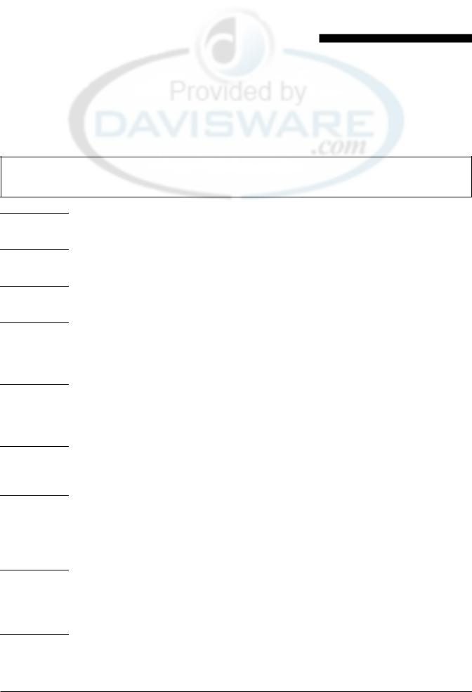
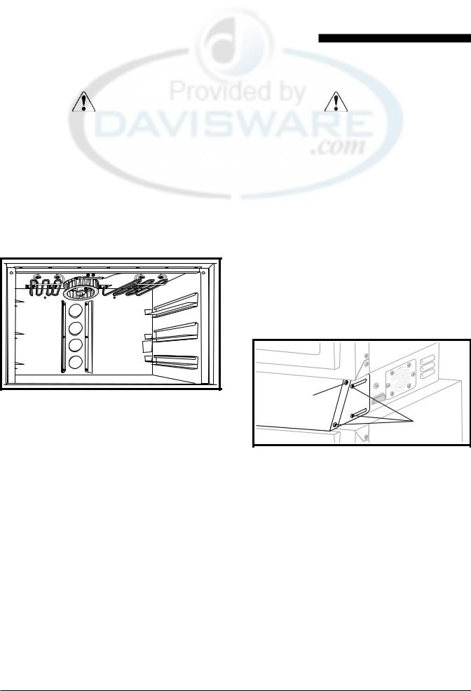
and Oven Light Fixture wiring harness. Right and Left Panels provide access to the Oven Burner Element connections and Element wiring harnesses.
Figure 1: Proofer – Rear Panel Removed
1.Place the unit’s Power Switch in its OFF position, andfollowtheproperLockout/Tagoutprocedures.
2.Remove all of the self-tapping sheet metal screws that secure the Rear Panel to the Proofer. Set aside for reuse.
3.Remove the Rear Panel to gain access to the components located at the rear of the Proofer.
Oven Rear Panels
 WARNING
BEFORE PERFORMING ANY SERVICE THAT INVOLVES ELECTRICAL CONNECTION OR DISCONNECTION AND/OR EXPOSURE TO ELECTRICAL COMPONENTS, ALWAYS FOLLOW THE ELECTRICAL LOCKOUT/ TAGOUT PROCEDURE. DISCONNECT ALL CIRCUITS. FAILURE TO COMPLY CAN CAUSE PROPERTY DAMAGE, INJURY OR DEATH.
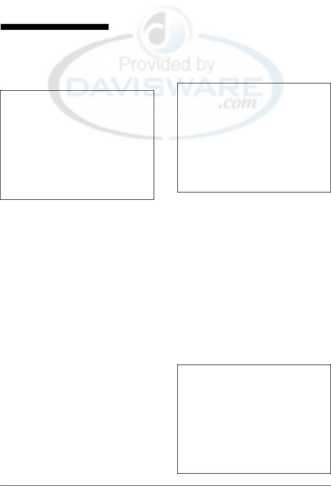
The oven section of the unit has three rear panels. The CenterPanelprovidesaccesstotheOvenLightFixtures
Figure 2: Oven – Right Side Panel Removed
1.Place the unit’s Power Switch in its OFF position, andfollowtheproperLockout/Tagoutprocedures.
2.Remove the screws securing the Center Panel. Retain for reuse.
3.Remove the Center Panel to gain access to Light Fixtures and wiring harness.
Note: The Center Panel side screws must be removed when removing either of the side panels.
4.RemovethescrewssecuringtheSidePanels.Retain for reuse.
5.Carefully remove the insulation to access to the OvenBurnerElementconnectionsandOvenBurner Element wiring harness. Retain the insulation for reuse.
8
Service Manual for Proofer Oven with Touch Screen Controls (TSC)
Oven Fan Cage and Wire Harness Cover |
|
Proofer Floor Panel |
|
|
|
WARNING |
|
WARNING |
BEFORE PERFORMING ANY SERVICE THAT |
|
BEFORE PERFORMING ANY SERVICE THAT |
INVOLVES ELECTRICAL CONNECTION |
|
INVOLVES ELECTRICAL CONNECTION |
OR DISCONNECTION AND/OR EXPOSURE |
|
OR DISCONNECTION AND/OR EXPOSURE |
TO ELECTRICAL COMPONENTS, ALWAYS |
|
TO ELECTRICAL COMPONENTS, ALWAYS |
FOLLOW THE ELECTRICAL LOCKOUT/ |
|
FOLLOW THE ELECTRICAL LOCKOUT/ |
TAGOUT PROCEDURE. DISCONNECT ALL |
|
TAGOUT PROCEDURE. DISCONNECT ALL |
CIRCUITS. FAILURE TO COMPLY CAN |
|
CIRCUITS. FAILURE TO COMPLY CAN |
CAUSE PROPERTY DAMAGE, INJURY OR |
|
CAUSE PROPERTY DAMAGE, INJURY OR |
DEATH. |
|
DEATH. |
|
|
|
Figure 3: Oven Fan Cage and
Wire Harness Cover
1.Place the unit’s Power Switch in its OFF position, andfollowtheproperLockout/Tagoutprocedures.
2.Remove the four screws securing the Oven Fan Cage to top of the unit. Retain for reuse.
3.Remove the cage to gain access to the Oven Fan Motor.
4.Remove the screws securing the Oven Fan Wire Harness Cover to the top of the unit. Retain for reuse.
5.RemovetheOvenFanWireHarnessCovertogain access to the wiring harness and connections.
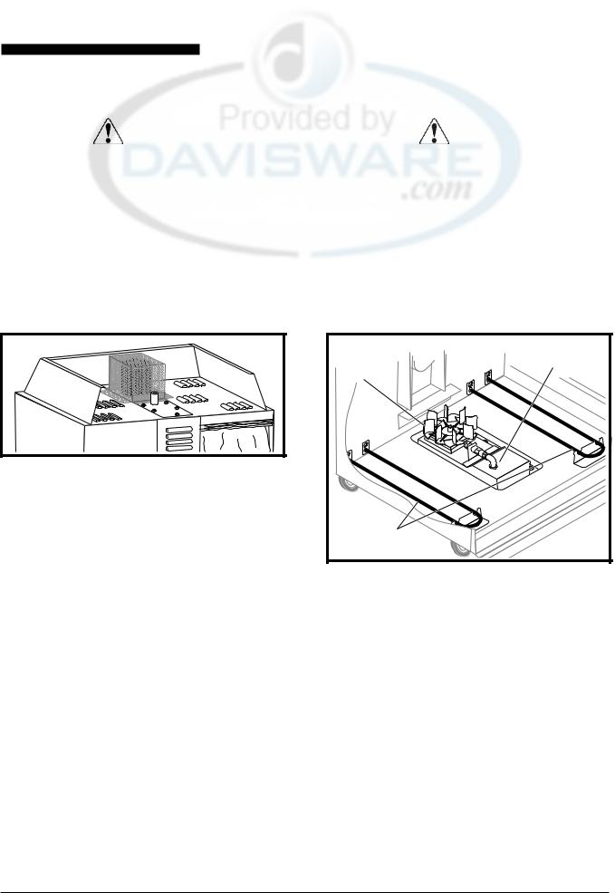
Proofer |
Optimist |
Circulating |
Assembly |
Fan |
|
Heat |
|
Elements |
|
Figure 4: View of Proofer Components
with Floor Panel Removed
1.Place the unit’s Power Switch in its OFF position, andfollowtheproperLockout/Tagoutprocedures.
2.Remove the screws securing the Proofer Floor Panel.
3.Slide the panel out through the front of the unit being careful not to damage the fan blades or optimist nozzle.
Access to the Proofer Heater Elements, Opti Mist Assembly, Proofer Circulating Fan is available with the Proofer Floor Panel removed.
9
Service Manual for Proofer Oven with Touch Screen Controls (TSC)
Oven Ceiling Panel |
|
Electrical Compartment Access Panel |
|
|
|
WARNING |
|
WARNING |
BEFORE PERFORMING ANY SERVICE THAT |
|
BEFORE PERFORMING ANY SERVICE THAT |
INVOLVES ELECTRICAL CONNECTION |
|
INVOLVES ELECTRICAL CONNECTION |
OR DISCONNECTION AND/OR EXPOSURE |
|
OR DISCONNECTION AND/OR EXPOSURE |
TO ELECTRICAL COMPONENTS, ALWAYS |
|
TO ELECTRICAL COMPONENTS, ALWAYS |
FOLLOW THE ELECTRICAL LOCKOUT/ |
|
FOLLOW THE ELECTRICAL LOCKOUT/ |
TAGOUT PROCEDURE. DISCONNECT ALL |
|
TAGOUT PROCEDURE. DISCONNECT ALL |
CIRCUITS. FAILURE TO COMPLY CAN |
|
CIRCUITS. FAILURE TO COMPLY CAN |
CAUSE PROPERTY DAMAGE, INJURY OR |
|
CAUSE PROPERTY DAMAGE, INJURY OR |
DEATH. |
|
DEATH. |
|
|
|
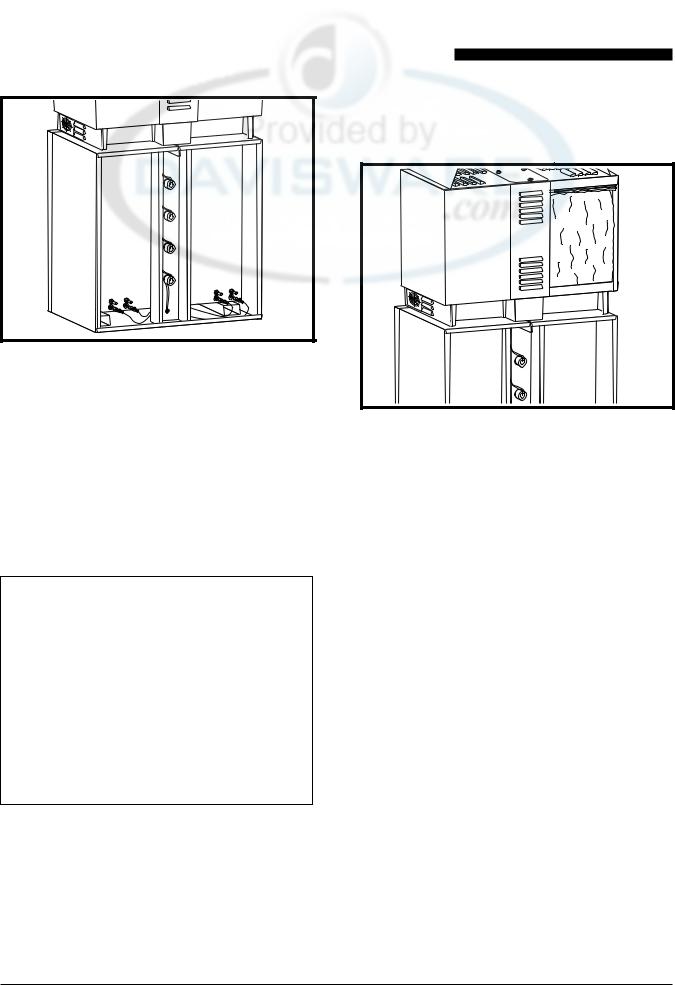
Figure 5: View of Oven Components
with Ceiling Panel Removed
1.Place the unit’s Power Switch in its OFF position, andfollowtheproperLockout/Tagoutprocedures.
2.Remove the Oven Racks
3.Remove the screws securing the panel. Retain screws for reuse.
4.It may be necessary to pry the panel forward from the front of the unit. Be careful not to damage the fan blade when removing the panel.
Access to Oven Heating Elements, Fan Blade, Oven RTD and Hi Limit Thermostat, is available with the Oven Ceiling Panel removed.
It is not necessary to move the unit to gain access to the Electrical Component Compartment. It might become necessary to remove the unit from the wall if troubleshooting leads into other areas. Refer to the specific component section of this manual when replacing a component in the Electrical Compartment.
Remove |
Loosen |
Figure 6: Electrical Compartment
Access Panel Screw Locations
1.Place the unit’s Power ON/OFF Switch in its OFF position and follow the proper Lockout/Tagout procedures.
2.Refer to the drawing and loosen the appropriate screws.
3.Also, referring to the drawing remove the two screws at the top of the Control Access Panel.
4.Pull the panel forward then pivot it downward.
10
Service Manual for Proofer Oven with Touch Screen Controls (TSC)
CAUTION: DO NOT power on the unit while the Control Panel is in the open position.
5.To troubleshoot for problems, use visual checks, anOhmmeter,theproperSchematicfortheversion of the unit being serviced.
|
Oven |
Oven |
Transformers |
Blower |
Element |
|
Relay |
Contactor |
Control |
Touch Pad |
|
Access Panel |
Controller |
|
The AC Power Access Panel is located at the rear of the unit. It may be necessary to move the unit to gain access to this area.This unit makes use of a restraining devicetoprotectthepowercableandwatersupplyline.
L2 |
L3 |
N |
Figure 8: AC Access and Connect Block
with Cover Removed
Figure 7: Electrical Compartment Components
CAUTION: When closing the Control Panel, make sure that wires do not become pinched between the Control Panel and the cabinet surfaces.
6.Reverse steps 2 through 4 to secure the Control Access Panel.
AC Power Access Panel
 WARNING
BEFORE PERFORMING ANY SERVICE THAT INVOLVES ELECTRICAL CONNECTION OR DISCONNECTION AND/OR EXPOSURE TO ELECTRICAL COMPONENTS, ALWAYS FOLLOW THE ELECTRICAL LOCKOUT/ TAGOUT PROCEDURE. DISCONNECT ALL CIRCUITS. FAILURE TO COMPLY CAN CAUSE PROPERTY DAMAGE, INJURY OR DEATH.
1.Place the unit’s Power ON/OFF Switch in its OFF position, and follow the proper Lockout/Tagout procedures.
2.Remove the three screws securing the panel to the unittogainaccesstotheACPowerConnectBlock.
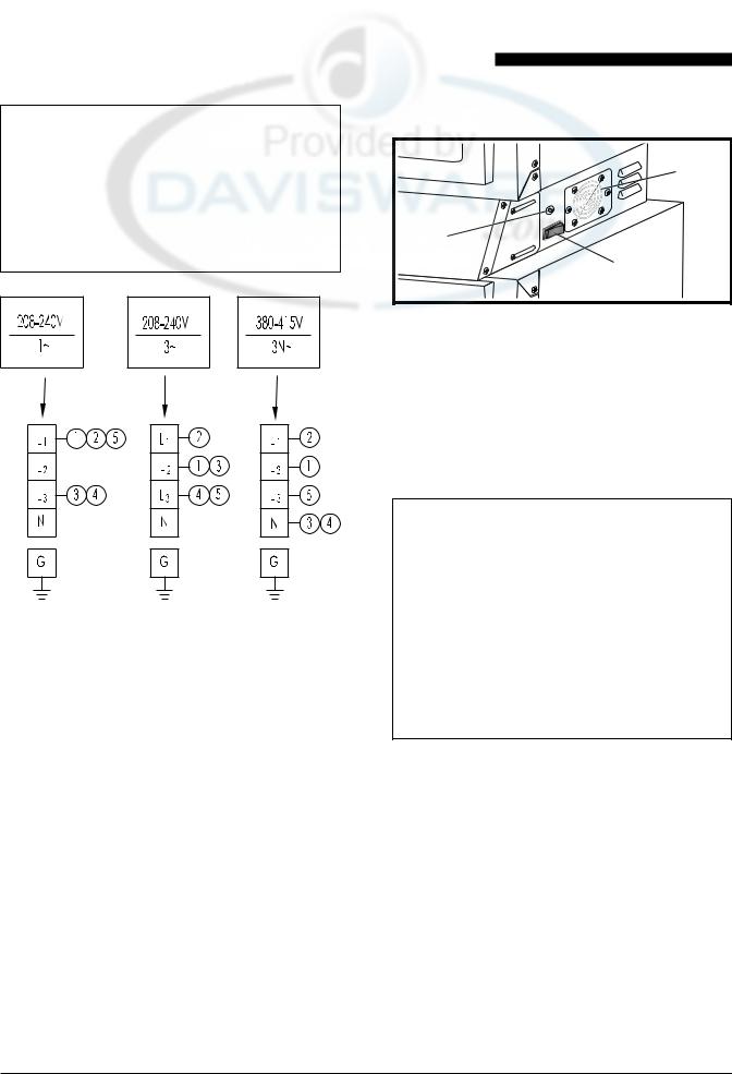
AC INPUT VOLTAGE WIRING CONNECTIONS
 WARNING
BEFORE PERFORMING ANY SERVICE THAT INVOLVES ELECTRICAL CONNECTION OR DISCONNECTION AND/OR EXPOSURE TO ELECTRICAL COMPONENTS, ALWAYS FOLLOW THE ELECTRICAL LOCKOUT/ TAGOUT PROCEDURE. DISCONNECT ALL CIRCUITS. FAILURE TO COMPLY CAN CAUSE PROPERTY DAMAGE, INJURY OR DEATH.
11
Service Manual for Proofer Oven with Touch Screen Controls (TSC)
 WARNING
IF ALUMINUM AC SUPPLY WIRE IS PRESENT, THE UNIT IS NOT PROPERLY WIRED AND MUST BE TAKEN OUT OF SERVICE UNTIL IT IS PROPERLY REWIRED USING COPPER WIRE.
Figure 9: Possible Wiring Block Configurations
Note: Also refer to the TSC OVEN LINE SUPPLY WIRING diagrams at the back of this manual.
1.Place the unit’s Power ON/OFF Switch in its OFF position, and follow the proper Lockout/Tagout procedures.
2.Remove the AC Connect Block Cover Plate.
3.UseaVoltmetertocheckforthepresenceofvoltage.
4.WithAC power removed and proper Lockout and Tagoutproceduresapplied,ensurethatthecontacts on the connect block are properly tightened.
Electrical Compartment Components
A |
C |
B |
Figure 10: Cooling Fan, Power On/Off
Switch and Hi Limit Thermostat
A:Cooling Fan
B:Power ON/OFF Switch
C:Hi Limit Thermostat
Electrical Compartment Cooling Fan
 WARNING
BEFORE PERFORMING ANY SERVICE THAT INVOLVES ELECTRICAL CONNECTION OR DISCONNECTION AND/OR EXPOSURE TO ELECTRICAL COMPONENTS, ALWAYS FOLLOW THE ELECTRICAL LOCKOUT/ TAGOUT PROCEDURE. DISCONNECT ALL CIRCUITS. FAILURE TO COMPLY CAN CAUSE PROPERTY DAMAGE, INJURY OR DEATH.
This fan is mounted on the electrical compartment on the right side of the unit.
1.Place the unit’s Power ON/OFF Switch in its OFF position, and follow the proper Lockout/Tagout procedures.
2.Remove the two screws securing the Cooling Fan panel to the electrical compartment.
3.Tag and disconnect the cooling fan wires.
4.Removethefournutssecuringthefantothepanel. Retain the nuts for reuse.
5.Remove the fan.
6.Reverse this procedure to install the replacement fan.
12
 Loading...