


613-E1-E4

613 & E SERIES
ELECTRIC
CONVECTION OVEN
Installation and
Operation Manual
Please read this manual completely before attempting
to install, operate or service this equipment
This manual is Copyright © 2017 Duke Manufacturing Co. All rights reserved.
Reproduction without written permission is prohibited. Duke is a registered
trademark of the Duke Manufacturing Co.
Duke Manufacturing Co.
2305 N. Broadway
St. Louis, MO 63102
Phone: 314-231-1130
Toll Free: 1-800-735-3853
Fax: 314-231-5074
www.dukemfg.com
P/N: 152469
REV AC 12/07/2017

Installation and Operation of 613 & E Series Electric Convection Oven
2

Installation and Operation of 613 & E Series Electric Convection Oven
TABLE OF CONTENTS
IMPORTANT WARNING AND SAFETY INFORMATION ................................................................4
SPECIFICATIONS ........................................................................................................................... 4
INSTALLATION INSTRUCTIONS ...................................................................................................5
A. QUALIFIED PERSONNEL.................................................................................................5
B. DELIVERY AND INSPECTION ......................................................................................... 5
C. LOCATION OF THE OVEN ............................................................................................... 5
D. ELECTRICAL CONNECTIONS ........................................................................................5
E. OVEN ASSEMBLY .............................................................................................................6
Leg Attachment ................................................................................................................6
Caster Installation ............................................................................................................. 6
Double Sections ...............................................................................................................6
F. ADJUSTMENTS ASSOCIATED WITH INSTALLATION ..................................................6
OPERATING INSTRUCTIONS ........................................................................................................ 7
THE “E” & 6/13 SERIES OF CONVECTION OVENS ........................................................... 7
A. OVEN CONTROLS ............................................................................................................ 8
Electro-Mechanical ........................................................................................................... 8
“V” Controller Operating Instructions ................................................................................ 8
Cooking ..................................................................................................................... 9
“XX” Controller ............................................................................................................... 10
“XX” Controller Programming & Operating Instructions ..........................................10
“ZZ” Controller ................................................................................................................ 12
“ZZ” Controller Programming & Operating Instructions ...........................................12
“ZZ” Controller Repair Parts List .............................................................................16
B. GENERAL GUIDELINES FOR OPERATION .....................................................................17
Operation Instructions ....................................................................................................17
6/13 Electric Convection Ovens .....................................................................................17
C. Suggested Times & Temperatures ..................................................................................... 18
D. COOK & HOLD/ROAST & HOLD RECOMMENDED TIME & TEMPERATURE ...............19
COOK & HOLD - ROAST & HOLD ................................................................................19
E. General Guidelines for Cook & Hold - Roast & Hold ......................................................... 20
MAINTENANCE INSTRUCTIONS ................................................................................................ 20
A. ADJUSTMENTS ............................................................................................................... 20
B. DOOR ADJUSTMENT ..................................................................................................... 20
C. DOOR SWITCH ADJUSTMENT ..................................................................................... 21
D. THERMOSTAT CALIBRATION .......................................................................................21
Electro-Mechanical Controls Only (“Q” & “V”). Not applicable to Ovens
with Solid State Controls ................................................................................................21
To Check Calibration: .....................................................................................................21
To Calibrate the Ovens ...................................................................................................22
E. CLEANING OF THE OVENS ..........................................................................................22
6/13 – ELECTRIC CONVECTION OVEN REPAIR PARTS LIST ......................................23
MOUNTING FLUE EXTENSION TO TOP OVEN .................................................................. 24
SECURING DOUBLE STACKED OVENS .............................................................................24
6/13 DOOR ASSEMBLY (TYPICAL) .................................................................................... 25
6/13 “V” CONTROLLER ASSEMBLY ...................................................................................26
6/13 “XX” CONTROLLER ASSEMBLY ................................................................................ 27
6/13 CONTACTOR IDENTIFICATION ................................................................................. 28
“V” CONTROLLER WIRING SCHEMATIC .........................................................................29
“XX” ELECTRIC CONTROL WIRING SCHEMATIC........................................................... 30
“ZZ” CONTROLLER WIRING SCHEMATIC .......................................................................31
CUSTOMER ASSISTANCE ........................................................................................................32
3

Installation and Operation of 613 & E Series Electric Convection Oven
IMPORTANT WARNING AND SAFETY INFORMATION
FOR YOUR SAFETY:
Do not store or use gasoline or other ammable vapors or liquids
in the vicinity of this or any other appliance.
: Improper installation, adjustment, alteration, service or
maintenance can cause property damage, injury or death. Read the
installation, operating and maintenance instructions thoroughly before
installing or servicing this equipment.
THIS MANUAL MUST BE RETAINED FOR FUTURE REFERENCE.
SPECIFICATIONS
TOTAL KW VOLTAGE 1 PHASE 3 PHASE
10 KW 208 53 31
10 KW 240 46 27
10 KW 220/380 20
10 KW 240/415 18
10 KW 480 14
4

Installation and Operation of 613 & E Series Electric Convection Oven
INSTALLATION INSTRUCTIONS
A. QUALIFIED PERSONNEL
These installation instructions are for the use of qualied
installation and service personnel only. Installation or
service by other than qualied personnel may result in
damage to the oven and/or injury to the operator.
Qualied installation personnel are those individuals,
rms, companies or corporations which either in person or
through an agent is engaged in and responsible for:
• The installation of electrical wiring from the electric
meter, main control box or service outlet to the
electrical appliance. Qualied installation personnel
must be familiar with all precautions required and
have complied with all requirements of state and
local authorities having jurisdiction. See: National
Electrical Code, ANSI/NFPA70.
B. DELIVERY AND INSPECTION
Duke Manufacturing Co. does everything within its power
to insure you received your oven in good condition.
They are strapped down on heavy wooden skids and
surrounded by heavy “tri-wall” cartons to prevent shipping
damage. They have all been carefully inspected before
they were packaged and consigned to the carrier.
Upon delivery of your Duke oven:
• Look over the shipping container, carefully noting any
exterior damage on the delivery receipt, which must
also be signed by the driver/ delivery person.
• Uncrate and check for any damage, which was not
evident on the outside of the shipping container.
This is called concealed damage. The carrier must
be notied within fteen (15) days of the delivery
of the oven and the carton, skid and all packaging
materials must be retained for inspection.
Duke Manufacturing Co. cannot assume liability for
loss or damage suffered in transit. The carrier assumes
full responsibility for delivery in good order when the
shipment was accepted. However, we are prepared to
assist you in ling your claim.
C. LOCATION OF THE OVEN
Proper planning and placement of the oven will give you
the best results in terms of long-term user convenience
and satisfactory performance. We urge you to give
adequate thought in the placement of your oven prior
to its arrival.
• The oven should be placed in an area that is free
from drafts and accessible for proper operation
and servicing.
• Refer to the Oven Placement Clearances Chart
before installing the oven.
OVEN PLACEMENT CLEARANCES CHART
COMBUSTIBLE NON-COMBUSTIBLE
Right Side 1" 0"
Left Side 1" 0"
Rear 3" 3"
Floor 8" 8"
It is also important not to obstruct the natural ow of
ventilation air if the oven is to operate properly. This
oven should not be installed on a curb base or sealed
to the wall. Either condition can restrict the ow of air to
or prevent proper ventilation of the blower motor. The
blower motor has a thermal protection device, which will
trip, because of excessive ambient temperatures at the
back of the oven. This condition should be corrected
immediately to avoid damaging the oven permanently.
Before making any connections to the oven, check the
specication plate to be sure the oven specications
concur with the voltage and phase to be supplied to
the oven.
The specication plate is located behind the lower front
panel. To access the specication plate, loosen the four
screws below the doors, and pull the panel outward.
The specication plate bearing the oven’s serial number
is attached to the underside of the upper ledge above
the control panel.
D. ELECTRICAL CONNECTIONS
The oven is supplied for connection to a 208, 240, 440
or 480 volt grounded circuit. The electric motor, oven
lights, indicator lights and control circuits are connected
internally and require no secondary power supply.
Before making any connections to these units, check
the specication plate to assure that the voltage and
phase of the oven is compatible with the electrical
supply. When installing, all ovens must be electrically
grounded in accordance with local codes or in the
absence of local codes, with the National Electrical
Code, ANSI/NFPA 70 (in Canada – CSA Std. C22.1).
Wiring diagrams are located in the control compartment
5
Installation and Operation of 613 & E Series Electric Convection Oven
area. Standard wiring schematics are also included at
the back of this manual.
Note to Electrical Inspector: Inspection of
electrical connection should be accomplished by the
removal of the lower nishing piece. This is done by
loosening the four screws located in the door opening
under the doors.
E. OVEN ASSEMBLY
Before assembling and installing the oven, please
check to make sure that all necessary parts are
present. In addition to the oven itself, there will also
be four legs, four feet or four casters, the vent guard,
(for double sections: retaining clips & vent riser) and
miscellaneous hardware. Please check the interior of
all oven sections for the parts needed to assemble and
install the oven(s).
Leg Attachment
• Once the oven has been removed from the
carton, lay it on its left side (the side without the
controls).
• Hold the leg and align with the threaded hole in the
front corner of the bottom of the oven. Carefully start
the bolt in the corner (avoid cross threading).
NOTE: If you plan to use casters, a xed restraint of the
proper length must be incorporated to secure the oven to
a non-movable surface to eliminate strain on the power
cord. If the oven is removed from its normal position, the
restraint must then be reattached when returned.
Double Sections
• Secure the short legs to the bottom of the lower
section as described in previous section.
• Casters are installed by the method described for
single section ovens in the previous section.
• Place upper section on top of lower section and
align all edges of the ovens.
• Locate securing clips and align with holes on rear
frames of oven section, install three screws each
as provided and tighten.
• At the rear of the oven, install the ue connector
by sliding it up through the ue vent opening in
the top of the oven and over the upper ue vent.
Push it ush with the back of the oven then slide it
down over the lower ue vent. Attach with screws
provided.
• Install ue guard or draft hood adapter and draft
hood and draft hood collar to upper section.
• Align the other two leg plate holes in the leg with
those in the oven bottom and secure each leg using
the remaining two leg bolts. Repeat this process
for all legs.
• Raise the oven up on the legs.
• Level the oven by turning the adjustable feet in or
out as needed.
Caster Installation
• Casters are available as an option for both the
single and double oven sections.
• The installation of casters requires the removal of
the adjustable feet from the legs. This is done by
placing the bit of a large screwdriver against the lip
of the foot and rapping the screwdriver to drive the
foot out of the leg. The caster is then inserted fully
into the opening where the foot came out and the
locking nut tightened to expand the compression
sleeve of the caster.
NOTE: The casters with locking brakes are best mounted
on the front side of the oven for easier access.
F. ADJUSTMENTS ASSOCIATED WITH
INSTALLATION
Each oven section and all its component parts have
been tested thoroughly and inspected before the oven
was shipped from the factory. However, it is sometimes
necessary to further test or adjust the oven once it has
been installed. Such adjustments are the responsibility
of the Dealer or Installer. These types of adjustments
are not considered defects, rather a normal and routine
part of the proper installation of the equipment.
These adjustments include but are not limited to:
• Adjustments and recalibration of the thermostat
• Adjustment to the doors.
• Leveling.
• Tightening of fasteners.
No installation should be
considered complete without proper inspection
and, if necessary, any adjustments by qualied
service or installation personnel.
6
Installation and Operation of 613 & E Series Electric Convection Oven
OPERATING INSTRUCTIONS
The information in this section is intended for the use
of qualied operating personnel. Qualied Operating
Personnel are those individuals who have carefully
read the information contained in this manual, are
familiar with the function of the oven and/or have had
experience with operating the equipment described.
We recommend following these instructions to insure
optimum performance, long life and trouble-free service
from your oven.
THE “E” & 6/13 SERIES OF CONVECTION
OVENS
Convection cooking has been around from the 1960s. Its
advantages are well known. It differs from conventional
cooking by the movement of heated air within the
cooking cavity by means of a fan. This moving, heated
air helps to strip the cool air from around the product
being cooked, allowing the heat to penetrate more
rapidly. The results are that your product is cooked
quicker and at a lower temperature with the comparable
product quality found in conventional ovens.
Do not attempt to operate oven
during a power failure.
7
Installation and Operation of 613 & E Series Electric Convection Oven
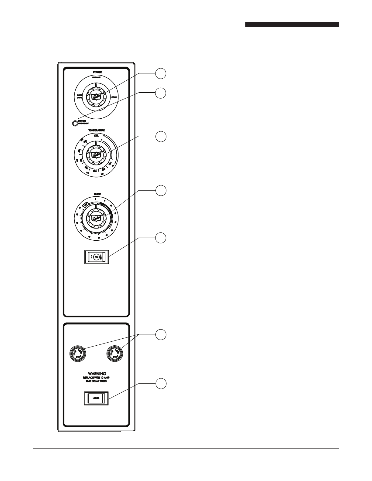
A. OVEN CONTROLS
1
"V" CONTROLLER
2
3
4
5
Electro-Mechanical
1. The Power Switch - Controls power to ON or Cool
Down Function.
2. The Indicator Light - When lit indicates burners
are operating. When the light goes out, the oven
has reached its cooking temperature.
3. The Cooking Thermostat - Controls the oven
temperature.
4. The Cooking Timer - Sounds an electric buzzer
on expiration of operator set time as a reminder
to remove product at end of cooking cycle.
NOTE: To set times of less than 25 minutes, turn timer
knob past 25 minutes and then back to the desired time.
5. The Fan Speed Switch (Optional) - Sets fan speed
to high or low.
6. The Fuse Holders - Contain circuit protecting
fuses.
7. The Light Switch - Controls interior lights.
“V” Controller Operating Instructions
Timer Resolution
The Timer displays time from 0 to 60 minutes, in one-
minute increments.
Temperature Scale
6
The Temperature Control displays the temperature in
°F. The temperature range is from 150°F - 500°F, in
25°F increments.
Cool Down
7
This feature enables the oven to be cooled rapidly by
allowing the fan to operate with the burners turned off.
To activate, turn the Power Switch to the COOL position
and open the oven door. When the door is opened
enough to disengage the door switch, the fan will turn
on. Closing the door will turn the fan off.
8

Installation and Operation of 613 & E Series Electric Convection Oven
Fan Speed Switch
The fan speed can be set to high or low speed by placing
the FAN HI/LOW button to the desired setting.
Cooking
A cooking cycle can be initiated as follows:
• Turn the Power Switch to COOK position.
• Set the Cooking Temperature by turning the
TEMPERATURE dial to the desired temperature.
The OVEN READY indicator light will turn on.
• When the OVEN READY indicator light turns off,
place the product to be cooked in the oven.
• Set the cooking Time by turning the COOK TIMER
dial to the desired time.
NOTE: To set times of less than 25 minutes, turn timer
knob past 25 minutes and then back to the desired time.
During the Cook Cycle, the OVEN READY Indicator
light will cycle on and off with the heating elements.
• When the COOK TIMER reaches “zero”, the alarm
will sound.
• To cancel the alarm, turn the COOK TIMER dial
to the OFF position.
9
Installation and Operation of 613 & E Series Electric Convection Oven
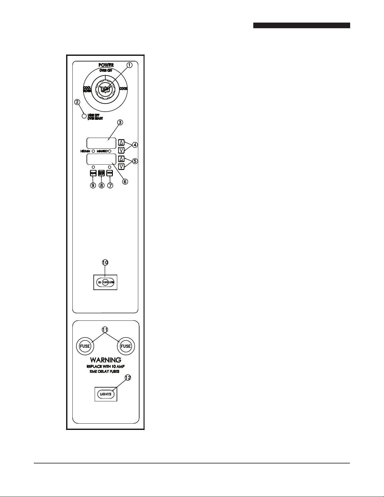
“XX” CONTROLLER
Oven Controls – Solid State Digital
1. The Power Switch – Controls power to Cook or
Cool Down functions.
2. The Indicator Light – When lit indicates burners
or elements are operating. When the light goes out,
the oven has reached the desired temperature.
3. The Time Digital Display – Displays time remaining
in the chosen cycle.
4. The Time Adjustment Buttons – Sets/Adjusts
countdown timer for cook cycle.
5. The Temperature Adjustment Buttons – Sets/
Adjusts cooking temperature.
6. The Temperature Digital Display – Displays the
temperature inside the oven
7. The Pulse Fan Button – Enables/Disables the
Pulse Fan Cycle.
8. The Start/Stop Button – Starts/Stops the cooking
cycle.
9. The Hold Button – Enable/Disables the Hold
Function.
10. The Fan Speed Switch (Optional) – Sets fan speed
to high or low.
11. The Fuse Holders – Each holds a 10 amp Time
Delay fuse.
12. The Light Switch – Turns interior lights on/off.
10
“XX” Controller
Programming & Operating Instructions
Models with the XX controller enable the oven to
cook food at a specied temperature for a specied
time period, than enter an optional hold mode. The
hold mode holds food at a specied temperature for a
specied period of time.
When the power switch is in the ON position the oven
will be in one of two modes:
• Cook Mode: In this mode the oven operates at a
specied temperature and the fan runs continuously,
unless the cycle option is selected. In cycle mode the
fan runs for 30 seconds and is off for 30 seconds. This
cycle continues during the specied cook time.
 Loading...