


Installation
Operation
& Maintenance
Manual
DUKE MANUFACTURING CO.
2305 N BROADWAY • ST. LOUIS, MO 63102 201351K 800.735.3853 • 314.231.1130 • 314.231.5074 Fax
www.dukemfg.com

Principles
Installation
Cord & Plug
Electrical
Operating
Care of Equipment |
7 |
A. Heating Elements |
7-9 |
B. Pilot Lights |
9 |
C. Hinge and Door Adjustments |
9-10 |
D. Damper Assembly |
11 |
E. Replacement of Pilots Lights or Thermostats |
11 |
Troubleshooting |
12 |
Recommended Food Storage Periods |
13 |
Parts List |
14-15 |
Unitrack Assembly |
16 |
Door Styles |
17 |
Angle Slides |
18-19 |
Number of Elements per Unit |
20 |
Please supply the ID Number and the Serial Number when ordering replacement parts or requesting service.
We recommend service by Duke Authorized Service Agencies during and after the warranty period.
2 of 20

The |
without the |
addition of |
heated and |
automatically |
depending |
upon its |
foods. |
The primary |
cooking unit |
until it is |
food, or for |
cooking. |
|
The Thermotainer, when it leaves the factory, is assembled and ready for Installation. The nameplate on the thermostat side of the cabinet contains model number, serial number, volts, hertz, wattage and instructions on the damper operation. The Thermotainer must be connected to the proper electrical power source as indicated on the nameplate. Failure to do this may cause serious damage, prevent proper operation and void the manufacturer's warranty.
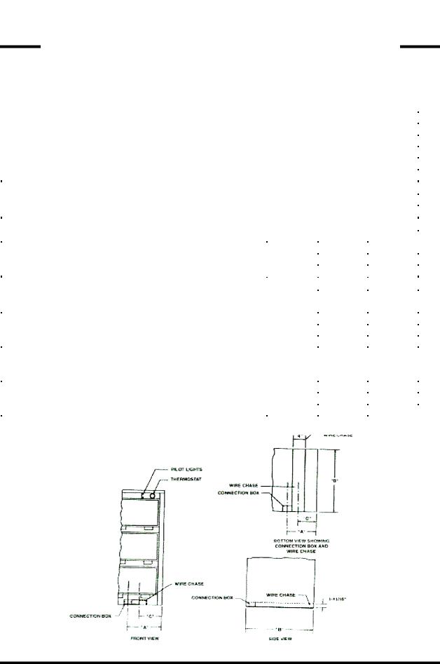
The access to the electrical connection box is normally located at the lower front (thermostat side) bottom. It is covered with an access cover panel that is held in place by two screws. Concealed, but adjacent to the right side of the electrical connection box is a wire chase that runs front to back. It is visible by looking underneath the unit. The wire chase permits access to the side knockout of the electrical connection box and to "stub up" or rear connects the electrical power source. Some Thermotainers may be equipped with cords and plugs or the electrical connection box may be in another location depending upon the design and location that may have been specified. It is not necessary to disassemble any part of the Thermotainer to make the electrical connection.
Thermotainers should be moved by carefully lifting underneath and placed in the desired location. They should not be pushed or shoved as this may damage the legs, the hardware, or the electrical components. After setting in place, the Thermotainer must be leveled. If equipped with legs, the adjusting feet should be turned to level the cabinet.
3 of 20

|
|
|
|
|
|
|
|
|
|
|
|
|
|
WATTAGE |
|
|
|
|
|
|
|
|
|
|
|
||
|
|
|
|
|
|
|
|
|
|
|
|
|
|
Up to |
|
|
|
|
|
|
|
|
|
|
|
|
|
1800 - |
|
|
|
|
|
|
|
|
|
|
|
|
|
1920 - |
|
|
|
|
|
|
|
|
|
|
|
|
|
2700 – 4500 |
|
1 |
|
37.5 |
|
8-3 |
|
5-50P |
|
5-50R |
|||
120 |
|
|
|
|
|||||||||
Up to |
3120 |
208 |
1 |
|
15.0 |
|
14-3 |
|
6-15P |
|
6-15R |
||
3120 – 3328 |
208 |
1 |
|
16.0 |
|
14-3 |
|
6-20P |
|
6-20R |
|||
3328 – 4680 |
208 |
1 |
|
22.5 |
|
12-3 |
|
6-30P |
|
6-30R |
|||
4680 – 7800 |
208 |
1 |
|
37.5 |
|
8-3 |
|
6-50P |
|
6-50R |
|||
Up to |
5757 |
208 |
3 |
|
16.0 |
|
12-4 |
|
15-20P |
|
15-20R |
||
5757 – 8096 |
208 |
3 |
|
22.5 |
|
10-4 |
|
15-30P |
|
15-30R |
|||
8096 – |
13493 |
208 |
3 |
|
37.5 |
|
6-4 |
|
15-50P |
|
15-50R |
||
Up to |
3600 |
240 |
1 |
|
15.0 |
|
14-3 |
|
6-15P |
|
6-15R |
||
3600 – 3840 |
240 |
1 |
|
16.0 |
|
14-3 |
|
6-20P |
|
6-20R |
|||
3840 – 5400 |
240 |
1 |
|
22.5 |
|
12-3 |
|
6-30P |
|
6-30R |
|||
5400 – 9000 |
240 |
1 |
|
37.5 |
|
8-3 |
|
6-50P |
|
6-50R |
|||
Up to |
6643 |
240 |
3 |
|
16.0 |
|
12-4 |
|
15-20P |
|
15-20R |
||
6643 – 9342 |
240 |
3 |
|
22.5 |
|
10-4 |
|
15-30P |
|
15-30R |
|||
9342 – |
15570 |
240 |
3 |
|
37.5 |
|
6-4 |
|
15-50P |
|
15-50R |
||
4 of 20
MODEL |
|
|
|
|
|
|
|
. |
1101-1101P |
|
|
|
|
|
|
|
|
|
|
|
|
|
|
|
|
|
1102-1102P |
|
|
|
|
|
|
|
|
|
|
|
|
|
|
|
|
|
1103-1103P |
|
|
|
|
|
|
|
|
|
|
|
|
|
|
|
|
|
1104-1104P |
|
|
|
|
|
|
|
|
|
|
|
|
|
|
|
|
|
1151-1151P |
|
|
|
|
|
|
|
|
|
|
|
|
|
|
|
|
|
1152-1152P |
|
|
|
|
|
|
|
|
|
|
|
|
|
|
|
|
|
1153-1153P |
|
|
|
|
|
|
|
|
1201-1201P |
|
|
|
|
|
|
|
|
|
|
|
|
|
|
|
|
|
1202-1202P |
|
|
|
|
|
|
|
|
|
|
|
|
|
|
|
|
|
1203-1203P |
|
|
|
|
|
|
|
|
|
|
|
|
|
|
|
|
|
1352-1352P |
|
|
|
|
|
|
|
|
|
|
|
|
|
|
|
|
|
1353-1353P |
|
|
|
|
|
|
|
|
|
|
|
|
|
|
|
||
1351-1351P |
|
|
|
|
|
|
|
|
2352-2352P |
|
|
|
21-1/2" |
27" |
17-1/2" |
|
|
2353-2353P |
|
|
|
|
|
|
|
|
1601-1601P |
1603-1603P |
|
|
13-1/2" |
27-1/2" |
9 1/2" |
|
|
1602-1602P |
|
|
|
|
|
|
|
|
1651-1651P |
2103-2103P |
2454-2454P |
2466-2466P |
|
|
|
|
|
1652-1652P |
2104-2104P |
2456-2456P |
2468-2468P |
|
|
|
|
|
1653-1653P |
2452-2452P |
2458-2458P |
2652-2652P |
18" |
32- |
14" |
|
|
2101-2101P |
2453-2453P |
2464-2464P |
2653-2653P |
|
|
|
|
|
2102-2102P |
|
|
|
|
|
|
|
|
1652A |
|
|
|
18" |
23-1/2" |
14" |
|
|
2201-2201P |
2302-2302P |
2308-2308P |
2318-2318P |
|
|
|
|
|
2202-2202P |
2303-2303P |
2309-2309P |
2602-2602P |
13-1/2" |
27- |
91/9" |
|
|
2203-2203P |
2304-2304P |
2314-2314P |
2603-2603P |
|
|
|
|
|
2204-2204P |
2306-2306P |
2316-2316P |
|
|
|
|
|
|
1253-1253P |
|
|
|
16" |
34" |
12" |
|
|
5 of 20

If legs were under the thermostat can be Installation local remain in must be Electric Sealant or approved
When the
the stainless steel angle slides inside the compartments. Clean and polish the inside and outside before preheating for the first time. This will assure the factory finish remaining bright for years. See Care of the Equipment section of this manual.
Electrical Control
The temperature is maintained by a thermostat (s) that can be adjusted to the desired temperature. The thermostat is directly connected to the heating elements, which in turn heat the air space surrounding each compartment. A thermostat may control one or more compartments depending upon the design.
Each Thermotainer is carefully inspected and tested at the factory. The thermostat (s) are adjusted and calibrated with precision temperature indicating instruments.
The thermostat dial temperature numbers may not necessarily indicate the exact compartment temperature. After it has been determined by use at which setting food keeps best, the thermostat should be kept at this setting to maintain this temperature. Your own experience will be the best guide. Do not constantly change the thermostat setting once it has been determined unless the foods being stored require different temperatures.
NOTE: Thermostats are factory calibrated. Field
calibration of the thermostat is not covered by
warranty. Preheating
bacteria cold knob least 1-
esired as this to be not
When the operating temperature has been reached, the red pilot light will go out. (It cycles on and off as the temperature varies in the compartment.) The Thermotainer is now ready to accept food for storage. If the food is to be served in the same pan in which it was cooked, it may be left in this pan and placed in the compartment. Otherwise pan food immediately after cooking into another utensil and place in the compartment. The Thermotainer keeps the food in perfect condition during the interval between cooking and serving.
All foods should be placed in the compartment while hot. The use of the Thermotainer for reheating or warming cold food is not recommended. If the Thermotainer is to be used for reheating food, consult a competent food or health authority for information concerning which foods may be cooled and reheated safely.
Most foods can be kept in their best condition at a temperature of approximately 175°F (79.4°C), but the exact temperature will vary with the kind of food and the method of preparation. Minor temperature fluctuations will not affect the quality of most foods. It is not possible to give exact instructions that will fit all conditions. It is suggested that you experiment by increasing or decreasing the temperature until you find the most suitable temperatures for various types of foods. For suggested temperature settings, consult the food storage instruction sheet on page 16.
6 of 20
 Loading...