


Service Manual
TACO BELL
DUAL-LINE
COUNTER
Please read this manual completely before attempting to install, operate or service this equipment
This document is prepared for trained Duke service technicians. It is not to be used by anyone not properly qualified to perform these procedures.
This Service Manual is not all encompassing. If you have not been trained on servicing this product, be sure to read the manual completely before attempting servicing. Be sure all necessary tools, test equipment, and skills are available. Those procedures for which you do not have the proper skills and test equipment must be performed only by a qualified Duke trained service technician.
This manual is copyright ©2011 Duke Manufacturing Company.All rights reserved. Reproduction without written permission is prohibited. Duke is a registered trademark of the Duke Manufacturing Company.
Duke Manufacturing Company
2305 N. Broadway • St. Louis, MO 63102 800.735.3853 • 314.231.1130
Fax: 314-231-5074 www.dukemfg.com
P/N 219209B
Service Manual for Taco Bell Dual-Line Counters
IMPORTANT WARNING AND SAFETY INFORMATION
WARNING
READ THIS MANUAL THOROUGHLY BEFORE OPERATING, INSTALLING, OR PERFORMING MAINTENANCE ON THE EQUIPMENT.
WARNING
FAILURE TO FOLLOW INSTRUCTIONS IN THIS MANUAL CAN CAUSE PROPERTY DAMAGE, INJURY OR DEATH.
WARNING
DO NOT STORE OR USE GASOLINE OR OTHER FLAMMABLE VAPORS OR LIQUIDS IN THE VICINITY OF THIS OR ANY OTHER APPLIANCE.
WARNING
DO NOT OPERATE THIS EQUIPMENT WITHOUT PROPERLY PLACING AND SECURING ALL COVER AND ACCESS PANELS.
CAUTION
Observe the following:
•Provide and maintain adequate minimum clearances from all walls and combustible materials.
•Provide and maintain adequate clearance for air openings.
•Keep the equipment area free and clear of combustible material.
•Operate equipment only on the type of electricity indicated on the specification plate.
•Retain this manual for future reference.
2

Service Manual for Taco Bell Dual-Line Counters |
|
TABLE OF CONTENTS |
|
TACO BELL DUAL-LINE COUNTER SPECIFICATIONS.................................................. |
4 |
INSTALLATION.................................................................................................................. |
4 |
Location........................................................................................................................ |
4 |
Leveling........................................................................................................................ |
4 |
Stabilizing..................................................................................................................... |
4 |
Electrical Connection................................................................................................... |
4 |
PARTS REMOVAL AND REPLACEMENT PROCEDURES............................................... |
5 |
DRY CHANNEL FOOD WARMERS............................................................................. |
5 |
Display Control Panel............................................................................................. |
5 |
Relay Box............................................................................................................... |
5 |
Dry Channel Power ON/OFF Switch...................................................................... |
5 |
Solid State Relay (SSR) ........................................................................................ |
6 |
Transformer ........................................................................................................... |
6 |
Channel Assembly.................................................................................................. |
6 |
TORTILLA GRILL AND TACO TOWER POWER ON/OFF SWITCHES....................... |
7 |
TRI-CHANNEL COLD PAN.......................................................................................... |
7 |
Evaporator.............................................................................................................. |
8 |
Tri-Channel Thermostat.......................................................................................... |
8 |
Tri-Channel Compressor Assembly........................................................................ |
8 |
REFRIGERATED BASE UNIT (RBC).......................................................................... |
9 |
Evaporator Fan Assembly...................................................................................... |
9 |
RBC Thermostat................................................................................................... |
10 |
RBC Refrigeration System................................................................................... |
11 |
RBC Door Gaskets............................................................................................... |
11 |
RBC Door Adjustment.......................................................................................... |
11 |
LOAD CENTER.......................................................................................................... |
12 |
Circuit Breaker Replacement..................................................................................... |
12 |
RECHARGING REFRIGERATION SYSTEM................................................................... |
13 |
TOOLS....................................................................................................................... |
13 |
Duke Service Bulletin Number 26 – Refrigeration System Evacuation...................... |
13 |
Duke Service Bulletin Number 35 – Accessing Sealed Refrigeration Systems......... |
13 |
SERVICE INFORMATION............................................................................................... |
14 |
MAINTENANCE......................................................................................................... |
14 |
Stainless Steel Care and Cleaning....................................................................... |
14 |
Compressor Air Filter Care................................................................................... |
14 |
TROUBLESHOOTING GUIDE......................................................................................... |
16 |
SCHEMATICS.................................................................................................................. |
18 |
3

Service Manual for Taco Bell Dual-Line Counters
TACO BELL DUAL-LINE COUNTER SPECIFICATIONS
MODEL |
DESCRIPTION |
VOLTAGE / WATTS |
DC-DLTB-M |
Counter, Dual-Line 157-1 |
120/208-240vac / 3798 |
INSTALLATION
LOCATION
The Dual-Line unit is intended for indoor use only. Be sure the chosen location has a floor strong enough to support the total weight of the unit fully loaded with food product. Reinforce the floor, if necessary, to provide for maximum loading. For the most efficient operation, be sure to provide good air circulation.
LEVELING
Be sure the unit is placed on a firm, flat surface/ floor. Check for cracks in flooring or tile and avoid theseareasifpossible.Ifnecessary,placesupport pads, properly rated for the weight of the unit, to “bridge”unevenorcrackedflooring.Leveltheunit accordingly using the leg adjusters.
STABILIZING
Use the leg adjustments to ensure that the unit is solid to the floor surface at all contact points. Ensurethattheunitdoesnot“rock”whenpressure is applied to the top corners.
ELECTRICAL CONNECTION
The Dual-Line unit requires Direct wiring Dual-Line unit to the power supply must be performed by a certified electrician and must comply with local electrical codes for your municipality.
 WARNING
REFER TO THE AMPERAGE DATA LIST IN THE SPECIFICATIONS
OR THE SERIAL TAG DATA AND YOUR LOCAL CODE OR THE NATIONAL ELECTRICAL CODE TO BE SURE UNIT IS CONNECTED TO THE PROPER POWER SOURCE.
A PROTECTED CIRCUIT OF THE CORRECT VOLTAGE AND AMPERAGE MUST BE RUN FOR CONNECTION OF THE SUPPLY CORD OR PERMANENT CONNECTION TO
THE UNIT. THE POWER MUST BE TURNED OFF AND DISCONNECTED WHENEVER PERFORMING MAINTENANCE OR REPAIR FUNCTIONS.
4

Service Manual for Taco Bell Dual-Line Counters
PARTS REMOVAL AND REPLACEMENT PROCEDURES
DRY CHANNEL FOOD WARMERS
Display Control Panel
The Dual-Line unit is equipped with two Dry Channel units, one on each side of the DualLine. Each Dry Channel unit has its own Display Control Panel.
Figure 1. Dry Channel Display
1.Place the Main Power ON/OFF switch in the OFF position.
2.Disconnect the Dual-Line unit from its power source.
3.Remove the four screws securing the Display ControlPanelandmoveDisplayControlPanel away from mounting surface.
4.IftheDisplayControlPanelistobecompletely removed, label and disconnect wires.
5.Remove Display Control Panel.
6.Reverse this procedure to install Display Control Panel.
Relay Box
Each Dry Channel unit is equipped with its own Relay Box. The Relay Box is located under the unit. Each Relay Box has an ON/OFF switch.
I |
Main Power |
On/Off Switch |
Figure 2. Relay Box Location
1.Place the Main Power ON/OFF Switch in the OFF position. Use proper Lockout/Tagout procedures.
2.Remove the four screws securing the Relay Box the bottom of the Dry Channel Unit.
3.If complete Relay Box is to be replaced, label and disconnect wires.
4.Remove the Relay Box.
5.If components in the Relay Box are to be removed, remove the Relay Box cover.
6.Reverse procedure to assemble and install Relay Box.
Note: Thefollowingcomponentremovalisbased on the cover having been already removed.
Dry Channel Power ON/OFF Switch
1.Tag and disconnect the Relay Box ON/OFF Switch wires.
2.Slide the Relay Box ON/OFF Switch out through front of switch mount.
3.ReverseproceduretoinstallanewMainPower ON/OFF Switch.
5

Service Manual for Taco Bell Dual-Line Counters
Figure 3. Exploded View of
Relay Box Internal Components
Solid State Relay (SSR)
Figure 4. Solid State Relays (SSR)
1.Tag and disconnect wires from the SSR to be replaced.
2.Remove the two screws attaching the SSR and remove the SSR.
3.Reverse procedure to install a new SSR.
Transformer |
Figure 5. 240/208 Step Down Transformer
1.Tag and disconnect wires from Transformer.
2.RemovethefournutsattachingtheTransformer and remove the Transformer.
3.Reverse procedure to install new Transformer.
CHANNEL ASSEMBLY
The Heat Elements, Temperature Probes and RTDsareembeddedinafoilwrapthatisattached to the bottom of each Channel Assembly. These parts are not serviced in the field. The entire ChannelAssembly must be replaced in the event of a failure of any of these parts.
Figure 6. Dry Channel Tub Assembly
6
1.Place the Main Power ON/OFF Switch in the OFF position. Use proper Lockout/Tagout procedures.
2.CheckthattheDual-Lineisdisconnectedfrom power source.
3.Remove six screws (three on each side) attaching the channel top frame to tub.
4.CarefullylifttheChannelAssemblyout,taking care not to damage wire connections.
5.Label and disconnect wires from foil wrap on the Channel Assembly to the Control Board.
6.Using an ohmmeter test the resistance across the entire heating element. It should read approximately 248 ohms. Also test the RTD circuit;itsnormalreadingisapproximately1,000 ohms. Replace the Channel Assembly if either the heater circuit or RTD circuit are reading out of tolerance.
7.Reverse this procedure to install the new Dry ChannelAssembly.Forendchannelsusepart number171263SED.Replacecenterchannels with part number 171262SED.
8.ReturntheDual-Lineunittoserviceandcheck for proper operation.
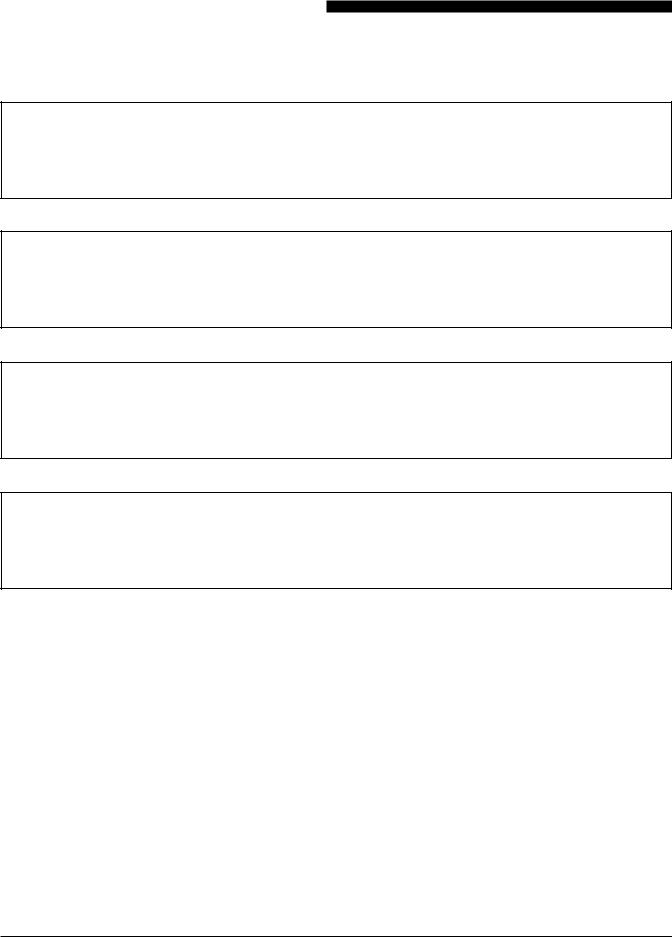
TORTILLA GRILL AND TACO TOWER POWER ON/OFF SWITCHES
Figure 7. Location of Power ON/OFF switches
1:Tortilla Grill
2:Taco Tower Infrared Heaters and Lights
Service Manual for Taco Bell Dual-Line Counters
TheTortillaGrillandTacoTowerON/OFFSwitches arelocatedononesideoftheDryChannelWarmer next to the Dry Channel Display.
1.Place the Main Power ON/OFF Switch in the OFF position. Use proper Lockout/Tagout procedures.
2.Remove the screws securing the switch plate.
3.Remove protective cover, if present, from the back of the switches.
4.Taganddisconnectthewiresfromthesuspect switch.
5.Using an ohmmeter check the switch for continuity. It should read 0 ohms in the ON position and a very high reading in the OFF position. Replace the switch if it fails the continuity tests.
6.Remove two screws on front of control panel to remove faulty switch.
7.Replace existing switch with properly rated switch.
8.Refer to tags and reconnect wires.
9.Install protective cover.
10. Mount switch to mounting plate.
11. Reattach mounting plate to unit.
12. Restore Dual-Line to service and check for proper switch operation.
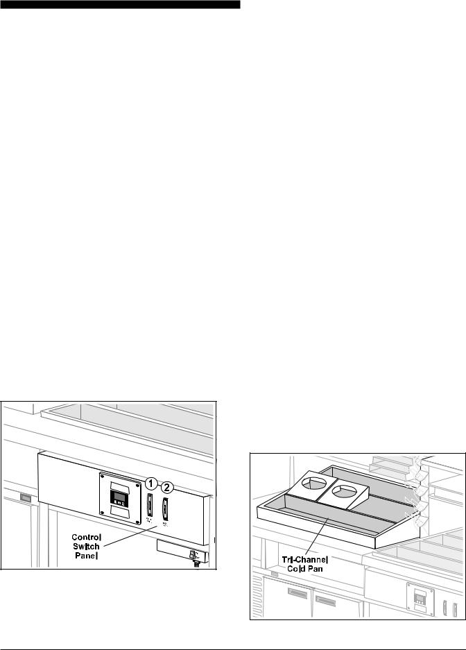
TRI-CHANNEL COLD PAN
Figure 8. Tri-Channel Cold Pan Unit
7
 Loading...