


DUAL HEATSINKTM
HOLDING UNITS
MODELS
HS2-22-T
HS2-23-T
HS2-24-T
HS2-42-T
HS2-34-T
OPERATOR’S MANUAL
U.S. and Foreign Patents Pending
IMPORTANT INFORMATION, READ BEFORE USE. PLEASE SAVE THESE INSTRUCTIONS.
This manual is Copyright © 2018 Duke Manufacturing Company. All rights reserved. Reproduction without written permission is prohibited. Duke is a registered
trademark of the Duke Manufacturing Company.
Duke Manufacturing Company
2305 N. Broadway
St. Louis, MO 63102
Phone: 314-231-1130
Toll Free: 1-800-735-3853
Fax: 314-231-5074 www.dukemfg.com
P/N 229201
REV J 04/16/2018

HS2 Holding Units |
|
Operator’s Manual |
|
TABLE OF CONTENTS |
|
Manufacturer’s Introduction................................................................................................................... |
3 |
Important Safety Instructions................................................................................................................. |
4 |
Installation.............................................................................................................................................. |
5 |
Temperature Verification........................................................................................................................ |
6 |
Stacking Units........................................................................................................................................ |
7 |
Proper Use Of Pan HeatSinkTM Cover & Pan Trivets.............................................................................. |
7 |
Cleaning Guide...................................................................................................................................... |
8 |
HS2-T Operating Instructions............................................................................................................... |
10 |
HS2 Recipe Configuration Guide......................................................................................................... |
12 |
HS2 Recipe Download onto a USB Drive............................................................................................ |
16 |
Downloading the Recipe to the HS2 Unit............................................................................................. |
17 |
Renaming Recipe Files........................................................................................................................ |
19 |
HS2-T Fault Displays on Timer Bars.................................................................................................... |
20 |
Parts Lists And Illustrations.................................................................................................................. |
21 |
HS2-2X2 Specifications....................................................................................................................... |
22 |
HS2-2X2 Wiring Schematics................................................................................................................ |
23 |
HS2-2X3 Specifications....................................................................................................................... |
24 |
HS2-2X3 Wiring Schematics................................................................................................................ |
25 |
HS2-2X4 Specifications....................................................................................................................... |
26 |
HS2-2X4 Wiring Schematics................................................................................................................ |
27 |
HS2-4X2 Specifications....................................................................................................................... |
28 |
HS2-4X2 Wiring Schematics................................................................................................................ |
29 |
HS2-3X4 Specifications....................................................................................................................... |
30 |
HS2-3X4 Wiring Schematics................................................................................................................ |
31 |
2

HS2 Holding Units
Operator’s Manual
MANUFACTURER’S INTRODUCTION
The HS2 Holding Unit was developed specifically to address the needs of restaurant operations and
profitability. Extended hold times with improved food quality and consistency were achieved through the innovative, top and bottom patented Duke technology HeatSink’sTM. This gives you the ability
to maintain gold standard sensory attributes at significantly extended hold times while delivering hotter food to your customers.
In addition to providing the most robust and reliable solution technically possible, we also made the following improvements from the previous FWM PHU model:
•Changed to a more robust Duke timer bar and control system on HS2-T models
•Eliminated plastic lids and replaced with a robust Stainless Steel Pan HeatSink™ Cover for broiled foods
•Incorporated advanced grease migration controls
•Eliminated plastic faceplate and plastic lid capture system
Throughout this manual, you will uncover more details about the benefits and advantages that the Duke HS2 will bring to your restaurant. Thank you for your purchase and as always, your feedback is appreciated.
3
HS2 Holding Units
Operator’s Manual
IMPORTANT SAFETY INSTRUCTIONS
Throughout this manual, you will find the following safety words and symbols that signify important safety issues with regards to operating or maintaining the equipment.

 WARNING

 CAUTION
CAUTION
Indicates a hazardous situation which, if not avoided, could result in death or serious injury.
Indicates a hazardous situation which, if not avoided, could result in minor or moderate injury.
Indicates Important Information
Indicates electrical shock hazard which, if not avoided, could result in death or serious injury and/or equipment damage.
Indicates hot surface which, if not avoided, could result in minor or moderate injury.
In addition to the warnings and cautions in this manual, use the following guidelines for safe operation of the unit.
•Read all instructions before using equipment.
•For your safety, the equipment is furnished with a properly grounded cord connector. Do not attempt to defeat the grounded connector.
•Install or locate the equipment only for its intended use as described in this manual.
•Do not use corrosive chemicals in this equipment.
•Do not operate this equipment if it has a damaged cord or plug, if it is not working properly, or if it has been damaged or dropped.
•This equipment should be serviced by qualified personnel only. Contact the nearest Duke authorized service facility for adjustment or repair.
•Do not block or cover any openings on the unit.
•Do not immerse cord or plug in water.
•Keep cord away from heated surfaces.
•Do not allow cord to hang over edge of table or counter.
The following warnings and cautions appear throughout this manual and should be carefully observed.
•Turn the unit off, disconnect the power source and allow unit to cool down before performing any service or maintenance on the unit.
•The procedures in this manual may include the use of chemical products. You must read the Material
Safety Data Sheets before using any of these products.
•The unit should be grounded according to local electrical codes to prevent the possibility of electrical shock. It requires a grounded receptacle with dedicated electrical lines, protected by fuses or circuit breaker of the proper rating, in accordance with all applicable regulations.
•Disposal of the unit must be in accordance with local environmental codes and/or any other applicable codes.
•This appliance is not intended for use by persons (including children) with reduced physical, sensory or mental capabilities, or lack of experience and knowledge, unless they have been given supervision or instruction concerning use of the appliance by a person responsible for their safety.
4

HS2 Holding Units
Operator’s Manual
INSTALLATION
UNPACKING UNIT
Inspect the shipping carton and/or container, carefully noting any exterior damage on the delivery receipt; also note any damage not evident on the outside of the shipping container (concealed damage). Contact the carrier immediately and file a damage claim with them. Save all packing materials when filing a claim. Freight damage claims are the responsibility of the purchaser and are not covered by the warranty.
•Follow the instructions on the Carton Box for unpacking the unit.
•Inspect unit for damage.
•Report any dents or breakage to source of purchase immediately.
•Do not attempt to use unit if damaged.
•Remove all materials from unit interior.
The following minimum clearances must be maintained between the warmer and any combustible or non-combustible substance:
Unit |
Clearance |
Right Side |
2” |
Left Side |
2” |
Rear |
OPEN |
Floor |
0” |
Proper airflow around unit will cool the electrical components. With restricted airflow, the unit may not operate properly and the life of the electrical components may be reduced. A 2” clearance is recommended at the control side for longer control life expectancy.
•If unit has been stored in extremely cold area, wait a few hours before connecting power.
INSTALLATION CODES AND STANDARDS
In the United States, the HS2 must be installed in accordance with the following:
1.State and local codes.
2.National Electrical Code (ANSI/NFPA No. 70, latest edition) available from the National Fire
Protection Association, Batterymarch Park, Quincy, MA 02269.
3.Vapor Removal from Cooking Equipment, (NFPA96, latest edition) available from NFPA.
4.Sealed to the counter upon which the equipment is placed per NSF/ANSI 4 standard.
In Canada, the HS2 must be installed in accordance with the following:
1.Local codes.
2.Canadian Electrical Code (CSA C22.2 No. 3, latest edition) available from the Canadian
Standards Association, 5060 Spectrum Way, Mississauga, Ontario, Canada L4W 5N6.
UNIT PLACEMENT
•Do not install unit next to, below or above source of heat such as oven or deep fat fryer.
•Install unit on level counter top surface.
•Outlet should be located so that plug is accessible when the unit is in place.
•Do not install unit in the direct path of air-conditioned airflow.

 WARNING

ELECTRICAL SHOCK HAZARD UNIT MUST BE SAFETY GROUNDED, EARTHED.
DO NOT MODIFY, DEFEAT ELECTRICAL CONNECTIONS OR ALTER PLUG.
ELECTRICAL CONNECTIONS


 BEFORE CONNECTING THE UNIT TO THE POWER SOURCE, VERIFY THAT THE VOLTAGE AND PHASE OF THE POWER SOURCE ARE IDENTICAL TO THE VOLTAGE AND PHASE INFORMATION ON THE DATA LABEL.
EARTHING INSTRUCTIONS
THE UNIT MUST BE GROUNDED. Grounding reduces risk of electric shock by providing an escape wire for the electric current if an electrical short occurs. This unit is equipped with a cord having a grounding wire with a grounding plug. The plug must be plugged into a receptacle that is properly installed and grounded.
Consult a qualified electrician or service agent if grounding instructions are not completely
understood, or if doubt exists as to whether the unit is properly grounded.
DO NOT USE AN EXTENSION CORD. If the product power cord is too short, have a qualified electrician install a three-slot receptacle (or the country specific receptacle for International Units). This unit should be plugged into a dedicated circuit with the electrical rating as provided on the product data plate.
5
HS2 Holding Units
Operator’s Manual
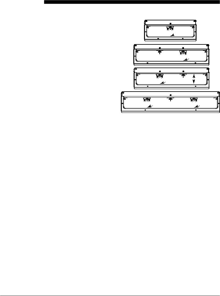
TEMPERATURE CHECK PROCEDURE
1.A digital temperature meter that has been calibrated must be used to get an accurate temperature reading. Use a thermocouple surface temperature probe to measure temperatures.
2. No pans should be in wells during the pre-heat and temperature check. Pre-heat the warmer for 30 minutes before taking any temperature readings. Do not take readings unless the cavity has been empty for 30 minutes. This will allow the temperature to stabilize and will prevent false readings.
3.The warmer cavity should be cleaned and empty before the temperature is checked. Avoid any air drafts that might flow through the cavity.
4.Temperature readings should be taken when standing on the front side of the unit with on/ off switch. Locate the surface temperature probe on the bottom or top of the first cavity. Position the probe half way back on the heat sink beneath the rail as shown. The top readings should be taken on either side of the rail half way back on the heat sink. Four wide units require 2 readings, left and right side.
NOTE: For 2x3 four (4) zone units refer to Fig 3.
Top
OR
 Bottom
Fig 1
2X3 2T
|
|
Top |
|
|
OR |
|
|
Bottom |
1 |
Fig 2 |
2 |
2X3 4T |
|
|
Top |
|
|
OR |
|
|
|
Bottom |
|
3 |
Fig 3 |
4 |
Top |
|
Top |
OR |
|
OR |
Bottom |
|
Bottom |
Fig 4
5.All temperature controls exhibit a swing in temperature as the control cycles on and off while regulating to the set point. The correct calibration temperature is the average of several readings taken over a period of 20 minutes after the warmer has been preheated. The average temperature should be no greater than ± 10°F (± 6°C) from the set point.
6.The allowable range of well temperatures which can be programmed on the HS2 is
140°F-280°F (60°C-137.8°C).
6
HS2 Holding Units
Operator’s Manual
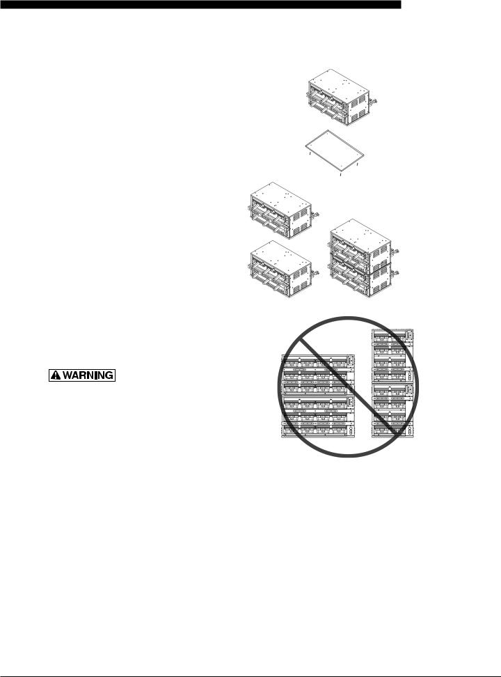
STACKING UNITS
The HS2 Holding Unit is designed to allow limited stacking capabilities. This section outlines how to safely stack the holding unit.
Step 1 |
Remove the base pan from the unit that will be on |
|
top. The pan is held in place by four screws on the |
|
bottom of the unit. |
Step 2 Place bottom unit into position then stack the next unit on top. The top of the lower holding unit rests inside of the base of the upper unit.
TIP HAZARD! DO NOT
STACK HS2-42 OR HS2-34 UNITS. DO
NOT EXCEED 2 HOLDING UNITS PER
STACK. DO NOT PLACE HOLDING
UNIT STACKS ON SURFACES THAT
MAY EASILY TIP OVER.
PROPER USE OF HEATSINKTM COVERS & PAN TRIVETS
Proper usage of each is important and is outlined below:
Product Type |
Duke Pan Heat Sink Cover |
Broiled |
yes |
Fried |
no |
Consult your Kitchen Operations Manual for any modifications to the above based on your specific food requirements.
7

HS2 Holding Units
Operator’s Manual
CLEANING GUIDE
CAUTION |
Electrical shock hazard. Do not wash with water jet or hose. |
DO NOT USE CAUSTIC CLEANERS, ACIDS, AMMONIA PRODUCTS OR ABRASIVE CLEANERS OR ABRASIVE CLOTHS. THESE CAN DAMAGE THE STAINLESS STEEL AND PLASTIC SURFACES.

 WARNING
 Bottom and sides of warmer wells are very hot and cool slowly.
DAILY CLEANING
•Stainless Steel Surfaces
To prevent discoloration or rust on stainless steel several important steps need to be taken. Stainless steel contains 70-80% iron which will rust. It also contains 12-30% chromium which forms an invisible passive fiilm over the steel surface which acts as a shield against corrosion. As long as the protective layer is intact, the metal will not corrode. If the fiilm is broken or contaminated, outside elements can begin to breakdown the steel and begin to form rust or discoloration.
Proper cleaning of stainless steel requires soft cloths or plastic scouring pads.

 CAUTION
Never use steel pads, wire brushes or scrapers.
Cleaning solutions need to be alkaline based or nonchloride cleaners. Any cleaner containing chlorides will damage the protective fiilm of the stainless steel. Chlorides are also commonly found in hard water, salts and household and industrial cleaners.
If cleaners containing chlorides are used, be sure to rinse repeatedly and dry thoroughly upon completion.
Routine cleaning of stainless steel can be done with soap and water. Extreme stains or grease should be cleaned with a non-abrasive cleaner and plastic scrub pad. It is always good to rub with the grain of the steel. There are also stainless steel cleaners
available which can restore and preserve the fiinish of the steels protective layer.
Early signs of stainless steel breakdown can consist of small pits and cracks. If this has begun, clean thoroughly and start to apply stainless steel cleaners in an attempt to restore the passivity of steel.


 NEVER USE AN ACID BASED CLEANING SOLUTION! MANY FOOD PRODUCTS HAVE AN ACIDIC CONTENT WHICH CAN DETERIORATE THE FINISH. BE SURE TO CLEAN ALL FOOD PRODUCTS FROM ANY STAINLESS STEEL SURFACE. COMMON ITEMS INCLUDE, TOMATOES, PEPPERS AND OTHER VEGETABLES.


 THE POWER MUST BE TURNED OFF AND DISCONNECTED AT ALL TIMES WHEN PERFORMING
MAINTENANCE OR REPAIR FUNCTIONS.
CAUTION NEVER USE A HIGHPRESSURE WATER WASH FOR THIS CLEANING PROCEDURE AS WATER CAN DAMAGE ELECTRICAL COMPONENTS
CAUTION ELECTRICAL SHOCK HAZARD. DO NOT WASH WITH WATER JET OR HOSE.
RECOMMENDED SUPPLIES
Cleaning Towels
Non-Scratch Scrub Pad
KAY™ Degreaser
KAY® SINK SANITIZER, KAYQUAT™ Sanitizer, or compatible sanitizer
8

HS2 Holding Units
Operator’s Manual
PROCEDURE
1.Turn unit off, unplug, and allow to cool for 30 minutes.
2.Remove all holding pans and heat sink covers. Wash, rinse, and sanitize at the 3 compartment sink.
3.Allow to air dry.
4.Spray a cleaning towel, or non-scratch scrub pad when necessary, with soapy solution or KAY™ Degreaser. Fully clean upper heat sink surfaces by hand, as well as lower heat sink surfaces.
CAUTION Take care when reaching in the cabinet. Pan and lid guides present sheet metal edges which could be sharp.
NOTE: Never spray cleaning solution directly onto the cabinet.
5.If daily cleaning is performed routinely, deeper, more aggressive, cleaning methods can be avoided. Over longer periods of time, fried food product can accumulate and bake on to the upper heat sink surfaces of the compartments.
6.Use a sanitizer-soaked towel and wipe out all compartments on the holding unit. Wipe top compartments first, and then lower compartments.
IMPORTANT: Use clean, sanitizer-soaked towels (Important: towels must be wrung out so that they are damp and not dripping, dripping towels may harm the unit.)
DAILY INSPECTION CHECKLIST:
Make sure that:
•Unit is free of any visible food soils.
•Unit is free of grease or soils in holding compartment.
•Exterior of unit is free of smudges or soil.
•Holding pans are free of any food soil residue.
•Pans are free of damage such as cracks.
9

HS2 Holding Units
Operator’s Manual
HS2-T OPERATING INSTRUCTIONS
TO ENSURE OPTIMAL HOLD QUALITY, THE USER WOULD PRESS THE BUTTON ON THE TIMER BAR CORRESPONDING WITH THE PAN LOCATION TO ACTIVATE A HOLD CYCLE.
THIS STARTS THE TIMER COUNTDOWN.
1 |
2 |
3 |
3 |
2 |
1 |
1.Status LED’s: Indicates status of the pan
a.Non-Illuminated – timer is inactive – no product in pan.
b.Green – timer is active – product in pan (use 1ST)
c.Amber – timer is active – product in pan (use next)
d.Non-Illuminated – timer active – product in pan
(use later)
e.Flashing Green – cook warning time reached
(cook more product)
f.Flashing Red – product is expired (discard)
2.Arrow buttons
a.Used for starting and stopping the timer
b.Used to access menu mode
c.Indicates which pan the adjacent status LED and pan display are linked to
3.Pan Display
•ENSURE PROPER HEAT SINK COVERS ARE INSERTED INTO THE CORRECT LOCATION (BROILED AND MOISTURE SENSITIVE PRODUCTS ONLY).
•ENSURE METAL TRIVETS ARE INSERTED INTO THE PANS FOR FRIED PRODUCTS.
•UPON TURNING ON, ALLOW THE HOLDING UNIT TO HEAT FOR AT LEAST 30 MINUTES OR UNTILTHE TEMPERATURE DISAPPEARS AND THE TIMER BARS DISPLAY THE PREPROGRAMMED PRODUCT NAMES.
•IF THE TIMER BARS DISPLAY “HIGH” OR “LOW” AT ANY TIME AFTER THE PRE-HEAT PERIOD, DISCONTINUE USE OF THE AFFECTED PAN LOCATION(S) UNTIL THE HOLDING UNIT CAN BE SERVICED.
a.In startup mode it will display spinning bars then transition to PRE HEAT, and then cycle through the bottom actual temp and top actual temp
b.Once unit reaches the recipe set points it will display product name. (If associated recipe requires a lid display will toggle prod name, lid.)
c.Unit will display product name and hold time remaining
(display will alternate between the two when a timer is active)
10
 Loading...