


Service Manual
BAKING CENTER
AHPO / EPO
PROOFER OVEN
MODELS
AHPO-6/18
EPO-3/9
Please read this manual completely before attempting to install, operate or service this equipment
This document is prepared for trained Duke service technicians. It is not to be used by anyone not properly qualified to perform these procedures.
This Service Manual is not all encompassing. If you have not been trained on servicing this product, be sure to read the manual completely before attempting servicing. Be sure all necessary tools, test equipment, and skills are available. Those procedures for which you do not have the proper skills and test equipment must be performed only by a qualified Duke trained service technician.
This manual is Copyright © 2009 Duke Manufacturing Co. All rights reserved. Reproduction without written permission is prohibited. Duke is a registered
trademark of the Duke Manufacturing Co.
Duke Manufacturing Co.
2305 N. Broadway
St. Louis, MO 63102
Phone: 314-231-1130
Toll Free: 1-800-735-3853
Fax: 314-231-5074 www.dukemfg.com
P/N 512981B

Service Manual for AHPO / EPO Proofer Oven
IMPORTANT WARNING AND SAFETY INFORMATION
IMPORTANT FOR YOUR SAFETY
READ THIS MANUAL THOROUGHLY BEFORE OPERATING, INSTALLING OR PERFORMING
MAINTENANCE ON THE EQUIPMENT.


 Failure to follow instructions in this manual can cause property damage, injury or death.
|
|
Do |
not |
store or |
use gasoline or other flammable vapors or liquids |
|
|
||||
|
|
||||
in the vicinity of |
this |
or any |
other appliance. |
||


 This unit is designed for a fixed, permanent (hard) wired connection to an appropriate AC power source as stated on the model label. The external wiring interface must be installed as per the local AC wiring codes.


 Always lockout / tagout the unit from the main AC power source before removing any sheet metal panels or attempting to service this unit. Failure to comply to this procedure may cause property damage, injury or death.


 Improper installation, adjustment, alteration, service or maintenance can cause property damage, injury or death. Read the installation, operating and maintenance instructions thoroughly before installing or servicing this equipment.
 Do not operate this equipment without properly placing and securing all cover and access panels.


 In the event of a power failure, do not attempt to operate this device.
2

Service Manual for AHPO / EPO Proofer Oven |
|
TABLE OF CONTENTS |
|
INTRODUCTION............................................................................................................................................ |
4 |
INSTALLATION..................................................................................................................................... |
4 |
OPERATION........................................................................................................................................... |
4 |
CLEANING............................................................................................................................................. |
4 |
TOOLS ......................................................................................................................................................... |
4 |
STANDARD............................................................................................................................................ |
4 |
SPECIFICATIONS........................................................................................................................................... |
5 |
REMOVALAND REPLACEMENT OF COMPONENTS............................................................................. |
6 |
ELECTRICAL LOCKOUT/TAGOUT PROCEDURE........................................................................... |
6 |
COVERS AND PANELS......................................................................................................................... |
6 |
General Service Notes..................................................................................................................... |
6 |
Proofer Rear Panel.......................................................................................................................... |
6 |
Oven Rear Panels............................................................................................................................ |
6 |
Oven Fan Cage and Wire Harness Cover........................................................................................ |
7 |
Proofer Floor Panel......................................................................................................................... |
7 |
Oven Ceiling Panel.......................................................................................................................... |
8 |
Control Panel................................................................................................................................... |
8 |
AC Power Access Panel.................................................................................................................. |
9 |
AC INPUT VOLTAGE WIRING CONNECTIONS............................................................................... |
9 |
INTERNAL LAMP REPLACEMENT.................................................................................................... |
9 |
CONTROL PANEL COOLING FAN.................................................................................................... |
10 |
PROOFER LIGHTS CIRCUIT BREAKER.......................................................................................... |
10 |
BUZZER................................................................................................................................................ |
11 |
OVEN POWER SWITCH..................................................................................................................... |
12 |
OVEN THERMOSTAT......................................................................................................................... |
12 |
OVEN TIMER....................................................................................................................................... |
12 |
PROOFER POWER SWITCH.............................................................................................................. |
13 |
PROOFER THERMOSTAT................................................................................................................... |
13 |
PROOFER HUMIDITY CONTROL..................................................................................................... |
14 |
PROOFER TIMER................................................................................................................................ |
14 |
PROOFER HEAT ELEMENTS............................................................................................................ |
15 |
PROOFER HUMIDITY ELEMENT..................................................................................................... |
15 |
PROOFER CIRCULATION FAN......................................................................................................... |
16 |
OVEN HEAT ELEMENTS................................................................................................................... |
17 |
OVEN CIRCULATION FAN................................................................................................................ |
17 |
OVEN HI-LIMIT THERMOSTAT........................................................................................................ |
18 |
DOOR GASKET REPLACEMENT..................................................................................................... |
18 |
OVEN SAFETY SWITCH.................................................................................................................... |
18 |
ADJUSTMENTS............................................................................................................................................ |
19 |
DOOR GASKET COMPRESSION CHECK........................................................................................ |
19 |
DOOR GASKETADJUSTMENTS...................................................................................................... |
19 |
AIR WASH DOOR ADJUSTMENT..................................................................................................... |
20 |
Air Wash Door Adjustment – Hinge Side..................................................................................... |
20 |
Air Wash Door Adjustment – Handle Side............................................................................................ |
20 |
MAINTENANCE........................................................................................................................................... |
21 |
STAINLESS STEEL CARE.................................................................................................................. |
21 |
GENERAL CLEANING........................................................................................................................ |
21 |
TROUBLESHOOTING................................................................................................................................. |
22 |
ELECTRICAL SCHEMATIC........................................................................................................................ |
23 |
3

Service Manual for AHPO / EPO Proofer Oven
INTRODUCTION
INSTALLATION
For detailed installation instructions, refer to the Owner’s Manual (502821A).
OPERATION
For specific operating instructions, refer to the Owner’s Manual (502821A).
CLEANING
For specific instructions, refer to the Owner’s Manual (502821A).
TOOLS
STANDARD
•Standard set of hand tools.
•VOM with AC current tester. (Any quality VOM or DVM with a sensitivity of at least 20,000 Ohms per Volt can be used.)
•Aladderorotherappropriateitemtostandon,ifservicing the top of the unit.
4
Service Manual for AHPO / EPO Proofer Oven
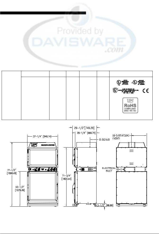
SPECIFICATIONS
U.S. Patent. Other US and Foreign Patents Pending
Model AHPO or EPO
Shipping Weight: |
|
Carton Box |
625 lbs / 284 kg |
|
|
|
|
Shipping Weight: |
|
Wooden Crate |
760 lbs / 345 kg |
|
|
|
Volts |
Phase |
Hz |
Watts |
Amps |
|
208 |
1 |
60 |
6650 |
32.0 |
|
208 |
1 |
50 |
6650 |
32.0 |
AHPO / |
230 (220-240) |
1 |
60 |
6650 |
32.0 |
EPO |
230 (220-240) |
1 |
50 |
6650 |
32.0 |
|
230 (220-240) |
3 |
60 |
6650 |
16.7 |
|
230 (220-240) |
3 |
50 |
6650 |
16.7 |
|
400 (380-415) |
3N |
60 |
6650 |
16.7 |
|
400 (380-415) |
3N |
50 |
6650 |
16.7 |
5
Service Manual for AHPO / EPO Proofer Oven
REMOVALAND REPLACEMENT OF COMPONENTS
ELECTRICAL LOCKOUT/TAGOUT
PROCEDURE


 Before performing any service that involves electrical connection or disconnection and/or exposure to electrical components, always follow the Electrical LOCKOUT/TAGOUT Procedure. Disconnect all circuits. Failure to comply can cause property damage, injury or death.
The Electrical LOCKOUT/TAGOUT Procedure is used to protectpersonnelworkingonanelectricalappliance.Before performinganymaintenanceorservicethatrequiresexposure to electrical components, follow these steps:
1.In electrical box, place appliance circuit breaker into OFF position.
2.Place a lock or other device on electrical box cover to prevent someone from placing circuit breaker ON.
3.Place a tag on electrical box cover to indicate that appliance has been disconnected for service and power should not be restored until tag is removed by maintenance personnel.
4.Disconnectappliancepowercordfromelectricaloutlet.
5.Place a tag on the cord to indicate that unit has been disconnectedforserviceandpowershouldnotberestored until tag is removed by maintenance personnel.
COVERS AND PANELS


 Disconnect the electrical power to the unit and follow lockout / tagout procedures.


 Interior components and surfaces may be hot if the unit has been in recent use.
General Service Notes
•Thisunituseswatertraysforhumiditycontrol.Remove any water that might be present in the trays before attempting service of any kind.
•Duringitsinstallation,thisunitisrequiredtobesecuredto thebuildingstructure.ThereisalsoaRestrainingDevice (aheavy,flexiblemetalcable)thatwasinstalledtoprevent the unit from moving beyond a certain distance in order to prevent damage to the electrical conduit feeding it.
Most service can be accomplished without moving the unit from its mounted position. However, if the unit is moved during service, then these securing devices must be reinstalled for continued protection against tip-over and to meet other compliance regulations.
Proofer Rear Panel


 Disconnect the electrical power to the unit and follow lockout / tagout procedures.
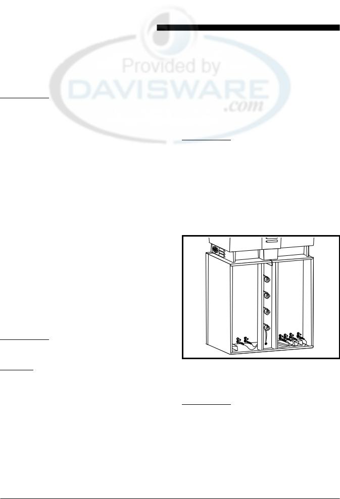
RemovingtheProoferRearPanel,gainsaccesstotheProofer Light Fixtures, Proofer Burners connections, and Proofer Wiring Harnesses.
1.Remove all of the self-tapping sheet metal screws that securetheRearPaneltotheProofer.Setasideforreuse.
2.RemovetheRearPaneltogainaccesstothecomponents located at the rear of the Proofer.
Figure 1. Proofer – Rear Panel Removed
Oven Rear Panels
 Disconnect the electrical power to the unit and follow lockout / tagout procedures.
TheOvensectionoftheunithasthreerearpanels.TheCenter Panel provides access to the Oven Light Fixtures and Oven Light Fixture wiring harness. Right and Left Panels provide accesstotheOvenBurnerElementconnectionsandElement wiring harnesses.
1.Remove the screws securing the Center Panel. Retain for reuse.
6
2.RemovetheCenterPaneltogainaccesstoLightFixtures and wiring harness.


 The Center Panel side screws must be removed when removing either of the side panels.
3.RemovethescrewssecuringtheSidePanels.Retainfor reuse.
4.Carefully remove the insulation to gain access to the Oven Burner Element connections and Oven Burner Elementwiringharness.Retaintheinsulationforreuse.
Figure 2. Oven – Right Side Panel Removed
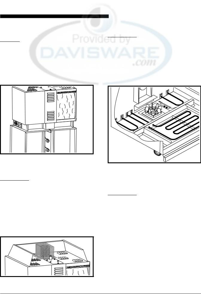
Oven Fan Cage and Wire Harness Cover
 Disconnect the electrical power to the unit and follow lockout / tagout procedures.
1.Remove the four screws securing the Oven Fan Cage to the top of the unit. Retain for reuse.
2.RemovetheCagetogainaccesstotheOvenFanMotor.
3.RemovethescrewssecuringtheOvenFanWireHarness Cover to top of unit. Retain for reuse.
4.Remove the Oven Fan Wire Harness Cover to gain access to the wiring harness and connections.
Figure 3. Oven Fan Cage and
Wire Harness Cover
Service Manual for AHPO / EPO Proofer Oven
Proofer Floor Panel


 Disconnect the electrical power to the unit and follow lockout / tagout procedures.
1.Remove screws securing the Proofer Floor Panel.
2.Slide the panel out through the front of the unit being careful not to damage the fan blades.
Access to the Proofer Heater Elements, Humidity Element, Proofer Circulating Fan and Sensor is available with the Proofer Floor Panel removed.
Figure 4. Proofer Components with
Floor Panel Removed
Oven Ceiling Panel


 Disconnect the electrical power to the unit and follow lockout / tagout procedures.
1.Remove the Humidity Pan.
2.Remove the screws securing the panel. Retain screws for reuse.
3.It may be necessary to pry the panel forward from the front of the unit. Be careful not to damage the fan blade when removing the panel.
Access to Oven Heating Elements, Fan Blade and Sensors is available with the Oven Ceiling Panel removed.
7

Service Manual for AHPO / EPO Proofer Oven
Figure 5. Oven Components with Ceiling Panel Removed
Control Panel


 Disconnect the electrical power to the unit and follow lockout / tagout procedures.
It is not necessary to move the unit to gain access to the Control Panel. It might become necessary to remove the unit from the wall if troubleshooting leads into other areas. Refertothespecificcomponentsectionofthismanualwhen replacing a component on the Control Panel.
1.Remove the four screws retaining the Control Panel to the cabinet.
2.Carefully pull the front panel assembly away from the cabinetwhileobservingclearancesofthewiringaround the controls.
All of the Operator Controls and related wiring are now accessible.


 DO NOT power on the unit while the Control Panel is removed from the cabinet.
3.To troubleshoot for problems, use visual checks, an Ohmmeter,theproperSchematicandIllustrationspages for the version of the unit being serviced.
Figure 6. Components on Left Side of Control Panel
Figure 7. Components on Right Side of Control Panel


 When reassembling, make sure that wires do not become pinched between the Control Panel and the cabinet surfaces.
4.Replaceall securing screws to the Control Panel before re-powering the unit.
AC POWER ACCESS PANEL


 Disconnect the electrical power to the unit and follow lockout / tagout procedures.
8
 Loading...