


Installation and
Operation Manual
X-STREAM WASH
Please read this manual completely before attempting to install, operate or service this equipment
This manual is Copyright © 2013 Duke Manufacturing Co. All rights reserved. Reproduction without written permission is prohibited. Duke is a registered
trademark of the Duke Manufacturing Co.
Duke Manufacturing Co.
2305 N. Broadway
St. Louis, MO 63102
Phone: 314-231-1130
Toll Free: 1-800-735-3853
Fax: 314-231-5074 www.dukemfg.com
P/N 115152F

Installation and Operation of X-STREAM WASH
2

Installation and Operation of X-STREAM WASH |
|
TABLE OF CONTENTS |
|
I. GENERAL INFORMATION............................................................................................. |
6 |
A. X-STREAM WASH SPECIFICATION..................................................................... |
6 |
II. INSTALLATION INSTRUCTIONS.................................................................................. |
7 |
A. QUALIFIED PERSONNEL...................................................................................... |
7 |
B. DELIVERY AND INSPECTION............................................................................... |
7 |
C. PLACEMENT.......................................................................................................... |
7 |
D. PLUMBING REQUIREMENTS............................................................................... |
7 |
E. ELECTRICAL CONNECTIONS.............................................................................. |
8 |
F. XSTREAM WASH OPTIONS.................................................................................. |
8 |
III. OPERATION INSTRUCTIONS..................................................................................... |
9 |
A. INITIAL STARTUP.................................................................................................. |
9 |
A-10 Fill Tanks with Water................................................................................... |
9 |
A-20 Add Soap / Chemicals................................................................................ |
9 |
A-30 Approved Chemicals.................................................................................. |
9 |
B. PRE-SCRAPPING................................................................................................ |
10 |
C. LOADING WASH TANK....................................................................................... |
10 |
D. START THE WASH CYCLE................................................................................. |
11 |
E. CONTROL PANELS............................................................................................. |
11 |
E-10 Identifying Your Control Panel................................................................... |
11 |
E-20 K1000 Control Panel................................................................................. |
12 |
E-30 K5000 Control Panel................................................................................. |
19 |
E-40 Wash Cycle Defaults................................................................................. |
28 |
IV. SERVICE AND REPAIR.............................................................................................. |
30 |
V. ELECTRICAL SCHEMATICS....................................................................................... |
32 |
3

Installation and Operation of X-STREAM WASH
SAFETY AND ELECTRICAL WARNINGS
THIS MANUAL HAS BEEN PREPARED FOR PERSONNEL QUALIFIED TO INSTALL ELECTRICAL EQUIPMENT, WHO SHOULD PERFORM THE INITIAL FIELD STARTUP AND ADJUSTMENTS OF THE EQUIPMENT COVERED BY THIS MANUAL.
READ THIS MANUAL THOROUGHLY BEFORE OPERATING, INSTALLING OR PERFORMING MAINTENANCE ON THE EQUIPMENT.


 : Failure to follow all the instructions in this manual can cause property damage, injury or death.


 : Improper installation, adjustment, alteration, service or maintenance can cause property damage, injury or death.


 : Electrical connections should be performed only by a certified professional.


 : Electrical and grounding connections must comply with the applicable portions of the National Electrical Code and/or all local electric codes. Failure to comply with this procedure can cause property damage, injury or death.


 : Plumbing connections must comply with applicable sanitary, safety and plumbing codes.


 : Before connecting the unit to the electrical supply, verify that the electrical and grounding connections comply with the applicable portions of the National Electrical Code and/or other local electrical codes. Failure to comply with this procedure can cause property damage, injury or death.


 : Before connecting the unit to the electrical supply, verify that the electrical connection agrees with the specifications on the data plate. Failure to comply with this procedure can cause property damage, injury or death.
 : UL73 grounding instructions: This appliance must be connected to a grounded, metal, permanent wiring system or an equipment-grounding conductor must be run with the circuit conductors and connected to the equipment-grounding terminal or lead on the appliance. Failure to comply with this procedure can cause
property damage, injury |
or death. |
||
|
|
: Before |
performing any service that involves electrical connection |
|
|
||
|
|
||
|
|
||
or disconnection and/or exposure to electrical components, always perform the Electrical LOCKOUT/TAGOUT Procedure. Disconnect all circuits. Failure to comply with this procedure can cause property damage, injury or death.
4

Installation and Operation of X-STREAM WASH


 : Before removing any sheet metal panels or servicing this equipment, always perform the Electrical LOCKOUT/TAGOUT Procedure. Be sure all circuits are disconnected. Failure to comply with this procedure can cause property damage, injury or death.


 : Do not operate this equipment without properly placing and securing all covers and access panels. Failure to comply with this procedure can cause property damage, injury or death.


 : Do not use or store gasoline or other flammable vapors or liquids in the vicinity of this or any other appliance. Failure to comply can cause property damage, injury or death.


 : In the event of a power failure, do not attempt to operate this appliance. Failure to comply can cause property damage, injury or death.
5
Installation and Operation of X-STREAM WASH
I.GENERAL INFORMATION
A.X-STREAM WASH SPECIFICATION
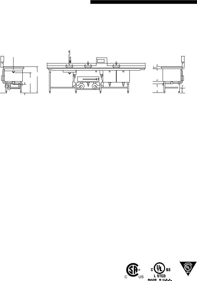
DIMENSIONS:
|
3" |
|
37" |
18" |
|
BOWL |
||
28-7/8" |
DEPTH |
|
DRAIN |
|
|
12" |
6" |
|
12" |
||
DRAIN |
||
|
MODEL NUMBER KEY:
SSSTUVW-XXYY with suffixes. Where:
SSSIndicates the type of unit
XSW – Denotes an X-Stream wash unit
TIndicates the options
– – Denotes no options
H – Denotes the heated sanitizer sink option
C – Denotes that chemical injection sanitizer sink option
UIndicates the controller model number
1 – K1000 Control (Not available on units with a heated sanitizer sink) 5 – K5000 Control
VIndicates the heating element wattage used in the powered wash sink 2 – 2500 watt
5 – 5000 watt
7 – 7000 watt (Not available on 208-240 VAC units that have a heated sanitizer sink)
WIndicates the number of soap pumps on the unit 0 – No Wash Sink Soap Pumps
1 – With Wash Sink Soap Pump
XXIndicates the overall length of the powered wash sink in inches 36 – 36 inches
42 – 42 inches
48 – 48 inches
54 – 54 inches
60 – 60 inches
72 – 72 inches
YYIndicates the overall width of the powered wash sink in inches
26 – 26-1/2 inches
28 – 28 inches
Voltage and Phase will be handled separately from the model number. |
|
|
|
ANSI/NSF 2 |
|
B45 ONLY |
|||||
|
|||||
They will be listed on the rating tag located in the Control Panel. |
|
|
|||
|
|
|
|
|
|
6
Installation and Operation of X-STREAM WASH
II. INSTALLATION INSTRUCTIONS
A. QUALIFIED PERSONNEL
Theseinstallationinstructionsarefortheuseofqualified installation and service personnel only. Installation or service by other than qualified personnel may result in damage to the unit and/or injury to the operator.
Qualified installation personnel are those individuals, firms,companiesorcorporationswhicheitherinperson or through an agent is engaged in and responsible for:
•The installation of electrical wiring from the electric meter, main control box or service outlet to the electricalappliance.Qualifiedinstallationpersonnel must be familiar with all precautions required and have complied with all requirements of state and local authorities having jurisdiction. See: National Electrical Code, ANSI/NFPA70.
•This appliance is not intended for use by persons
(including children) with reduced physical, sensory or mental capabilities, or lack of experience and knowledge,unlesstheyhavebeengivensupervision or instruction concerning use of the appliance by a person responsible for their safety.
B. DELIVERY AND INSPECTION
Duke Manufacturing Co. does everything within its powertoensureyoureceivedyourunitingoodcondition. They are crated on heavy wooden skids and packed to prevent shipping damage. They have all been carefully inspected before they were packaged and consigned to the carrier.
Upon delivery of your Duke unit:
•Look over the shipping container, carefully noting any exterior damage on the delivery receipt, which must also be signed by the driver/ delivery person.
•Unpack and check for any damage, which was not evident on the outside of the shipping container.
•Check for concealed damage. The carrier must be notified within fifteen (15) days of the delivery of the unit and the crate and all packaging materials must be retained for inspection.
Duke Manufacturing Co. cannot assume liability for loss or damage suffered in transit. The carrier assumes full responsibility for delivery in good order when the shipment was accepted. However, we are prepared to assist you in filing your claim.
C. PLACEMENT
•HANDLING – The units are very heavy and may require the use of moving equipment. Consult with your local restaurant equipment supplier.
•INSPECTION – Inspect the area where the unit is being installed. Check for proper clearance with shut off valves and drain line hook ups.
•LEVELING – The unit is equipped with adjustable bullet feet. Use a wrench or pliers to adjust up or down.
•SEALING – Seal the top of the backsplash to the wall using an NSF approved silicone sealant.


 : Equipment is heavy. Heavy lifting may result in bodily injury. Do not lift or move without adequate help.
D. PLUMBING REQUIREMENTS
•WATER SUPPLY – Hot and Cold Water should be supplied by ½” or ¾” water lines, with the ¾” being the preferred method.
•DRAINS – A 1-1/2” minimum waste connection is required. If equipped, the scrapping sink should have a 1-1/2” NPS connection, while the wash, rinse, and sanitize sinks typically have a 2” NPS connection.
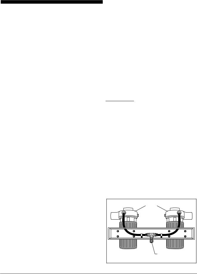
•PUMPS – The wash tank pumps will need to be piped to a floor drain. This uses a ½” NPT connection.
Pump
Pipe this connection to floor drain
Bottom View of Pump Assembly
7
Installation and Operation of X-STREAM WASH
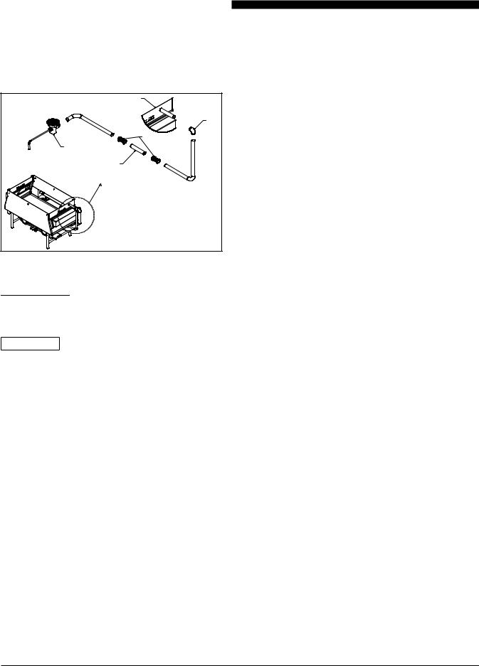
•Any plumbing overflows for the unit are shipped uninstalled and will need to be installed during installation. See below for a depiction of the main tank overflow (Note: A main tank overflow is an option and is not provided on some units).
WASH TANK
ELBOW
COUPLES
DRAIN
EXTRA TUBING
USED ON 60" & 72"
TANKS ONLY
Overflow Kit (Optional)
E. ELECTRICAL CONNECTIONS


 : Electrical Hazard – May result in electrical shock, burns, or death.
CAUTION: Terminal block is phase sensitive. Improper phase can cause incorrect pump rotation. Pump rotation must be verified during installation.
Your unit is supplied for connection to a 208, 240 or 480 volt grounded circuit. The electric motor, indicator lights and control circuit are connected internally and require no secondary power supply.
Before making any connections to these units, check the rating plate to ensure that the voltage and phase of the unit is compatible with the electrical supply. When installing, all units must be electrically grounded in accordancewithlocalcodes,orintheabsenceoflocal codes, with the National Electrical Code, ANSI/NFPA
70 (in Canada - CSA Std. C22.2). Wiring diagrams are located in the control compartment area of the unit. Standard wiring schematics are also provided with this manual.
To ensure service reliability and safety, use water-tight connections and the proper wire gauge.Awire diagram is located inside the control panel lid and also at the back of this manual.
F. XSTREAM WASH OPTIONS
ITEM |
PART NAME |
PART |
|
|
NO. |
1 |
Scrap Basket, X-Stream Engine, |
115749 |
|
26.5" |
|
2 |
Scrap Basket, X-Stream Engine, |
115650 |
|
28" |
|
3 |
Pan Rack, Fixed, 26.5" Wide by |
115800 |
|
60" Long Unit |
|
4 |
Pan Rack, Fixed, 28" Wide by |
115801 |
|
60" Long Unit 1 |
|
5 |
Pan Rack, Adjustable, 26.5" |
115811 |
|
Wide by 36" Long Unit |
|
6 |
Pan Rack, Adjustable, 26.5" |
115812 |
|
Wide by 42" Long Unit |
|
7 |
Pan Rack, Adjustable, 26.5" |
115813 |
|
Wide by 48" Long Unit |
|
8 |
Pan Rack, Adjustable, 26.5" |
115814 |
|
Wide by 54" Long Unit |
|
9 |
Pan Rack, Adjustable, 26.5" |
115815 |
|
Wide by 60" Long Unit |
|
10 |
Pan Rack, Adjustable, 26.5" |
115816 |
|
Wide by 72" Long Unit |
|
11 |
Pan Rack, Adjustable, 28" Wide |
115817 |
|
by 36" Long Unit |
|
12 |
Pan Rack, Adjustable, 28" Wide |
115818 |
|
by 42" Long Unit |
|
13 |
Pan Rack, Adjustable, 28" Wide |
115819 |
|
by 48" Long Unit |
|
14 |
Pan Rack, Adjustable, 28" Wide |
115820 |
|
by 54" Long Unit |
|
15 |
Pan Rack, Adjustable, 28" Wide |
115821 |
|
by 60" Long Unit |
|
16 |
Pan Rack, Adjustable, 28" Wide |
115822 |
|
by 72" Long Unit |
|
17 |
Pan Rack, Drop-in |
115891 |
18 |
Basket, Skewer |
115833 |
19 |
Basket, Utensil |
115653 |
8
Installation and Operation of X-STREAM WASH
III. OPERATION INSTRUCTIONS
A. INITIAL STARTUP
A-10 Fill Tanks with Water
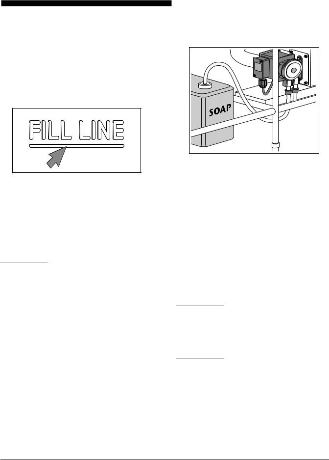
• WASH TANK – Fill wash tank with hot water to the marked Fill Line. The water temperature should be
110˚ to 115˚ F (43˚ to 46˚ C).
Fill Line
•RINSE TANK – If equipped, fill the rinse tank with hot water to the marked Fill Line. The water temperature should 75˚ to 80˚ F (24˚ to 27˚ C).
•SANITIZE TANK – If equipped, fill the sanitize tank with hot water to the marked Fill Line. The water temperature should 75˚ to 80˚ F (24˚ to 27˚ C).


 : Do not connect to hot-water supply exceeding a temperature of 115°F (46°C).
A-20 Add Soap / Chemicals
•WASH TANK – If your unit is equipped with the soap injection option, then make sure that the soap pump pick up tube is inserted into the soap container. The soap will automatically be injected into the wash tank. Otherwise, manually add the soap into the wash tank in accordance with the chemical supplier's instructions.
Soap Pump Installation
•SANITIZETANK–Ifequipped,addtheappropriate sanitizing chemical to the sanitize tank. Consult chemical supplier and your local health code.
A-30 Approved Chemicals
It is recommended that chemicals that are low to non foaming, metal safe, and non-caustic be used in the wash and sanitize tank.
Caustic chemicals are capable of burning, corroding, or destroying living tissue and should not be used. If youplanonusingcausticchemicals,thenarollinglidis required. If your unit did not come with a rolling lid, one can be ordered from the factory. Contact information is provided on the inside cover of this manual.


 : Chemicals used in the wash tank that do not have de-foaming capabilities will not run properly and could damage the machine. Consult your chemical supplier before use.


 : Chemical Hazard - could result in serious injury or death. Always consult with your chemical supplier and read all warning labels before handling new chemicals.
9

Installation and Operation of X-STREAM WASH
B. PRE-SCRAPPING
Wares should be scrapped, NOT SCRUBBED, prior to loading to remove heavy soils and debris. This will improve wash results, reduce chemical costs and reduce the number of water changes needed during the day.
Use the scrapping sink (if equipped) or scrap the wares in a separate waste area close to the unit. Do not scrape wares directly into the wash tank.
Pre-Scrapping
C. LOADING WASH TANK
Pots and Pans
Pots, pans, mixing bowls, etc. can be placed into the wash tank in any order.
Loading Wash Tank
NOTE: Pots and Pans that are stacked or nested together during the wash cycle will not be cleaned properly. Pause the cycle and move them apart from one another.
Utensils and Silverware
Utensils and silver ware must be placed in a utensil basket.
If your unit was not supplied with a utensil basket, one can be ordered from the factory. Contact information is provided in the Customer Assistance section of this manual.
To use the utensil basket, simply hang the basket over the side of the wash tank, place the utensils and silver ware in the basket, and run a wash cycle.
Hang |
Silverware |
Basket |
Utensil Basket Placement
 : To prevent bodily injury never load knives or other sharp objects into the machine.
Sheet Pans
Load sheet pans as described below to ensure the best washing methods.
Ifyourunitwassuppliedwithasheetpanrack,placethe rack into the wash tank in a vertical position (opening on top). Load the rack with sheet pans, and then pivot the rack to a horizontal position.
To load sheet pans without the rack, insert the sheet pans into the wash tank one at a time with the baking side up. Place the pans in an alternating crisscross pattern,soasnottohavethemnest insideofeachother.
10
It is recommended that not more than 10 to 12 pans be placed in the wash tank during a wash cycle.
If your unit did not come with a sheet pan rack, one can be ordered from the factory. Contact information is provided in the Customer Assistance section of this manual.
D. START THE WASH CYCLE
After the wash tank has been loaded, press the cycle start button. Which button you press will be determined by which controller that has been installed on your unit. See the Control Panels section of this manual for more details.
Unload Wash Tank
The display will indicate that the items are clean when a wash cycle has been completed. At this time the system will switch to a holding cycle. This cycle has slower water movement that will keep grease and soiled sediments from falling back onto the items that were just cleaned.
Remove the clean items from the wash tank and dip into the rinse tank to rinse off any soap or soil residue.
Place items into Rinse Tank
Place items into the sanitize tank and soak according to the chemical supplier's instructions and in accordance with local health code.
Remove the item and allow to air dry when sanitization is complete.
Installation and Operation of X-STREAM WASH
Soak in |
Sanitizer |
Place items into Sanitize Tank
E. CONTROL PANELS
E-10 Identifying Your Control Panel
There are two types of control panels used, the K1000 and the K5000. Your control type is printed on the front panel. Use the diagrams below to determine which control you have.
K-1000 CONTROL CENTER |
® |
|
|
|||
|
|
Heater |
|
|
|
|
|
|
Alarm |
|
|
|
|
|
|
Change Water |
|
|
|
|
|
|
Soap |
|
|
|
|
|
|
|
! WARNING |
|
|
|
TEMP |
|
START |
|
|
|
® |
|
STOP |
|
|
® |
||
|
|
|
|
Disconnect power before |
Your Solutions Partner |
|
|
|
|
|
Hazardous voltage. |
|
|
servicing machine. |
(800) 735-3853 |
®
|
|
|
|
|
|
|
|
|
® |
® |
|
|
|
|
|
|
|
|
Your Solutions Partner |
|
|
|
|
|
|
|
|
|
|
|
(800) 735-3853 |
|
|
|
|
|
|
|
|
|
|
! DANGER |
|
|
|
CYCLE 1 |
CYCLE 2 |
CYCLE 3 |
FRANÇAIS |
ESPAÑOL |
ITALIANO |
|
|
|
|
|
CYCLE 4 |
CYCLE 5 |
STOP 6 |
|
|
|
|
|
|
SOAP |
HEATER |
|
|
|
|
|
CYCLE TYPES: |
|
|
|
|
|
|
|
|
|
1. LIGHT |
|
|
|
|
|
|
UP |
|
|
|
2. MEDIUM |
|
Disconnect power before |
|
|
|
|
|
|
|
|
3. NORMAL |
|
servicing machine. |
|
|
|
|
|
|
|
|
4. HEAVY |
|
|
|
|
|
|
DOWN |
|
|
|
5. OVERNIGHT |
|
|
|
|
|
|
|
|
|
|
6. EMERGENCY STOP |
|
|
|
|
|
PUMP SPEED |
|
|
|
|
|
|
|
|
|
|
|
|
|
OPERATING INSTRUCTIONS: |
|
|
||||
1. Fill water to water mark line with HOT |
5. Select wash cycle 1 thru 5 for proper |
|
8. To pause cycle, press the light indicated by |
11. Inspect pots and pans for cleanliness - if |
||||||
water only. CAUTION: Hot water can cause |
|
not clean run a second cycle. |
|
|||||||
personal injury. |
cleaning style, 1 being the lightest to 5 being |
|
the cycle that is running. |
12. After a number of wash cycles, the unit |
||||||
2. Fill rinse tank to water line. |
the most aggressive of wash cycles. |
|
|
9. Press the Stop button to cancel a wash |
||||||
6. Once selection is made note that the |
|
will determine when it is time to change the |
||||||||
3. Fill sanitizer tank to water line (use |
|
cycle. |
|
water, at this time the display will indicate |
||||||
display will indicate “Wash” and the time |
|
10. Rolling lid should be in place during |
“change water”. The system will continue to |
|||||||
approved sanitizer per local health codes). |
remaining. |
|
|
|
|
complete its last wash cycle. However, |
||||
4. If unit has soap option, insert soap pickup |
7. Unit will “Beep” when the cycle is complete |
|
operation, especially during overnight clean- |
before the unit can do another cycle, the |
||||||
|
ing or when caustic soaps are used. |
water must be changed. This ensures maxi- |
||||||||
tube into 5 gallon soap bucket. |
and will display “Clean”. |
|
|
|
|
mum cleaning and sanitizations. |
|
|||
11

Installation and Operation of X-STREAM WASH
E-20 K1000 Control Panel
K-1000 CONTROL CENTER |
® |
 Heater
Alarm
 Change Water
|
Soap |
! WARNING |
TEMP |
START |
|
STOP |
|
|
|
|
|
|
|
|
|
|
Hazardous voltage. |
|
|
Disconnect power before |
|
|
servicing machine. |
® |
® |
|
|
Your Solutions Partner |
|
(800) 735-3853 |
|
K1000 Control Panel
Mylar Buttons
TEMP Button Press to set or display the wash tank's running temperature. When pressed, the display
TEMP will toggle between SP and 115 (115 represents a temperature set point value and may be different on your display), at this time you can press the Up and Down Arrow buttons to change the set point temperature. Once changed, press the Temp button again to lock in the new value.
Down Arrow Button Pressing this button, while not in the temperature set point mode, will display the time remaining before a mandatory water change. Pressing this button while in the temperature set point mode, will lower the temperature set point setting.
Up Arrow Button Pressing this button, while in the temperature set point mode, will raise the temperature set point value. Pressing this button while in the wash mode will display the heater's sheath temperature.
START/STOP Button Pressing this button will toggle on and off the circulation pumps.
START
STOP
Mylar Indicator Lights
Heater |
Heater light will illuminate whenever the wash tank’s heater is powered on. |
Alarm |
Alarm light will illuminate whenever an alarm has occurred. |
Change Water |
Change Water indicator light will flash when it is time to change water. The display will showdrn. |
Soap |
Soap indicator light will illuminate whenever the soap pump is powered on. |
|
12
 Loading...