

D-Link DGS-3000-10TC, DGS-3000-24TC, DGS-3000-26TC Hardware Installation Manual
`

_____________________________________________
Information in this document is subject to change without notice.
© 2014 D-Link Corporation. All rights reserved.
Reproduction in any manner whatsoever without the written permission of D-Link Corporation is strictly forbidden.
Trademarks used in this text: D-Link and the D-LINK logo are trademarks of D-Link Corporation; Microsoft and Windows are registered trademarks
of Microsoft Corporation.
Other trademarks and trade names may be used in this document to refer to either the entities claiming the marks and names or their products. D-
Link Corporation disclaims any proprietary interest in trademarks and trade names other than its own.
June, 2014 P/N 651GS3000035G
This equipment has been tested and found to comply with the limits for a Class A digital device, pursuant to Part 15 of
the FCC Rules. These limits are designed to provide reasonable protection against harmful interference when the
equipment is operated in a commercial environment. This equipment generates, uses, and can radiate radio
frequency energy and, if not installed and used in accordance with this manual, may cause harmful interference to
radio communications. Operation of this equipment in a residential area is likely to cause harmful interference in
which case the user will be required to correct the interference at his own expense.
FCC Warning
This is a Class A product. In a domestic environment, this product may cause radio interference in which case the
user may be required to take adequate measures.
CE Mark Warning
Dies ist ein Produkt der Klasse A. Im Wohnbereich kann dieses Produkt Funkstoerungen verursachen. In diesem Fall
kann vom Benutzer verlangt werden, angemessene Massnahmen zu ergreifen.
Warnung!
Este es un producto de Clase A. En un entorno doméstico, puede causar interferencias de radio, en cuyo case, puede
requerirse al usuario para que adopte las medidas adecuadas.
Precaución!
Ceci est un produit de classe A. Dans un environnement domestique, ce produit pourrait causer des interférences
radio, auquel cas l`utilisateur devrait prendre les mesures adéquates.
Attention!
Il presente prodotto appartiene alla cl ass e A. Se utili zz ato in ambiente domestico il prodotto può causare interferenze
radio, nel cui caso è possibile che l`utente debba assumere provvedimenti adeguati.
Attenzione!
この装置は、クラス A 情報技術装置です。この装置を家庭環境で使用すると電波妨害を引き起こすことがあります。
この場合には使用者が適切な対策を講ずるよう要求されることがあります。 VCCI-A
VCCI Warning
警告使用者:
BSMI Notice
此為甲類的資訊技術設備,在居住環境中使用時,可能會造成射頻擾動,在這種情況下,使用者會被要求採取某些適當
的對策。

DGS-3000 Series Layer 2 Managed Gigabit Ethernet Switch Hardware Installation Guide
iii
Table of Contents
Intended Readers ......................................................................................................................................................... v
Typographical Conventions
.......................................................................................................................................... v
Notes, Notices, and Cautions
....................................................................................................................................... v
Safety Instructions
....................................................................................................................................................... vi
Safety Cautions
....................................................................................................................................................... vi
General Precautions for Rack-Mountable Prod uc ts
.................................................................................................... vii
Protecting Against Electrostatic Discharge
................................................................................................................. viii
Chapter 1
Introduction ................................................................................................................................................ 1
Switch Description
........................................................................................................................................................ 1
Features
........................................................................................................................................................................ 1
Ports
.............................................................................................................................................................................. 3
Front Panel Components
.............................................................................................................................................. 3
LED Indicators
.......................................................................................................................................................... 5
Rear Panel Description
................................................................................................................................................. 6
Side Panel Description
................................................................................................................................................. 7
Chapter 2
Installation .................................................................................................................................................. 8
Package Contents
......................................................................................................................................................... 8
Installation Guidelines
................................................................................................................................................... 8
Installing the Switch without a Rack
......................................................................................................................... 9
Attaching Brackets to a Switch for Rack Mounting
................................................................................................... 9
Mounting the Switch in a Standard 19" Rack
......................................................................................................... 10
Power On (AC Power)
................................................................................................................................................ 10
Power Failure (AC Power)
...................................................................................................................................... 10
Connecting a DC Power Supply
................................................................................................................................. 10
Alarm Connector (DGS-3000-24TC/26TC Only)
........................................................................................................ 11
Installing Power Cord Clip
.......................................................................................................................................... 13
Installing SFP and SFP+ Ports
................................................................................................................................... 16
Connecting the DPS-200 to the RPS Port
.................................................................................................................. 17
Installing the RPS into a Rack-mount Chassis
........................................................................................................... 18
DPS-800 Rack-mount Chassis
............................................................................................................................... 18
DPS-900 Rack-mount Chassis
............................................................................................................................... 19
Chapter 3
Connecting the Switch ............................................................................................................................ 21
Switch to End Node
.................................................................................................................................................... 21
Switch to Switch
.......................................................................................................................................................... 22
Connecting to Network Backbone or Server
.............................................................................................................. 23
Chapter 4
Introduction to Switch Management ..................................................................................................... 24
Management Options
................................................................................................................................................. 24
Connecting the Console Port
...................................................................................................................................... 24
First Time Connecting to the Switch
........................................................................................................................... 26
Password Protection
................................................................................................................................................... 26
IP Address Assignment
.............................................................................................................................................. 27
SNMP Settings
............................................................................................................................................................ 27
T
raps
....................................................................................................................................................................... 28
MIBs
........................................................................................................................................................................ 28
Chapter 5
Web-based Switch Configuration .......................................................................................................... 29
Introduction
................................................................................................................................................................. 29
Logging onto the Web Manager
................................................................................................................................. 29
Web-based User Interface
.......................................................................................................................................... 30
Areas of the User Interface
..................................................................................................................................... 30

DGS-3000 Series Layer 2 Managed Gigabit Ethernet Switch Hardware Installation Guide
iv
Web Pages ................................................................................................................................................................. 31
Appendix Section
.......................................................................................................................................................... 32
Appendix A – Technical Specifications
....................................................................................................................... 32
General
................................................................................................................................................................... 32
Physical and Environmental
................................................................................................................................... 32
Performance
........................................................................................................................................................... 33
LED Indicators
........................................................................................................................................................ 33
Port Functions
......................................................................................................................................................... 35
Appendix B – Cables and Connectors
........................................................................................................................ 37
Ethernet Cable
........................................................................................................................................................ 37
Console Cable
........................................................................................................................................................ 38
Redundant Power Supply (RPS) Cable
................................................................................................................. 39
Warranties
& Technical Support.................................................................................................................................. 40
DGS-3000 Series Layer 2 Managed Gigabit Ethernet Switch Hardware Installation Guide
v
Intended Readers
Typographical Conventions
Notes, Notices, and Cautions
Safety Instructions
General Precautions
Electrostatic Disch arge
The DGS-3000 Series Hardware Installation Guide contains information for set up and management of the Switch.
This manual is intended for network managers familiar with network management concepts and terminology. For
practical reasons all switches within this series will be simply refered to as the Switch throughout this manual. All
example screenshots are taken from the DGS-3000-26TC Switch.
Typographical Conventions
Convention Description
[ ] In a command line, square brackets indicate an optional entry. For example: [copy
filename] means that optionally you can type copy followed by the name of the file. Do
not type the brackets.
Bold font Indicates a button, a toolbar icon, menu, or menu item. For example: Open the File
menu and choose Cancel. Used for emphasis. May also indicate system messages or
prompts appearing on screen. For example: You have mail. Bold font is also used to
represent filenames, program names and commands. For example: use the copy
command.
Boldface Typewriter
Font
Indicates commands and responses to prompts that must be typed exactly as printed
in the manual.
Initial capital letter Indicates a window name. Names of keys on the keyboard have initial capitals. For
example: Click Enter.
Menu Name > Menu
Option
Menu Name > Menu Option Indicates the menu structure. Device > Port > Port
Properties means the Port Properties menu option under the Port menu option that is
located under the Device menu.
Notes, Notices, and Cautions
A NOTE indicates important information that helps make better use of the device.
A NOTICE indicates either potential damage to hardware or loss of data and tells how to avoid the
problem.
A CAUTION indicates a potential for property damage, personal injury, or death.

DGS-3000 Series Layer 2 Managed Gigabit Ethernet Switch Hardware Installation Guide
vi
Safety Instructions
Use the following safety guidelines to ensure your own personal safety and to help protect your system from potential
damage. Throughout this safety section, the caution icon (
) is used to indicate cautions and precautions that need
to be reviewed and followed.
Safety Cautions
To reduce the risk of bodily injury, electrical shock, fire, and damage to the equipment, observe the following
precautions.
• Observe and follow service markings.
o Do not service any product except as explained in the system documentation.
o Opening or removing covers that are marked with the triangular symbol with a lightning bolt may
expose the user to electrical shock.
o Only a trained service technician should service components inside these compartments.
• If any of the following conditions occur, unplug the product from the electrical outlet and replace the part or
contact your trained service provider:
o Damage to the power cable, extension cable, or plug.
o An object has fallen into the product.
o The product has been exposed to water.
o The product has been dropped or damaged.
o The product does not operate correctly when the operating instructions are correctly followed.
• Keep your system away from radiators and heat sources. Also, do not block cooling vents.
• Do not push any objects into the openings of the system. Doing so can cause fire or electric shock by shorting
out interior components.
• Use the product only with approved equipment.
• Allow the product to cool before removing covers or touching internal components.
• Operate the product only from the type of external power source indicated on the electrical ratings label. If
unsure of the type of power source required, consult your service provider or local power company.
• To help avoid damaging the system, be sure the voltage selection switch (if provided) on the power supply is
set to match the power available at the Switch’s location:
o 115 volts (V)/60 hertz (Hz) in most of North and South America and some Far Eastern countries such
as South Korea and Taiwan
o 100 V/50 Hz in eastern Japan and 100 V/60 Hz in western Japan
o 230 V/50 Hz in most of Europe, the Middle East, and the Far East
• Also, be sure that attached devices are electrically rated to operate with the power available in your location.
• Use only approved power cable(s). If you have not been provided with a power cable for your system or for
any AC -powered option intended for your system, purchase a power cable that is approved for use in your
country. The power cable must be rated for the product and for the voltage and current marked on the
product's electrical ratings label. The voltage and current rating of the cable should be greater than the ratings
marked on the product.
• To help prevent electric shock, plug the system and peripheral power cables into properly grounded electrical
outlets. These cables are equipped with three-prong plugs to help ensure proper grounding. Do not use
adapter plugs or remove the grounding prong from a cable. If using an extension cable is necessary, use a 3wire cable with properly grounded plugs.
• Observe extension cable and power strip ratings. Make sure that the total ampere rating of all products
plugged into the extension cable or power strip does not exceed 80 percent of the ampere ratings limit for the
extension cable or power strip.
• To help protect the system from sudden, transient increases and decreases in electrical power, use a surge
suppressor, line conditioner, or uninterruptible power supply (UPS).
• Position system cables and power cables carefully; route cables so that they cannot be stepped on or tripped
over. Be sure that nothing rests on any cables.

DGS-3000 Series Layer 2 Managed Gigabit Ethernet Switch Hardware Installation Guide
vii
• Do not modify power cables or plugs. Consult a licensed electrician or your power company for site
modifications. Always follow your local/national wiring rules.
• When connecting or disconnecting power to hot-pluggable power supplies, if offered with your system,
observe the following guidelines:
o Install the power supply before connecting the power cable to the power supply.
o Unplug the power cable before removing the power supply.
o If the system has multiple sources of power, disconnect power from the system by unplugging all
power cables from the power supplies.
o Move products with care; ensure that all casters and/or stabilizers are firmly connected to the system.
Avoid sudden stops and uneven surfaces.
General Precautions for Rack-Mountable Products
Observe the following precautions for rack stability and safety. Also, refer to the rack installation documentation
accompanying the system and the rack for specific caution statements and procedures.
Systems are considered to be components in a rack. Thus, "component" refers to any system as well as to various
peripherals or supporting hardware.
CAUTION: Installing systems in a rack without the front and side stabilizers installed could cause the
rack to tip over, potentially resulting in bodily injury under certain circumstances. Therefore, always
install the stabilizers before installing components in the rack. After installing system/components in a
rack, never pull more than one component out of the rack on its slide assemblies at one time. The
weight of more than one extended component could cause the rack to tip over and may result in
serious injury.
• Before working on the rack, make sure that the stabilizers are secured to the rack, extended to the floor, and
that the full weight of the rack rests on the floor. Install front and side stabilizers on a single rack or front
stabilizers for joined multiple racks before working on the rack.
• Always load the rack from the bottom up, and load the heaviest item in the rack first.
• Make sure that the rack is level and stable before extending a component from the rack.
• Use caution when pressing the component rail release latches and sliding a component into or out of a rack;
the slide rails can pinch your fingers.
• After a component is inserted into the rack, carefully extend the rail into a locking position, and then slide the
component into the rack.
• Do not overload the AC supply branch circuit that provides power to the rack. The total rack load should not
exceed 80 percent of the branch circuit rating.
• Ensure that proper airflow is provided to components in the rack.
• Do not step on or stand on any component when servicing other components in a rack.
NOTE: A qualified electrician must perform all connections to DC power and to safety grounds. All
electrical wiring must comply with applicable local, regional or national codes and practices.
CAUTION: Never defeat the ground conductor or operate the equipment in the absence of a suitably
installed ground conductor. Contact the appropriate electrical inspection authority or an electrician if
uncertain that suitable grounding is available.
CAUTION: The system chassis must be positively grounded to the rack cabinet frame. Do not
attempt to connect power to the system until grounding cables are connected. Completed power and
safety ground wiring must be inspected by a qualified electrical inspector. An energy hazard will exist
if the safety ground cable is omitted or disconnected.

DGS-3000 Series Layer 2 Managed Gigabit Ethernet Switch Hardware Installation Guide
viii
Protecting Against Electrostatic Discharge
Static electricity can harm delicate components inside the system. To prevent static damage, discharge static
electricity from your body before touching any of the electronic components, such as the microprocessor. This can be
done by periodically touching an unpainted metal surface on the chassis.
The following steps can also be taken prevent damage from electrostatic discharge (ESD):
1. When unpacking a static-sensitive component from its shipping carton, do not remove the component from
the antistatic packing material until ready to install the component in the system. Just before unwrapping the
antistatic packaging, be sure to discharge static electricity from your body.
2. When transporting a sensitive component, first place it in an antistatic container or packaging.
3. Handle all sensitive components in a static-safe area. If possible, use antistatic floor pads, workbench pads
and an antistatic grounding strap.

DGS-3000 Series Layer 2 Managed Gigabit Ethernet Switch Hardware Installation Guide
1
Chapter 1 Introduction
Switch Description
Features
Ports
Front Panel Components
LED Indicators
Rear Panel Description
Side Panel Description
Switch Description
The DGS-3000 Series is part of the Layer 2 family of D-Link’s managed switch product line. The switches provide
wired Gigabit speed access for metro and campus networks. The two embedded 10G SFP+ ports on the DGS-300026TC guarantee performance during aggregation of numerous Gigabit connections.
The DGS-3000 Series is designed as a 1U rackmount case suitable for desktops and telecom cabinets. The DGS3000-10TC is more compact, using a 9-inch case that comfortably fits in telecom distribution boxes. The smaller
dimensions provide better air flow in limited spaces and also make cable management easier.
The embedded alarm port of DGS-3000-24TC and the DGS-3000-26TC allows for input of external sensors to detect
potential threats such as open doors or cabinet overheating which then trigger warning events. This is extremely
useful for a device that may be widely deployed in any metropolitan environment.
The Series features the following list of switches:
• DGS-3000-10TC: 8-Port 10/100/1000 Base-T + 2 Combo 10/100/1000BASE-T/SFP ports, L2 Management
Switch.
• DGS-3000-24TC: 20-Port 10/100/1000 Base-T + 4 Combo 10/100/1000BASE-T/SFP ports, L2 Management
Switch.
• DGS-3000-26TC: 20-Port 10/100/1000 Base-T + 4 Combo 10/100/1000BASE-T/SFP ports + 2-Port 10G
SFP+, L2 Management Switch.
Features
The list below highlights the significant protocols and features supported by the Switch.
• IEEE 802.3 Ethernet Working Group
• IEEE 802.3z Gigabit Ethernet transmission over Fiber for LAN
• IEEE 802.3x Flow Control in full-duplex compliant
• IEEE 802.3u Fast Ethernet with Aut o-negotiation
• IEEE 802.3ab Gigabit Ethernet transmission over Unshielded Twisted Pair (UTP)
• IEEE 802.3ae 10 Gigabit Ethernet transmission over Fiber for LAN
• IEEE 802.3aq 10 Gigabit Ethernet transmission over Multimode Fiber with Enhanced Equalization
• IEEE 802.3az Energy-Efficient Ethernet
• IEEE 802.1p Priority Queues
• IEEE 802.3ad Link Aggregation Control Protocol
• IEEE 802.1X Port-based and Host-based Access Control
• IEEE 802.1Q VLAN
• IEEE 802.1D Spanning Tree
• IEEE 802.1w Rapid Spanning Tree
• IEEE 802.1s Multiple Spanning Tree support
• Jumbo frame to 12K Bytes
• Access Control List
• ISM VLAN
• DHCP local relay

DGS-3000 Series Layer 2 Managed Gigabit Ethernet Switch Hardware Installation Guide
2
• Single IP Management
• Access Authentication Control utilizing TACACS, XTACACS, TACACS+, and RADIUS protocols
• Compound Authentication
• Power saving mode
• Simple Network Time Protocol (SNTP)
• System Log
• Full- and half-duplex for all ports. Full duplex allows the switch port to simultaneously transmit and receive data. It
only works with connections to full-duplex-capable end stations and switches. Connections to a hub must take
place at half-duplex.
• Unicast, broadcast, and multicast storm control
• Loopback Detection (LBD)
• Efficient self-learning and address recognition mechanism enables forwarding rate at wire speed
• Address table: up to 16 K
• Packet buffer memory of up to 1.5 MByte
• VLAN Trunking
• Private VLAN
• 802.1Q (2005 edition)
• GVRP
• Voice VLAN by MAC address
• VLAN tagging based on PVID
• IGMP Snooping v1, v2 and v3 awareness
• MLD Snooping v1 and v2 awareness
• SNMP v1/v2/v3
• SNMP over IPv6
• Secure Sockets Layer (SSL) v1/v2/v3
• Secure Shell (SSH) v2
• Port Mirroring
• LLDP
• NLB
• Traffic segmentation
• D-Link Safeguard Engine
• Japanese Web-based Access Control (JWAC)
• MAC-based Access Control (MAC)
• Guest VLAN
• Microsoft® NAP--IPv4 and IPv6, 802.1X NAP, and DHCP NAP
• Database Failover
• RADIUS accounting
• RADIUS authentication for management access
• TACACS+ authentication for management access
• User account privilege for management access—four levels of user accounts
• DHCP server screening
• ARP spoofing prevention
• MIB support for:
o RFC 1213 MIB II
o RFC 4188 Bridge MIB
o RFC 1907 SNMPv2 MIB
o RFC 2819 RMON MIB
o RFC 2021 RMONv2 MIB
o RFC 2571 SNMP MIB, RFC 2572 SNMP MIB, RFC 2573 SNMP MIB
o RFC 2574 SNMPv3 MIB
DGS-3000 Series Layer 2 Managed Gigabit Ethernet Switch Hardware Installation Guide
3
o RFC 2575 VACM for SNMP MIB
o RFC 2576 SNMPv1, v2 & v3 MIB
o RFC 2665 Ether-like MIB
o RFC 4363 P-Bridge MIB and Q-Bridge MIB
o RFC 2863 IF MIB
o RFC 2618 RADIUS Authentication Client MIB
o RFC 2620 RADIUS Accounting Client MIB
o RFC 2925 Ping and Traceroute MIB
o Private MIB
o RFC 4293 IPv6 MIB
o RFC 4022 TCP MIB
o LLDP MIB
o LLDP-DOT1-MIB, LLDP-DOT3-MIB
• Provides parallel LED display for port status such as link/act, speed, etc.
• Web-based GUI compatible with most major browsers, including Internet Explorer (version 5.5 and later), Mozilla
Firefox (version 2.0 and later), Safari (version 4.0 and later), and Google Chrome (version 6.0 and later).
Ports
DGS-3000-10TC
Eight Copper ports (10/100/1000Mbps).
Two Combo Copper/SFP ports (10/100/1000Mbps and 100/1000Mbps).
DGS-3000-24TC
Twenty Copper ports (10/100/1000Mbps).
Four Combo Copper/SFP ports (10/100/1000Mbps and 100/1000Mbps).
DGS-3000-26TC
Twenty Copper ports (10/100/1000Mbps).
Four Combo Copper/SFP ports (10/100/1000Mbps and 100/1000Mbps).
Two SFP+ ports (1000Mbps/10Gbps).
• All the switches are equipt with one RJ-45 Console port (a special console cable with a DB9 interface is provided
to connect the Switch to a PC)
NOTE: For customers interested in D-View, D-Link Corporation's proprietary SNMP management
software, go to
http://dview.dlink.com.tw/ and download the software and manual.
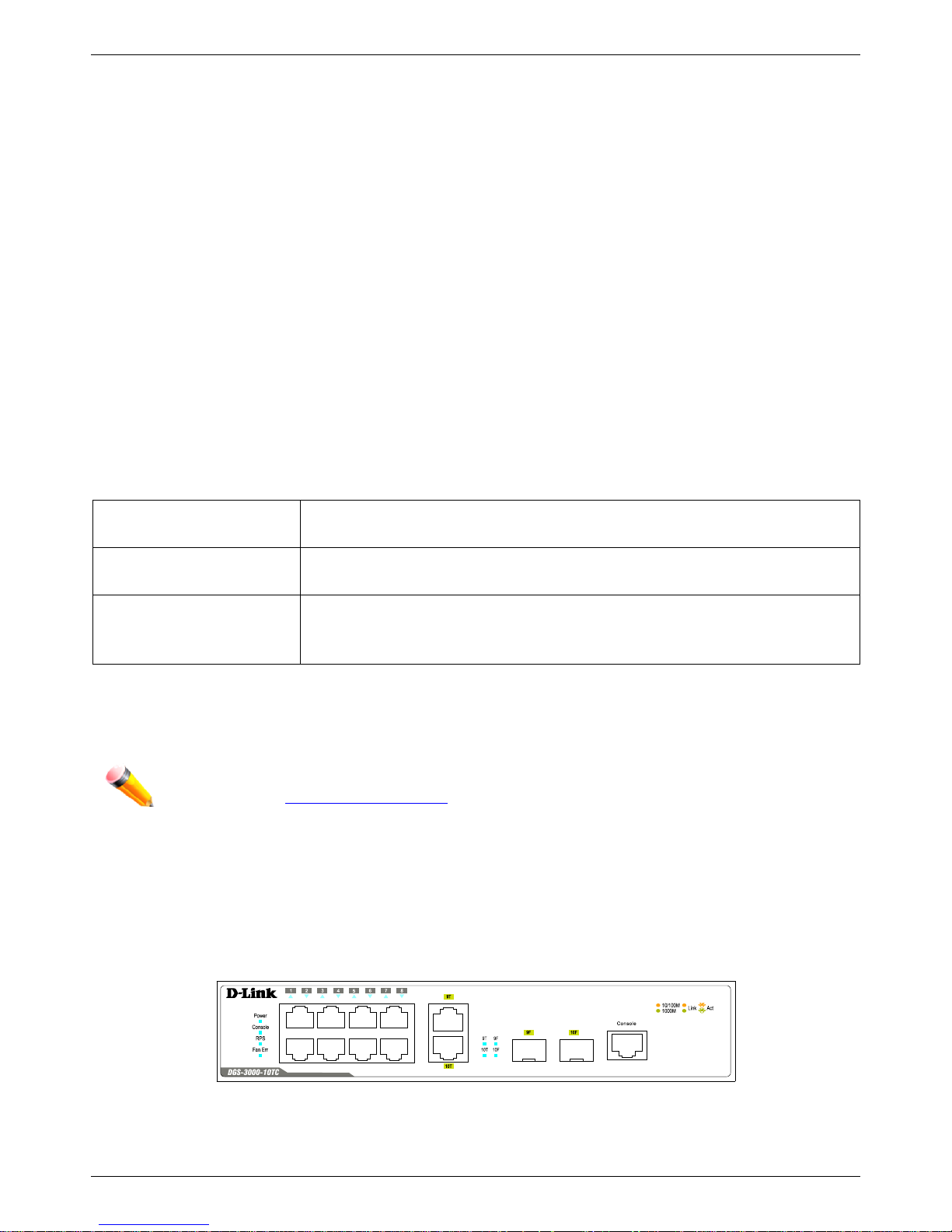
Front Panel Components
The front panel of the Switch consists of LED indicators for Power, Console, RPS, Fan Err, and for Link/Act for each
port on the Switch including SFP port LEDs. DGS-3000-26TC has an alarm port at the front panel.
Figure 1-1 Front panel view of the DGS-3000-10TC

DGS-3000 Series Layer 2 Managed Gigabit Ethernet Switch Hardware Installation Guide
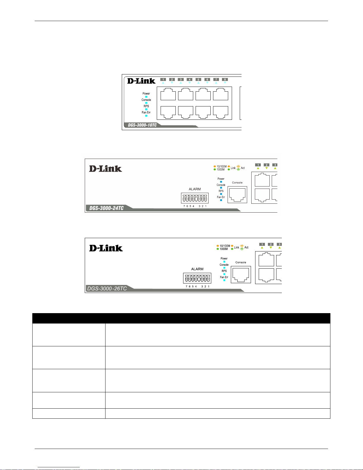
4
Figure 1-2 Front panel view of the DGS-3000-24TC
Figure 1-3 Front panel view of the DGS-3000-26TC
DGS-3000 Series Layer 2 Managed Gigabit Ethernet Switch Hardware Installation Guide
5
LED Indicators
The Switch front panel presents LED indicators for Power, Console, RPS, Fan Err, and Link/Act indicators for all ports
including the Gigabit Ethernet ports.
Figure 1-4 LED indicators for the DGS-3000-10TC
Figure 1-5 LED indicators for the DGS-3000-24TC
Figure 1-6 LED indicators for the DGS-3000-26TC
LED Description
Power
This LED lights green after powering the Switch on to indicate the ready state of the
device. The indicator is dark when the Switch is no longer receiving power (i.e. powered
off).
Console
This LED blinks green during the Power-On Self Test (POST). When the POST is
finished, the LED goes dark. The indicator lights steady green when a user is logged in
through the console port.
RPS
This LED lights green if the Redundant Power Supply (RPS) is connected, the RPS
switch is turned on. If the indicator is off, the RPS is not connected or the RPS switch is
turned off.
Fan Err
This LED blinks red when any of the fans has failed. No light indicates all fans are
working normally.
Link/Act LEDs
The Switch has LED indicators for Link and Activity.
DGS-3000 Series Layer 2 Managed Gigabit Ethernet Switch Hardware Installation Guide
6
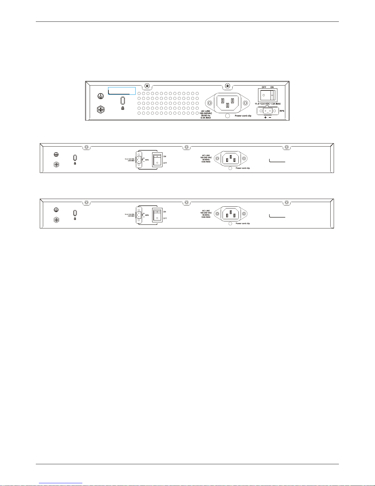
Rear Panel Description
The rear panel contains an AC power socket, an ON/OFF toggle switch, an outlet for an external redundant power
supply or a DC power supply, and security lock.
Figure 1-7 Rear panel view of the DGS-3000-10TC
Figure 1-8 Rear panel view of the DGS-3000-24TC
Figure 1-9 Rear panel view of the DGS-3000-26TC
The AC power socket is a standard three-pronged connector that supports the power cord. Plug-in the female
connector of the provided power cord into this socket, and the male side of the cord into a power outlet. The Switch
automatically adjusts the power setting to any supply voltage in the range from 100 to 240 VAC at 50 to 60 Hz. An
optional external Redundant Power Supply (DPS-200) can be plugged into the RPS outlet displayed above. When the
internal power fails, this optional external RPS will take over all the power immediately and automatically.
DGS-3000 Series Layer 2 Managed Gigabit Ethernet Switch Hardware Installation Guide
7
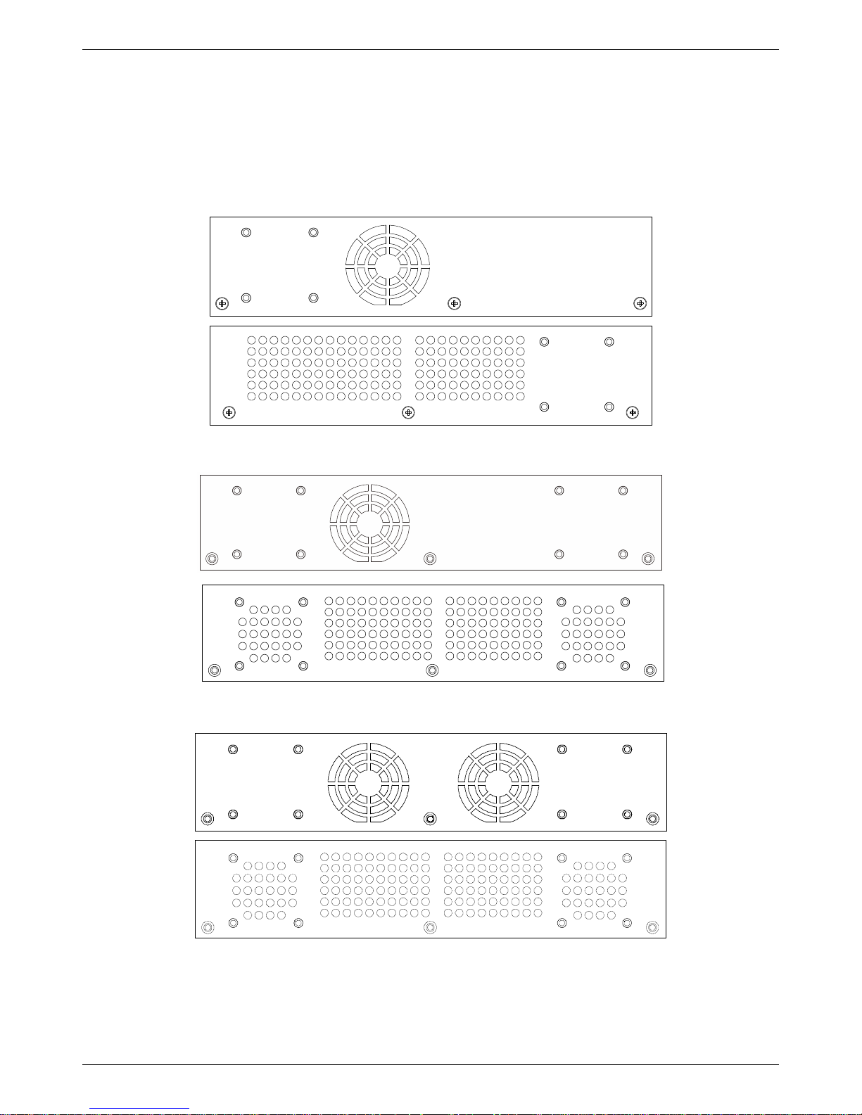
Side Panel Description
The system heat vents located on each side dissipate heat. Do not block these openings. Leave at least 6 inches of
space at the rear and sides of the Switch for proper ventilation. Be reminded that without proper heat dissipation and
air circulation, system components might overheat, which could lead to system failure or even severely damage
components.
Figure 1-10 Identical side panels of the DGS-3000-10TC
Figure 1-11 Identical side panels of the DGS-3000-24TC
Figure 1-12 Identical side panels of the DGS-3000-26TC

DGS-3000 Series Layer 2 Managed Gigabit Ethernet Switch Hardware Installation Guide
8
Chapter 2 Installation
Package Contents
Installation Guidelines
Power On (AC Power)
Alarm Connector (DGS-3000-24TC/26TC Only)
Installing Power Cord Clip
Installing SFP and SFP+ Ports
Connecting the DPS-2000 to the RPS Port
Installing the RPS into a Rack-mountChassis
Package Contents
Open the shipping carton of the Switch and carefully unpack its contents. The carton should contain the following
items:
• One DGS-3000 Series Switch
• One Quick Installation Guide
• AC power cord(s)
• One DC power source connector
• One RJ-45 to RS-232 console
• One set of Power Cord Clip
• One mounting kit (two brackets and screws)
• Four rubber feet with adhesive backing
• One CD kit for Web UI Reference Guide, CLI Reference Guide, and D-View module
If any item is missing or damaged, please contact your local D-Link reseller for replacement.
Installation Guidelines
Please follow these guidelines for setting up the Switch:
• Install the Switch on a sturdy, level surface that can support at least 13.9 lb. (6.3 kg) of weight. Do not place
heavy objects on the Switch.
• The power outlet should be within 1.82 meters (6 feet) of the Switch.
• Visually inspect the power cord and see that it is full y secur ed to the AC power p ort.
• Make sure that there is proper heat dissipation from and adequate ventilation around the Switch. Leave at
least 10 cm (4 inches) of space at the front and rear of the Switch for ventilation.
• Install the Switch in a fairly cool and dry place for the acceptable temperature and humidity operating ranges.
• Install the Switch in a site free from strong electromagnetic field generators (such as motors), vibration, dust,
and direct exposure to sunlight.
• When installing the Switch on a level surface, attach the rubber feet to the bottom of the device. The rubber
feet cushion the Switch, protect the casing from scratches and prevent it from scratching other surfaces.
DGS-3000 Series Layer 2 Managed Gigabit Ethernet Switch Hardware Installation Guide
9
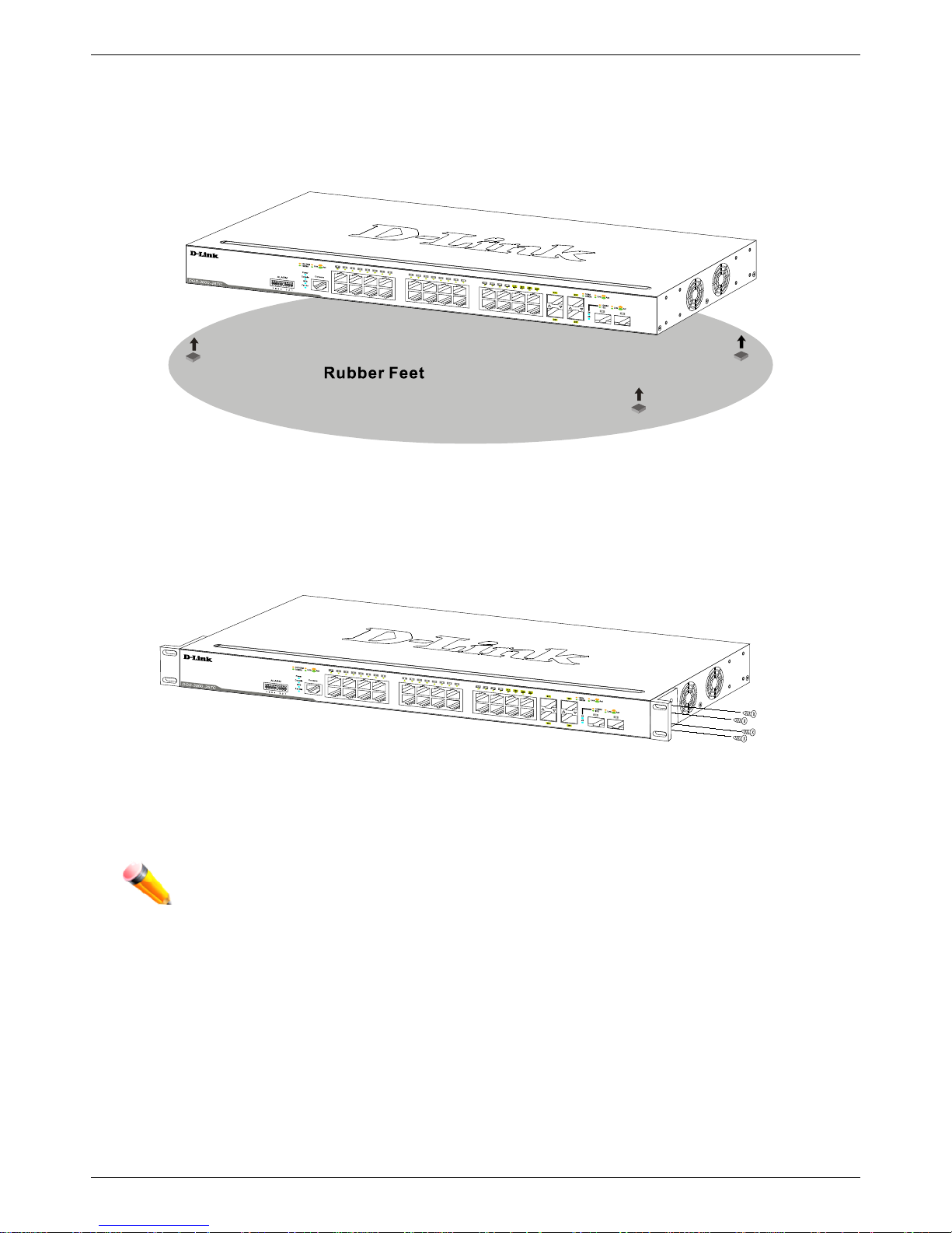
Installing the Switch without a Rack
First, attach the rubber feet included with the Switch if installing on a desktop or shelf. Attach these cushioning feet on
the bottom at each corner of the device. Allow enough ventilation space between the Switch and any other objects in
the vicinity.
Figure 2-1 Prepare the Switch for installation on a desktop or shelf
Attaching Brackets to a Switch for Rack Mounting
The Switch can be mounted in a standard 19" rack using the provided mounting brackets. Use the following diagrams
as a guide.
Figure 2-2 Fasten mounting brackets on the Switch
Fasten the mounting brackets to the Switch using the screws provided. With the brackets attached securely, the
Switch can be mounted in a standard rack, as shown below.
NOTE: Please review the I nstal lat ion Guidelines above before installing the Switch in a rack. Make
sure there is adequate space around the Switch to allow for proper air flow, ventilation, and
cooling.
DGS-3000 Series Layer 2 Managed Gigabit Ethernet Switch Hardware Installation Guide
10
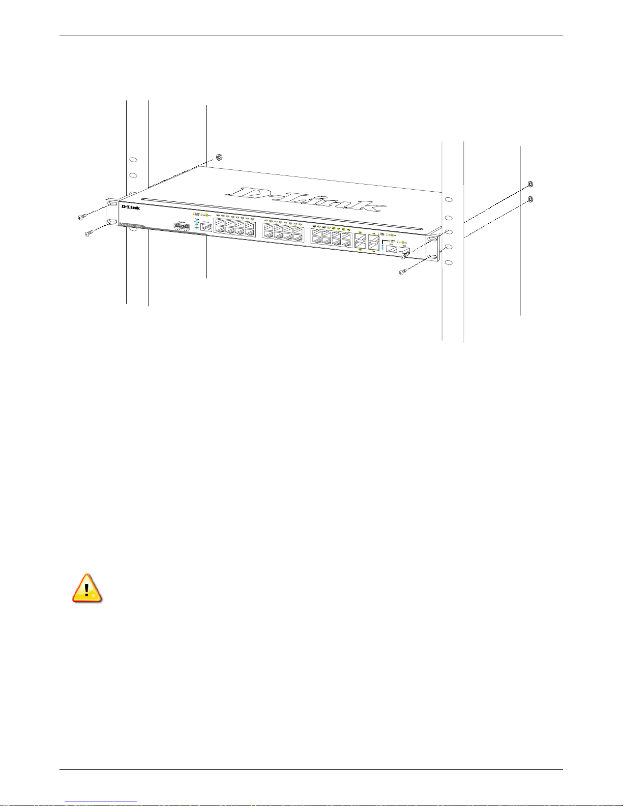
Mounting the Switch in a Standard 19" Rack
Figure 2-3 Installing the Switch in a rack
Power On (AC Power)
1. Plug one end of the AC power cord into the power socket of the Switch and the other end into the local power
source outlet.
2. After powering on the Switch, the LED indicators will momentarily blink green. This blinking of the LED
indicators represents a reset of the system.
Power Failure (AC Power)
For AC power supply units, as a precaution, in the event of a power failure, unplug the Switch. When power has
resumed, plug the Switch back in.
CAUTION: Installing systems in a rack without the front and side stabilizers installed could cause the
rack to tip over, potentially resulting in bodily injury under certain circumstances. Therefore, always
install the stabilizers before installing components in the rack. After installing components in a rack, do
not pull more than one component out of the rack on its slide assemblies at one time. The weight of
more than one extended component could cause the rack to tip over and may result in injury.
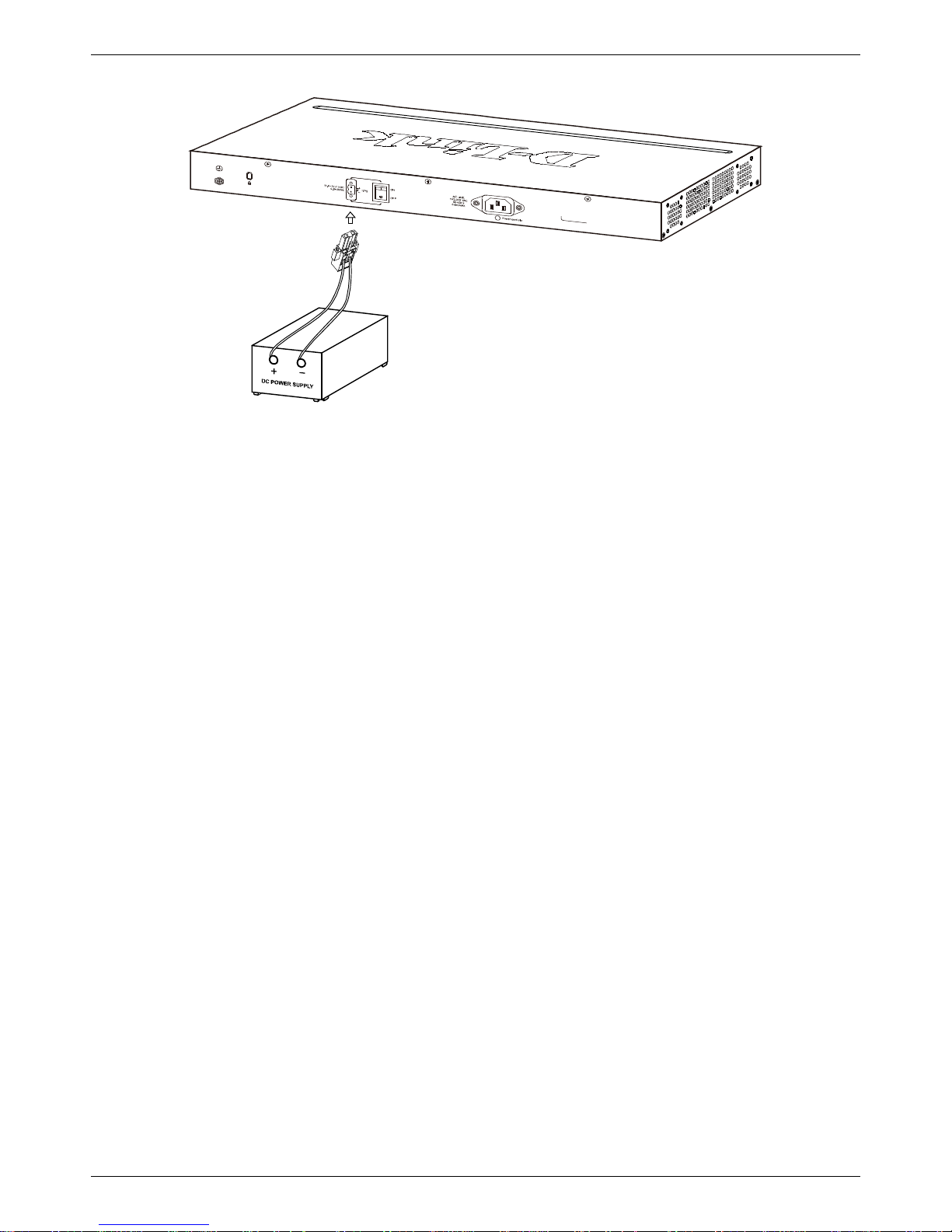
Connecting a DC Power Supply
The Switch provides a DC power source connector to connect to any DC power source. The DC power source must
meet the following requirements:
• The DC power source's output voltage must be between 11.4V and 12.6V.
• The DC power source's output current rate must be higher or equal to 2.5A.
• Voltage protection must be apllied when the voltage is higher or equal to 15V.
• Current protection must be apllied when the current is higher or equal to 6A.
DGS-3000 Series Layer 2 Managed Gigabit Ethernet Switch Hardware Installation Guide
11
Figure 2-4 Connecting a DC power source to the Switch
1. Make sure that the ON/OFF toggle switch on the rear panel of the Switch is turned off.
2. Connect one end of the DC power cords supplied to a DC power source that will be activated when the AC
power is not working. Make sure that connection polarity (positive and negative) is correct at both sides before
using this feature to avoid any damaged.
3. Connect the other end of the DC power cords to the DC power source connector.
4. Connect the DC power source connector to the switch.
5. Turn the ON/OFF toggle switch on.
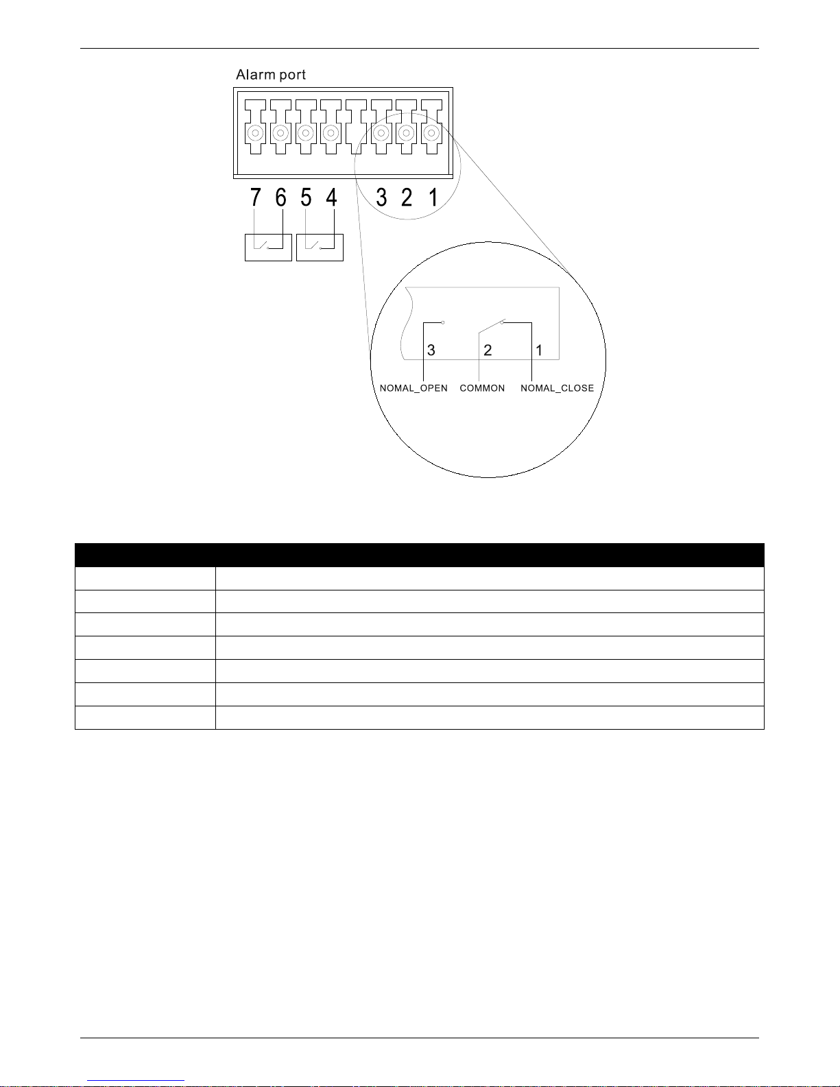
Alarm Connector (DGS-3000-24TC/26TC Only)
The alarm connector can be used to use external devices when triggered events occur.
DGS-3000 Series Layer 2 Managed Gigabit Ethernet Switch Hardware Installation Guide
12
Figure 2-5 Alarm Connector
The following table describes the alarm connector port pin layout.
Contact Description
1
Output. Normal Closed Pin. (42VAC or 60VDC)
2
Output. Common Pin. (42VAC or 60VDC)
3
Output. Normal Open Pin. (42VAC or 60VDC)
4
Input 2
5
Input 2
6
Input 1
7
Input 1
Connect the alarm input pins to alarm output terminals on other pieces of equipment.
Connect the alarm output pins to alarm input terminals on other pieces of equipment.
DGS-3000 Series Layer 2 Managed Gigabit Ethernet Switch Hardware Installation Guide
13
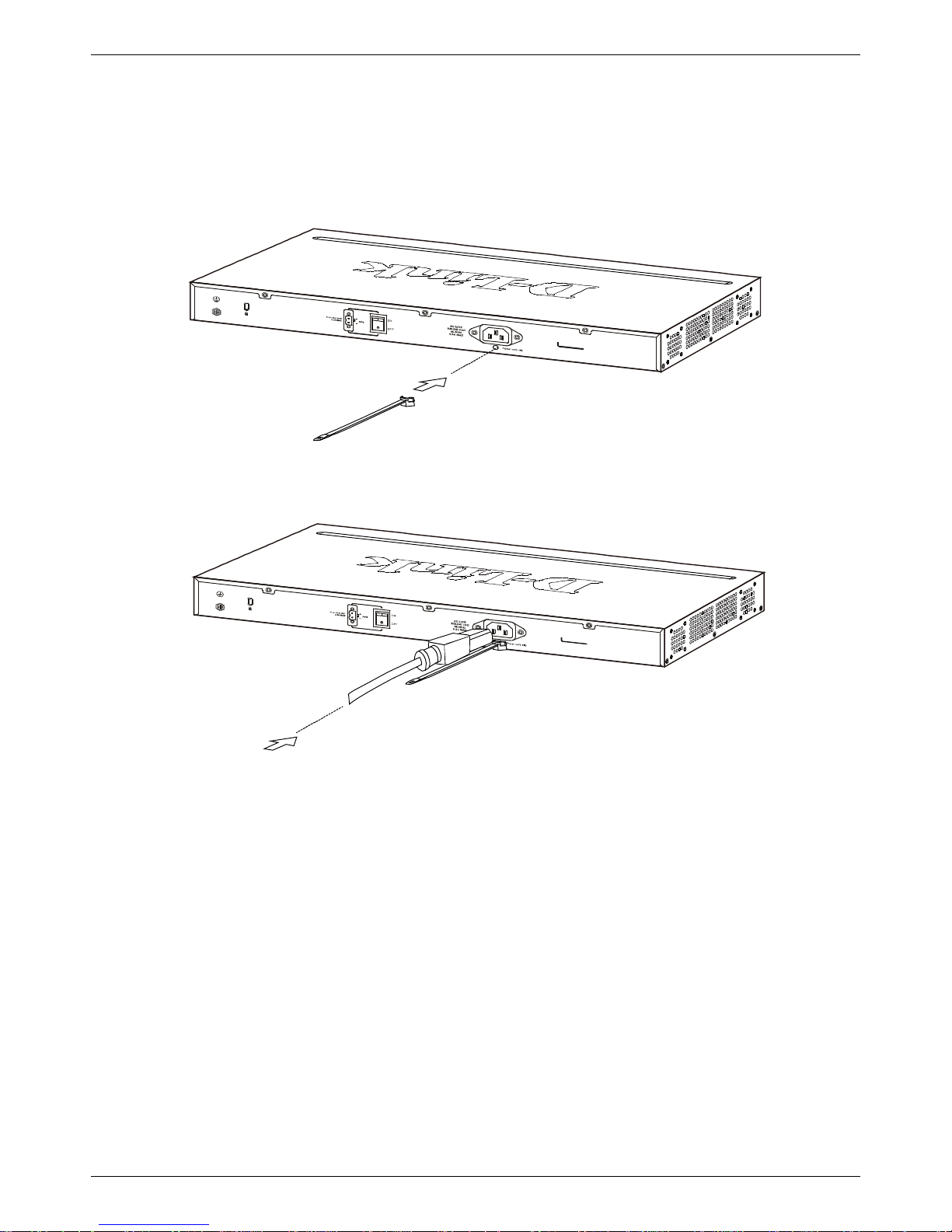
Installing Power Cord Clip
To prevent accidental removal of the AC power cord, it is recommended to install the power cord clip together with the
power cord.
1. With the rough side facing down, insert the Tie Wrap into the hole below the power socket.
Figure 2-6 Insert Tie Wrap to the Switch
2. Plug the AC power cord into the power socket of the Switch.
Figure 2-7 Connect the power cord to the Switch
 Loading...