

Page 1
1
Page 2

DGS-1510 Series Gigabit Ethernet SmartPro Switch Web UI Reference Guide
Information in this document is subject to change without notice. Reproduction of this document in any manner,
without the written permission of the D-Link Corporation, is strictly forbidden.
Trademarks used in this text: D-Link and the D-Link logo are trademarks of the D-Link Corporation; Microsoft and
Windows are registered trademarks of the Microsoft Corporation.
Other trademarks and trade names may be used in this document to refer to either as the entities claiming the
marks and the names or their products. D-Link Corporation disclaims any proprietary interest in trademarks and
trade names other than its own.
© 2015 D-Link Corporation. All rights reserved.
October 2015
ii
Page 3

DGS-1510 Series Gigabit Ethernet SmartPro Switch Web UI Reference Guide
Table of Contents
1. Introduction ............................................................................................................................................................. 1
Audience ...................................................................................................................................................................... 1
Other Documentation ................................................................................................................................................... 1
Conventions ................................................................................................................................................................. 1
Notes, Notices, and Cautions ...................................................................................................................................... 1
2. Web-based Switch Configuration .......................................................................................................................... 3
Management Options ................................................................................................................................................... 3
Connecting using the Web User Interface ................................................................................................................... 3
Logging onto the Web Manager .................................................................................................................................. 3
Smart Wizard ............................................................................................................................................................... 4
Web User Interface (Web UI) ....................................................................................................................................... 7
Areas of the User Interface ..................................................................................................................................... 7
3. System ...................................................................................................................................................................... 9
Device Information ....................................................................................................................................................... 9
System Information Settings ........................................................................................................................................ 9
Peripheral Settings ..................................................................................................................................................... 10
Port Configuration ...................................................................................................................................................... 11
Port Settings ......................................................................................................................................................... 11
Port Status ............................................................................................................................................................ 12
Port Auto Negotiation ............................................................................................................................................ 13
Error Disable Settings ........................................................................................................................................... 14
Jumbo Frame ........................................................................................................................................................ 15
PoE (DGS-1510-28P and DGS-1510-28XMP Only) ................................................................................................. 15
PoE System .......................................................................................................................................................... 16
PoE Status ............................................................................................................................................................ 16
PoE Configuration ................................................................................................................................................. 17
PoE Statistics ........................................................................................................................................................ 18
PoE Measurement ................................................................................................................................................ 19
PoE LLDP Classification ....................................................................................................................................... 20
System Log ................................................................................................................................................................ 21
System Log Settings ............................................................................................................................................. 21
System Log Discriminator Settings ....................................................................................................................... 22
System Log Server Settings ................................................................................................................................. 23
System Log ........................................................................................................................................................... 24
System Attack Log ................................................................................................................................................ 24
Time and SNTP ......................................................................................................................................................... 25
Clock Settings ....................................................................................................................................................... 25
Time Zone Settings ............................................................................................................................................... 25
SNTP Settings ...................................................................................................................................................... 27
Time Range................................................................................................................................................................ 28
4. Management .......................................................................................................................................................... 29
User Account Settings ............................................................................................................................................... 29
Password Encryption ................................................................................................................................................. 30
Login Method ............................................................................................................................................................. 31
SNMP ......................................................................................................................................................................... 32
SNMP Global Settings .......................................................................................................................................... 33
SNMP Linkchange Trap Settings ......................................................................................................................... 34
SNMP View Table Settings ................................................................................................................................... 35
iii
Page 4

DGS-1510 Series Gigabit Ethernet SmartPro Switch Web UI Reference Guide
SNMP Community Table Settings ........................................................................................................................ 36
SNMP Group Table Settings .............................................................................................................................. 37
SNMP Engine ID Local Settings ........................................................................................................................... 38
SNMP User Table Settings ................................................................................................................................... 39
SNMP Host Table Settings ................................................................................................................................... 40
RMON ........................................................................................................................................................................ 41
RMON Global Settings ......................................................................................................................................... 41
RMON Statistics Settings ..................................................................................................................................... 41
RMON History Settings ......................................................................................................................................... 42
RMON Alarm Settings .......................................................................................................................................... 43
RMON Event Settings ........................................................................................................................................... 44
Telnet/Web ................................................................................................................................................................. 45
Session Timeout ........................................................................................................................................................ 46
DHCP ......................................................................................................................................................................... 47
Service DHCP ....................................................................................................................................................... 47
DHCP Class Settings ............................................................................................................................................ 47
DHCP Relay ......................................................................................................................................................... 48
DHCPv6 Relay ...................................................................................................................................................... 54
DHCP Auto Configuration ..................................................................................................................................... 55
DNS ............................................................................................................................................................................ 55
DNS Global Settings ............................................................................................................................................. 56
DNS Name Server Settings .................................................................................................................................. 57
DNS Host Settings ................................................................................................................................................ 57
NTP ............................................................................................................................................................................ 58
NTP Global Settings ............................................................................................................................................. 58
NTP Server Settings ............................................................................................................................................. 59
NTP Peer Settings ................................................................................................................................................ 59
NTP Access Group Settings ................................................................................................................................. 60
NTP Key Settings ................................................................................................................................................. 61
NTP Interface Settings .......................................................................................................................................... 62
NTP Associations ................................................................................................................................................. 62
NTP Status............................................................................................................................................................ 63
IP Source Interface .................................................................................................................................................... 64
File System ................................................................................................................................................................ 64
Physical Stacking ....................................................................................................................................................... 66
Virtual Stacking (SIM) ................................................................................................................................................ 70
Single IP Settings ................................................................................................................................................. 72
Topology ............................................................................................................................................................... 73
Firmware Upgrade ................................................................................................................................................ 80
Configuration File Backup/Restore ....................................................................................................................... 80
Upload Log File ..................................................................................................................................................... 81
D-Link Discovery Protocol .......................................................................................................................................... 81
5. Layer 2 Features .................................................................................................................................................... 83
FDB ............................................................................................................................................................................ 83
Static FDB ............................................................................................................................................................. 83
MAC Address Table Settings................................................................................................................................ 84
MAC Address Table .............................................................................................................................................. 85
MAC Notification ................................................................................................................................................... 86
VLAN .......................................................................................................................................................................... 87
802.1Q VLAN ........................................................................................................................................................ 87
802.1v Protocol VLAN .......................................................................................................................................... 88
GVRP .................................................................................................................................................................... 89
iv
Page 5

DGS-1510 Series Gigabit Ethernet SmartPro Switch Web UI Reference Guide
Asymmetric VLAN ................................................................................................................................................. 93
MAC VLAN............................................................................................................................................................ 94
VLAN Interface ..................................................................................................................................................... 94
Auto Surveillance VLAN ....................................................................................................................................... 97
Voice VLAN .......................................................................................................................................................... 99
Spanning Tree ......................................................................................................................................................... 102
STP Global Settings ........................................................................................................................................... 105
STP Port Settings ............................................................................................................................................... 106
MST Configuration Identification ........................................................................................................................ 108
STP Instance ...................................................................................................................................................... 109
MSTP Port Information ....................................................................................................................................... 109
ERPS (G.8032) ........................................................................................................................................................ 110
ERPS .................................................................................................................................................................. 110
ERPS Profile ....................................................................................................................................................... 113
Loopback Detection ................................................................................................................................................. 114
Link Aggregation ...................................................................................................................................................... 115
L2 Multicast Control ................................................................................................................................................. 118
IGMP Snooping .................................................................................................................................................. 118
MLD Snooping .................................................................................................................................................... 123
Multicast Filtering ................................................................................................................................................ 129
LLDP ........................................................................................................................................................................ 130
LLDP Global Settings ......................................................................................................................................... 130
LLDP Port Settings ............................................................................................................................................. 132
LLDP Management Address List ........................................................................................................................ 133
LLDP Basic TLVs Settings .................................................................................................................................. 133
LLDP Dot1 TLVs Settings ................................................................................................................................... 134
LLDP Dot3 TLVs Settings ................................................................................................................................... 135
LLDP-MED Port Settings .................................................................................................................................... 136
LLDP Statistics Information ................................................................................................................................ 137
LLDP Local Port Information............................................................................................................................... 138
LLDP Neighbor Port Information ........................................................................................................................ 140
6. Layer 3 Features .................................................................................................................................................. 141
ARP .......................................................................................................................................................................... 142
ARP Aging Time ................................................................................................................................................. 142
Static ARP........................................................................................................................................................... 143
Proxy ARP .......................................................................................................................................................... 143
ARP Table........................................................................................................................................................... 144
Gratuitous ARP ........................................................................................................................................................ 144
UDP Helper .............................................................................................................................................................. 145
IP Forward Protocol ............................................................................................................................................ 145
IP Helper Address ............................................................................................................................................... 146
IPv4 Interface ........................................................................................................................................................... 147
IPv4 Static/Default Route ......................................................................................................................................... 149
IPv4 Route Table ..................................................................................................................................................... 149
IPv6 Interface ........................................................................................................................................................... 150
IPv6 Neighbor .......................................................................................................................................................... 152
IPv6 Static/Default Route ......................................................................................................................................... 153
IPv6 Route Table ..................................................................................................................................................... 153
7. Quality of Service (QoS) ..................................................................................................................................... 155
Basic Settings .......................................................................................................................................................... 155
Port Default CoS ................................................................................................................................................. 155
v
Page 6

DGS-1510 Series Gigabit Ethernet SmartPro Switch Web UI Reference Guide
Port Scheduler Method ....................................................................................................................................... 155
Queue Settings ................................................................................................................................................... 157
CoS to Queue Mapping ...................................................................................................................................... 157
Port Rate Limiting ............................................................................................................................................... 158
Queue Rate Limiting ........................................................................................................................................... 159
Advanced Settings ................................................................................................................................................... 160
DSCP Mutation Map ........................................................................................................................................... 160
Port Trust State and Mutation Binding ................................................................................................................ 161
DSCP CoS Mapping ........................................................................................................................................... 162
CoS Color Mapping ............................................................................................................................................ 163
DSCP Color Mapping ......................................................................................................................................... 163
Class Map ........................................................................................................................................................... 164
Aggregate Policer ............................................................................................................................................... 166
Policy Map .......................................................................................................................................................... 169
Policy Binding ..................................................................................................................................................... 171
8. Access Control List (ACL) .................................................................................................................................. 173
ACL Configuration Wizard ....................................................................................................................................... 173
ACL Access List ....................................................................................................................................................... 203
Standard IP ACL ................................................................................................................................................. 204
Extended IP ACL ................................................................................................................................................ 207
Standard IPv6 ACL ............................................................................................................................................. 224
Extended IPv6 ACL ............................................................................................................................................ 228
Extended MAC ACL ............................................................................................................................................ 240
Extended Expert ACL ......................................................................................................................................... 243
ACL Interface Access Group ................................................................................................................................... 269
ACL VLAN Access Map ........................................................................................................................................... 269
ACL VLAN Filter ....................................................................................................................................................... 271
9. Security ................................................................................................................................................................ 272
Port Security............................................................................................................................................................. 272
Port Security Global Settings .............................................................................................................................. 272
Port Security Port Settings .................................................................................................................................. 273
Port Security Address Entries ............................................................................................................................. 274
802.1X ...................................................................................................................................................................... 275
802.1X Global Settings ....................................................................................................................................... 279
802.1X Port Settings ........................................................................................................................................... 279
Authentication Session Information .................................................................................................................... 281
Authenticator Statistics ....................................................................................................................................... 281
Authenticator Session Statistics ......................................................................................................................... 282
Authenticator Diagnostics ................................................................................................................................... 282
AAA .......................................................................................................................................................................... 283
AAA Global Settings ........................................................................................................................................... 283
Application Authentication Settings .................................................................................................................... 283
Application Accounting Settings ......................................................................................................................... 284
Authentication Settings ....................................................................................................................................... 284
Accounting Settings ............................................................................................................................................ 286
RADIUS .................................................................................................................................................................... 288
RADIUS Global Settings ..................................................................................................................................... 288
RADIUS Server Settings ..................................................................................................................................... 289
RADIUS Group Server Settings ......................................................................................................................... 289
RADIUS Statistic ................................................................................................................................................. 290
TACACS ................................................................................................................................................................... 291
vi
Page 7

DGS-1510 Series Gigabit Ethernet SmartPro Switch Web UI Reference Guide
TACACS Server Settings .................................................................................................................................... 291
TACACS Group Server Settings ........................................................................................................................ 292
TACACS Statistic ................................................................................................................................................ 293
IMPB ........................................................................................................................................................................ 293
IPv4 ..................................................................................................................................................................... 293
IPv6 ..................................................................................................................................................................... 306
DHCP Server Screening .......................................................................................................................................... 311
DHCP Server Screening Global Settings ........................................................................................................... 312
DHCP Server Screening Port Settings ............................................................................................................... 313
ARP Spoofing Prevention ........................................................................................................................................ 313
BPDU Attack Protection ........................................................................................................................................... 314
MAC Authentication ................................................................................................................................................. 315
Web-based Access Control ..................................................................................................................................... 317
Web Authentication ............................................................................................................................................. 319
WAC Port Settings .............................................................................................................................................. 319
WAC Customize Page ........................................................................................................................................ 320
Japanese Web-based Access Control ..................................................................................................................... 321
JWAC Global Settings ........................................................................................................................................ 321
JWAC Port Settings ............................................................................................................................................ 324
JWAC Customize Page Language ..................................................................................................................... 324
JWAC Customize Page ...................................................................................................................................... 325
Network Access Authentication ............................................................................................................................... 326
Guest VLAN ........................................................................................................................................................ 326
Network Access Authentication Global Settings................................................................................................. 327
Network Access Authentication Port Settings .................................................................................................... 328
Network Access Authentication Sessions Information ....................................................................................... 330
Safeguard Engine .................................................................................................................................................... 331
Safeguard Engine Settings ................................................................................................................................. 332
CPU Protect Counters ........................................................................................................................................ 333
CPU Protect Sub-Interface ................................................................................................................................. 333
CPU Protect Type ............................................................................................................................................... 334
Trusted Host............................................................................................................................................................. 334
Traffic Segmentation Settings .................................................................................................................................. 335
Storm Control ........................................................................................................................................................... 336
DoS Attack Prevention Settings ............................................................................................................................... 338
SSH .......................................................................................................................................................................... 339
SSH Global Settings ........................................................................................................................................... 340
Host Key ............................................................................................................................................................. 340
SSH Server Connection ...................................................................................................................................... 341
SSH User Settings .............................................................................................................................................. 341
SSL .......................................................................................................................................................................... 342
SSL Global Settings ............................................................................................................................................ 343
Crypto PKI Trustpoint ......................................................................................................................................... 343
SSL Service Policy ............................................................................................................................................. 344
10. OAM ...................................................................................................................................................................... 346
Cable Diagnostics .................................................................................................................................................... 346
DDM ......................................................................................................................................................................... 346
DDM Settings ...................................................................................................................................................... 346
DDM Temperature Threshold Settings ............................................................................................................... 347
DDM Voltage Threshold Settings ....................................................................................................................... 348
DDM Bias Current Threshold Settings ............................................................................................................... 348
DDM TX Power Threshold Settings .................................................................................................................... 349
vii
Page 8

DGS-1510 Series Gigabit Ethernet SmartPro Switch Web UI Reference Guide
DDM RX Power Threshold Settings ................................................................................................................... 350
DDM Status Table .............................................................................................................................................. 351
11. Monitoring ............................................................................................................................................................ 352
Utilization .................................................................................................................................................................. 352
Port Utilization ..................................................................................................................................................... 352
Statistics ................................................................................................................................................................... 353
Port ..................................................................................................................................................................... 353
Port Counters ...................................................................................................................................................... 354
Counters ............................................................................................................................................................. 356
Mirror Settings .......................................................................................................................................................... 357
sFlow ........................................................................................................................................................................ 359
sFlow Agent Information ..................................................................................................................................... 359
sFlow Receiver Settings ..................................................................................................................................... 359
sFlow Sampler Settings ...................................................................................................................................... 360
sFlow Poller Settings .......................................................................................................................................... 361
Device Environment ................................................................................................................................................. 362
12. Green .................................................................................................................................................................... 363
Power Saving ........................................................................................................................................................... 363
EEE .......................................................................................................................................................................... 364
13. Save and Tools .................................................................................................................................................... 366
Save Configuration .................................................................................................................................................. 366
Firmware Upgrade & Backup ................................................................................................................................... 366
Firmware Upgrade from HTTP ........................................................................................................................... 366
Firmware Upgrade from TFTP ............................................................................................................................ 367
Firmware Backup to HTTP ................................................................................................................................. 367
Firmware Backup to TFTP .................................................................................................................................. 368
Configuration Restore & Backup ............................................................................................................................. 368
Configuration Restore from HTTP ...................................................................................................................... 368
Configuration Restore from TFTP ...................................................................................................................... 369
Configuration Backup to HTTP ........................................................................................................................... 370
Configuration Backup to TFTP ........................................................................................................................... 370
Log Backup .............................................................................................................................................................. 371
Log Backup to HTTP .......................................................................................................................................... 371
Log Backup to TFTP ........................................................................................................................................... 371
Ping .......................................................................................................................................................................... 372
Trace Route ............................................................................................................................................................. 374
Language Management ........................................................................................................................................... 375
Reset ........................................................................................................................................................................ 376
Reboot System ........................................................................................................................................................ 376
Appendix A - System Log Entries ............................................................................................................................. 378
Appendix B - Trap Entries .......................................................................................................................................... 403
Appendix C - RADIUS Attributes Assignment ......................................................................................................... 413
Appendix D - IETF RADIUS Attributes Support ....................................................................................................... 416
Appendix E - ERPS Information................................................................................................................................. 418
viii
Page 9

DGS-1510 Series Gigabit Ethernet SmartPro Switch Web UI Reference Guide
Convention
Description
Boldface Font
Indicates a button, a toolbar icon, menu, or menu item. For
example: Open the File menu and choose Cancel. Used for
emphasis. May also indicate system messages or prompts
appearing on screen. For example: You have mail. Bold font is
also used to represent filenames, program names and commands.
For example: use the copy command.
Initial capital letter
Indicates a window name. Names of keys on the keyboard have
initial capitals. For example: Click Enter.
Menu Name > Menu Option
Indicates the menu structure. Device > Port > Port Properties
means the Port Properties menu option under the Port menu
option that is located under the Device menu.
Blue Courier Font
This convention is used to represent an example of a screen
console display including example entries of CLI command input
with the corresponding output.
NOTE: A note indicates important information that helps you make better use of your
device.
NOTICE: A notice indicates either potential damage to hardware or loss of data and tells
you how to avoid the problem.
1. Introduction
This manual’s command descriptions are based on the software release 1.30. The commands listed
here are the subset of commands that are supported by the DGS-1510 Series SmartPro switch.
Audience
This reference manual is intended for network administrators and other IT networking professionals
responsible for managing the switch by using the Web User Interface (Web UI). The Web UI is the
secondary management interface to the DGS-1510 Series switch, which will be generally be referred
to simply as “the Switch” within this manual. This manual is written in a way that assumes that you
already have the experience and knowledge of Ethernet and modern networking principles for Local
Area Networks.
Other Documentation
The documents below are a further source of information in regards to configuring and
troubleshooting the switch. All the documents are available either from the CD, bundled with this
switch, or from the D-Link website. Other documents related to this switch are:
DGS-1510 Series Gigabit Ethernet SmartPro Switch Hardware Installation Guide
DGS-1510 Series Gigabit Ethernet SmartPro Switch CLI Reference Guide
Conventions
Notes, Notices, and Cautions
Below are examples of the three types of indicators used in this manual. When administering your
switch using the information in this document, you should pay special attention to these indicators.
Each example below provides an explanatory remark regarding each type of indicator.
1
Page 10

DGS-1510 Series Gigabit Ethernet SmartPro Switch Web UI Reference Guide
CAUTION: A caution indicates a potential for property damage, personal injury, or death.
2
Page 11

DGS-1510 Series Gigabit Ethernet SmartPro Switch Web UI Reference Guide
NOTE: The Command Line Interface (CLI) provides the functionality of managing,
configuring, and monitoring all of the software features that are available on the Switch.
NOTE: The default IP address of this switch is 10.90.90.90, with a subnet mask of
255.0.0.0.
2. Web-based Switch Configuration
Management Options
Connecting using the Web User Interface
Logging onto the Web Manager
Smart Wizard
Web User Interface (Web UI)
Management Options
The Switch provides multiple access platforms that can be used to configure, manage and monitor
networking features available on the Switch. Currently there are three management platforms
available and they are described below.
The Command Line Interface (CLI) through the RJ45 Console port or remote Telnet
The Switch can be managed, out-of-band, by using the console port on the front panel of the Switch.
Alternatively, the Switch can also be managed, in-band, by using a Telnet connection to any of the
LAN ports on the Switch. The command line interface provides complete access to all switch
management features.
SNMP-based Management
The Switch can be managed with an SNMP-compatible console program. The Switch supports SNMP
version 1.0, version 2.0 and version 3.0. The SNMP agent decodes the incoming SNMP messages
and responds to requests with MIB objects stored in the database. The SNMP agent updates the MIB
objects to generate statistics and counters.
Web-based Management Interface
After successfully installing the Switch, the user can configure the Switch, monitor the LED panel, and
display statistics graphically using a Web browser, such as Microsoft® Internet Explorer, Mozilla
Firefox, Safari, or Google Chrome.
Connecting using the Web User Interface
Most software functions of the DGS-1510 Series switches can be managed, configured and monitored
via the embedded web-based (HTML) interface. Manage the Switch from remote stations anywhere
on the network through a standard web browser. The web browser acts as a universal access tool
and can communicate directly with the Switch using the HTTP or HTTPS protocol.
Logging onto the Web Manager
To access the Web User Interface, simply open a standard web browser on the management PC and
enter the Switch’s default IP address into the address bar of the browser and press the Enter key.
3
Page 12
DGS-1510 Series Gigabit Ethernet SmartPro Switch Web UI Reference Guide
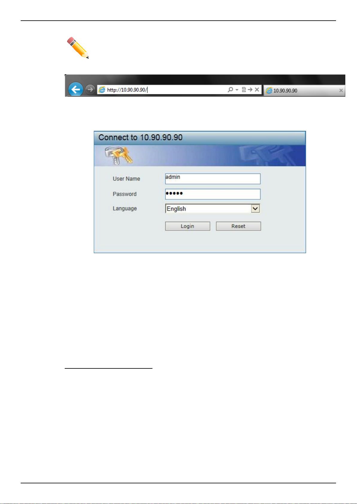
NOTE: The default username and password is admin.
Figure 2-1 Displays entering the IP address in Internet Explorer
This will open the user authentication window, as seen below.
Enter the User Name and Password in the corresponding fields and click Login. The default
username is admin and the default password is admin. This will open the Web-based user interface.
The Switch’s management features available in the web-based manager are explained below.
Smart Wizard
After a successfully connecting to the Web User Interface for the first time, the Smart Wizard
embedded Web utility will be launched. This wizard will guide the user through basic configuration
steps that is essential for first time connection to the Switch.
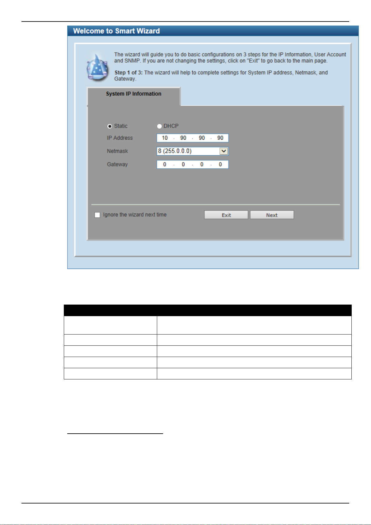
Step 1 – System IP Information
In this window, the user can configure the IP address assignment method, the static IP address,
Netmask and Gateway address.
Figure 2-2 User Authentication window
4
Page 13
DGS-1510 Series Gigabit Ethernet SmartPro Switch Web UI Reference Guide
Parameter
Description
Static
Select this option to manually configure and use IP address settings
on this switch.
DHCP
Select this option to obtain IP address settings from a DHCP server.
IP Address
Enter the IP address of the Switch here.
Netmask
Select the Netmask option here.
Gateway
Enter the default gateway IP address here.
Figure 2-3 System IP Information window
The fields that can be configured are described below:
Tick the Ignore the wizard next time option to skip the Smart Wizard on the next login.
Click the Exit button to discard the changes made, exit the Smart Wizard, and continue to the Web UI.
Click the Next button to accept the changes made and continue to the next step.
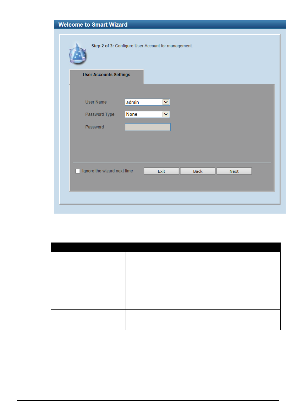
Step 2 – User Accounts Settings
In this window, the user can configure the user account settings. This step can only be modified by a
user account with the privilege level of 15.
5
Page 14
DGS-1510 Series Gigabit Ethernet SmartPro Switch Web UI Reference Guide
Parameter
Description
User Name
Select the user name of the administrator level account with the
privilege level of 15.
Password Type
Select the password type here. Options to choose from are None,
Plain Text, Encrypted-SHA1 and Encrypted-MD5. When selecting
Encrypted-SHA1 or Encrypted-MD5, the password will not be
encrypted from the plain-text format to the encrypted format.
Instead, the encrypted password must be entered. To encrypt the
password from the plain-text format to the encrypted format, refer to
the Password Encryption window.
Password
After selecting Plain Text, Encrypted-SHA1 or Encrypted-MD5 as
the Password Type, this field will be available. Enter the password
for the user account here.
Figure 2-4 SNMP window
The fields that can be configured are described below:
Tick the Ignore the wizard next time option to skip the Smart Wizard on the next login.
Click the Exit button to discard the changes made, exit the Smart Wizard, and continue to the Web UI.
Click the Back button to discard the changes made and return to the previous step.
Click the Apply button to accept the changes made and continue to the Web UI.
6
Page 15
DGS-1510 Series Gigabit Ethernet SmartPro Switch Web UI Reference Guide
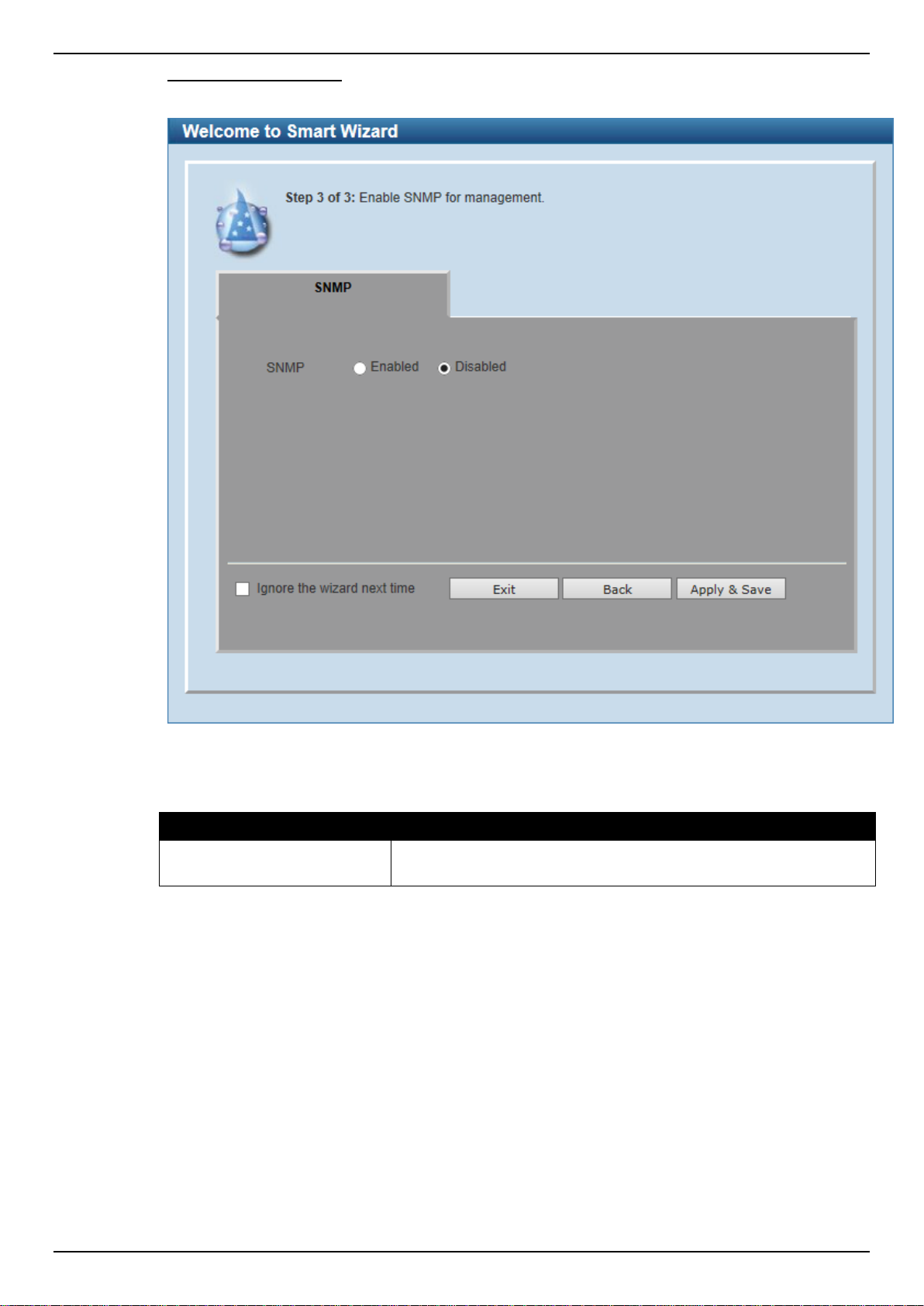
Parameter
Description
SNMP
Select the Enabled option to enable the SNMP function. Select the
Disabled option to disable the SNMP function.
Step 3 – SNMP Settings
In this window, the user can enable or disable the SNMP function.
Figure 2-5 SNMP window
The fields that can be configured are described below:
Tick the Ignore the wizard next time option to skip the Smart Wizard on the next login.
Click the Exit button to discard the changes made, exit the Smart Wizard, and continue to the Web UI.
Click the Back button to discard the changes made and return to the previous step.
Click the Apply & Save button to accept the changes made and continue to the Web UI.
Web User Interface (Web UI)
By clicking the Exit button in the Smart Wizard, you will enter the Web-based Management interface.
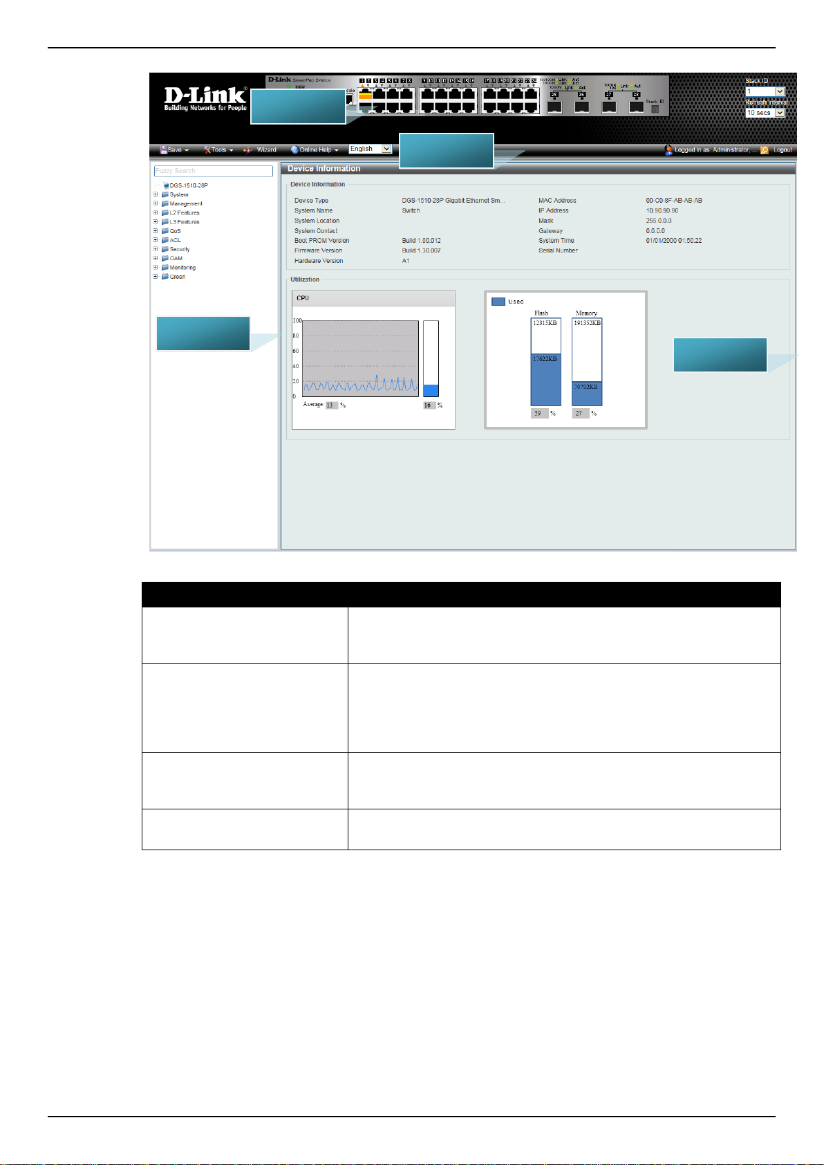
Areas of the User Interface
The figure below shows the user interface. Three distinct areas that divide the user interface, as
described in the table.
7
Page 16
DGS-1510 Series Gigabit Ethernet SmartPro Switch Web UI Reference Guide
Area Number
Description
AREA 1
Select the folder or window to display. Open folders and click the
hyperlinked window buttons and subfolders contained within them to
display windows.
AREA 2
Presents a graphical near real-time image of the front panel of the
Switch. This area displays the Switch's ports and expansion
modules and shows port activity, depending on the specified mode.
Some management functions, including port monitoring are
accessible here. Click the D-Link logo to go to the D-Link Website.
AREA 3
Presents Switch status based on user selection and the entry of
configuration data. In addition, hyperlinks are offered for many
Switch features to enable quick configuration.
AREA 4
Presents a toolbar used to access function like Save, Tools, the
Wizard, Online Help, and Language preference.
AREA 1
AREA 2
AREA 3
AREA 4
Figure 2-6 Main Web UI window
8
Page 17
DGS-1510 Series Gigabit Ethernet SmartPro Switch Web UI Reference Guide
3. System
Device Information
System Information Settings
Peripheral Settings
Port Configuration
PoE (DGS-1510-28P and DGS-1510-28XMP Only)
System Log
Time and SNTP
Time Range
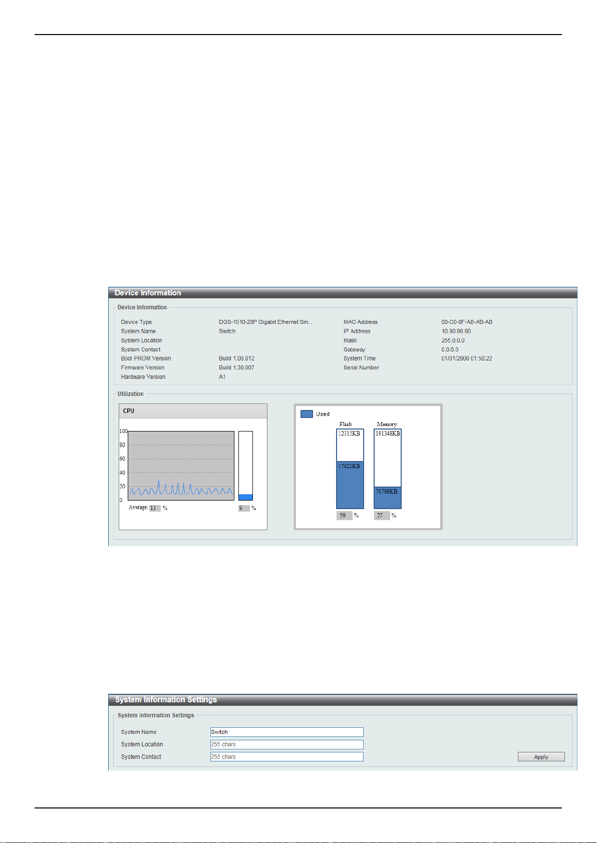
Device Information
In this window, the Device Information, CPU, and Used status are displayed. It appears automatically
when you log in the Switch. To return to the Device Information window after viewing other windows,
click the DGS-1510-28P link.
Figure 3-1 Device Information window
System Information Settings
The user can enter a System Name, System Location, and System Contact to aid in defining the
Switch.
To view the following window, click System > System Information Settings, as shown below:
Figure 3-2 System Information Settings window
9
Page 18
DGS-1510 Series Gigabit Ethernet SmartPro Switch Web UI Reference Guide
Parameter
Description
System Name
Enter a system name for the Switch, if so desired. This name will
identify it in the Switch network.
System Location
Enter the location of the Switch, if so desired. This string can be up
to 255 characters long.
System Contact
Enter a contact name for the Switch, if so desired. This string can
be up to 255 characters long.
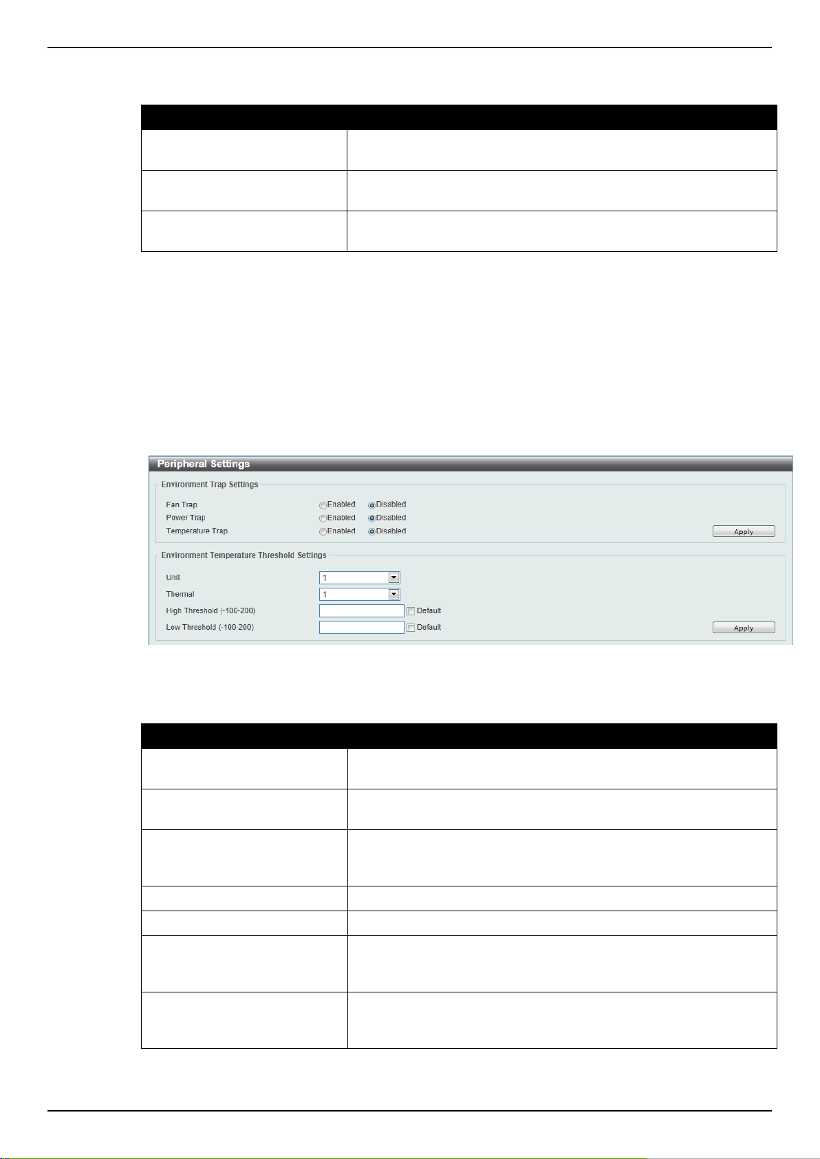
Parameter
Description
Fan Trap
Click to enable or disable the fan trap state for waning fan event
(fan failed or fan recover).
Power Trap
Click to enable or disable the power trap state for waning power
event (power failed or power recover).
Temperature Trap
Click to enable or disable the temperature trap state for waning
temperature event (temperature exceeds the thresholds or
temperature recover).
Unit
Select the switch unit that will be used for this configuration here.
Thermal
Select the thermal sensor ID.
High Threshold
Enter the high threshold value of the warning temperature setting.
The range is from -100 to 200 Celsius degree. Tick the Default
check box to return to the default value.
Low Threshold
Enter the low threshold value of the warning temperature setting.
The range is from -100 to 200 Celsius degree. Tick the Default
check box to return to the default value.
The fields that can be configured are described below:
Click the Apply button to accept the changes made.
Peripheral Settings
This window is used to configure the environment trap settings and environment temperature
threshold settings.
To view the following window, click System > Peripheral Settings, as shown below:
Figure 3-3 Peripheral Settings window
The fields that can be configured are described below:
Click the Apply button to accept the changes made.
10
Page 19
DGS-1510 Series Gigabit Ethernet SmartPro Switch Web UI Reference Guide
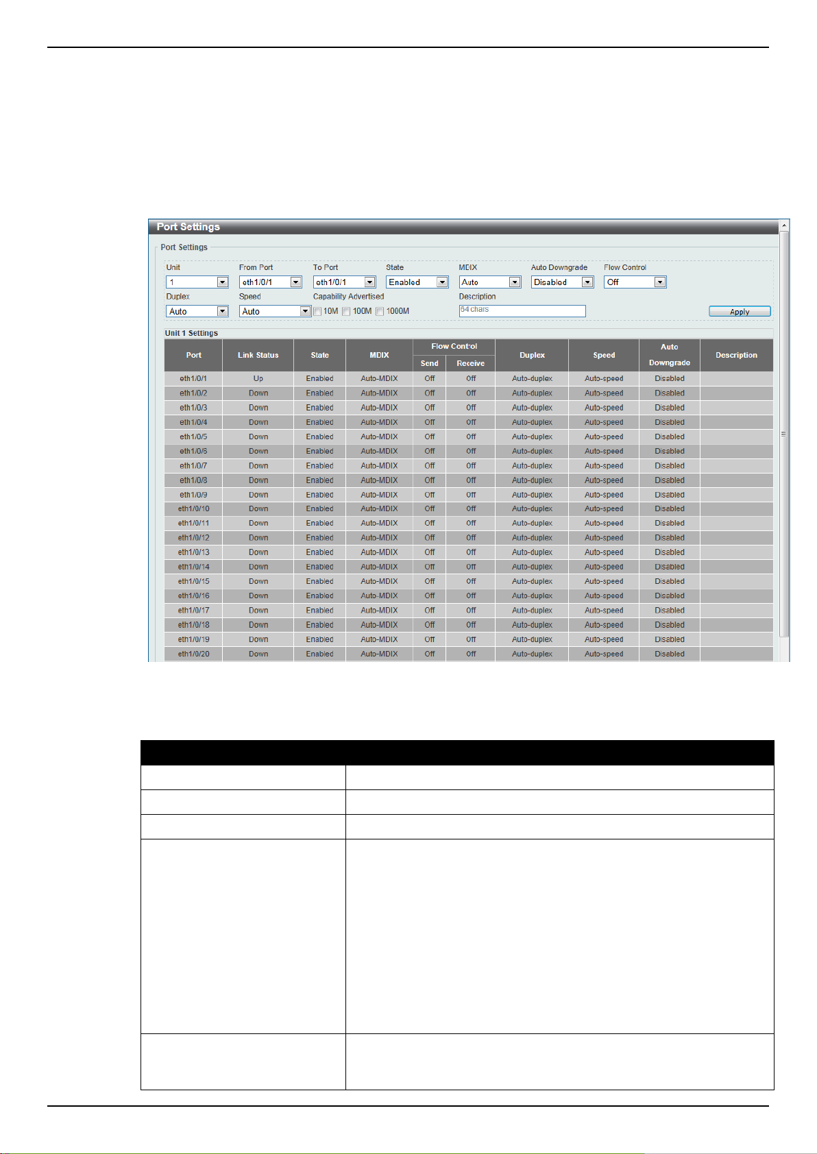
Parameter
Description
Unit
Select the switch unit that will be used for this configuration here.
From Port / To Port
Select the appropriate port range used for the configuration here.
State
Select this option to enable or disable the physical port here.
MDIX
Select the Medium Dependent Interface Crossover (MDIX) option
here. Options to choose from are Auto, Normal, and Cross.
Auto - Select this option for auto-sensing of the optimal type of
cabling.
Normal - Select this option for normal cabling. If this option is
selected, the port is in the MDIX mode and can be connected to a
PC’s NIC using a straight-through cable or a port (in the MDIX
mode) on another switch through a cross-over cable.
Cross - Select this option for cross cabling. If this option is selected,
the port is in the MDI mode and can be connected to a port (in the
MDIX mode) on another switch through a straight cable.
Auto Downgrade
Select this option to enable or disable automatically downgrading
advertised speed in case a link cannot be established at the
available speed.
Port Configuration
Port Settings
This window is used to view and configure the Switch’s port settings.
To view the following window, click System > Port Configuration > Port Settings, as shown below:
Figure 3-4 Port Settings window
The fields that can be configured are described below:
11
Page 20

DGS-1510 Series Gigabit Ethernet SmartPro Switch Web UI Reference Guide
Flow Control
Select to either turn flow control On or Off here. Ports configured for
full-duplex use 802.3x flow control, half-duplex ports use backpressure flow control, and Auto ports use an automatic selection of
the two.
Duplex
Select the duplex mode used here. Options to choose from are
Auto, Half, and Full.
Speed
Select the port speed option here. This option will manually force
the connected on the selected port to only connect at the speed
specified here. Options to choose from are Auto, 10M, 100M,
1000M, 1000M Master, 1000M Slave, and 10G. The Switch allows
users to configure two types of gigabit connections; 1000M Master
and 1000M Slave which refer to connections running a 1000BASE-
T cable for connection between the Switch port and another device
capable of a gigabit connection. The master setting (1000M Master)
will allow the port to advertise capabilities related to duplex, speed
and physical layer type. The master setting will also determine the
master and slave relationship between the two connected physical
layers. This relationship is necessary for establishing the timing
control between the two physical layers. The timing control is set on
a master physical layer by a local source. The slave setting (1000M
Slave) uses loop timing, where the timing comes from a data stream
received from the master. If one connection is set for 1000M
Master, the other side of the connection must be set for 1000M
Slave. Any other configuration will result in a link down status for
both ports.
Capability Advertised
When the Speed is set to Auto, these capabilities are advertised
during auto-negotiation.
Description
Enter a 64 characters description for the corresponding port here.
Click the Apply button to accept the changes made.
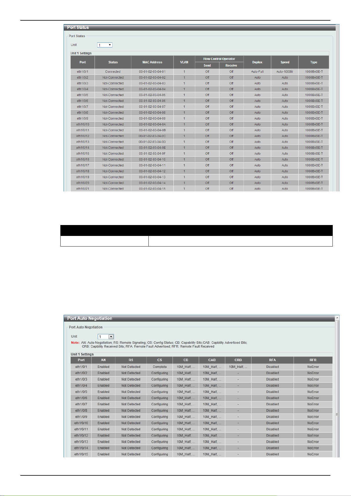
Port Status
This window is used to view the Switch’s physical port status and settings.
To view the following window, click System > Port Configuration > Port Status, as shown below:
12
Page 21
DGS-1510 Series Gigabit Ethernet SmartPro Switch Web UI Reference Guide
Parameter
Description
Unit
Select the switch unit that will be used for this configuration here.
The fields that can be configured are described below:
Port Auto Negotiation
This window is used to view detailed port auto-negotiation information.
To view the following window, click System > Port Configuration > Port Auto Negotiation, as
shown below:
Figure 3-5 Port Status window
Figure 3-6 Port Auto Negotiation window
13
Page 22
DGS-1510 Series Gigabit Ethernet SmartPro Switch Web UI Reference Guide
Parameter
Description
Unit
Select the switch unit that will be used for this configuration here.
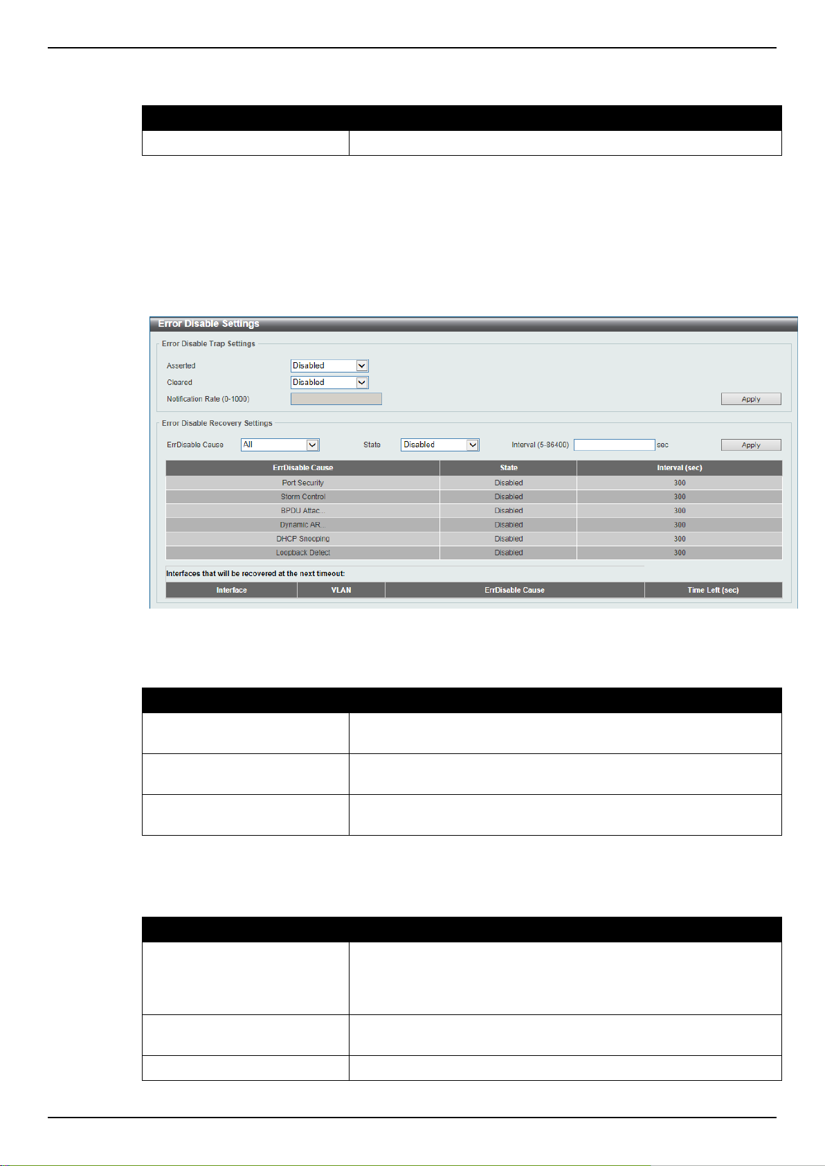
Parameter
Description
Asserted
Select this option to enable or disable the notifications when
entering into the error disabled state.
Cleared
Select this option to enable or disable the notifications when exiting
from the error disabled state.
Notification Rate
Enter the number of traps per minute. The packets that exceed the
rate will be dropped. The value is between 0 and 1000.
Parameter
Description
ErrDisable Cause
Select the error disable causes here. Options to choose from are
All, Port Security, Storm Control, BPDU Attack Protection,
Dynamic ARP Inspection, DHCP Snooping, and Loopback
Detect.
State
Select this option to enable or disable the auto-recovery for an error
port caused by the specified cause.
Interval
Enter the time between 5 and 86400 seconds to recover the port.
The fields that can be configured are described below:
Error Disable Settings
This window is used to configure the sending of SNMP notifications for error disable state.
To view the following window, click System > Port Configuration > Error Disable Settings, as
shown below:
Figure 3-7 Error Disable Settings window
The fields that can be configured for Error Disable Trap Settings are described below:
Click the Apply button to accept the changes made.
The fields that can be configured for Error Disable Recovery Settings are described below:
Click the Apply button to accept the changes made.
14
Page 23
DGS-1510 Series Gigabit Ethernet SmartPro Switch Web UI Reference Guide
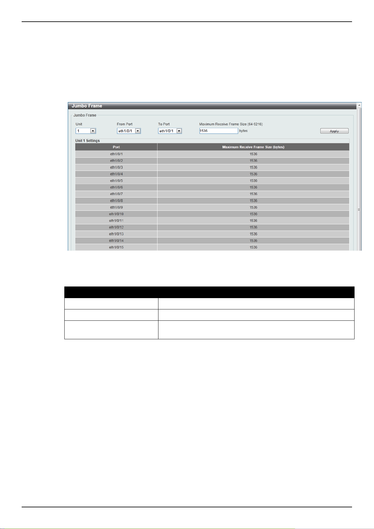
Parameter
Description
Unit
Select the switch unit that will be used for this configuration here.
From Port / To Port
Select the appropriate port range used for the configuration here.
Maximum Receive Frame
Size
Enter the maximum receive frame size value here. This value must
be between 64 and 9216 bytes. By default, this value is 1536 bytes.
Jumbo Frame
This window is used to view and configure the Jumbo Frame size and settings. The Switch supports
jumbo frames. Jumbo frames are Ethernet frames with more than 1,518 bytes of payload. The Switch
supports jumbo frames with a maximum frame size of up to 9216 bytes.
To view the following window, click System > Port Configuration > Jumbo Frame, as shown below:
Figure 3-8 Jumbo Frame window
The fields that can be configured are described below:
Click the Apply button to accept the changes made.
PoE (DGS-1510-28P and DGS-1510-28XMP Only)
The DGS-1510-28P and DGS-1510-28XMP switches support Power over Ethernet (PoE) as defined
by the IEEE 802.3af and 802.3at. All ports can support PoE up to 30W. Ports 1-24 can supply about
48 VDC power to Powered Devices (PDs) over Category 5 or Category 3 UTP Ethernet cables. The
Switch follows the standard PSE (Power Sourcing Equipment) pin-out Alternative A, whereby power is
sent out over pins 1, 2, 3 and 6. The Switches work with all D-Link 802.3af capable devices.
The Switch includes the following PoE features:
Auto-discovery recognizes the connection of a PD (Powered Device) and automatically sends
power to it.
The Auto-disable feature occurs under two conditions: firstly, if the total power consumption
exceeds the system power limit; and secondly, if the per port power consumption exceeds the
per port power limit.
Active circuit protection automatically disables the port if there is a short. Other ports will remain
active.
15
Page 24
DGS-1510 Series Gigabit Ethernet SmartPro Switch Web UI Reference Guide
Based on 802.3af/at PDs receive power according to
the following classification:
PSE provides power according to the following classification:
Class
Maximum power used by PD
Class
Max power supplied by PSE
0
12.95W
0
16.2W
1
3.84W
1
4.2W
2
6.49W
2
7.4W
3
12.95W
3
16.2W
4
25.5W
4
31.6W
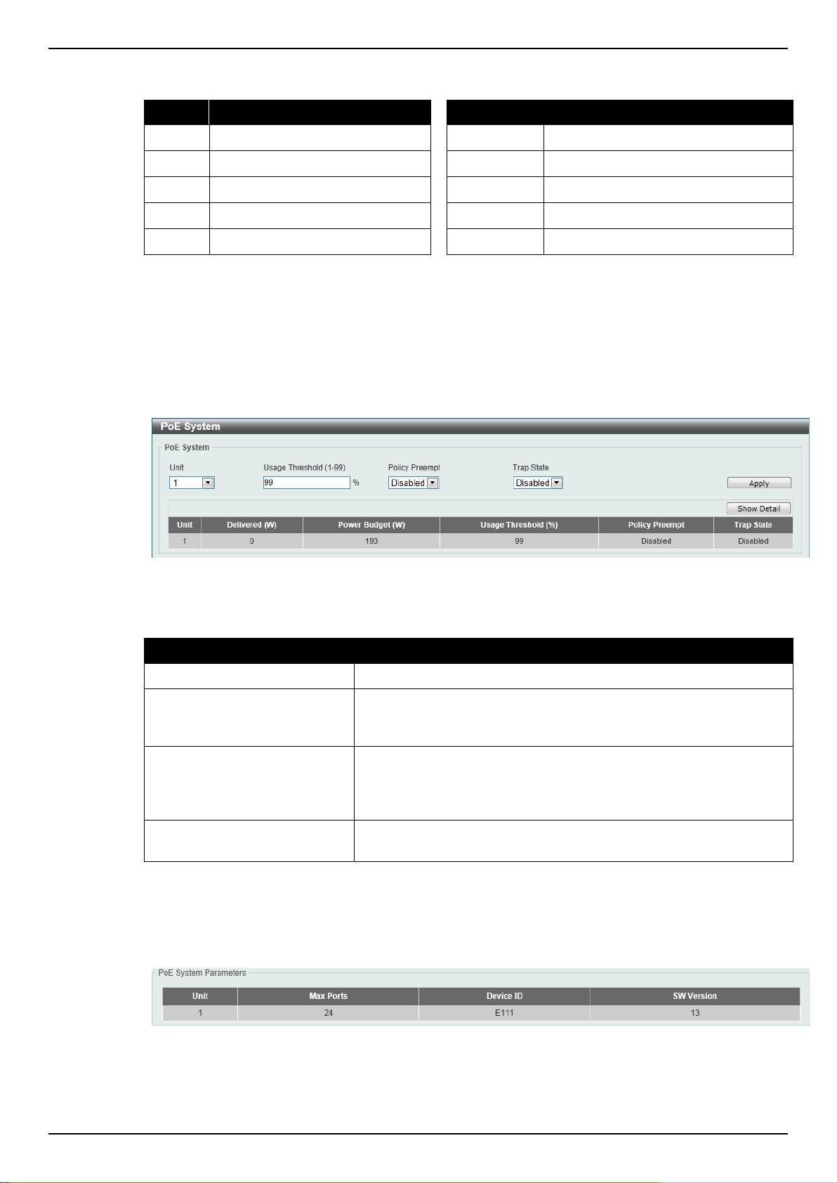
Parameter
Description
Unit
Select the switch unit that will be used for this configuration here.
Usage Threshold
Enter the usage threshold to generate a log and send the
corresponding standard notification. The range is from 1 to 99
percent.
Policy Preempt
Select this option to enable or disable the disconnection of PD
which in power-provisioned with lower priority in order to release the
power to the new connected PD with higher priority under power
shortage conditions.
Trap State
Select this option to enable or disable the sending of PoE
notifications.
PoE System
This window is used to configure the PoE system, and display the detailed power information and PoE
chip parameters for PoE modules.
To view the following window, click System > PoE > PoE System, as shown below:
Figure 3-9 PoE System window
The fields that can be configured are described below:
Click the Apply button to accept the changes made.
Click the Show Detail button to see the PoE system Parameters table at the bottom of the window.
After clicking the Show Detail button, the following table will appear.
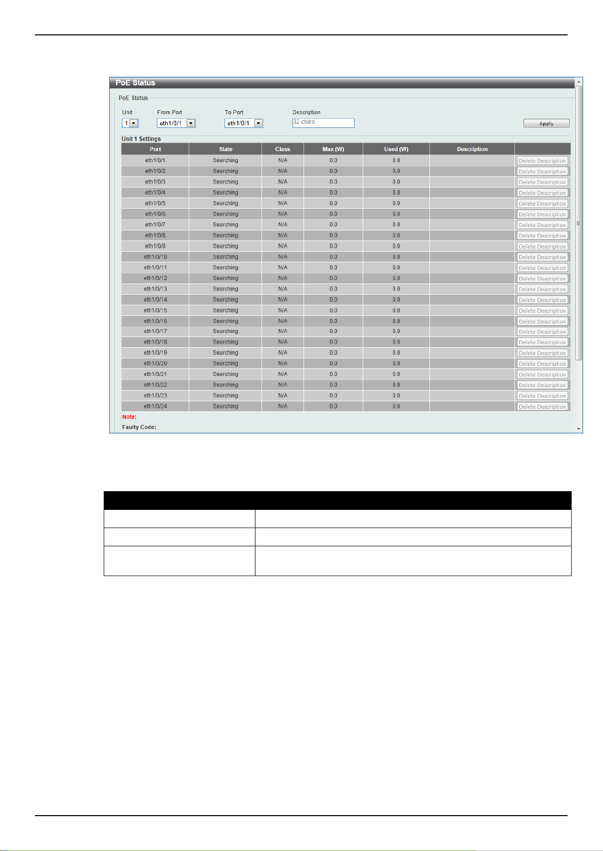
PoE Status
This window is used to configure the description, and display the PoE status of each port.
16
Page 25
DGS-1510 Series Gigabit Ethernet SmartPro Switch Web UI Reference Guide
Parameter
Description
Unit
Select the switch unit that will be used for this configuration here.
From Port / To Port
Select the appropriate port range used for the configuration here.
Description
Enter the text that describes the PD connected to a PoE interface.
The maximum length is 32 characters.
To view the following window, click System > PoE > PoE Status, as shown below:
The fields that can be configured are described below:
Click the Delete Description button to clear the setting in the corresponding Description field.
Click the Apply button to accept the changes made.
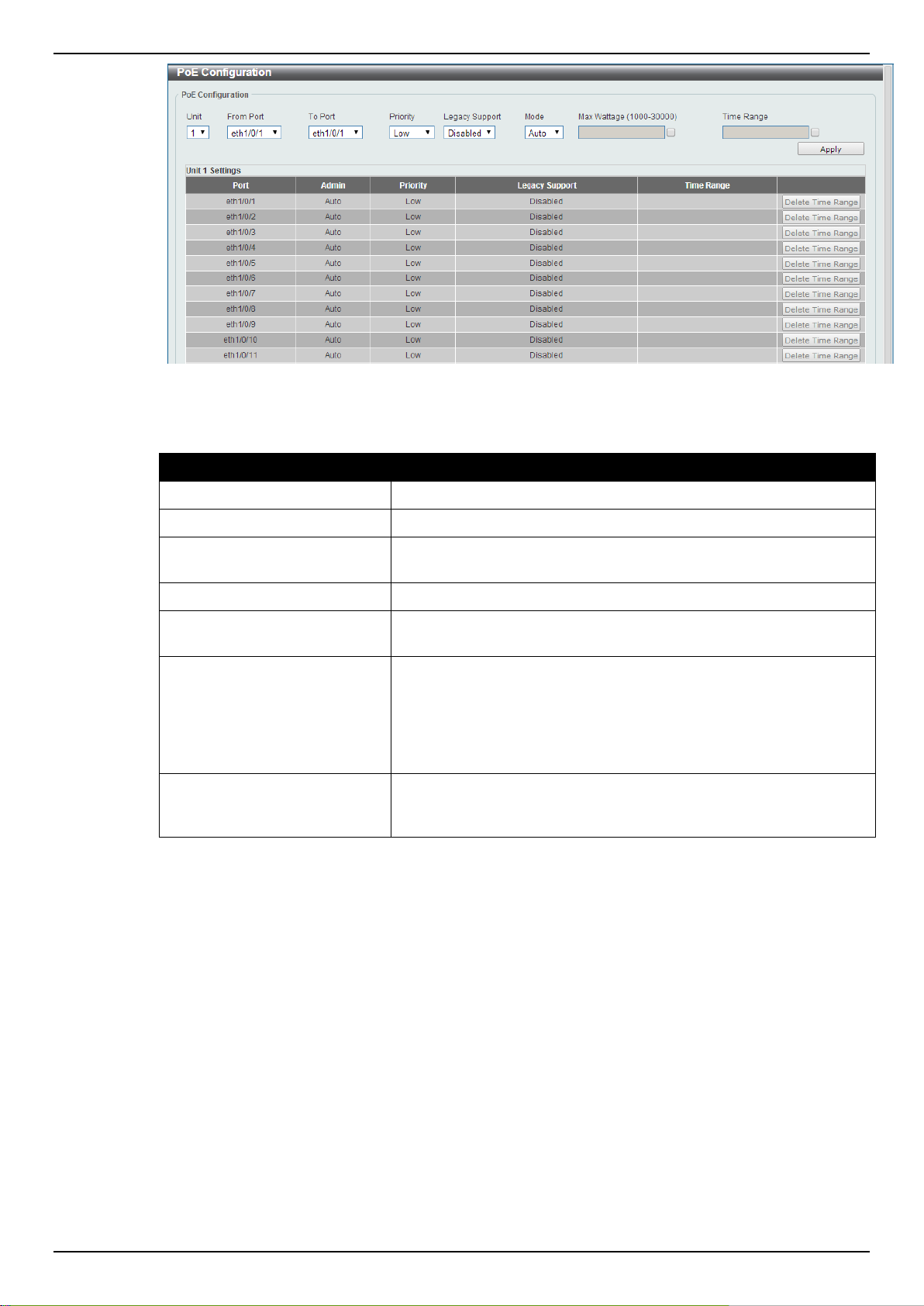
PoE Configuration
This window is used to configure the PoE port.
To view the following window, click System > PoE > PoE Configuration, as shown below:
Figure 3-10 PoE Status window
17
Page 26
DGS-1510 Series Gigabit Ethernet SmartPro Switch Web UI Reference Guide
Parameter
Description
Unit
Select the switch unit that will be used for this configuration here.
From Port / To Port
Select the appropriate port range used for the configuration here.
Priority
Select the priority for provisioning power to the port. Options to
choose from are Critical, High and Low.
Legacy Support
Select this option to enable or disable the support of legacy PD.
Mode
Select the power management mode for the PoE ports. Options to
choose from are Auto and Never.
Max Wattage
When selecting Auto in the Mode drop-down list, this option
appears. Tick the check box and enter the maximum wattage of
power that can be provisioned to the auto-detected PD. If the value
is not entered, the class of the PD automatically determines the
maximum wattage which can be provisioned. The valid range for
maximum wattage is between 1000 mW and 30000 mW.
Time Range
When selecting Auto in the Mode drop-down list, this option
appears. Tick the check box and enter the name of the time range
to determine the activation period.
Figure 3-11 PoE Configuration window
The fields that can be configured are described below:
Click the Delete Time Range button to clear the setting in the corresponding Time Range field.
Click the Apply button to accept the changes made.
PoE Statistics
This window is used to display the PoE statistics.
To view the following window, click System > PoE > PoE Statistics, as shown below:
18
Page 27
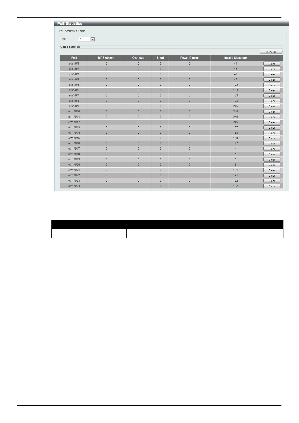
DGS-1510 Series Gigabit Ethernet SmartPro Switch Web UI Reference Guide
Parameter
Description
Unit
Select the switch unit that will be used for this configuration here.
The fields that can be configured are described below:
Click the Clear All button to clear PoE statistics for all ports.
Click the Clear button to clear the PoE statistics for the corresponding port.
PoE Measurement
This window is used to display the PoE measurement.
To view the following window, click System > PoE > PoE Measurement, as shown below:
Figure 3-12 PoE Statistics window
19
Page 28
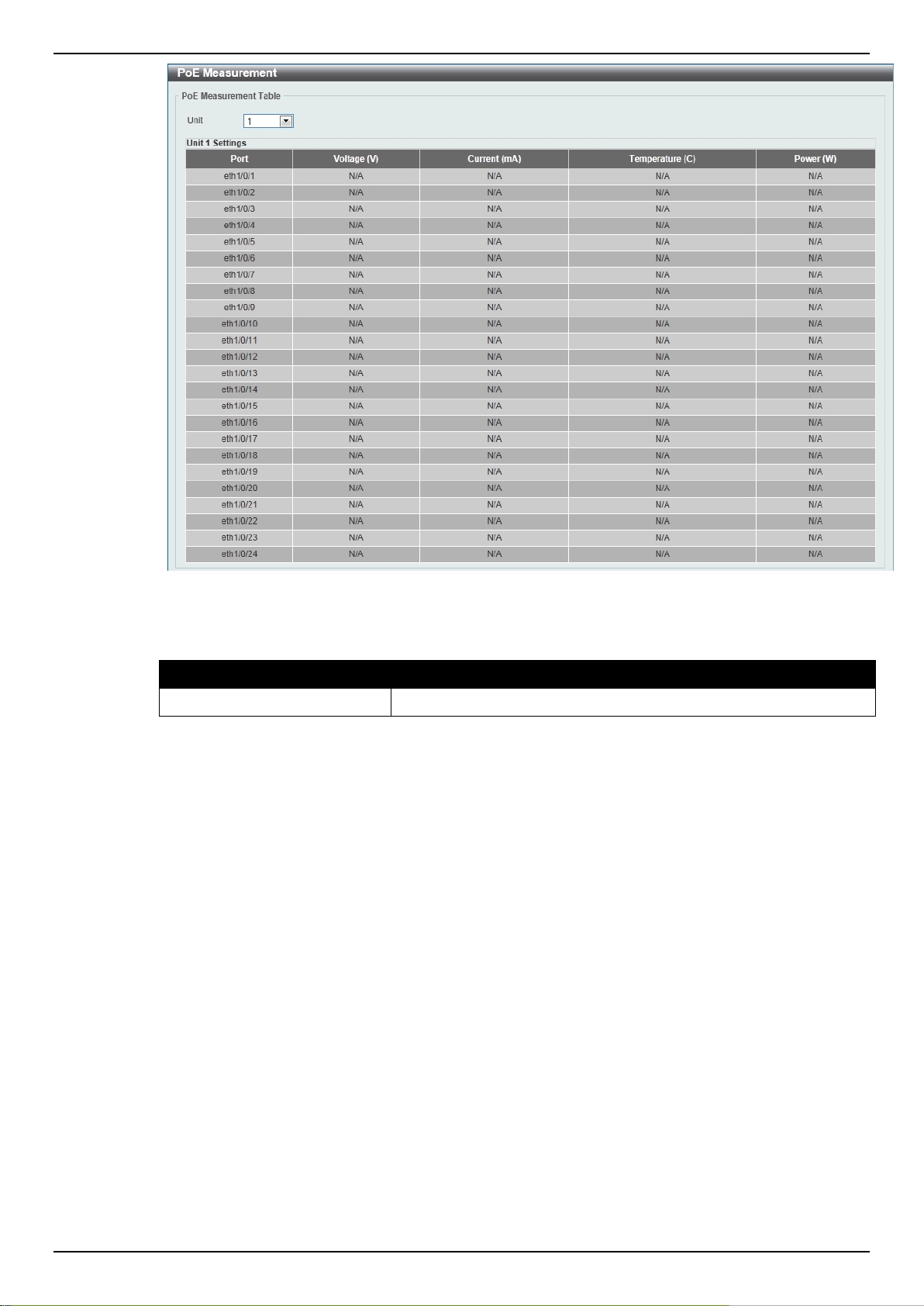
DGS-1510 Series Gigabit Ethernet SmartPro Switch Web UI Reference Guide
Parameter
Description
Unit
Select the switch unit that will be used for this configuration here.
Figure 3-13 PoE Measurement window
The fields that can be configured are described below:
PoE LLDP Classification
This window is used to display the PoE LLDP Classification.
To view the following window, click System > PoE > PoE LLDP Classification, as shown below:
20
Page 29
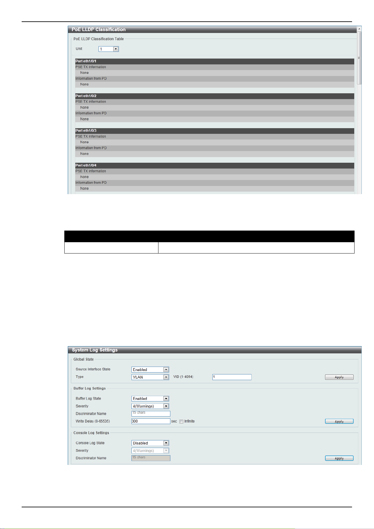
DGS-1510 Series Gigabit Ethernet SmartPro Switch Web UI Reference Guide
Parameter
Description
Unit
Select the switch unit that will be used for this configuration here.
Figure 3-14 PoE LLDP Classification window
The fields that can be configured are described below:
System Log
System Log Settings
This window is used to view and configure the system’s log settings.
To view the following window, click System > System Log > System Log Settings, as shown below:
Figure 3-15 System Log Settings window
The fields that can be configured for Global State are described below:
21
Page 30

DGS-1510 Series Gigabit Ethernet SmartPro Switch Web UI Reference Guide
Parameter
Description
Source Interface State
Select this option to enable or disable the source interface’s global
state.
Type
Select the type of interface that will be used. Option to choose from
is VLAN.
VID
Enter the VLAN ID used here. The value is between 1 and 4094.
Parameter
Description
Buffer Log State
Select whether the enable or disable the buffer log’s global state
here. Options to choose from are Enable, Disabled, and Default.
When selecting the Default option, the buffer log’s global state will
follow the default behavior.
Severity
Select the severity value of the type of information that will be
logged. Options to choose from are 0 (Emergencies), 1 (Alerts), 2
(Critical), 3 (Errors), 4 (Warnings), 5 (Notifications), 6
(Informational), and 7 (Debugging).
Discriminator Name
Enter the discriminator name used here. This name can be up to 15
characters long.
Write Delay
Enter the interval for periodic writing of the logging buffer to FLASH.
This value must be between 0 and 65535 seconds. By default, this
value is 300 seconds. Tick the Infinite option, to disable the write
delay feature.
Parameter
Description
Console Log State
Select whether the enable or disable the console log’s global state
here.
Severity
Select the severity value of the type of information that will be
logged. Options to choose from are 0 (Emergencies), 1 (Alerts), 2
(Critical), 3 (Errors), 4 (Warnings), 5 (Notifications), 6
(Informational), and 7 (Debugging).
Discriminator Name
Enter the discriminator name used here. This name can be up to 15
characters long.
Click the Apply button to accept the changes made.
The fields that can be configured for Buffer Log Settings are described below:
Click the Apply button to accept the changes made.
The fields that can be configured for Console Log Settings are described below:
Click the Apply button to accept the changes made.
System Log Discriminator Settings
This window is used to view and configure the system log’s discriminator settings.
To view the following window, click System > System Log > System Log Discriminator Settings,
as shown below:
22
Page 31

DGS-1510 Series Gigabit Ethernet SmartPro Switch Web UI Reference Guide
Parameter
Description
Discriminator Name
Enter the discriminator name here. This name can be up to 15
characters long.
Action
Select the facility’s behavior option and the type of facility that will
be associated with the selected behavior here. Behavior options to
choose from are Drops and Includes.
Severity
Select the severity behavior option and the value of the type of
information that will be logged. Behavior options to choose from are
Drops and Includes. Severity value options to choose from are 0
(Emergencies), 1 (Alerts), 2 (Critical), 3 (Errors), 4 (Warnings), 5
(Notifications), 6 (Informational), and 7 (Debugging).
Figure 3-16 System Log Discriminator Settings window
The fields that can be configured are described below:
Click the Apply button to accept the changes made.
Click the Delete button to remove the specified entry.
System Log Server Settings
This window is used to view and configure system log’s server settings.
To view the following window, click System > System Log > System Log Server Settings, as
shown below:
Figure 3-17 System Log Server Settings window
The fields that can be configured are described below:
23
Page 32

DGS-1510 Series Gigabit Ethernet SmartPro Switch Web UI Reference Guide
Parameter
Description
Host IPv4 Address
Enter the system log server’s IPv4 address here.
Host IPv6 Address
Enter the system log server’s IPv6 address here.
UDP Port
Enter the system log server’s UDP port number here. This value
must be 514 or between 1024 and 65535. By default, this value is
514.
Severity
Select the severity value of the type of information that will be
logged. Options to choose from are 0 (Emergencies), 1 (Alerts), 2
(Critical), 3 (Errors), 4 (Warnings), 5 (Notifications), 6
(Informational), and 7 (Debugging).
Facility
Select the facility value here. Options to choose from are 0 to 23.
Discriminator Name
Enter the discriminator name here. This name can be up to 15
characters long.
Click the Apply button to accept the changes made.
Click the Delete button to remove the specified entry.
System Log
This window is used to view and clear the system log.
To view the following window, click System > System Log > System Log, as shown below:
Click the Clear Log button to clear the system log entries displayed in the table.
Enter a page number and click the Go button to navigate to a specific page when multiple pages exist.
System Attack Log
This window is used to view and clear the system attack log.
Figure 3-18 System Log window
To view the following window, click System > System Log > System Attack Log, as shown below:
Figure 3-19 System Attack Log window
The fields that can be configured are described below:
24
Page 33

DGS-1510 Series Gigabit Ethernet SmartPro Switch Web UI Reference Guide
Parameter
Description
Unit
Select the switch unit that will be used for this configuration here.
Parameter
Description
Time (HH:MM:SS)
Enter the current time in hours, minutes, and seconds.
Date (DD / MM / YYYY)
Enter the current day, month, and year to update the system clock.
Click the Clear Attack Log button to clear the system attack log entries displayed in the table.
Time and SNTP
The Simple Network Time Protocol (SNTP) is a protocol for synchronizing computer clocks through
the Internet. It provides comprehensive mechanisms to access national time and frequency
dissemination services, organize the SNTP subnet of servers and clients, and adjust the system clock
in each participant.
Clock Settings
This window is used to configure the time settings for the Switch.
To view the following window, click System > Time and SNTP > Clock Settings, as shown below:
The fields that can be configured are described below:
Click the Apply button to accept the changes made.
Time Zone Settings
This window is used to configure time zones and Daylight Savings Time settings for SNTP.
To view the following window, click System > Time and SNTP > Time Zone Settings, as shown
below:
Figure 3-20 Clock Settings window
25
Page 34

DGS-1510 Series Gigabit Ethernet SmartPro Switch Web UI Reference Guide
Parameter
Description
Summer Time State
Select the summer time setting. Options to choose from are
Disabled, Recurring Setting, and Date Setting.
Disabled - Select to disable the summer time setting.
Recurring Setting - Select to configure the summer time that
should start and end on the specified week day of the specified
month.
Date Setting - Select to configure the summer time that should start
and end on the specified date of the specified month.
Time Zone
Select to specify your local time zone’s offset from Coordinated
Universal Time (UTC).
Parameter
Description
From: Week of the Month
Select week of the month that summer time will start.
From: Day of the Week
Select the day of the week that summer time will start.
From: Month
Select the month that summer time will start.
From: Time (HH:MM)
Select the time of the day that summer time will start.
To: Week of the Month
Select week of the month that summer time will end.
To: Day of the Week
Select the day of the week that summer time will end.
To: Month
Select the month that summer time will end.
To: Time (HH:MM)
Select the time of the day that summer time will end.
Figure 3-21 Time Zone Settings window
The fields that can be configured are described below:
The fields that can be configured for Recurring Setting are described below:
26
Page 35

DGS-1510 Series Gigabit Ethernet SmartPro Switch Web UI Reference Guide
Offset
Enter the number of minutes to add during summer time. The
default value is 60. The range of this offset is 30, 60, 90 and 120.
Parameter
Description
From: Date of the Month
Select date of the month that summer time will start.
From: Month
Select the month that summer time will start.
From: Year
Enter the year that the summer time will start.
From: Time (HH:MM)
Select the time of the day that summer time will start.
To: Date of the Month
Select date of the month that summer time will end.
To: Month
Select the month that summer time will end.
To: Year
Enter the year that the summer time will end.
To: Time (HH:MM)
Select the time of the day that summer time will end.
Offset
Enter the number of minutes to add during summer time. The
default value is 60. The range of this offset is 30, 60, 90 and 120.
Parameter
Description
SNTP State
Select this option to enable or disable SNTP.
Poll Interval
Enter the synchronizing interval in seconds. The value is from 30 to
99999 seconds. The default interval is 720 seconds.
Parameter
Description
The fields that can be configured for Date Setting are described below:
Click the Apply button to accept the changes made.
SNTP Settings
This window is used to configure the time settings for the Switch.
To view the following window, click System > Time and SNTP > SNTP Settings, as shown below:
Figure 3-22 SNTP Settings window
The fields that can be configured for SNTP Global Settings are described below:
Click the Apply button to accept the changes made.
The fields that can be configured for SNTP Server Setting are described below:
27
Page 36

DGS-1510 Series Gigabit Ethernet SmartPro Switch Web UI Reference Guide
IPv4 Address
Enter the IP address of the SNTP server which provides the clock
synchronization.
IPv6 Address
Enter the IPv6 address of the SNTP server which provides the clock
synchronization.
Parameter
Description
Range Name
Enter the name of the time range. This name can be up to 32
characters long.
From Week / To Week
Select the starting and ending days of the week that will be used for
this time range. Tick the Daily option to use this time range for
every day of the week. Tick the End Week Day option to use this
time range from the starting day of the week until the end of the
week, which is Sunday.
From Time / To Time
Select the starting and ending time of the day that will be used for
this time range. The first drop-down menu selects the hour and the
second drop-down menu selects the minute.
Click the Add button to add the SNTP server.
Click the Delete button to remove the specified entry.
Time Range
This window is used to view and configure the time range settings.
To view the following window, click System > Time Range, as shown below:
Figure 3-23 Time Range window
The fields that can be configured are described below:
Click the Apply button to accept the changes made.
Click the Find button to locate a specific entry based on the information entered.
Click the Delete Periodic button to delete the periodic entry.
Click the Delete button to remove the specified entry.
Enter a page number and click the Go button to navigate to a specific page when multiple pages exist.
28
Page 37

DGS-1510 Series Gigabit Ethernet SmartPro Switch Web UI Reference Guide
Parameter
Description
User Name
Enter the user account name here. This name can be up to 32
4. Management
User Account Settings
Password Encryption
Login Method
SNMP
RMON
Telnet/Web
Session Timeout
DHCP
DNS
NTP
IP Source Interface
File System
Physical Stacking
Virtual Stacking (SIM)
D-Link Discovery Protocol
User Account Settings
This window is used to create and configure the user accounts. The active user account sessions can
be viewed.
There are several configuration options available in the Web User Interface (Web UI). The set of
configuration options available to the user depends on the account’s Privilege Level. A user account
created with a higher privilege level will be given access to configure more features than a user
account created with a lower privilege level.
The pre-defined user account privilege levels supported by this switch are:
Basic User - Privilege Level 1. This user account level has the lowest priority of the user
accounts. The purpose of this type of user account level is for basic system checking.
Operator - Privilege Level 12. This user account level is used to grant system configuration
rights for users who need to change or monitor system configuration, except for security
related information such as user accounts and SNMP account settings.
Administrator - Privilege Level 15. This administrator user account level can monitor all
system information and change any of the system configuration settings expressed in this
guide.
To view the following window, click Management > User Account Settings, as shown below:
Figure 4-1 User Management Settings window
The fields that can be configured are described below:
29
Page 38

DGS-1510 Series Gigabit Ethernet SmartPro Switch Web UI Reference Guide
characters long.
Privilege
Enter the privilege level for this account here. This value must be
between 1 and 15.
Password Type
Select the password type for this user account here. Options to
choose from are None, Plain Text, Encrypted-SHA1 and
Encrypted-MD5. When selecting Encrypted-SHA1 or EncryptedMD5, the password will not be encrypted from the plain-text format
to the encrypted format. Instead, the encrypted password must be
entered. To encrypt the password from the plain-text format to the
encrypted format, refer to the Password Encryption window.
Password
After selecting Plain Text, Encrypted-SHA1 or Encrypted-MD5 as
the Password Type, enter the password for this user account here.
Parameter
Description
Password Encryption State
Select this option to enable or disable the encryption of the
password before stored in the configuration file.
Password Type
After the Password Encryption State is Enabled, this filed will be
available. Options to choose from are Encrypted-SHA1 and
Click the Apply button to accept the changes made.
Click the Delete button to remove the specified user account entry.
Enter a page number and click the Go button to navigate to a specific page when multiple pages exist.
After clicking the Session Table tab, the following page will appear.
A list of active user account session will be displayed.
Enter a page number and click the Go button to navigate to a specific page when multiple pages exist.
Password Encryption
This window is used to configure whether to save the encryption of the password in the configuration
file.
To view the following window, click Management > Password Encryption, as shown below:
Figure 4-3 Password Encryption window
Figure 4-2 Session Table window
The fields that can be configured are described below:
30
Page 39

DGS-1510 Series Gigabit Ethernet SmartPro Switch Web UI Reference Guide
Encrypted-MD5.
Parameter
Description
Level
Select the password level here. This value must be between 1 and
15.
Password Type
Select the password type here. Options to choose from are Plain
Text, Encrypted-SHA1 and Encrypted-MD5. When selecting
Encrypted-SHA1 or Encrypted-MD5, the password will not be
encrypted from the plain-text format to the encrypted format.
Instead, the encrypted password must be entered. To encrypt the
password from the plain-text format to the encrypted format, refer to
the Password Encryption window.
Password
After selecting Plain Text, Encrypted-SHA1 or Encrypted-MD5 as
the Password Type, enter the password for this user account here.
Parameter
Description
Login Method
After clicking the Edit button this parameter can be configured.
Select the login method for the specified application here. Options
to choose from are No Login, Login and Login Local. No Login,
as the name implies, requires no login authentication to access the
specified application. Login will require the user to at least enter a
password when trying to access the application specified. Login
Local requires the user to enter a username and a password to
Click the Apply button to accept the changes made.
Login Method
This window is used to configure the login method for each management interface that this Switch
supports.
To view the following window, click Management > Login Method, as shown below:
Figure 4-4 Login Method window
The fields that can be configured for Enable Password settings are described below:
Click the Apply button to accept the changes made.
The Login Method section will only be available when Authentication, Authorization, and Accounting
(AAA) feature is disabled. The fields that can be configured for Login Method settings are described
below:
31
Page 40

DGS-1510 Series Gigabit Ethernet SmartPro Switch Web UI Reference Guide
access the specified application.
Parameter
Description
Application
Select the application that will be configured here. Options to
choose from are Console, Telnet and SSH.
Password Type
Select the password encryption type that will be used here. Options
to choose from are Plain Text, Encrypted-SHA1 and Encrypted-
MD5..
Password
Enter the password for the selected application here. This password
will be used when the Login Method for the specified application is
set as Login.
Click the Edit button to modify the corresponding login method.
Click the Apply button to accept the changes made.
The fields that can be configured for Login Password settings are described below:
Click the Apply button to accept the changes made.
Click the Delete button to remove the password from the specified application.
SNMP
Simple Network Management Protocol (SNMP) is an OSI Layer 7 (Application Layer) designed
specifically for managing and monitoring network devices. SNMP enables network management
stations to read and modify the settings of gateways, routers, switches, and other network devices.
Use SNMP to configure system features for proper operation, monitor performance and detect
potential problems in the Switch, switch group or network.
Managed devices that support SNMP include software (referred to as an agent), which runs locally on
the device. A defined set of variables (managed objects) is maintained by the SNMP agent and used
to manage the device. These objects are defined in a Management Information Base (MIB), which
provides a standard presentation of the information controlled by the on-board SNMP agent. SNMP
defines both the format of the MIB specifications and the protocol used to access this information over
the network.
The Switch supports the SNMP versions 1, 2c, and 3. The three versions of SNMP vary in the level of
security provided between the management station and the network device.
In SNMP v.1 and v.2, user authentication is accomplished using ‘community strings’, which function
like passwords. The remote user SNMP application and the Switch SNMP must use the same
community string. SNMP packets from any station that has not been authenticated are ignored
(dropped).
The default community strings for the Switch used for SNMP v.1 and v.2 management access are:
public – Allows authorized management stations to retrieve MIB objects.
private – Allows authorized management stations to retrieve and modify MIB objects.
SNMPv3 uses a more sophisticated authentication process that is separated into two parts. The first
part is to maintain a list of users and their attributes that are allowed to act as SNMP managers. The
second part describes what each user on that list can do as an SNMP manager.
The Switch allows groups of users to be listed and configured with a shared set of privileges. The
SNMP version may also be set for a listed group of SNMP managers. Thus, you may create a group
of SNMP managers that are allowed to view read-only information or receive traps using SNMPv1
32
Page 41

DGS-1510 Series Gigabit Ethernet SmartPro Switch Web UI Reference Guide
while assigning a higher level of security to another group, granting read/write privileges using
SNMPv3.
Using SNMPv3 individual users or groups of SNMP managers can be allowed to perform or be
restricted from performing specific SNMP management functions. The functions allowed or restricted
are defined using the Object Identifier (OID) associated with a specific MIB. An additional layer of
security is available for SNMPv3 in that SNMP messages may be encrypted. To read more about how
to configure SNMPv3 settings for the Switch read the next section.
Traps
Traps are messages that alert network personnel of events that occur on the Switch. The events can
be as serious as a reboot (someone accidentally turned OFF the Switch), or less serious like a port
status change. The Switch generates traps and sends them to the trap recipient (or network manager).
Typical traps include trap messages for Authentication Failure, Topology Change and
Broadcast\Multicast Storm.
MIBs
The Switch in the Management Information Base (MIB) stores management and counter information.
The Switch uses the standard MIB-II Management Information Base module. Consequently, values
for MIB objects can be retrieved from any SNMP-based network management software. In addition to
the standard MIB-II, the Switch also supports its own proprietary enterprise MIB as an extended
Management Information Base. Specifying the MIB Object Identifier may also retrieve the proprietary
MIB. MIB values can be either read-only or read-write.
The Switch incorporates a flexible SNMP management for the switching environment. SNMP
management can be customized to suit the needs of the networks and the preferences of the network
administrator. Use the SNMP V3 menus to select the SNMP version used for specific tasks.
The Switch supports the Simple Network Management Protocol (SNMP) versions 1, 2c, and 3. The
administrator can specify the SNMP version used to monitor and control the Switch. The three
versions of SNMP vary in the level of security provided between the management station and the
network device.
SNMP settings are configured using the menus located on the SNMP V3 folder of the Web manager.
Workstations on the network that are allowed SNMP privileged access to the Switch can be restricted
with the Management Station IP Address menu.
SNMP Global Settings
This window is used to configure the SNMP global settings and trap settings.
To view the following window, click Management > SNMP > SNMP Global Settings, as shown below:
33
Page 42

DGS-1510 Series Gigabit Ethernet SmartPro Switch Web UI Reference Guide
Parameter
Description
SNMP Global State
Select this option to enable or disable the SNMP feature.
SNMP Response Broadcast
Request
Select this option to enable or disable the server to response to
broadcast SNMP GetRequest packets.
SNMP UDP Port
Enter the SNMP UDP port number.
Trap Source Interface
Enter the interface whose IP address will be used as the source
address for sending the SNMP trap packet.
Parameter
Description
Trap Global State
Select this option to enable or disable the sending of all or specific
SNMP notifications.
SNMP Authentication Trap
Tick this option to control the sending of SNMP authentication
failure notifications. An authenticationFailuretrap is generated when
the device receives an SNMP message that is not properly
authenticated. The authentication method depends on the version of
SNMP being used. For SNMPv1 or SNMPv2c, authentication failure
occurs if packets are formed with an incorrect community string. For
SNMPv3, authentication failure occurs if packets are formed with an
incorrect SHA/MD5 authentication key.
Port Link Up
Tick this option to control the sending of port link up notifications. A
linkup trap is generated when the device recognizes that one of the
communication links has come up.
Port Link Down
Tick this option to control the sending of port link down notifications.
A linkDown trap is generated when the device recognizes a failure
in one of the communication links.
Coldstart
Tick this option to control the sending of SNMP coldStart
notifications.
Warmstart
Tick this option to control the sending of SNMP warmStart
notifications.
Figure 4-5 SNMP Global Settings window
The fields that can be configured for SNMP Global Settings are described below:
The fields that can be configured for Trap Settings are described below:
Click the Apply button to accept the changes made.
SNMP Linkchange Trap Settings
This window is used to configure the SNMP link change trap settings.
34
Page 43

DGS-1510 Series Gigabit Ethernet SmartPro Switch Web UI Reference Guide
Parameter
Description
Unit
Select the switch unit that will be used for this configuration here.
From Port / To Port
Select the appropriate port range used for the configuration here.
Trap Sending
Select this option to enable or disable the sending of the SNMP
notification traps that is generated by the system.
Trap State
Select this option to enable or disable the SNMP link change trap.
To view the following window, click Management > SNMP > SNMP Linkchange Trap Settings, as
shown below:
Figure 4-6 SNMP Linkchange Trap Settings window
The fields that can be configured are described below:
Click the Apply button to accept the changes made.
SNMP View Table Settings
This window is used to assign views to community strings that define which MIB objects can be
accessed by a remote SNMP manager. The SNMP Group created with this table maps SNMP users
(identified in the SNMP User Table) to the views created in the previous window.
To view the following window, click Management > SNMP > SNMP View Table Settings, as shown
below:
35
Page 44

DGS-1510 Series Gigabit Ethernet SmartPro Switch Web UI Reference Guide
Parameter
Description
View Name
Type an alphanumeric string of up to 32 characters. This is used to
identify the new SNMP view being created.
Subtree OID
Type the Object Identifier (OID) Subtree for the view. The OID
identifies an object tree (MIB tree) that will be included or excluded
from access by an SNMP manager.
View Type
Select the view type here. Options to choose from are Included,
and Excluded.
Included - Select to include this object in the list of objects that an
SNMP manager can access.
Excluded - Select to exclude this object from the list of objects that
an SNMP manager can access.
Figure 4-7 SNMP View Table Settings window
The fields that can be configured are described below:
Click the Add button to add a new entry based on the information entered.
Click the Delete button to remove the specified entry.
SNMP Community Table Settings
This window is used to create an SNMP community string to define the relationship between the
SNMP manager and an agent. The community string acts like a password to permit access to the
agent on the Switch. One or more of the following characteristics can be associated with the
community string:
An Access List of IP addresses of SNMP managers that are permitted to use the community
string to gain access to the Switch’s SNMP agent.
Any MIB view that defines the subset of all MIB objects will be accessible to the SNMP
community.
Read/write or read-only level permission for the MIB objects accessible to the SNMP community.
To view the following window, click Management > SNMP > SNMP Community Table Settings, as
shown below:
36
Page 45

DGS-1510 Series Gigabit Ethernet SmartPro Switch Web UI Reference Guide
Parameter
Description
Key Type
Select the key type for the SNMP community. Options to choose
from are Plain Text, and Encrypted.
Community Name
Enter an alphanumeric string of up to 32 characters that is used to
identify members of an SNMP community. This string is used like a
password to give remote SNMP managers access to MIB objects in
the Switch’s SNMP agent.
View Name
Enter an alphanumeric string of up to 32 characters that is used to
identify the group of MIB objects that a remote SNMP manager is
allowed to access on the Switch. The view name must exist in the
SNMP View Table.
Access Right
Select the access right here. Options to choose from are Read
Only, and Read Write.
Read Only - SNMP community members using the community
string created can only read the contents of the MIBs on the Switch.
Read Write - SNMP community members using the community
string created can read from, and write to the contents of the MIBs
on the Switch.
IP Access-List Name
Enter the name of the standard access list to control the user to use
this community string to access to the SNMP agent.
Figure 4-8 SNMP Community Table Settings window
The fields that can be configured are described below:
Click the Add button to add a new entry based on the information entered.
Click the Delete button to remove the specified entry.
SNMP Group Table Settings
An SNMP Group created with this table maps SNMP users (identified in the SNMP User Table) to the
views created in the previous window.
To view the following window, click Management > SNMP > SNMP Group Table Settings, as shown
below:
37
Page 46

DGS-1510 Series Gigabit Ethernet SmartPro Switch Web UI Reference Guide
Parameter
Description
Group Name
Enter the group name of a maximum of 32 characters. The syntax is
general string that does not allow space.
User-based Security Model
Select the security model here. Options to choose from are
SNMPv1, SNMPv2c, and SNMPv3.
SNMPv1 - Select to allow the group user to use the SNMPv1
security model.
SNMPv2c - Select to allow the group user to use the SNMPv2c
security model.
SNMPv3 - Select to allow the group user to use the SNMPv3
security model.
Security Level
When selecting SNMPv3 in the User-based Security Model dropdown list, this option is available.
NoAuthNoPriv - Specify that there will be no authorization and no
encryption of packets sent between the Switch and a remote SNMP
manager.
AuthNoPriv - Specify that authorization will be required, but there
will be no encryption of packets sent between the Switch and a
remote SNMP manager.
AuthPriv - Specify that authorization will be required, and that
packets sent between the Switch and a remote SNMP manger will
be encrypted.
IP Address-List Name
Enter the standard IP access control list (ACL) to associate with the
group.
Read View Name
Enter the read view name that the group user can access.
Write View Name
Enter the write view name that the group user can access.
Notify View Name
Enter a write view name that the group user can access. The notify
view describes the object that can be reported its status via trap
packets to the group user.
Figure 4-9 SNMP Group Table Settings window
The fields that can be configured are described below:
Click the Add button to add a new entry based on the information entered.
SNMP Engine ID Local Settings
Click the Delete button to remove the specified entry.
The Engine ID is a unique identifier used for SNMP V3 implementations on the Switch.
38
Page 47

DGS-1510 Series Gigabit Ethernet SmartPro Switch Web UI Reference Guide
Parameter
Description
Engine ID
Enter the engine ID string with the maximum of 24 characters.
Parameter
Description
User Name
Enter an alphanumeric string of up to 32 characters. This is used to
identify the SNMP users.
Group Name
Enter the SNMP group name to which the user belongs. The syntax
is general string that does not allow spaces.
SNMP Version
Select the SNMP version. Options to choose from are v1, v2c, and
v3.
SNMP V3 Encryption
When selecting v3 in the SNMP Version drop-down list, this option
To view the following window, click Management > SNMP > SNMP Engine ID Local Settings, as
shown below:
Figure 4-10 SNMP Engine ID Local Settings window
The fields that can be configured are described below:
Click the Default button to revert the engine ID to the default.
Click the Apply button to accept the changes made.
SNMP User Table Settings
This window is used to configure and display the SNMP users that are currently configured on the
Switch.
To view the following window, click Management > SNMP > SNMP User Table Settings, as shown
below:
Figure 4-11 SNMP User Table Settings window
The fields that can be configured are described below:
39
Page 48

DGS-1510 Series Gigabit Ethernet SmartPro Switch Web UI Reference Guide
is available. Options to choose from are None, Password, and
Key.
Auth-Protocol
When selecting v3 in the SNMP Version drop-down list, and
selecting either Password or Key in the SNMP V3 Encryption dropdown list, this option is available. Select the authentication level.
Options to choose from are MD5, and SHA.
MD5 - Select to use the HMAC-MD5-96 authentication level. This
field will require the user to enter a password or a key.
SHA - Specify that the HMAC-SHA authentication protocol will be
used. This field will require the user to enter a password or a key.
Priv-Protocol
When selecting v3 in the SNMP Version drop-down list, and
selecting either Password or Key in the SNMP V3 Encryption dropdown list, this option is available. Select the private protocol.
Options to choose from are None, and DES56.
None - Specify that no authorization protocol is in use.
DES56 - Specify that DES 56-bit encryption is in use, based on the
CBC-DES (DES-56) standard. This field will require the user to
enter a password or a key.
IP Address-List Name
Enter the standard IP access control list (ACL) to associate with the
user.
Parameter
Description
Host IPv4 Address
Enter the IPv4 address of the SNMP notification host.
Host IPv6 Address
Enter the IPv6 address of the SNMP notification host.
User-based Security Model
Select the security model here. Options to choose from are
SNMPv1, SNMPv2c, and SNMPv3.
SNMPv1 - Select to allow the group user to use the SNMPv1
security model.
SNMPv2c - Select to allow the group user to use the SNMPv2c
Click the Add button to add a new entry based on the information entered.
Click the Delete button to remove the specified entry.
SNMP Host Table Settings
This window is used to configure and display the recipient of the SNMP notification.
To view the following window, click Management > SNMP > SNMP Host Table Settings, as shown
below:
Figure 4-12 SNMP Host Table Settings
The fields that can be configured are described below:
40
Page 49

DGS-1510 Series Gigabit Ethernet SmartPro Switch Web UI Reference Guide
security model.
SNMPv3 - Select to allow the group user to use the SNMPv3
security model.
Security Level
When selecting SNMPv3 in the User-based Security Model dropdown list, this option is available.
NoAuthNoPriv - Specify that there will be no authorization and no
encryption of packets sent between the Switch and a remote SNMP
manager.
AuthNoPriv - Specify that authorization will be required, but there
will be no encryption of packets sent between the Switch and a
remote SNMP manager.
AuthPriv - Specify that authorization will be required, and that
packets sent between the Switch and a remote SNMP manger will
be encrypted.
UDP Port
Enter the UDP port number. The default trap UDP port number is
162. The range of UDP port numbers is from 0 to 65535. Some port
numbers may conflict with other protocols.
Community String / SNMPv3
User Name
Enter the community string to be sent with the notification packet.
Parameter
Description
RMON Rising Alarm Trap
Select this option to enable or disable the RMON Rising Alarm Trap
Feature.
RMON Falling Alarm Trap
Select this option to enable or disable the RMON Falling Alarm Trap
Feature.
Click the Add button to add a new entry based on the information entered.
Click the Delete button to remove the specified entry.
RMON
RMON Global Settings
This window is used to enable or disable remote monitoring (RMON) for the rising and falling alarm
trap feature for the SNMP function on the Switch.
To view the following window, click Management > RMON > RMON Global Settings, as shown
below:
The fields that can be configured are described below:
Figure 4-13 RMON Global Settings window
RMON Statistics Settings
Click the Apply button to accept the changes made.
This window is used to configure and display the RMON statistics on the specified port.
41
Page 50

DGS-1510 Series Gigabit Ethernet SmartPro Switch Web UI Reference Guide
Parameter
Description
Unit
Select the switch unit that will be used for this configuration here.
Port
Select to choose the port.
Index
Enter the RMON table index. The value is from 1 to 65535
Owner
Enter the owner string. The string can be up to 127 characters.
To view the following window, click Management > RMON > RMON Statistics Settings, as shown
below:
Figure 4-14 RMON Statistics Settings window
The fields that can be configured are described below:
Click the Add button to add a new entry based on the information entered.
Click the Delete button to remove the specified entry.
Click the Show Detail button to see the detail information of the specific port.
Enter a page number and click the Go button to navigate to a specific page when multiple pages exist.
After clicking the Show Detail button, the following window will appear.
Figure 4-15 RMON Statistics Table window
Click the Back button to return to the previous window.
RMON History Settings
This window is used to configure and display RMON MIB history statistics gathering on the specified
port.
To view the following window, click Management > RMON > RMON History Settings, as shown
below:
42
Page 51

DGS-1510 Series Gigabit Ethernet SmartPro Switch Web UI Reference Guide
Parameter
Description
Unit
Select the switch unit that will be used for this configuration here.
Port
Select to choose the port.
Index
Enter the history group table index. The value is from 1 to 65535.
Bucket Number
Enter Specifies the number of buckets specified for the RMON
collection history group of statistics. The range is from 1 to 65535.
The default value is 50.
Interval
Enter the time in seconds in each polling cycle. The range is from 1
to 3600.
Owner
Enter the owner string. The string can be up to 127 characters.
Figure 4-16 RMON History Settings window
The fields that can be configured are described below:
Click the Add button to add a new entry based on the information entered.
Click the Delete button to remove the specified entry.
Click the Show Detail button to see the detail information of the specific port.
Enter a page number and click the Go button to navigate to a specific page when multiple pages exist.
After clicking the Show Detail button, the following window will appear.
Figure 4-17 RMON History Table window
Click the Back button to return to the previous window.
RMON Alarm Settings
This window is used to configure and display alarm entries to monitor an interface.
To view the following window, click Management > RMON > RMON Alarm Settings, as shown
below:
43
Page 52

DGS-1510 Series Gigabit Ethernet SmartPro Switch Web UI Reference Guide
Parameter
Description
Index
Enter the alarm index. The range is from 1 to 65535.
Interval
Enter the interval in seconds for the sampling of the variable and
checking against the threshold. The valid range is from 1 to
2147483647 seconds.
Variable
Enter the object identifier of the variable to be sampled.
Type
Select the monitoring type. Options to choose from are Absolute
and Delta.
Rising Threshold
Enter the rising threshold value between 0 and 2147483647.
Falling Threshold
Enter the falling threshold value between 0 and 2147483647.
Rising Event Number
Enter the index of the event entry that is used to notify the rising
threshold crossing event. The valid range is from 1 to 65535. If not
specified, no action is taken while crossing the ringing threshold.
Falling Event Number
Enter the index of the event entry that is used to notify the falling
threshold crossing event. The valid range is from 1 to 65535. If not
specified, no action is taken while crossing the falling threshold.
Owner
Enter the owner string up to 127 characters.
Figure 4-18 RMON Alarm Settings window
The fields that can be configured are described below:
Click the Add button to add a new entry based on the information entered.
Click the Delete button to remove the specified entry.
Enter a page number and click the Go button to navigate to a specific page when multiple pages exist.
RMON Event Settings
This window is used to configure and display event entries.
To view the following window, click Management > RMON > RMON Event Settings, as shown below:
44
Page 53

DGS-1510 Series Gigabit Ethernet SmartPro Switch Web UI Reference Guide
Parameter
Description
Index
Enter the index of the alarm entry between 1 and 65535.
Description
Enter a description for the RMON event entry. The string is up to
127 characters long.
Type
Select the RMON event entry type. Options to choose from are
None, Log, Trap, and Log and Trap.
Community
Enter the community string. The string can be up to 127 characters.
Owner
Enter the owner string. The string can be up to 127 characters.
Figure 4-19 RMON Event Settings
The fields that can be configured are described below:
Click the Add button to add a new entry based on the information entered.
Click the Delete button to remove the specified entry.
Click the View Logs button to see the detail information of the specific port.
Enter a page number and click the Go button to navigate to a specific page when multiple pages exist.
After clicking the View Logs button, the following window will appear.
Click the Back button to return to the previous window.
Telnet/Web
Figure 4-20 Event Logs Table window
This window is used to configure Telnet and Web settings on the Switch.
To view the following window, click Management > Telnet/Web, as shown below:
45
Page 54

DGS-1510 Series Gigabit Ethernet SmartPro Switch Web UI Reference Guide
Parameter
Description
Telnet State
Select this option to enable or disable the configuration through
Telnet.
Port
Enter the TCP port number used for Telnet management of the
Switch. The “well-known” TCP port for the Telnet protocol is 23.
Parameter
Description
Web State
Select this option to enable or disable the configuration through the
web.
Port
Enter the TCP port number used for Web-based management of the
Switch. The “well-known” TCP port for the Web-based protocol is
80.
Parameter
Description
Web Session Timeout
Enter the time in seconds of the web session timeout. Tick the
Default check box to return to the default setting. The value is from
60 to 36000 seconds. The default value is 180 seconds.
Console Session Timeout
Enter the time in minutes of the web session timeout. Tick the
Figure 4-21 Telnet/Web window
The fields that can be configured for Telnet Settings are described below:
Click the Apply button to accept the changes made.
The fields that can be configured for Web Setting are described below:
Click the Apply button to accept the changes made.
Session Timeout
This window is used to configure the session timeout.
To view the following window, click Management > Session Timeout, as shown below:
Figure 4-22 Session Timeout window
The fields that can be configured are described below:
46
Page 55

DGS-1510 Series Gigabit Ethernet SmartPro Switch Web UI Reference Guide
Default check box to return to the default setting. The value is from
0 to 1439 minutes. 0 means never timeout. The default value is 3
minutes.
Telnet Session Timeout
Enter the time in minutes of the Telnet session timeout. Tick the
Default check box to return to the default setting. The value is from
0 to 1439 minutes. 0 means never timeout. The default value is 3
minutes.
SSH Session Timeout
Enter the time in minutes of the SSH session timeout. Tick the
Default check box to return to the default setting. The value is from
0 to 1439 minutes. 0 means never timeout. The default value is 3
minutes.
Parameter
Description
Service DHCP State
Select this option to enable or disable the DHCP relay service.
Parameter
Description
Service IPv6 DHCP State
Select this option to enable or disable the IPv6 DHCP relay service.
Click the Apply button to accept the changes made.
DHCP
Service DHCP
This window is used to configure the DHCP relay service on the Switch.
To view the following window, click Management > DHCP > Service DHCP, as shown below:
Figure 4-23 Service DHCP window
The fields that can be configured for Service DHCP are described below:
Click the Apply button to accept the changes made.
The fields that can be configured for Service IPv6 DHCP are described below:
Click the Apply button to accept the changes made.
DHCP Class Settings
This window is used to configure and display the DHCP class and the DHCP option matching pattern
for the DCHP class.
To view the following window, click Management > DHCP > Service DHCP, as shown below:
47
Page 56

DGS-1510 Series Gigabit Ethernet SmartPro Switch Web UI Reference Guide
Parameter
Description
Class Name
Enter the DHCP class name with a maximum of 32 characters.
Parameter
Description
Option
Enter the DHCP option number. The range is from 1 to 255.
Hex
Enter the hex pattern of the specified DHCP option. Tick the * check
box not to match the remaining bits of the option.
Bitmask
Enter the hex bit mask for masking of the pattern. The masked
pattern bits will be matched. If not specified, all bits entered in Hex
will be checked.
Figure 4-24 DHCP Class Settings window
The fields that can be configured are described below:
Click the Apply button to accept the changes made.
Click the Edit button to modify the DHCP option matching pattern for the corresponding DCHP class.
Click the Delete button to remove the specified entry.
Enter a page number and click the Go button to navigate to a specific page when multiple pages exist.
After clicking the Edit button, the following window will appear.
Figure 4-25 DHCP Class Option Settings window
The fields that can be configured are described below:
Click the Apply button to accept the changes made.
Click the Delete button to remove the specified entry.
Click the Back button to return to the previous window.
DHCP Relay
DHCP Relay Global Settings
This window is used to configure the smart relay feature of the DHCP relay agent.
48
Page 57

DGS-1510 Series Gigabit Ethernet SmartPro Switch Web UI Reference Guide
Parameter
Description
DCHP Smart Relay State
Select this option to enable or disable the DHCP smart relay.
Parameter
Description
Pool Name
Enter the address pool name with a maximum of 32 characters.
To view the following window, click Management > DHCP > DHCP Relay > DHCP Relay Global
Settings, as shown below:
Figure 4-26 DHCP Relay Global Settings window
The fields that can be configured are described below:
Click the Apply button to accept the changes made.
DHCP Relay Pool Settings
This window is used to configure and display the DHCP relay pool on a DHCP relay agent.
To view the following window, click Management > DHCP > DHCP Relay > DHCP Relay Pool
Settings, as shown below:
Figure 4-27 DHCP Relay Pool Settings window
The fields that can be configured are described below:
Click the Apply button to accept the changes made.
Click the Edit button to modify the corresponding information of the specific DHCP pool.
Click the Delete button to remove the specified entry.
Enter a page number and click the Go button to navigate to a specific page when multiple pages exist.
After clicking the Edit button under Source, the following window will appear.
Figure 4-28 DHCP Relay Pool Source Settings window
49
Page 58

DGS-1510 Series Gigabit Ethernet SmartPro Switch Web UI Reference Guide
Parameter
Description
Source IP Address
Enter the source subnet of client packets.
Subnet Mask
Enter the network mask of the source subnet.
Parameter
Description
Relay Destination
Enter the relay destination DHCP server IP address.
Parameter
Description
Class Name
Select the DHCP class name.
The fields that can be configured are described below:
Click the Apply button to accept the changes made.
Click the Delete button to remove the specified entry.
Click the Back button to return to the previous window.
After clicking the Edit button under Destination, the following window will appear.
Figure 4-29 DHCP Relay Pool Destination Settings window
The fields that can be configured are described below:
Click the Apply button to accept the changes made.
Click the Delete button to remove the specified entry.
Click the Back button to return to the previous window.
After clicking the Edit button under Class, the following window will appear.
Figure 4-30 DHCP Relay Pool Class Settings window
The fields that can be configured are described below:
Click the Apply button to accept the changes made.
Click the Edit button to edit more information.
Click the Delete button to remove the specified entry.
Click the Back button to return to the previous window.
50
Page 59

DGS-1510 Series Gigabit Ethernet SmartPro Switch Web UI Reference Guide
Parameter
Description
Relay Target
Enter the DHCP relay target for relaying packets that matches the
value pattern of the option defined in the DHCP class.
Parameter
Description
Information Trust All
Select this option to enable or disable the DHCP relay agent to trust
the IP DHCP relay information for all interfaces.
Information Check
Select this option to enable or disable the DHCP relay agent to
validate and remove the relay agent information option in the
received DHCP reply packet.
Information Policy
Select the Option 82 re-forwarding policy for the DHCP relay agent.
Options to choose from are Keep, Drop, and Replace.
Keep - Select to discard the packet that already has the relay
option.
Drop - Select that the DHCP request packet that already has the
relay option is left unchanged and directly relayed to the DHCP
After clicking the Edit button, the following window will appear.
Figure 4-31 DHCP Relay Pool Class Edit Settings window
The fields that can be configured are described below:
Click the Apply button to accept the changes made.
Click the Delete button to remove the specified entry.
Click the Back button to return to the previous window.
DHCP Relay Information Settings
This window is used to configure and display the DHCP relay information.
To view the following window, click Management > DHCP > DHCP Relay > DHCP Relay
Information Settings, as shown below:
Figure 4-32 DHCP Relay Information Settings window
The fields that can be configured are described below:
51
Page 60

DGS-1510 Series Gigabit Ethernet SmartPro Switch Web UI Reference Guide
server.
Replace - Select that the DHCP request packet that already has the
relay option will be replaced by a new option.
Information Option
Select this option to enable or disable the insertion of relay agent
information (Option 82) during the relay of DHCP request packets.
Parameter
Description
Information Format Remote
ID
Select the DHCP information remote ID sub-option. Options to
choose from are Default, User Define, Vendor2, and Vendor3.
Default - Select to use the Switch's system MAC address as the
remote ID.
User Define - Select to use a user-defined remote ID. Enter the
user-defined string with the maximum of 32 characters in the text
box.
Vendor2 - Select to use vender 2 as the remote ID.
Vendor3 - Select to use vender 3 as the remote ID.
Information Format Circuit ID
Select the DHCP information circuit ID sub-option. Options to
choose from are Default, User Define, Vendor1, Vendor2,
Click the Apply button to accept the changes made.
Click the Edit button to modify the corresponding interface.
Enter a page number and click the Go button to navigate to a specific page when multiple pages exist.
DHCP Relay Information Option Format Settings
This window is used to configure and display the DHCP information format.
To view the following window, click Management > DHCP > DHCP Relay > DHCP Relay
Information Option Format Settings, as shown below:
Figure 4-33 DHCP Relay Information Option Format Settings window
The fields that can be configured for DHCP Relay Information Option Format Global are described
below:
52
Page 61

DGS-1510 Series Gigabit Ethernet SmartPro Switch Web UI Reference Guide
Vendor3, Vendor4, Vendor5, and Vendor6.
Default - Select to use the default circuit ID sub-option.
User Define - Select to use a user-defined circuit ID. Enter the
user-defined string with the maximum of 32 characters in the text
box.
Vendor1 - Select to use vender 1 as the circuit ID.
Vendor2 - Select to use vender 2 as the circuit ID.
Vendor3 - Select to use vender 3 as the circuit ID.
Vendor4 - Select to use vender 4 as the circuit ID.
Vendor5 - Select to use vender 5 as the circuit ID.
Vendor6 - Select to use vender 6 as the circuit ID.
Parameter
Description
Unit
Select the switch unit that will be used for this configuration here.
From Port / To Port
Select the appropriate port range used for the configuration here.
Format
Select the DHCP information circuit ID format. Option to choose
from is Vendor3.
Type
Select the DHCP information circuit ID format typ. Options to
choose from are Remote ID, and Circuit ID.
Value
Enter the vendor-defined string.
Parameter
Description
DHCP Local Relay VID List
Enter the VLAN ID for DHCP local relay. Tick the All VLANs check
box to select all VLANs.
State
Select this option to enable or disable the DHCP local relay on the
specific VLAN(s).
Click the Apply button to accept the changes made.
The fields that can be configured for DHCP Relay Information Option Format Type are described
below:
Click the Apply button to accept the changes made.
DHCP Local Relay VLAN
This window is used to configure local relay on a VLAN or a group of VLANs.
To view the following window, click Management > DHCP > DHCP Relay > DHCP Local Relay
VLAN, as shown below:
Figure 4-34 DHCP Local Relay VLAN window
The fields that can be configured are described below:
Click the Apply button to accept the changes made.
53
Page 62

DGS-1510 Series Gigabit Ethernet SmartPro Switch Web UI Reference Guide
Parameter
Description
IPv6 DHCP Relay Remote ID
Format
Select to choose the sub-type of the remote ID. Options to choose
from are Default, CID with User Define, and User Define.
IPv6 DHCP Relay Remote ID
UDF
Select to choose the User Define Field (UDF) for remote ID. Options
to choose from are ASCII, and Hex.
ASCII - Select to enter the ASCII string with a maximum of 128
characters in the text box.
HEX - Select to enter the hexadecimal string with a maximum of
256 characters in the text box.
IPv6 DHCP Relay Remote ID
Policy
Select to choose Option 37 forwarding policy for the DHCPv6 relay
agent. Options to choose from are Keep, and Drop.
Keep - Select to discard the packet that already has the relay agent
Remote-ID Option 37.
Drop - Select that the DHCPv6 request packet that already has the
relay agent Remote-ID option is left unchanged and directly relayed
to the DHCPv6 server.
IPv6 DHCP Relay Remote ID
Option
Select this option to enable or disable the insertion of the relay
agent remote ID Option 37 during the relay of DHCP for IPv6
request packets.
DHCPv6 Relay
DHCPv6 Relay Global Settings
This window is used to configure the DHCPv6 relay remote ID.
To view the following window, click Management > DHCP > DHCPv6 Relay > DHCPv6 Relay
Global Settings, as shown below:
Figure 4-35 DHCPv6 Relay Global Settings window
The fields that can be configured are described below:
Click the Apply button to accept the changes made.
DHCPv6 Relay Interface Settings
This window is used to configure and display the DHCPv6 relay interface settings.
To view the following window, click Management > DHCP > DHCPv6 Relay > DHCPv6 Relay
Interface Settings, as shown below:
54
Page 63

DGS-1510 Series Gigabit Ethernet SmartPro Switch Web UI Reference Guide
Parameter
Description
Interface VLAN
Enter the VLAN from 1 to 4094 for DHCPv6 relay.
Destination IPv6 Address
Enter the DHCPv6 relay destination address.
Output Interface VLAN
Enter the output interface for the relay destination.
Parameter
Description
Auto Configuration State
Select this option to enable or disable the auto-configuration
function.
Figure 4-36 DHCPv6 Relay Interface Settings window
The fields that can be configured are described below:
Click the Apply button to accept the changes made.
Click the Find button to locate a specific entry based on the information entered.
Click the Delete button to remove the specified entry.
Enter a page number and click the Go button to navigate to a specific page when multiple pages exist.
DHCP Auto Configuration
This window is used to configure the DHCP auto-configuration function.
To view the following window, click Management > DHCP > DHCP Auto Configuration, as shown
below:
Figure 4-37 DHCP Auto Configuration window
The fields that can be configured are described below:
Click the Apply button to accept the changes made.
DNS
Computer users usually prefer to use text names for computers for which they may want to open a
connection. Computers themselves, require 32 bit IP addresses. Somewhere, a database of network
devices’ text names and their corresponding IP addresses must be maintained.
55
Page 64

DGS-1510 Series Gigabit Ethernet SmartPro Switch Web UI Reference Guide
Parameter
Description
IP Domain Lookup
Select this option to enable or disable the DNS to carry out the
domain name resolution.
The Domain Name System (DNS) is used to map names to IP addresses throughout the Internet and
has been adapted for use within intranets. For two DNS servers to communicate across different
subnets, the DNS Relay of the Switch must be used. The DNS servers are identified by IP addresses.
Mapping Domain Names to Addresses
Name-to-address translation is performed by a program called a Name server. The client program is
called a Name resolver. A Name resolver may need to contact several Name servers to translate a
name to an address.
The Domain Name System (DNS) servers are organized in a somewhat hierarchical fashion. A single
server often holds names for a single network, which is connected to a root DNS server - usually
maintained by an ISP.
Domain Name Resolution
The domain name system can be used by contacting the name servers one at a time, or by asking the
domain name system to do the complete name translation. The client makes a query containing the
name, the type of answer required, and a code specifying whether the domain name system should
do the entire name translation, or simply return the address of the next DNS server if the server
receiving the query cannot resolve the name.
When a DNS server receives a query, it checks to see if the name is in its sub domain. If it is, the
server translates the name and appends the answer to the query, and sends it back to the client. If the
DNS server cannot translate the name, it determines what type of name resolution the client
requested. A complete translation is called recursive resolution and requires the server to contact
other DNS servers until the name is resolved. Iterative resolution specifies that if the DNS server
cannot supply an answer, it returns the address of the next DNS server the client should contact.
Each client must be able to contact at least one DNS server, and each DNS server must be able to
contact at least one root server.
The address of the machine that supplies domain name service is often supplied by a DHCP or
BOOTP server, or can be entered manually and configured into the operating system at startup.
DNS Global Settings
This window is used to configure the DNS global settings.
To view the following window, click Management > DNS > DNS Global Settings, as shown below:
Figure 4-38 DNS Global Settings window
The fields that can be configured are described below:
56
Page 65

DGS-1510 Series Gigabit Ethernet SmartPro Switch Web UI Reference Guide
IP Name Server Timeout
Enter the maximum time to wait for a response from a specified
name server. This value is between 1 and 60 seconds.
Parameter
Description
Name Server IPv4
Select and enter the IPv4 address of the DNS server.
Name Server IPv6
Select and enter the IPv6 address of the DNS server.
Parameter
Description
Click the Apply button to accept the changes made.
DNS Name Server Settings
This window is used to configure and display the IP address of a domain name server.
To view the following window, click Management > DNS > DNS Name Server Settings, as shown
below:
Figure 4-39 DNS Name Server Settings window
The fields that can be configured are described below:
Click the Apply button to accept the changes made.
Click the Delete button to remove the specified entry.
DNS Host Settings
This window is used to configure the static mapping entry for the host name and the IP address in the
host table.
To view the following window, click Management > DNS > DNS Host Settings, as shown below:
Figure 4-40 DNS Host Settings window
The fields that can be configured are described below:
57
Page 66

DGS-1510 Series Gigabit Ethernet SmartPro Switch Web UI Reference Guide
Host Name
Enter the host name of the equipment.
IP Address
Select and enter the IPv4 address of the equipment.
IPv6 Address
Select and enter the IPv6 address of the equipment.
Parameter
Description
NTP State
Select the NTP feature’s global state here. Options to choose from
are Enabled and Disabled.
Parameter
Description
NTP Authentication State
Select the NTP feature’s authentication state here. Options to
choose from are Enabled and Disabled.
Parameter
Description
NTP Update Calendar
Select the NTP feature’s update calendar state here. Options to
choose from are Enabled and Disabled.
Click the Apply button to accept the changes made.
Click the Delete button to remove the specified entry.
NTP
NTP Global Settings
This window is used to view and configure the Network Time Protocol (NTP) global settings.
To view the following window, click Management > NTP > NTP Global Settings, as shown below:
Figure 4-41 NTP Global Settings window
The fields that can be configured for NTP State are described below:
Click the Apply button to accept the changes made.
The fields that can be configured for NTP Authentication State are described below:
Click the Apply button to accept the changes made.
The fields that can be configured for NTP Update Calendar are described below:
Click the Apply button to accept the changes made.
58
Page 67

DGS-1510 Series Gigabit Ethernet SmartPro Switch Web UI Reference Guide
Parameter
Description
NTP Master Stratum
Enter the NTP master stratum value here. This value must be
between 1 and 15. Select the Default option to use the default
value.
NTP Max Associations
Enter the NTP maximum amount of associations here. This value
must be between 1 and 64.
Parameter
Description
IP Address
Select and enter the NTP server’s IPv4 address here.
IPv6 Address
Select and enter the NTP server’s IPv6 address here.
Version
Enter the NTP server’s version number here. This value must be
between 1 and 4.
Key ID
Enter the authentication key ID here. This ID must be between 1
and 255.
Min Poll
Enter the minimum poll intervals for NTP messages here. This value
must be between 3 and 17 seconds.
Max Poll
Enter the maximum poll intervals for NTP messages here. This
value must be between 3 and 17 seconds.
Prefer
Select whether this server is the preferred server in the list or not.
Options to choose from are True and False.
The fields that can be configured for NTP Settings are described below:
Click the Apply button to accept the changes made.
NTP Server Settings
This window is used to view and configure the NTP server’s settings.
To view the following window, click Management > NTP > NTP Server Settings, as shown below:
Figure 4-42 NTP Server Settings window
The fields that can be configured are described below:
Click the Apply button to accept the changes made.
Click the Delete button to remove the specified entry.
NTP Peer Settings
This window is used to view and configure the NTP peer settings.
To view the following window, click Management > NTP > NTP Peer Settings, as shown below:
59
Page 68

DGS-1510 Series Gigabit Ethernet SmartPro Switch Web UI Reference Guide
Parameter
Description
IP Address
Select and enter the NTP peer’s IPv4 address here.
IPv6 Address
Select and enter the NTP peer’s IPv6 address here.
Version
Enter the NTP peer’s version number here. This value must be
between 1 and 4.
Key ID
Enter the authentication key ID here. This ID must be between 1
and 255.
Min Poll
Enter the minimum poll intervals for NTP messages here. This value
must be between 3 and 17 seconds.
Max Poll
Enter the maximum poll intervals for NTP messages here. This
value must be between 3 and 17 seconds.
Prefer
Select whether this peer is the preferred peer in the list or not.
Options to choose from are True and False.
Figure 4-43 NTP Peer Settings window
The fields that can be configured are described below:
Click the Apply button to accept the changes made.
Click the Delete button to remove the specified entry.
NTP Access Group Settings
This window is used to view and configure the NTP access group settings.
To view the following window, click Management > NTP > NTP Access Group Settings, as shown
below:
Figure 4-44 NTP Access Group Settings window
The fields that can be configured are described below:
60
Page 69

DGS-1510 Series Gigabit Ethernet SmartPro Switch Web UI Reference Guide
Parameter
Description
Default
Select this option to specify that a default entry (address 0.0.0.0,
mask 0.0.0.0) will always be included and is the lowest priority in the
list.
IP Address
Select and enter the IPv4 address of the host or network here.
Netmask
Select and enter the IPv4 network mask of the host or network here.
IPv6 Address
Select and enter the IPv6 address of the host or network here.
IPv6 Mask
Select and enter the IPv6 network mask of the host or network here.
Ignore
Select this option to ignore all NTP related packets.
No Serve
Select this option to deny all NTP related packets, except for NTP
control queries.
No Trust
Select this option to deny all NTP related packets that are not
cryptographically authenticated.
Version
Select this option to deny all NTP related packets that don’t match
the current NTP version.
No Peer
Select this option to deny all NTP related packets that might
mobilize an association unless authenticated.
No Query
Select this option to deny all NTP control queries.
No Modify
Select this option to deny NTP control queries that attempted to
modify the state of the server.
Parameter
Description
NTP Control Key
Enter the NTP control key here. This key must be between 1 and
255. Select the None option to not use an NTP control key.
Click the Apply button to accept the changes made.
Click the Delete button to remove the specified entry.
NTP Key Settings
This window is used to view and configure the NTP key settings.
To view the following window, click Management > NTP > NTP Key Settings, as shown below:
Figure 4-45 NTP Key Settings window
The fields that can be configured for NTP Control Key are described below:
61
Page 70

DGS-1510 Series Gigabit Ethernet SmartPro Switch Web UI Reference Guide
Parameter
Description
NTP Request Key
Enter the NTP request key here. This key must be between 1 and
255. Select the None option to not use an NTP request key.
Parameter
Description
Key ID
Enter the NTP key number here. This authentication key number
must be between 1 and 255.
MD5
Enter the MD5 NTP key here. This key can be up to 32 characters
long.
Parameter
Description
NTP State
After click the Edit button, select the NTP feature’s state on the
interface specified. Options to choose from are Enabled and
Disabled.
Click the Apply button to accept the changes made.
The fields that can be configured for NTP Request Key are described below:
Click the Apply button to accept the changes made.
The fields that can be configured for NTP Key Settings are described below:
Click the Apply button to accept the changes made.
Click the Delete button to remove the specified entry.
NTP Interface Settings
This window is used to view and configure the NTP interface settings.
To view the following window, click Management > NTP > NTP Interface Settings, as shown below:
Figure 4-46 NTP Interface Settings window
The fields that can be configured are described below:
Click the Apply button to accept the changes made.
NTP Associations
This window is used to view a list of NTP associations.
To view the following window, click Management > NTP > NTP Associations, as shown below:
62
Page 71

DGS-1510 Series Gigabit Ethernet SmartPro Switch Web UI Reference Guide
Figure 4-47 NTP Associations window
Click the Detail button, next to the specified entry, to view more information about the NTP
association, as shown below:
NTP Status
This window is used to view NTP status information.
To view the following window, click Management > NTP > NTP Status, as shown below:
Figure 4-48 NTP Associations (Detail) window
63
Page 72

DGS-1510 Series Gigabit Ethernet SmartPro Switch Web UI Reference Guide
Parameter
Description
Source Interface State
Select to Enable or Disable the source interface feature’s global
state here.
Interface Type
After enabling the Source Interface State option, select the
interface type here. The only option available is VLAN.
VID (1-4094)
After selecting the VLAN as the Interface Type, enter the VLAN ID
used here. This value must be between 1 and 4094.
IP Source Interface
This window is used to configure the IP source interface settings.
To view the following window, click Management > IP Source Interface, as shown below:
Figure 4-49 NTP Status window
Figure 4-50 IP Source Interface window
The fields that can be configured are described below:
Click the Apply button to accept the changes made.
File System
Why use flash file system:
In old switch system, the firmware, configuration and log information are saved in a flash with fixed
addresses and size. This means that the maximum configuration file can only be 2Mb, and even if the
current configuration is only 40Kb, it will still take up 2Mb of flash storage space. The configuration file
number and firmware numbers are also fixed. A compatible issue will occur in the event that the
configuration file or firmware size exceeds the originally designed size.
Flash File System in our system:
The Flash File System is used to provide the user with flexible file operation on the Flash. All the
firmware, configuration information and system log information are stored in the Flash as files. This
64
Page 73

DGS-1510 Series Gigabit Ethernet SmartPro Switch Web UI Reference Guide
Parameter
Description
Unit
Select the switch unit that will be used for this configuration here.
Path
Enter the path string
means that the Flash space taken up by all the files are not fixed, it is the real file size. If the Flash
space is enough, the user could download more configuration files or firmware files and use
commands to display Flash file information, rename file names, and delete it. Furthermore, the user
can also configure the boot up runtime image or the running configuration file if needed.
To view this window, click Management > File System as shown below:
Figure 4-51 File System window
The fields that can be configured are described below:
Click the Go button to navigate to the path entered.
Click the C: hyperlink to navigate the C: drive.
After clicking the C: hyperlink, the following window will appear:
Figure 4-52 File System - Search for Drive window
Click the Previous button to return to the previous window.
Click the Create Directory button to create a new directory within the file system of the Switch.
Click the Copy button to copy a specific file to the Switch.
Click the Boot Up button to set a specific runtime image as the boot up image.
Click the Rename button to rename a specific file’s name.
Click the Delete button to remove a specific file from the file system.
Click the Copy button to see the following window.
65
Page 74

DGS-1510 Series Gigabit Ethernet SmartPro Switch Web UI Reference Guide
When copying a file to the file system of this switch, the user must enter the Source and Destination
path. Tick the Replace check box to replace the current running configuration with the indicated
configuration file.
Click the Apply button to initiate the copy.
Click the Cancel button the discard the process.
Physical Stacking
Figure 4-53 File System - Copy window
The Switch supports switch stacking, where a set of 6 switches can be combined to be managed by
one IP address through Telnet, the Web User Interface, the RJ45 console port, or through SNMP.
Each switch of this series has two stacking ports located at the front of the device, which can be used
to connect other devices and make them stack together. After adding these stacking ports, the user
may connect these ports together using fiber cables or Direct Attach Cables (DAC) in one of two
possible topologies.
Duplex Chain – As shown in Figure 4-54, The Duplex Chain topology stacks switches together in a
chain-link format. Using this method, data transfer is only possible in one direction and if there is a
break in the chain, then data transfer will obviously be affected.
Duplex Ring – As shown in Error! Reference source not found., the Duplex Ring stacks switches
n a ring or circle format where data can be transferred in two directions. This topology is very resilient
due to the fact that if there is a break in the ring, data can still be transferred through the stacking
cables between switches in the stack.
66
Page 75

DGS-1510 Series Gigabit Ethernet SmartPro Switch Web UI Reference Guide
Figure 4-54 Switches stacked in a Duplex Chain
Figure 4-55 Switches stacked in a Duplex Ring
67
Page 76

DGS-1510 Series Gigabit Ethernet SmartPro Switch Web UI Reference Guide
Within each of these topologies, each switch plays a role in the Switch stack. These roles can be set
by the user per individual Switch, or if desired, can be automatically determined by the Switch stack.
Three possible roles exist when stacking with the Switch.
Primary Master – The Primary Master is the leader of the stack. It will maintain normal operations,
monitor operations and the running topology of the Stack. This switch will also assign Stack Unit IDs,
synchronize configurations and transmit commands to remaining switches in the switch stack. The
Primary Master can be manually set by assigning this Switch the highest priority (a lower number
denotes a higher priority) before physically assembling the stack, or it can be determined
automatically by the stack through an election process which determines the lowest MAC address and
then will assign that switch as the Primary Master, if all priorities are the same. The Primary master
are physically displayed by the seven segment LED to the far right on the front panel of the switch
where this LED will flash between its given Box ID and ‘H’.
Backup Master – The Backup Master is the backup to the Primary Master, and will take over the
functions of the Primary Master if the Primary Master fails or is removed from the Stack. It also
monitors the status of neighboring switches in the stack, will perform commands assigned to it by the
Primary Master and will monitor the running status of the Primary Master. The Backup Master can be
set by the user by assigning this Switch the second highest priority before physically assembling the
stack, or it can be determined automatically by the stack through an election process which
determines the second lowest MAC address and then will assign that switch as the Backup Master, if
all priorities are the same. The Backup master are physically displayed by the seven segment LED to
the far right on the front panel of the switch where this LED will flash between its given Box ID and ‘h’.
Slave – Slave switches constitute the rest of the switch stack and although not Primary or Backup
Masters, they can be placed into these roles when these other two roles fail or are removed from the
stack. Slave switches perform operations requested by the master, monitor the status of neighbor
switches in the stack and the stack topology and adhere to the Backup Master’s commands once it
becomes a Primary Master. Slave switches will do a self-check to determine if it is to become the
Backup Master if the Backup Master is promoted to the Primary Master, or if the Backup Master fails
or is removed from the switch stack. If both Primary and Backup masters fail, or are removed from the
Switch stack, it will determine if it is to become the Primary Master. These roles will be determined,
first by priority and if the priority is the same, the lowest MAC address.
Once switches have been assembled in the topology desired by the user and powered on, the stack
will undergo three processes until it reaches a functioning state.
Initialization State – This is the first state of the stack, where the runtime codes are set and initialized
and the system conducts a peripheral diagnosis to determine each individual switch is functioning
properly.
Master Election State – Once the codes are loaded and initialized, the stack will undergo the Master
Election State where it will discover the type of topology used, elect a Primary Master and then a
Backup Master.
Synchronization State – Once the Primary Master and the Backup Master have been established,
the Primary Master will assign Stacking Unit IDs to switches in the stack, synchronize configurations
for all switches and then transmit commands to the rest of the switches based on the users
configurations of the Primary Master.
Once these steps have been completed, the switch stack will enter a normal operating mode.
Stack Switch Swapping
The stacking feature of the Switch supports “hot swapping” of switches in and out of the running stack.
Users may remove or add switches to the stack without powering down or largely affecting the
transfer of data between switches in the stack, with a few minor provisions.
When switches are “hot inserted” into the running stack, the new switch may take on the Primary
Master, Backup Master or Slave role, depending on configurations set on the newly added switch,
such as configured priority or MAC address. Yet, if adding two stacks together that have both
previously undergone the election process, and therefore both have a Primary Master and a Backup
master, a new Primary Master will be elected from one of the already existing Primary Masters, based
on priority or MAC address. This Primary Master will take over all of the Primary Master’s roles for all
new switches that were hot inserted. This process is done using discovery packets that circulate
through the switch stack every 1.5 seconds until the discovery process has been completed.
68
Page 77

DGS-1510 Series Gigabit Ethernet SmartPro Switch Web UI Reference Guide
NOTE: If there is a Box ID conflict when the stack is in the discovery phase, the device will
enter a special standalone topology mode. Users can only get device information,
configure Box IDs, save and reboot. All stacking ports will be disabled and an error
message will be produced on the local console port of each device in the stack.
Users must reconfigure Box IDs and reboot the stack.
Parameter
Description
Stacking Mode
Select this option to enable or disable the stacking mode.
The “hot remove” action means removing a device from the stack while the stack is still running. The
hot removal is detected by the stack when it fails to receive heartbeat packets during its specified
interval from a device, or when one of the stacking ports links is down. Once the device has been
removed, the remaining switches will update their stacking topology database to reflect the change.
Any one of the three roles, Primary Master, Backup Master or Slave, may be removed from the stack,
yet different processes occur for each specific device removal.
If a Slave device has been removed, the Primary Master will inform other switches of the hot remove
of this device through the use of unit leave messages. Switches in the stack will clear the
configurations of the unit removed, and dynamically learned databases, such as ARP, will be cleared
as well.
If the Backup Master has been hot removed, a new Backup Master will be chosen through the
election process previously described. Switches in the stack will clear the configurations of the unit
removed, and dynamically learned databases, such as ARP, will be cleared as well. Then the Backup
Master will begin backing up the Primary Master when the database synchronization has been
completed by the stack.
If the Primary Master is removed, the Backup Master will assume the Primary Master’s role and a new
Backup Master will be chosen using the election process. Switches in the stack will clear the
configurations of the unit removed, and dynamically learned databases, such as ARP, will be cleared
as well. The new Primary Master will inherit the MAC and IP address of the previous Primary Master
to avoid conflict within the stack and the network itself.
If both the Primary Master and the Backup Master are removed, the election process is immediately
processed, and a new Primary Master and Backup Master are determined. Switches in the stack will
clear the configurations of the units removed, and dynamically learned databases, such as ARP, will
be cleared as well. Static switch configurations still remain in the database of the remaining switches
in the stack and those functions will not be affected.
Figure 4-56 Physical Stacking window
The fields that can be configured for Physical Stacking are described below:
69
Page 78

DGS-1510 Series Gigabit Ethernet SmartPro Switch Web UI Reference Guide
Stack Preempt
Select this option to enable or disable preemption of the master role
to come into play when a unit with a better priority is added to the
Switch later.
Trap State
Select this option to enable or disable sending of stacking related
traps.
Parameter
Description
Current Unit ID
Select the unit ID of the switch in the stack.
New Box ID
Select the new box ID for the switch that is selected in the Current
Unit ID. The user may choose any number between 1 and 6 to
identify the switch in the switch stack. Auto will automatically assign
a box number to the switch in the switch stack.
Priority
Enter the priority of the switch stacking unit. The range is from 1 to
63.
Click the Apply button to accept the changes made.
The fields that can be configured for Stack ID are described below:
Click the Apply button to accept the changes made.
Virtual Stacking (SIM)
D-Link Single IP Management (SIM) is a concept that will stack switches together over Ethernet
instead of using stacking ports or modules. There are some advantages in implementing the Single IP
Management feature:
1. SIM can simplify management of small workgroups or wiring closets while scaling the network to
handle increased bandwidth demand.
2. SIM can reduce the number of IP address needed in your network.
3. SIM can eliminate any specialized cables for stacking connectivity and remove the distance
barriers that typically limit your topology options when using other stacking technology.
Switches using D-Link Single IP Management (labeled here as SIM) must conform to the following
rules:
SIM is an optional feature on the Switch and can easily be enabled or disabled through the
Command Line Interface or Web Interface. SIM grouping has no effect on the normal operation of
the Switch in the user’s network.
There are three classifications for switches using SIM. The Commander Switch (CS), which is
the master switch of the group, Member Switch (MS), which is a switch that is recognized by the
CS a member of a SIM group, and a Candidate Switch (CaS), which is a Switch that has a
physical link to the SIM group but has not been recognized by the CS as a member of the SIM
group.
A SIM group can only have one Commander Switch (CS).
A SIM group accepts up to 32 switches (numbered 1-32), not including the Commander Switch
(numbered 0).
Members of a SIM group cannot cross a router.
There is no limit to the number of SIM groups in the same IP subnet (broadcast domain);
however a single switch can only belong to one group.
If multiple VLANs are configured, the SIM group will only utilize the management VLAN on any
switch.
SIM allows intermediate devices that do not support SIM. This enables the user to manage
switches that are more than one hop away from the CS.
The SIM group is a group of switches that are managed as a single entity. The Switch may take on
three different roles:
70
Page 79

DGS-1510 Series Gigabit Ethernet SmartPro Switch Web UI Reference Guide
1. Commander Switch (CS) – This is a switch that has been manually configured as the controlling
device for a group, and takes on the following characteristics:
a. It has an IP Address.
b. It is not a command switch or member switch of another Single IP group.
c. It is connected to the member switches through its management VLAN.
2. Member Switch (MS) – This is a switch that has joined a single IP group and is accessible from
the CS, and it takes on the following characteristics:
a. It is not a CS or MS of another IP group.
b. It is connected to the CS through the CS management VLAN.
3. Candidate Switch (CaS) – This is a switch that is ready to join a SIM group but is not yet a
member of the SIM group. The Candidate Switch may join the SIM group of the Switch by
manually configuring it to be a MS of a SIM group. A switch configured as a CaS is not a member
of a SIM group and will take on the following characteristics:
a. It is not a CS or MS of another Single IP group.
b. It is connected to the CS through the CS management VLAN
The following rules also apply to the above roles:
Each device begins in a Candidate state.
A CS must change its role to CaS and then to MS, to become a MS of a SIM group. Thus, the CS
cannot directly be converted to a MS.
The user can manually configure a CS to become a CaS.
A MS can become a CaS by:
o Being configured as a CaS through the CS.
o If report packets from the CS to the MS time out.
The user can manually configure a CaS to become a CS
The CaS can be configured through the CS to become a MS.
After configuring one switch to operate as the CS of a SIM group, additional DGS-1510 Series
switches may join the group by manually configuring the Switch to be a MS. The CS will then serve as
the in band entry point for access to the MS. The CS’s IP address will become the path to all MS’s of
the group and the CS’s Administrator’s password, and/or authentication will control access to all MS’s
of the SIM group.
With SIM enabled, the applications in the CS will redirect the packet instead of executing the packets.
The applications will decode the packet from the administrator, modify some data, and then send it to
the MS. After execution, the CS may receive a response packet from the MS, which it will encode and
send it back to the administrator.
When a CaS becomes a MS, it automatically becomes a member of the first SNMP community
(includes read/write and read only) to which the CS belongs. However, if a MS has its own IP address,
it can belong to SNMP communities to which other switches in the group, including the CS, do not
belong.
Upgrade to v1.61
To better improve SIM management, the DGS-1510 Series switches have been upgraded to version
1.61 in this release. Many improvements have been made, including:
1. The Commander Switch (CS) now has the capability to automatically rediscover member
switches that have left the SIM group, either through a reboot or web malfunction. This feature is
accomplished through the use of Discover packets and Maintenance packets that previously set
SIM members will emit after a reboot. Once a MS has had its MAC address and password saved
to the CS’s database, if a reboot occurs in the MS, the CS will keep this MS information in its
database and when a MS has been rediscovered, it will add the MS back into the SIM tree
automatically. No configuration will be necessary to rediscover these switches.
There are some instances where pre-saved MS switches cannot be rediscovered. For example, if the
Switch is still powered down, if it has become the member of another group, or if it has been
configured to be a Commander Switch, the rediscovery process cannot occur.
71
Page 80

DGS-1510 Series Gigabit Ethernet SmartPro Switch Web UI Reference Guide
Parameter
Description
SIM State
Select this option to enable or disable the SIM state on the Switch.
Select Disabled to render all SIM functions on the Switch
inoperable.
2. The topology map now includes new features for connections that are a member of a port
trunking group. It will display the speed and number of Ethernet connections creating this port
trunk group, as shown in the adjacent picture.
3. This version will support switch upload and downloads for firmware, configuration files and log
files, as follows:
a. Firmware – The switch now supports MS firmware downloads from a TFTP server.
b. Configuration Files – This switch now supports downloading and uploading of configuration
files both to (for configuration restoration) and from (for configuration backup) MS’s, using a
TFTP server.
c. Log – The Switch now supports uploading MS log files to a TFTP server.
4. The user may zoom in and zoom out when utilizing the topology window to get a better, more
defined view of the configurations.
Single IP Settings
This window is used to configure the SIM settings. The Switch is set as a Candidate (CaS) as the
factory default configuration and Single IP Management is disabled.
To view the following window, click Management > Virtual Stacking (SIM) > Single IP Settings, as
shown below:
Figure 4-57 Single IP Settings window
The fields that can be configured for SIM State Configure are described below:
Click the Apply button to accept the changes made.
72
Page 81

DGS-1510 Series Gigabit Ethernet SmartPro Switch Web UI Reference Guide
Parameter
Description
Role State
Select to change the SIM role of the Switch. Options to choose from
are Candidate, and Commander.
Candidate - A Candidate Switch (CaS) is not the member of a SIM
group but is connected to a Commander Switch. This is the default
setting for the SIM role of the Switch.
Commander – Select to make the Switch a Commander Switch
(CS). The user may join other switches to this Switch, over
Ethernet, to be part of its SIM group. Choosing this option will also
enable the Switch to be configured for SIM.
Group Name
Enter a group name. This is optional. This name is used to segment
switches into different SIM groups.
Parameter
Description
Traps State
Select to enable or disable the SIM trap state.
Interval
Enter the interval in seconds. The range is from 30 to 90.
Hold Time
Enter the hold-time in seconds. The range is from 100 to255.
Management VLAN
Enter the single IP management message VLAN ID.
The fields that can be configured for SIM Role Configure are described below:
Click the Apply button to accept the changes made.
The fields that can be configured for SIM Settings are described below:
Click the Apply button to accept the changes made.
After enabling the Switch to be a Commander Switch (CS), the Single IP Management folder will
then contain four added links to aid the user in configuring SIM through the web, including Topology,
Firmware Upgrade, Configuration Backup/Restore and Upload Log File.
Topology
This window is used to configure and manage the Switch within the SIM group and requires Java
script to function properly on your computer.
To view the following window, click Management > Virtual Stacking (SIM) > Topology, as shown
below:
73
Page 82

DGS-1510 Series Gigabit Ethernet SmartPro Switch Web UI Reference Guide
Parameter
Description
Device Name
Display the Device Name of the switches in the SIM group
configured by the user. If no device is configured by the name, it will
be given the name default and tagged with the last six digits of the
MAC Address to identify it.
Local Port
Display the number of the physical port on the CS that the MS or
CaS is connected to. The CS will have no entry in this field.
Speed
Display the connection speed between the CS and the MS or CaS.
Remote Port
Display the number of the physical port on the MS or CaS to which
the CS is connected. The CS will have no entry in this field.
MAC Address
Display the MAC Address of the corresponding Switch.
Model Name
Display the full Model Name of the corresponding Switch.
Figure 4-58 Single IP Management window - Tree View
The fields that can be displayed are described below:
To view the Topology View window, open the View drop-down menu in the toolbar and then click
Topology, which will open the following Topology Map. This window will refresh itself periodically (20
seconds by default).
74
Page 83

DGS-1510 Series Gigabit Ethernet SmartPro Switch Web UI Reference Guide
Icon
Description
Icon
Description
Group
Layer 3 member switch
Layer 2 commander switch
Member switch of other group
Layer 3 commander switch
Layer 2 candidate switch
Commander switch of other group
Layer 3 candidate switch
Layer 2 member switch
Unknown device
Non-SIM devices
Figure 4-59 Topology view
This window will display how the devices within the Single IP Management Group connect to other
groups and devices. Possible icons on this window are as follows:
Tool Tips
In the Topology view window, the mouse plays an important role in configuration and in viewing
device information. Setting the mouse cursor over a specific device in the topology window (tool tip)
75
Page 84

DGS-1510 Series Gigabit Ethernet SmartPro Switch Web UI Reference Guide
will display the same information about a specific device as the Tree view does. See the window
below for an example.
Figure 4-60 Device Information Utilizing the Tool Tip
Setting the mouse cursor over a line between two devices will display the connection speed between
the two devices, as shown below.
Figure 4-61 Port Speed Utilizing the Tool Tip
Right-Click
Right-clicking on a device will allow the user to perform various functions, depending on the role of the
Switch in the SIM group and the icon associated with it.
76
Page 85

DGS-1510 Series Gigabit Ethernet SmartPro Switch Web UI Reference Guide
Parameter
Description
Device Name
Display the Device Name of the switches in the SIM group
configured by the user. If no Device Name is configured by the
name, it will be given the name default and tagged with the last six
digits of the MAC Address to identify it.
Module Name
Display the full module name of the switch that was right-clicked.
MAC Address
Display the MAC Address of the corresponding Switch.
Remote Port No
Display the number of the physical port on the MS or CaS that the
CS is connected to. The CS will have no entry in this field.
Local Port No
Display the number of the physical port on the CS that the MS or
CaS is connected to. The CS will have no entry in this field.
Port Speed
Display the connection speed between the CS and the MS or CaS.
Group Icon
Figure 4-62 Right-Clicking a Group Icon
The following options may appear for the user to configure:
Collapse - To collapse the group that will be represented by a single icon.
Expand - To expand the SIM group, in detail.
Property - To pop up a window to display the group information.
Figure 4-63 Property window
The fields that can be displayed are described below:
Click the Close button to close the property window.
Commander Switch Icon
77
Page 86

DGS-1510 Series Gigabit Ethernet SmartPro Switch Web UI Reference Guide
Figure 4-64 Right-clicking a Commander Icon
The following options may appear for the user to configure:
Collapse - To collapse the group that will be represented by a single icon.
Expand - To expand the SIM group, in detail.
Property - To pop up a window to display the group information.
Member Switch Icon
Figure 4-65 Right-clicking a Member icon
The following options may appear for the user to configure:
Collapse - To collapse the group that will be represented by a single icon.
Expand - To expand the SIM group, in detail.
Remove from group - Remove a member from a group.
Configure - Launch the web management to configure the Switch.
Property - To pop up a window to display the device information.
Candidate Switch Icon
Figure 4-66 Right-clicking a Candidate icon
The following options may appear for the user to configure:
Collapse - To collapse the group that will be represented by a single icon.
Expand - To expand the SIM group, in detail.
Add to group - Add a candidate to a group. Clicking this option will reveal the following dialog
box for the user to enter a password for authentication from the Candidate Switch before
being added to the SIM group. Click OK to enter the password or Cancel to exit the dialog
box.
78
Page 87

DGS-1510 Series Gigabit Ethernet SmartPro Switch Web UI Reference Guide
Figure 4-67 Input password window
Property - To pop up a window to display the device information.
Menu Bar
The Single IP Management window contains a menu bar for device configurations, as seen below.
Figure 4-68 Menu Bar of the Topology View
File
Print Setup - Will view the image to be printed.
Print Topology - Will print the topology map.
Preference - Will set display properties, such as polling interval, and the views to open at SIM
startup.
Group
Add to group - Add a candidate to a group. Clicking this option will reveal the following dialog
box for the user to enter a password for authentication from the Candidate Switch before
being added to the SIM group. Click OK to enter the password or Cancel to exit the dialog
box.
Figure 4-69 Input password window
Remove from group - Remove an MS from the group.
Device
Configure - Will open the Web manager for the specific device.
View
Refresh - Update the views with the latest status.
Topology - Display the Topology view.
Help
About - Will display the SIM information, including the current SIM version.
79
Page 88

DGS-1510 Series Gigabit Ethernet SmartPro Switch Web UI Reference Guide
Parameter
Description
TFTP Server IP
Enter the TFTP server IP address.
Path\Filename
Enter the path and file name.
Firmware Upgrade
This window is used to upgrade firmware from the Commander Switch to the Member Switch.
Member Switches will be listed in the table
To view the following window, click Management > Virtual Stacking (SIM) > Firmware Upgrade, as
shown below:
Figure 4-70 About window
Figure 4-71 Firmware Upgrade window
The fields that can be configured are described below:
Click the Download button to update the firmware.
To specify a certain Switch for firmware download, tick its corresponding check box.
Configuration File Backup/Restore
This window is used to upgrade configuration files from the Commander Switch to the Member Switch
using a TFTP server. Member Switches will be listed in the table.
To view the following window, click Management > Virtual Stacking (SIM) > Configuration File
Backup/Restore, as shown below:
The fields that can be configured are described below:
Figure 4-72 Configuration File Backup/Restore window
80
Page 89

DGS-1510 Series Gigabit Ethernet SmartPro Switch Web UI Reference Guide
Parameter
Description
TFTP Server IP
Enter the TFTP server IP address.
Path\Filename
Enter the path and file name.
Parameter
Description
TFTP Server IP
Enter the TFTP server IP address.
Path\Filename
Enter the path and file name.
Click the Restore button to update the configuration from a TFTP server to the member switch.
Click the Backup button to back up the configuration file to a TFTP server.
Upload Log File
This window is used to upload log files from SIM member switches to a specified PC.
To view the following window, click Management > Virtual Stacking (SIM) > Upload Log File, as
shown below:
Figure 4-73 Upload Log File window
The fields that can be configured are described below:
Click the Upload button to initiate the file transfer.
D-Link Discovery Protocol
This window is used to configure and display D-Link Discovery Protocol (DDP).
To view the following window, click Management > D-Link Discovery Protocol, as shown below:
81
Page 90

DGS-1510 Series Gigabit Ethernet SmartPro Switch Web UI Reference Guide
Parameter
Description
D-Link Discovery Protocol
State
Select this option to enable or disable DDP global state.
Report Timer
Select the interval in seconds between two consecutive DDP report
messages. Options to choose from are 30, 60, 90,120, and Never.
Parameter
Description
Unit
Select the switch unit that will be used for this configuration here.
From Port / To Port
Select the appropriate port range used for the configuration here.
State
Select this option to enable or disable DDP port state.
Figure 4-74 D-Link Discovery Protocol window
The fields that can be configured for D-Link Discovery Protocol are described below:
Click the Apply button to accept the changes made.
The fields that can be configured for DDP Port Settings are described below:
Click the Apply button to accept the changes made.
82
Page 91
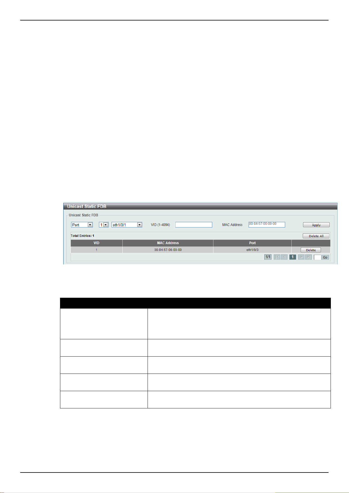
DGS-1510 Series Gigabit Ethernet SmartPro Switch Web UI Reference Guide
Parameter
Description
Port / Drop
Allows the selection of the port number on which the MAC address
entered resides. This option could also drop the MAC address from
the unicast static FDB. When selecting Port, select the switch unit
and port number.
Unit Number
Select the switch unit that will be used for this configuration here,
when Port is selected in the previous drop-down list.
Port Number
Select the port number used here, when Port is selected in the
previous drop-down list.
VID
Enter the VLAN ID on which the associated unicast MAC address
resides.
MAC Address
Enter the MAC address to which packets will be statically forwarded
or dropped. This must be a unicast MAC address.
5. Layer 2 Features
FDB
VLAN
Spanning Tree
ERPS (G.8032)
Loopback Detection
Link Aggregation
L2 Multicast Control
LLDP
FDB
Static FDB
Unicast Static FDB
This window is used to view and configure the static unicast forwarding settings on the Switch.
To view the following window, click L2 Features > FDB > Static FDB > Unicast Static FDB, as
shown below:
Figure 5-1 Unicast Static FDB window
The fields that can be configured are described below:
Click the Apply button to accept the changes made.
Click the Delete All button to delete all the entries found in the display table.
Click the Delete button to remove the specified entry.
Enter a page number and click the Go button to navigate to a specific page when multiple pages exist.
83
Page 92

DGS-1510 Series Gigabit Ethernet SmartPro Switch Web UI Reference Guide
Parameter
Description
Unit
Select the switch unit that will be used for this configuration here.
From Port / To Port
Select the appropriate port range used for the configuration here.
VID
Enter the VLAN ID of the VLAN the corresponding MAC address
belongs to.
MAC Address
Enter the static destination MAC address of the multicast packets.
This must be a multicast MAC address. The format of the
destination MAC address is 01-XX-XX-XX-XX-XX.
Parameter
Description
Aging Time
Enter the MAC address table’s aging time value here. This value
must be between 10 and 1000000 seconds. Entering 0 will disable
MAC address aging. By default, this value is 300 seconds.
Aging Destination Hit
Select to enable or disable the aging destination hit function.
Multicast Static FDB
This window is used to view and configure the multicast static FDB settings.
To view the following window, click L2 Features > FDB > Static FDB > Multicast Static FDB, as
shown below:
Figure 5-2 Multicast Static FDB window
The fields that can be configured are described below:
Click the Apply button to accept the changes made.
Click the Delete All button to remove all the entries.
Click the Delete button to remove the specific entry.
Enter a page number and click the Go button to navigate to a specific page when multiple pages exist.
MAC Address Table Settings
This window is used to view and configure the MAC address table’s global settings.
To view the following window, click L2 Features > FDB > MAC Address Table Settings, as shown
below:
Figure 5-3 MAC Address Table Settings (Global Settings) window
The fields that can be configured are described below:
Click the Apply button to accept the changes made.
84
Page 93

DGS-1510 Series Gigabit Ethernet SmartPro Switch Web UI Reference Guide
Parameter
Description
Unit
Select the switch unit that will be used for this configuration here.
From Port / To Port
Select the range of ports that will be used for this configuration here.
State
Select to enable or disable the MAC address learning function on
the ports specified here.
After clicking the MAC Address Learning tab, at the top of the page, the following page will be
available.
Figure 5-4 MAC Address Table Settings (MAC Address Learning) window
The fields that can be configured are described below:
Click the Apply button to accept the changes made.
MAC Address Table
This window is used to view the entries listed in the MAC address table.
To view the following window, click L2 Features > FDB > MAC Address Table, as shown below:
Figure 5-5 MAC Address Table window
The fields that can be configured are described below:
85
Page 94

DGS-1510 Series Gigabit Ethernet SmartPro Switch Web UI Reference Guide
Parameter
Description
Port
Select the switch unit and the port that will be used for this
configuration here.
VID
Enter the VLAN ID that will be used for this configuration here.
MAC Address
Enter the MAC address that will be used for this configuration here.
Parameter
Description
MAC Address Notification
Select to enable or disable MAC notification globally on the Switch.
Interval
Enter the time value between notifications. This value must be
between 1 and 2147483647 seconds. By default, this value is 1
Click the Clear Dynamic by Port button to clear the dynamic MAC address listed on the
corresponding port.
Click the Clear Dynamic by VLAN button to clear the dynamic MAC address listed on the
corresponding VLAN.
Click the Clear Dynamic by MAC button to clear the dynamic MAC address entered.
Click the Find button to locate a specific entry based on the information entered.
Click the Clear All button to clear all dynamic MAC addresses.
Click the View All button to display all the MAC addresses recorded in the MAC address table.
Enter a page number and click the Go button to navigate to a specific page when multiple pages exist.
MAC Notification
This window is used to view and configure MAC notification.
To view the following window, click L2 Features > FDB > MAC Notification, as shown below:
Figure 5-6 MAC Notification (MAC Notification Settings) window
The fields that can be configured are described below:
86
Page 95

DGS-1510 Series Gigabit Ethernet SmartPro Switch Web UI Reference Guide
second.
History Size
Enter the maximum number of entries listed in the history log used
for notification. This value must be between 0 and 500. By default,
this value is 1.
MAC Notification Trap State
Select this option to enable or disable the MAC notification trap
state.
Unit
Select the switch unit that will be used for this configuration here.
From Port / To Port
Select the range of ports that will be used for this configuration
here.
Added Trap
Select this option to enable or disable the added trap for the port(s)
selected.
Removed Trap
Select this option to enable or disable the removed trap for the
port(s) selected.
Parameter
Description
VID List
Enter the VLAN ID list that will be created here.
Click the Apply button to accept the changes made for each individual section.
After clicking the MAC Notification History tab, the following page will be available.
A list of MAC notification messages will be displayed.
VLAN
802.1Q VLAN
This window is used to view and configure the VLAN settings on this switch.
To view the following window, click L2 Features > VLAN > 802.1Q VLAN, as shown below:
Figure 5-7 MAC Notification (MAC Notification History) window
Figure 5-8 802.1Q VLAN window
The fields that can be configured for 802.1Q VLAN are described below:
87
Page 96

DGS-1510 Series Gigabit Ethernet SmartPro Switch Web UI Reference Guide
Parameter
Description
VID
Enter the VLAN ID that will be displayed here.
Parameter
Description
Profile ID
Enter the profile ID that will be created here.
Frame Type
Select the frame type here. Options to choose from are Ethernet2,
SNAP and LLC.
Ether Type
Enter the Ethernet type in hexadecimal form.
Click the Apply button to accept the changes made.
Click the Delete button to remove the specific entry.
The fields that can be configured for Find VLAN are described below:
Click the Find button to locate a specific entry based on the information entered.
Click the View All button to locate all the entries.
Click the Edit button to re-configure the specific entry.
Enter a page number and click the Go button to navigate to a specific page when multiple pages exist.
802.1v Protocol VLAN
Protocol VLAN Profile
This window is used to view and configure the Protocol VLAN profile.
To view the following window, click L2 Features > VLAN > 802.1v Protocol VLAN > Protocol VLAN
Profile, as shown below:
Figure 5-9 9 Protocol VLAN Profile window
The fields that can be configured are described below:
Click the Apply button to accept the changes made.
Click the Delete button to remove the specified entry.
Protocol VLAN Profile Interface
This window is used to view and configure the Protocol VLAN profile interface.
To view the following window, click L2 Features > VLAN > 802.1v Protocol VLAN > Protocol VLAN
Profile Interface, as shown below:
88
Page 97

DGS-1510 Series Gigabit Ethernet SmartPro Switch Web UI Reference Guide
Parameter
Description
Port
Select the switch unit and the port that will be used for this
configuration here.
Profile ID
Select the ID of the protocol group.
VID
Enter the VLAN ID of the Protocol VLAN.
Priority
Select the priority of the Protocol VLAN.
Parameter
Description
Global GVRP State
Select this option to enable or disable the global GVRP state here.
Dynamic VLAN Creation
Select this option to enable or disable the dynamic VLAN creation
function here.
Figure 5-10 Protocol VLAN Profile Interface window
The fields that can be configured are described below:
Click the Apply button to accept the changes made.
Click the Delete button to remove the specified entry.
GVRP
GVRP Global
This window is used to view and configure the GARP VLAN Registration Protocol (GVRP) global
settings.
To view the following window, click L2 Features > VLAN > GVRP > GVRP Global, as shown below:
The fields that can be configured are described below:
Figure 5-11 GVRP Global window
Click the Apply button to accept the changes made.
GVRP Port
This window is used to view and configure the GVRP port settings.
To view the following window, click L2 Features > VLAN > GVRP > GVRP Port, as shown below:
89
Page 98

DGS-1510 Series Gigabit Ethernet SmartPro Switch Web UI Reference Guide
Parameter
Description
Unit
Select the switch unit that will be used for this configuration here.
From Port / To Port
Select the appropriate port range used for the configuration here.
GVRP Status
Select this option to enable or disable the GVRP port status. This
enables the port to dynamically become a member of a VLAN. By
default, this option is disabled.
Join Time
Enter the Join Time value in centiseconds. This value must be
between 10 and 10000 centiseconds. By default, this value is 20
centiseconds.
Leave Time
Enter the Leave Time value in centiseconds. This value must be
between 10 and 10000 centiseconds. By default, this value is 60
centiseconds.
Leave All Time
Enter the Leave All Time value in centiseconds. This value must be
between 10 and 10000 centiseconds. By default, this value is 1000
centiseconds.
Figure 5-12 GVRP Port window
The fields that can be configured are described below:
Click the Apply button to accept the changes made.
GVRP Advertise VLAN
This window is used to view and configure the GVRP advertised VLAN settings.
To view the following window, click L2 Features > VLAN > GVRP > GVRP Advertise VLAN, as
shown below:
90
Page 99

DGS-1510 Series Gigabit Ethernet SmartPro Switch Web UI Reference Guide
Parameter
Description
Unit
Select the switch unit that will be used for this configuration here.
From Port / To Port
Select the appropriate port range used for the configuration here.
Action
Select the advertised VLAN to port mapping action that will be taken
here. Options to choose from are All, Add, Remove and Replace.
When selecting All, all the advertised VLANs will be used.
Advertise VID List
Enter the advertised VLAN ID list here.
Figure 5-13 GVRP Advertise VLAN window
The fields that can be configured are described below:
Click the Apply button to accept the changes made.
GVRP Forbidden VLAN
This window is used to view and configure the GVRP forbidden VLAN settings.
To view the following window, click L2 Features > VLAN > GVRP > GVRP Forbidden VLAN, as
shown below:
91
Page 100

DGS-1510 Series Gigabit Ethernet SmartPro Switch Web UI Reference Guide
Parameter
Description
Unit
Select the switch unit that will be used for this configuration here.
From Port / To Port
Select the appropriate port range used for the configuration here.
Action
Select the forbidden VLAN to port mapping action that will be taken
here. Options to choose from are All, Add, Remove and Replace.
When selecting All, all the forbidden VLANs will be used.
Forbidden VID List
Enter the forbidden VLAN ID list here.
Figure 5-14 GVRP Forbidden VLAN window
The fields that can be configured are described below:
Click the Apply button to accept the changes made.
GVRP Statistics Table
This window is used to display GVRP statistics information.
To view the following window, click L2 Features > VLAN > GVRP > GVRP Statistics Table, as
shown below:
92
 Loading...