

D-Link DGS-1210-12TS/ME, DGS-1210, DGS-1210-28/ME, DGS-1210-20/ME, DGS-1210-10/ME User Manual
...
User Manual
Product Model : DGS-1210/ME Series
Metro Ethernet Switches
Release 2.10
©Copyright 2016. All rights reserved.

Table of Contents DGS-1210 series Metro Ethernet Managed Switch User Manual
Table of Contents
Table of Contents ............................................................................................................................................. i
About This Guide ............................................................................................................................................. 1
Terms/Usage .................................................................................................................................................. 1
Copyright and Trademarks ............................................................................................................................ 1
1 Product Introduction ................................................................................................................................... 2
Switch Description .......................................................................................................................................... 2
Front Panel Description.................................................................................................................................. 2
LED Indicators ................................................................................................................................................ 6
Rear Panel Description .................................................................................................................................. 8
Side Panel Description ................................................................................................................................. 10
Gigabit Fiber Por ts ....................................................................................................................................... 10
Connecting the DP S-200A/500A/500DC to the RPS Por t (for DGS-1210-10/12TS/20/28/28X/28XS/52/ME
only).............................................................................................................................................................. 11
Installing the RPS into a Rack-mount Chassis (for DGS-1210-10/12TS/20/28/28X/28XS/52/ME only) ..... 12
DPS-800 Rack-mount Chassis ................................................................................................................. 12
2 Hardware Installation ................................................................................................................................ 13
Step 1: Unpacking ........................................................................................................................................ 13
Step 2: Switch Installation ............................................................................................................................ 13
Desktop or Shelf Installation ..................................................................................................................... 13
Rack Installation ....................................................................................................................................... 13
Step 3 – Plugging in the AC Power Cord ..................................................................................................... 14
Power Failure ........................................................................................................................................... 15
3 Getting Started ........................................................................................................................................... 16
Management Options ................................................................................................................................... 16
Using Web-based Management Interface ................................................................................................... 16
Supported Web Browsers ........................................................................................................................ 16
Connecting to the Switch .......................................................................................................................... 16
Accessing the Web-based Management Interface .................................................................................. 17
Web-based Management ............................................................................................................................. 17
D-Link Network Assistant (DNA) .................................................................................................................. 17
4 Configuration ............................................................................................................................................. 19
Web-based Management ............................................................................................................................. 19
Tool Bar > Save Menu ................................................................................................................................. 20
Save Configuration ................................................................................................................................... 20
Save Log .................................................................................................................................................. 20
Tool Bar > Tool Menu .................................................................................................................................. 20
Reset System ........................................................................................................................................... 20
Reboot Device .......................................................................................................................................... 21
Configuration Backup & Restore .............................................................................................................. 21
Firmware Backup & Upgrade ................................................................................................................... 22
Flash Information ...................................................................................................................................... 23
Tool Bar > Online Help ................................................................................................................................. 23
Function Tree ............................................................................................................................................... 23
Device Information.................................................................................................................................... 24
System > System Settings ....................................................................................................................... 24
System > Firmware Information ............................................................................................................... 25
System > Serial Port Settings................................................................................................................... 26
System > IP Interface ............................................................................................................................... 26
ii

Table of Contents DGS-1210 series Metro Ethernet Managed Switc h User Manual
System > Static ARP Settings .................................................................................................................. 27
System > IPv6 System Settings ............................................................................................................... 27
System > IPv6 Neighbor Settings ............................................................................................................ 28
System > DHCP Auto Configuration ........................................................................................................ 29
System > DHCP Auto Image .................................................................................................................... 29
System > Port Configuration > Port Settings ........................................................................................... 29
System > Port Configuration > Port Description ...................................................................................... 30
System > Port Configuration > Port Error Disabled ................................................................................. 30
System > Port Configuration > Port Media Type ...................................................................................... 31
System > SNMP Settings > SNMP Global State ..................................................................................... 31
System > SNMP Settings > SNMP User Table ........................................................................................ 31
System > SNMP Settings > SNMP Group Table ..................................................................................... 32
System > SNMP Settings > SNMP View Table ....................................................................................... 33
System > SNMP Settings > SNMP Community Table ............................................................................. 33
System > SNMP Settings > SNMP Host Table ........................................................................................ 33
System > SNMP Settings > SNMP Engine ID ......................................................................................... 34
System > SNMP Settings > SNMP Trap Settings .................................................................................... 34
System > User Accounts .......................................................................................................................... 35
System > MAC Address Aging Time ........................................................................................................ 35
System > ARP Aging Time Settings ......................................................................................................... 36
System > PPPoE Circuit ID Insertion Settings ......................................................................................... 36
System > Web Settings ............................................................................................................................ 37
System > Telnet Settings ......................................................................................................................... 37
System > Password Encryption................................................................................................................ 37
System > Ping Test .................................................................................................................................. 37
System > MAC Notification Settings ........................................................................................................ 38
System > System Log Configuration > System Log Settings .................................................................. 38
System > System Log Configuration > System Log Server ..................................................................... 39
System > Time Profile .............................................................................................................................. 39
System > Power Saving ........................................................................................................................... 40
System > IEEE802.3az EEE Settings ...................................................................................................... 40
System > SMTP Service > SMTP Server Settings .................................................................................. 41
System > SMTP Service > SMTP Service ............................................................................................... 41
System > D-Link Discover Protocol Settings ............................................................................................ 42
Configuration > Jumbo Frame .................................................................................................................. 43
Configuration > 802.1Q VLAN .................................................................................................................. 43
Configuration > Private VLAN > Private VL AN Sett in g s .......................................................................... 45
Configuration > Private VLAN > Private VL AN T runk .............................................................................. 46
Configuration > VLAN Status ................................................................................................................... 47
Configuration > MAC-Based VLAN Settings ............................................................................................ 48
Configuration > GVRP Settings ................................................................................................................ 48
Configuration > GVRP Timer Settings ..................................................................................................... 49
Configuration > QinQ > QinQ Settings ..................................................................................................... 49
Configuration > QinQ > VLAN Translati on CVID Entry Settings .............................................................. 50
Configuration > Layer 2 Protocol Tunneling Settings ............................................................................... 51
Configuration > 802.1v Protoc ol VL AN > 802.1 v Protocol Group Settings .............................................. 52
Configuration > 802.1v Protoc ol VL AN > 802.1 v Protocol VLAN Settings............................................... 52
Configuration > VLAN Trunk Settings ...................................................................................................... 53
Configuration > Link Aggregation > Port Trunkings ................................................................................. 53
iiii

Table of Contents DGS-1210 series Metro Ethernet Managed Switch User Manual
Configuration > Link Aggregation > LACP Port Settings.......................................................................... 54
Configuration > BPDU Protection Settings ............................................................................................... 54
Configuration > IGMP Snooping > IGMP Snooping ................................................................................. 55
Configuration > IGMP Snooping > IGMP Access Control Settings .......................................................... 57
Configuration > IGMP Snooping > ISM VLAN Settings ........................................................................... 58
Configuration > IGMP Snooping > Host Table ......................................................................................... 59
Configuration > IGMP Snooping > IP Multicast Profile Settings .............................................................. 59
Configuration > IGMP Snooping > Limited Multicast Range Settings ...................................................... 60
Configuration > IGMP Snooping > Max Multicast Group Settings ........................................................... 60
Configuration > IGMP Snooping > IGMP Snooping Static Group Settings .............................................. 61
Configuration > MLD Snooping > MLD Snooping Settings ...................................................................... 62
Configuration > MLD Snooping > MLD Host Table .................................................................................. 63
Configuration > Port Mirroring .................................................................................................................. 63
Configuration > Loopback Detection ........................................................................................................ 63
Configuration > SNTP Settings > Time Settings ...................................................................................... 64
Configuration > SNTP Settings > TimeZone Settings .............................................................................. 65
Configuration > DHCP/BOOTP Relay > DHCP/BOOTP Relay Global Settings ...................................... 66
Configuration > DHCP/BOOTP Relay > DHCP/BOOTP Relay Interface Settings .................................. 67
Configuration > DHCP Local Relay Settings ............................................................................................ 68
Configuration > DHCPv6 Relay Settings .................................................................................................. 68
Configuration > DHCPv6 Relay Option38 Settings .................................................................................. 69
Configuration > Spanning Tree > STP Bridge Global Settings ................................................................ 69
Configuration > Spanning Tree > STP Port Settings ............................................................................... 71
Configuration > Spanning Tree > MST Configuration Identification ......................................................... 72
Configuration > Spanning Tree > STP Instance Settings ........................................................................ 73
Configuration > Spanning Tree > MSTP Port Information ....................................................................... 74
Configuration > Ethernet OAM > Ether net O AM Port S etti ngs ................................................................ 74
Configuration > Ethernet OAM > Ether net O AM Event C onf igura tio n ..................................................... 75
Configuration > DDM > DDM Settings ..................................................................................................... 76
Configuration > DDM > DDM Temperature Threshold Settings .............................................................. 76
Configuration > DDM > DDM Voltage Settings Thr eshold Set tin gs ......................................................... 77
Configuration > DDM > DDM Bias Current Threshold Settings ............................................................... 78
Configuration > DDM > DDM TX Power Threshold Settings ................................................................... 78
Configuration > DDM > DDM RX Power Threshold Settings ................................................................... 79
Configuration > DDM > DDM Status Table .............................................................................................. 79
Configuration > DULD > DULD Global Settings ....................................................................................... 80
Configuration > DULD > DULD Port Settings .......................................................................................... 80
Configuration > Multicast Forwarding & Filtering > Multicast Filtering ..................................................... 80
Configuration > ERPS Setting .................................................................................................................. 81
QoS > Traffic Control ................................................................................................................................ 82
QoS > Bandwidth Control ......................................................................................................................... 83
QoS > CoS Scheduling Mechanism ......................................................................................................... 84
QoS > CoS Output Scheduling ................................................................................................................ 84
QoS > 802.1p Default Priority................................................................................................................... 85
QoS > 802.1p User Priority ...................................................................................................................... 85
QoS > DSCP Priority Settings .................................................................................................................. 86
QoS > Priority Settings ............................................................................................................................. 86
RMON > RMON Basic Settings................................................................................................................ 87
RMON > RMON Ethernet Statistics Configuration ................................................................................... 87
iii

Table of Contents DGS-1210 series Metro Ethernet Managed Switc h User Manual
RMON > RMON History Control Configuration ........................................................................................ 87
RMON > RMON Alarm Configuration ...................................................................................................... 88
RMON > RMON Event Configuration ....................................................................................................... 88
Security > Trusted Host ............................................................................................................................ 89
Security > Safeguard Engine.................................................................................................................... 89
Security > CPU Protect ............................................................................................................................ 89
Security > Gratuitous ARP ....................................................................................................................... 90
Security > Port Security ............................................................................................................................ 91
Security > SSL Settings ............................................................................................................................ 91
Security > Smart Binding > Smart Binding Settings ................................................................................. 92
Security > Smart Binding > Smart Binding ............................................................................................... 93
Security > Smart Binding > White List ...................................................................................................... 94
Security > Smart Binding > Black List ...................................................................................................... 94
Security > Smart Binding > DHCP Snooping List .................................................................................... 95
Security > 802.1X > 802.1X Settings ....................................................................................................... 95
Security > 802.1X > 802.1X User ............................................................................................................. 97
Security > 802.1X > 802.1X Authentication RADIUS ............................................................................... 97
Security > 802.1X > 802.1X Guest VLAN ................................................................................................ 98
Security > MAC Address Table > Static MAC .......................................................................................... 98
Security > MAC Address Table > Dynamic Forwarding Table ................................................................. 99
Security > MAC Address Table > Auto Learning Vlan Settings ............................................................. 100
Security > Access Authentic ation Contr ol > Authentication Policy Settings .......................................... 100
Security > Access Authentication Control > Application Authentication Settings .................................. 100
Security > Access Authentication Control > Authentication Server Group ............................................ 101
Security > Access Authentication Control > Authentication Server ....................................................... 102
Security > Access Authentic ation Contr ol > Login Met hod Lists ............................................................ 103
Security > Access Authenti c ation Contr ol > Enabl e Me thod Lis ts ......................................................... 103
Security > Access Authentic ation Contr ol > Local Ena ble Password Settings ...................................... 104
Security > Traffic Segmentation ............................................................................................................. 104
Security > DoS Prevention Settings ....................................................................................................... 105
Security > DHCP Server Screening > DHCP Server Screening Port Settings ...................................... 105
Security > DHCP Server Screening > DHCP Server Screening Vlan Settings...................................... 106
Security > DHCP Ser ver Scr eeni ng > Filter DHC P Serv er .................................................................... 106
Security > DHCP Server Screening > Filter DH CP v 6 Server ................................................................ 106
Security > DHCP Server Screening > Filter ICMPv6 ............................................................................. 107
Security > SSH Settings > SSH Settings ............................................................................................... 108
Security > SSH Settings > SSH Authmode and Algorithm Settings ...................................................... 109
Security > SSH Settings > SSH User Authentication Lists .................................................................... 110
Security > MAC-based Access Control (MAC) > MAC-based Access Control Settings ........................ 110
Security > MAC-based Access Control (MAC) > MAC-based Access Control Local Settings .............. 111
Security > MAC-based Access Control (MAC) > MAC-based Access Control Authentication State .... 112
Monitoring > Statistics ............................................................................................................................ 112
Monitoring > Session Table .................................................................................................................... 113
Monitoring > CPU Utilization .................................................................................................................. 113
Monitoring > Memory Utilizatio n ............................................................................................................. 114
Monitoring > Port Utilization ................................................................................................................... 114
Monitoring > Packet Size ........................................................................................................................ 115
Monitoring > Packets > Transmitted (TX) .............................................................................................. 116
Monitoring > Packets > Received (RX) .................................................................................................. 117
iivv

Table of Contents DGS-1210 series Metro Ethernet Managed Switch User Manual
Monitoring > Packets > UMB Cast (RX) ................................................................................................. 118
Monitoring > Errors > Received (RX) ..................................................................................................... 119
Monitoring > Errors > Transmitted (TX).................................................................................................. 120
Monitoring > Cable Diagnostics ............................................................................................................. 122
Monitoring > System Log ........................................................................................................................ 122
Monitoring > Browse ARP Table ............................................................................................................ 123
Monitoring > Ethernet OAM > Browse Ether net O AM E vent Log .......................................................... 123
Monitoring > Ethernet OAM > Browse Ether net O AM S tatist ic s ............................................................ 124
Monitoring > IGMP Snooping > IGMP Snooping Group ........................................................................ 124
Monitoring > IGMP Snooping > IGMP Snooping Host ........................................................................... 124
Monitoring > MLD Snooping > MLD Snooping Group ............................................................................ 125
Monitoring > Port Access Control > RADIU S Authentication ................................................................. 125
Monitoring > Port Access Control > RADIU S Acc oun t Cli ent ................................................................ 126
Monitoring > sFlow > sFlow Global Settings .......................................................................................... 127
Monitoring > sFlow > sFlow Analyzer Server Settings ........................................................................... 128
Monitoring > sFlow > sFlow Flow Sampler Settings .............................................................................. 129
Monitoring > sFlow > sFlow Counter Poller Settings ............................................................................. 129
ACL > ACL Configuration W izard ........................................................................................................... 130
ACL > Access Profile List ....................................................................................................................... 131
ACL > ACL Finder .................................................................................................................................. 132
ACL > CPU Filter Configuration Wizard ................................................................................................. 132
ACL > CPU Filter Access Profile List ..................................................................................................... 133
ACL > CPU Filter Finder ......................................................................................................................... 134
ACL > ACL Flow Meter ........................................................................................................................... 134
PoE > PoE Port Settings (DGS-1210-10P/28P/28MP/52P/52MP/52MPP/ME only) ............................. 136
PoE > PoE System Settings (DGS-1210-10P/28P/28MP/52P/52MP/52MPP/ME only) ........................ 138
Time-Based PoE > Time Range Settings .............................................................................................. 138
LLDP > LLDP Global Settings ................................................................................................................ 139
LLDP > Basic LLDP Port Settings .......................................................................................................... 139
LLDP > 802.1 Extension LLDP Port Settings ......................................................................................... 140
LLDP > 802.3 Extension LLDP Port Settings ......................................................................................... 141
LLDP > LLDP Management Address Settings ....................................................................................... 141
LLDP > LLDP Statistics Table ................................................................................................................ 142
LLDP > LLDP Management Address Table ........................................................................................... 143
LLDP > LLDP Local Port Table .............................................................................................................. 143
LLDP > LLDP Remote Port Table .......................................................................................................... 144
LLDP > LLDP-MED Settings .................................................................................................................. 146
L3 Functions > IPv4 Static Route ........................................................................................................... 146
L3 Functions > IPv4 Routing Table Finder ............................................................................................. 147
L3 Functions > IPv6 Static Route ........................................................................................................... 147
L3 Functions > IPv6 Routing Table Finder ............................................................................................. 148
Appendix A - Ethernet Technology ............................................................................................................ 149
Gigabit Ethernet Technology ..................................................................................................................... 149
Fast Ethernet Technology .......................................................................................................................... 149
Switching Technology ................................................................................................................................ 149
Appendix B - Ethernet Technology ............................................................................................................ 150
Features ..................................................................................................................................................... 150
L2 Features ............................................................................................................................................ 150
VLAN ...................................................................................................................................................... 150
v

Table of Contents DGS-1210 series Metro Ethernet Managed Switc h User Manual
L3 Features ............................................................................................................................................ 150
QoS (Quality of Service) ......................................................................................................................... 150
Security ................................................................................................................................................... 151
OAM ....................................................................................................................................................... 151
Management ........................................................................................................................................... 151
vvii

About This Guide DGS-1210 series Metro Ethernet Managed Switch User Manual
ased may
formation about your switch, its
About This Guide
This guide provides step-by-step instructions on how install the D-Link DGS-1210/ME Metro Ethernet
Switches, how to use the Web Utility, and how to perform web-based management functions.
Note: The model you have purch
appear slightly different from the illustrations
shown in the document. Refer to the Product
Instruction and Technical Specification sections
for detailed in
components, network connections, and technica l
specifications.
This guide is mainly divided into three parts:
1. Hardware Installation: Ste p -by-step hardware installation procedures.
2. Getting Started: A startup guide for basic switch installation and settings.
3. Configuration: Information about the function descriptions and configuration settings.
Terms/Usage
In this guide, the term “Switch” (first letter capitalized) refers to DGS-1210/ME Metro Ether net Switch, and
“switch” (first letter lo wer case) ref ers to other Ethern et switches. Som e technologies refer to term s “switch”,
“bridge” and “switching hubs” interchangeably, and both are commonly accepted for Ethernet switches.
A NOTE indicates important information that
helps a better use of the device.
A CAUTION indicates pote ntial prop erty dam age
or personal injury.
Copyright and Trademarks
Information in this document is subjected to change without notice.
© 2016 D-Link Corporation. All rights reserved.
Reproduction in any manner whatsoever without the written permission of D-Link Corporation is strictly
forbidden.
Trademarks used in th is text: D-Link and the D-LIN K logo are trademark s of D-Link Corporation; Micros oft
and Windows are registered trademarks of Microsoft Corporation.
Other trademarks and trade names ma y be used in this document to refer to either the entities cla iming the
marks and names or their products. D-Link Corporation discl aims an y proprietary interest i n trademark s and
trade names other than its own.
1
1 Product Introduction DGS-1210 series Metro Ethernet Managed Switch User Manual
1 Product Introduction
Switch Description
Front Panel Description
LED Indicators
Rear Panel Description
Side Panel Description
Connecting the DPS-200A/500A/500DC to the RPS Port (for DGS-1210-
10/12TS/20/28X/28XS/52/ME only)
Installing the RPS into the Rack-mount Chassis (for DGS-1210-10/12TS/20/28X/28XS/52/ME only)
Switch Description
The DGS-1210/ME Metro Ethernet Switch is equipped with Copper ports (10/100/1000Mbps) and SFP
ports (1000Mbps) that can be used to attach various networking devices to the network like Computers,
Notebooks, Print Servers, Network Attached Storage devices, IP Cam eras, VoIP PBX devices, and other
Switches. The Sm all Form Factor Portable (SFP) ports can be used t oget her with fiber-optical transc ei vers in
order to connect various other n etworking devices , using a fiber-op tic connection , to the network at Gigabit
Ethernet speeds over great distances.
This DGS-1210/ME Metro Ethernet Switch provides unsurpassed performance, fault tolera nce, scalability,
robust security, standard-based interoperabilit y and impressive technolog y to future-proof departm ental and
enterprise network deployments.
It allows IGMP Snooping a nd Authentication, QoS, B andwidth Control, ACL and many security functions. It
can be managed by Web UI, or commands via Telnet.
The DGS-1210/ME Metro Ether net Switches have different port configuration (10/100/1000Base-T or SFP
ports) that ma y be used in to uplink var ious network devices to the Switch, including PCs , hubs and other
switches to provide a gigabit Ethernet uplink in full-duplex mode. The SFP (Small Form Factor Portable)
ports are used with fiber-o ptical transceiver c abling in order to up link various other net working devices f or a
gigabit link that may span great distances.
Front Panel Description
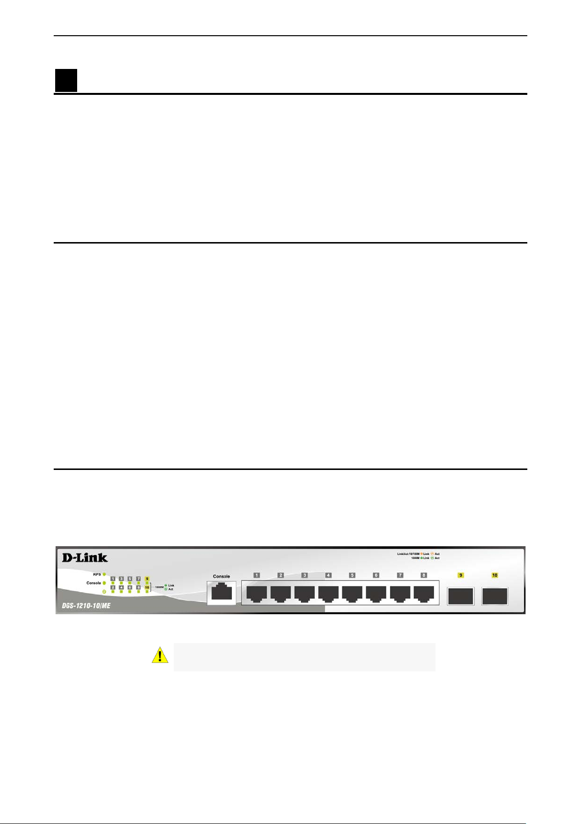
The front panel of the DGS-1210-10/ME switch consists out of the following:
• 8 10/100/1000Mbps Copper Ports
• 2 1000Mbps SFP ports
• One RJ-45 Console Port
• LEDs for Power, Console, RPS, Link/Act for port 1 ~ 10
Figure 1.1 – DGS-1210-10/ME Fron t Panel
CAUTION: The MiniGBIC ports should use UL listed
Optical Transceiver product, Rated Laser Class I. 3.3Vdc.
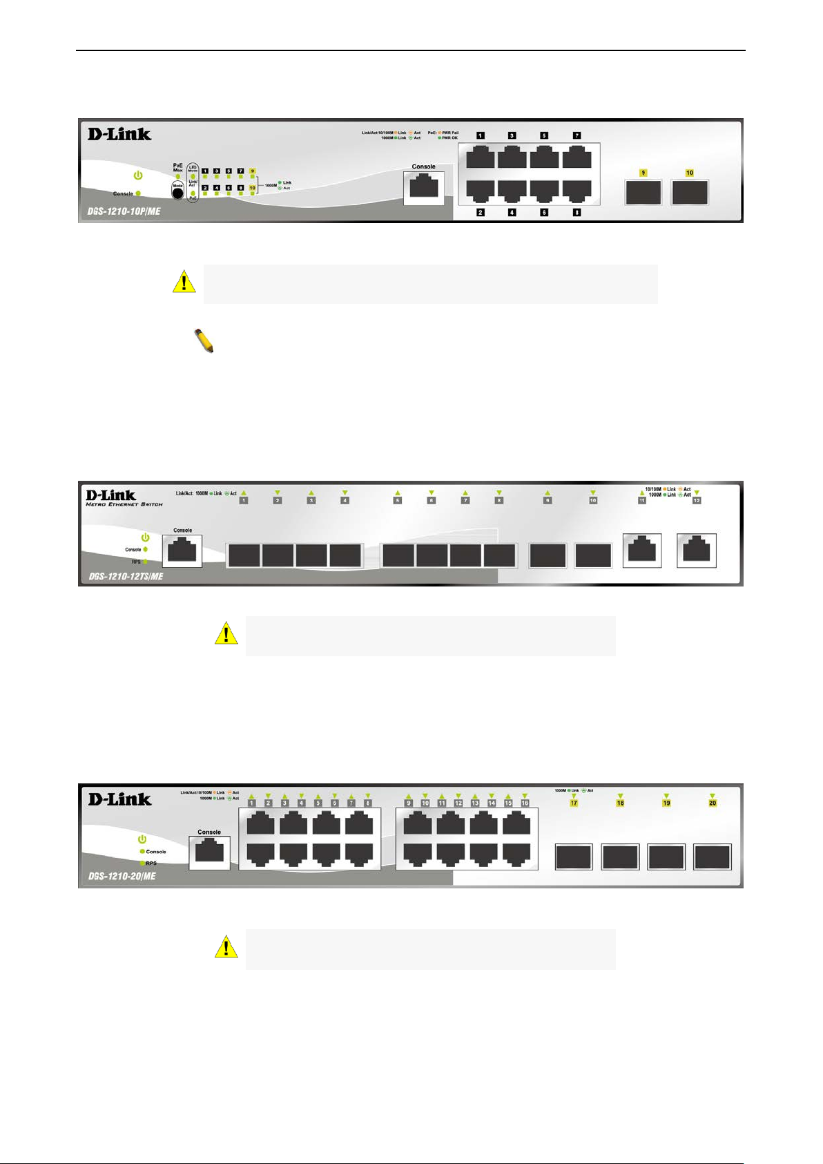
The front panel of the DGS-1210-10P/ME switch consists out of the following:
• 8 10/100/1000Mbps Copper Ports
• 2 1000Mbps SFP ports
• One RJ-45 Console Port
• LEDs for Power, PoE Max, Console, Link/Act for port 1 ~ 10
2
1 Product Introduction DGS-1210 series Metro Ethernet Managed Switch User Manual
listed Optical
NOTE: The power budget is 78 Watts for DGS-1210-10P/ME.
• Mode: By pressing the Mode button, the Port LED will switch between Link/Act and PoE modes.
Figure 1.2 – DGS-1210-10P/ME Front Panel
CAUTION: The MiniGBIC ports should use UL
Transceiver product, Rated Laser Class I. 3.3Vdc.
The front panel of the DGS-1210-12TS/ME switch consists out of the following:
• 10 1000Mbps SFP port
• 2 10/100/1000Mbps Copper Ports
• One RJ-45 Console Port
• LEDs for Power, Console, RPS, Link/Act for port 1 ~ 12
Figure 1.3 – DGS-1210-12TS/ME Front Panel
CAUTION: The MiniGBIC ports should use UL listed
Optical Transceiver product, Rated Laser Class I. 3.3Vdc.
The front panel of the DGS-1210-20/ME switch consists out of the following:
• 16 10/100/1000Mbps Copper Ports
• 4 1000Mbps SFP ports
• One RJ-45 Console Port
• LEDs for Power, Console, RPS, Link/Act for port 1 ~ 20
Figure 1.4 – DGS-1210-20/ME Front Panel
CAUTION: The MiniGBIC ports should use UL listed
Optical Transceiver product, Rated Laser Class I. 3.3Vdc.
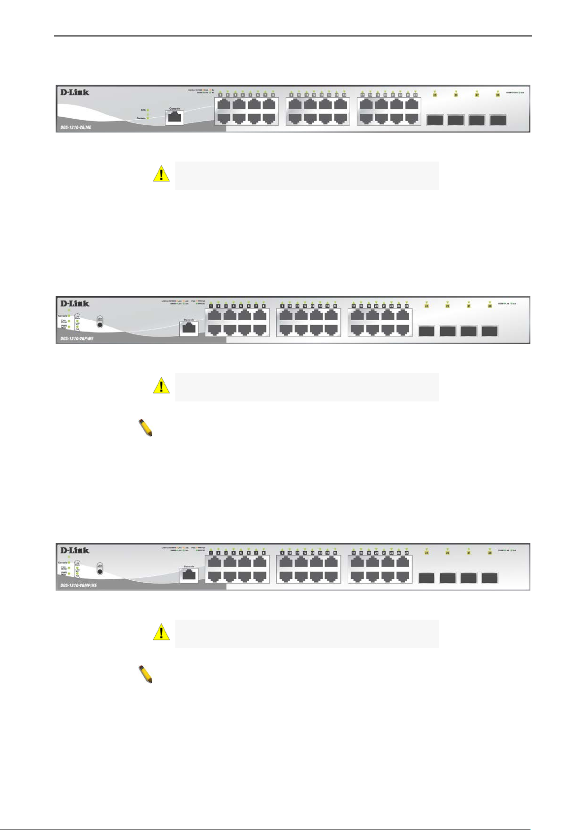
The front panel of the DGS-1210-28/ME switch consists out of the following:
• 24 10/100/1000Mbps Copper Ports
• 4 1000Mbps SFP ports
• One RJ-45 Console Port
33
1 Product Introduction DGS-1210 series Metro Ethernet Managed Switch User Manual
NOTE: The power budget is 193 Watts for DGS-1210-28P/ME.
NOTE: The power budget is 370 Watts for DGS-1210-28MP/ME.
• LEDs for Power, RPS, Console, Link/Act for port 1 ~ 28
Figure 1.5 – DGS-1210-28/ME Front Panel
CAUTION: The MiniGBIC ports should use UL listed
Optical Transceiver product, Rated Laser Class I. 3.3Vdc.
The front panel of the DGS-1210-28P/ME switch consists out of the following:
• 24 10/100/1000Mbps Copper Ports
• 4 1000Mbps SFP ports
• One RJ-45 Console Port
• LEDs for Power, Console, Fan Error, Pwr Max, Link/Act for port 1 ~ 28
• Mode: By pressing the Mode button, the Port LED will switch between Link/Act and PoE modes
Figure 1.6 – DGS-1210-28P/ME Front Panel
CAUTION: The MiniGBIC ports should use UL listed
Optical Transceiver product, Rated Laser Class I. 3.3Vdc.
The front panel of the DGS-1210-28MP/ME switch consists out of the following:
• 24 10/100/1000Mbps Copper Ports
• 4 1000Mbps SFP port
• One RJ-45 Console Port
• LEDs for Power, Console, Fan Error, Pwr Max, Link/Act for port 1 ~ 28
• Mode: By pressing the Mode button, the Port LED will switch between Link/Act and PoE modes
Figure 1.7 – DGS-1210-28MP/M E Front Panel
CAUTION: The MiniGBIC ports should use UL listed
Optical Transceiver product, Rated Laser Class I. 3.3Vdc.
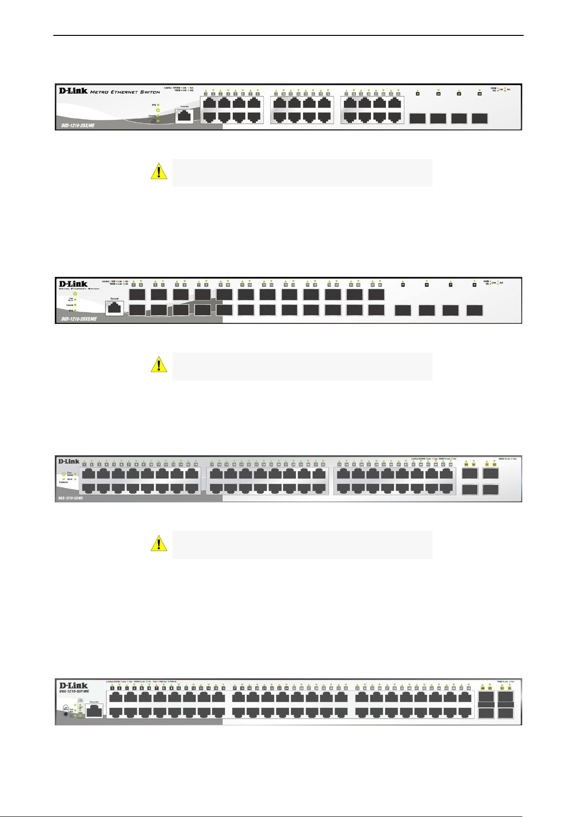
The front panel of the DGS-1210-28X/ME switch consists out of the following:
• 24 10/100/1000Mbps Copper Ports
• 4 1000Mbps/10G SFP+ port
• One RJ-45 Console Port
4
1 Product Introduction DGS-1210 series Metro Ethernet Managed Switch User Manual
• LEDs for RPS, Power, Console, Fan Error, Link/Act for port 1 ~ 28
Figure 1.8 – DGS-1210-28X/ME Front Panel
CAUTION: The MiniGBIC ports should use UL listed
Optical Transceiver product, Rated Laser Class I. 3.3Vdc.
The front panel of the DGS-1210-28XS/ME switch consists out of the following:
• 24 100/1000Mbps SFP port
• 4 1000Mbps/10G SFP+ ports
• One RJ-45 Console Port
• LEDs for Power, Console, Fan Error, RPS, Link/Act for port 1 ~ 28
Figure 1.9 – DGS-1210-28XS/ME Front Panel
CAUTION: The MiniGBIC ports should use UL listed
Optical Transceiver product, Rated Laser Class I. 3.3Vdc.
The front panel of the DGS-1210-52/ME switch consists out of the following:
• 48 10/100/1000Mbps Copper Ports
• 4 1000Mbps SFP ports
• LEDs for Power, Console, Fan Error , RPS, Link/Act for port 1 ~ 52
Figure 1.10 – DGS-1210-52/ME Front Panel
CAUTION: The MiniGBIC ports should use UL listed
Optical Transceiver product, Rated Laser Class I. 3.3Vdc.
The front panel of the DGS-1210-52P/ME switch consists out of the following:
• 48 10/100/1000Mbps Copper Ports
• 24 10/100/1000Mbps PoE ports
• 4 1000Mbps SFP ports
• One RJ-45 Console Port
• LEDs for Power, Console, Fan Error, PoE Max, Link/Act for port 1 ~ 52
• Mode: By pressing the Mode button, the Port LED will switch between Link/Act and PoE modes
Figure 1.11 – DGS-1210-52P/ME Front Panel
55

1 Product Introduction DGS-1210 series Metro Ethernet Managed Switch User Manual
listed Optical
NOTE: The power budget is 193 Watts for DGS-1210-52P/ME.
listed Optical
NOTE: The power budget is 370 Watts for DGS-1210-52MP/ME.
listed Optical
NOTE: The power budget is 740 Watts for DGS-1210-52MPP/ME.
CAUTION: The MiniGBIC ports should use UL
Transceiver product, Rated Laser Class I. 3.3Vdc.
The front panel of the DGS-1210-52MP/ME switch consists out of the following:
• 48 10/100/1000Mbps Copper and PoE Ports
• 4 1000Mbps SFP ports
• One RJ-45 Console Port
• LEDs for Power, Console, Fan Error, PoE Max, Link/Act for port 1 ~ 52
• Mode: By pressing the Mode button, the Port LED will switch between Link/Act and PoE modes
Figure 1.12 – DGS-1210-52MP/ME Front Panel
CAUTION: The MiniGBIC ports should use UL
Transceiver product, Rated Laser Class I. 3.3Vdc.
The front panel of the DGS-1210-52MPP/ME switch consists out of the following:
• 48 10/100/1000Mbps Copper and PoE Ports
• 4 1000Mbps SFP ports
• One RJ-45 Console Port
• LEDs for Power, Console, Fan Error, PoE Max, Link/Act for port 1 ~ 52
• Mode: By pressing the Mode button, the Port LED will switch between Link/Act and PoE modes
Figure 1.13 – DGS-1210-52MPP/ME Fro n t Panel
CAUTION: The MiniGBIC ports should use UL
Transceiver product, Rated Laser Class I. 3.3Vdc.
LED Indicators
The Switch supports LED indicators for Power, Console, Fan, and Link/Act for each port. The following
shows the LED indicat ors for the DGS-1210/ME Metr o Ethernet Switch along with an explanation of each
indicator.
Figure 1.14 –LED Indicators on DGS-1 210/ME SERIES
6

1 Product Introduction DGS-1210 series Metro Ethernet Managed Switch User Manual
Solid
Light
Light
off
Solid
Light
Light
off
The Pwr/PoE Max LED lights up
In the meantime, no
supported.
When the system power usage
range.
Solid
Light
Light
off
Mbps
Solid
When there is a secure
(or link) at any of the ports.
Blinking
When there is reception or
of data occurring at a 1000Mbps
Ethernet connected port.
Solid
When there is a secure
ports.
Blinking
When there is reception or
10/100Mbps Ethernet connected
port.
Light
off
No link.
Solid
Light
Power feeding
Solid
Light
Error Condition
Solid
Off
No Power feeding
Location LED Indicative Color Status Description
Power on.
Power
Green
Power off.
Console on.
Per Device
Console
Fan Error
(for DGS-1210-28P/ME,
28MP/ME, 28X/ME, 28XS/ME,
52/ME, 52P/ME, 52MP/ME,
52MPP/ME)
Pwr/PoE Max.
(for DGS-1210-10P/ME,
28P/ME, 28MP/ME 52P/ME,
52MP/ME, 52MPP/ME)
RPS
(DGS-1210-
10/12TS/20/28/28X/28XS/52/ME)
Green
Red
Red
Green
Blinking POST is in progress.
Console off.
Solid
light
Solid
light
Light
off
The fan has runtime failure and
is brought offline.
when the total PoE output of
Switch reached or exceeded 71
Watts for DGS-1210-10P/ME,
186 Watts for DGS-121028P/52P/ME, 363 Watts for
DGS-1210-28MP/52MP/ME,
and 733 Watts for DGS-121052MPP/ME.
additional PoE device can be
does not reach the guard band
RPS power on.
RPS power off.
LED Per
10/100/1000
Copper Port
Link/Act
PoE Mode
Green/Amber
Green
Amber
Off
77
Green
Green
Amber
Amber
1000Mbps Ethernet connection
transmission (i.e. Activity—Act)
10/100Mbps Ethernet
connection (or link) at any of the
transmission (i.e. Activity—Act)
of data occurring at a

1 Product Introduction DGS-1210 series Metro Ethernet Managed Switch User Manual
When there is a secure
(or link) at any of the ports.
Blinking
When there is reception or
Mbps
Ethernet connected port.
When there is a secure
(For DGS-1210-28XS/ME only)
Blinking
When there is reception or
only)
Solid
off
Solid
Light
When there is a secure 10Gbps
connection at the port.
Blinking
When there is reception or
port.
When there is a secure
port.
Blinking
When there is reception or
port.
Solid
off
LED Per SFP
Port
LED Per 10G
SFP+ Port
(for DGS-121028X/ME,
28XS/ME)
Link/Act
Link/Act
Green
Amber
Off
Green
Amber
Solid
Green
Green
Solid
Light
Amber
Green
Solid
Light
Amber
1000Mbps Ethernet connection
transmission (i.e. Activity—Act)
of data occurring at a 1000
100Mbps connection at the port.
transmission occurring at the
port. (For DGS-1210-28XS/ME
No link.
transmission occurring at the
1000Mbps connection at the
transmission occurring at the
Off
No link.
Rear Panel Description
The rear panel of the Sw itch conta ins an AC p ower co nnector . The AC po wer co nnec tor is a stan dard threepronged connector th at supports the power c ord. Plug-in the fem ale connector of the prov ided power cord
into this socket, and the male side of the cord into a power outlet. The S w itch a utomatically adjusts its power
setting to any suppl y voltage in the range from 100 to 240 VAC at 50 to 60 Hz. Connect the Kensingtoncompatible securit y lock, at the rear of the switch, to a secur e immovable device. Insert the lock into the
notch and turn the key to secure the lock.
The rear panel also includes an outlet for an optional external power suppl y a nd one RJ-45 console port.
When a power failure occurs, the optional external RPS will immediately and automatically assume the
power supply for the Switch.
DGS-1210-10/ME
Figure 1.15- DGS-1210-10/ME Rear Panel
DGS-1210-10P/ME
Figure 1.16- DGS-1210-10P/ME Rear Panel
8
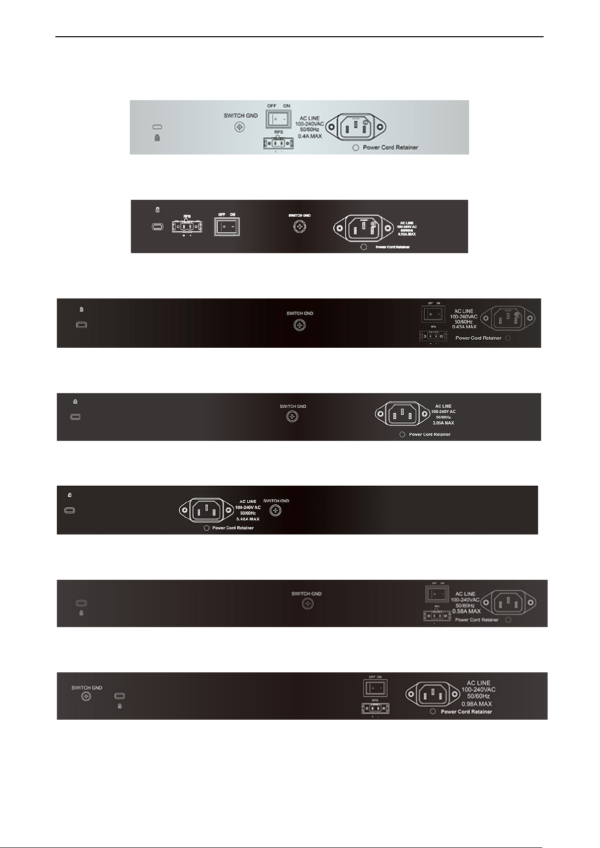
1 Product Introduction DGS-1210 series Metro Ethernet Managed Switch User Manual
DGS-1210-12TS/ME
Figure 1.17- DGS-1210-12TS/ME Rear Panel
DGS-1210-20/ME
Figure 1.18- DGS-1210-20/ME Rear Panel
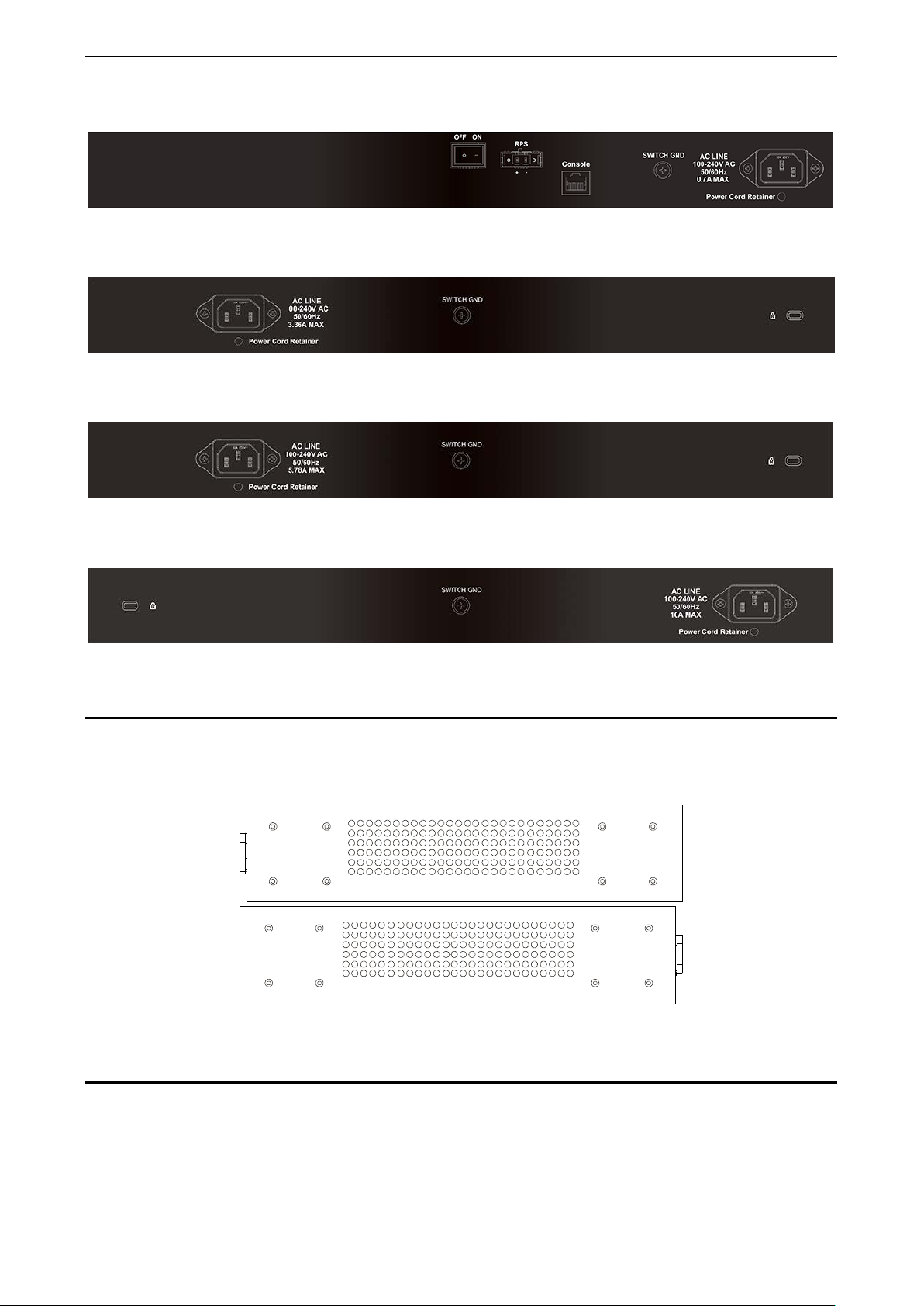
DGS-1210-28/ME
DGS-1210-28P/ME
DGS-1210-28MP/ME
DGS-1210-28X/ME
DGS-1210-28XS/ME
Figure 1.19-DGS-1210-28/ME Rear Panel
Figure 1.20 - DGS-1210-28P/ME Rear Panel
Figure 1.21 -DGS-1210-28MP/ME Rear Panel
Figure 1.22- DGS-1210-28X/ME Rear Panel
Figure 1.23- DGS-1210-28XS/ME Rear Panel
99
1 Product Introduction DGS-1210 series Metro Ethernet Managed Switch User Manual
DGS-1210-52/ME
Figure 1.24 - DGS-1210-52/ME Rear Panel
DGS-1210-52P/ME
Figure 1.25 - DGS-1210-52P/ME Rear Panel
DGS-1210-52MP/ME
Figure 1.26 - DGS-1210-52MP/ME R ear Panel
DGS-1210-52MPP/ME
Figure 1.27 - DGS-1210-52MPP/ME Rear Panel
Side Panel Description
The left- and right-hand panels of the Switch ha ve he at v ents t o d is s ipate heat. Do not block thes e op enings,
and leave at least 6 inches of spac e at the rear and sides of the Switch f or proper ventila tion. Be rem inded
that without proper heat diss ipation and a ir cir culatio n, s ystem components m ight overheat, which c ould lead
to system failure.
Figure 1.28 - Side panels of the DGS-1210/ME SERIES
Gigabit Fiber Ports
The DGS-1210/ME Series f eatures support four Small For m Factor Portable (SF P) ports (opt ional). See the
diagram below to view the four SFP port modules being plugged into the Switch.
10
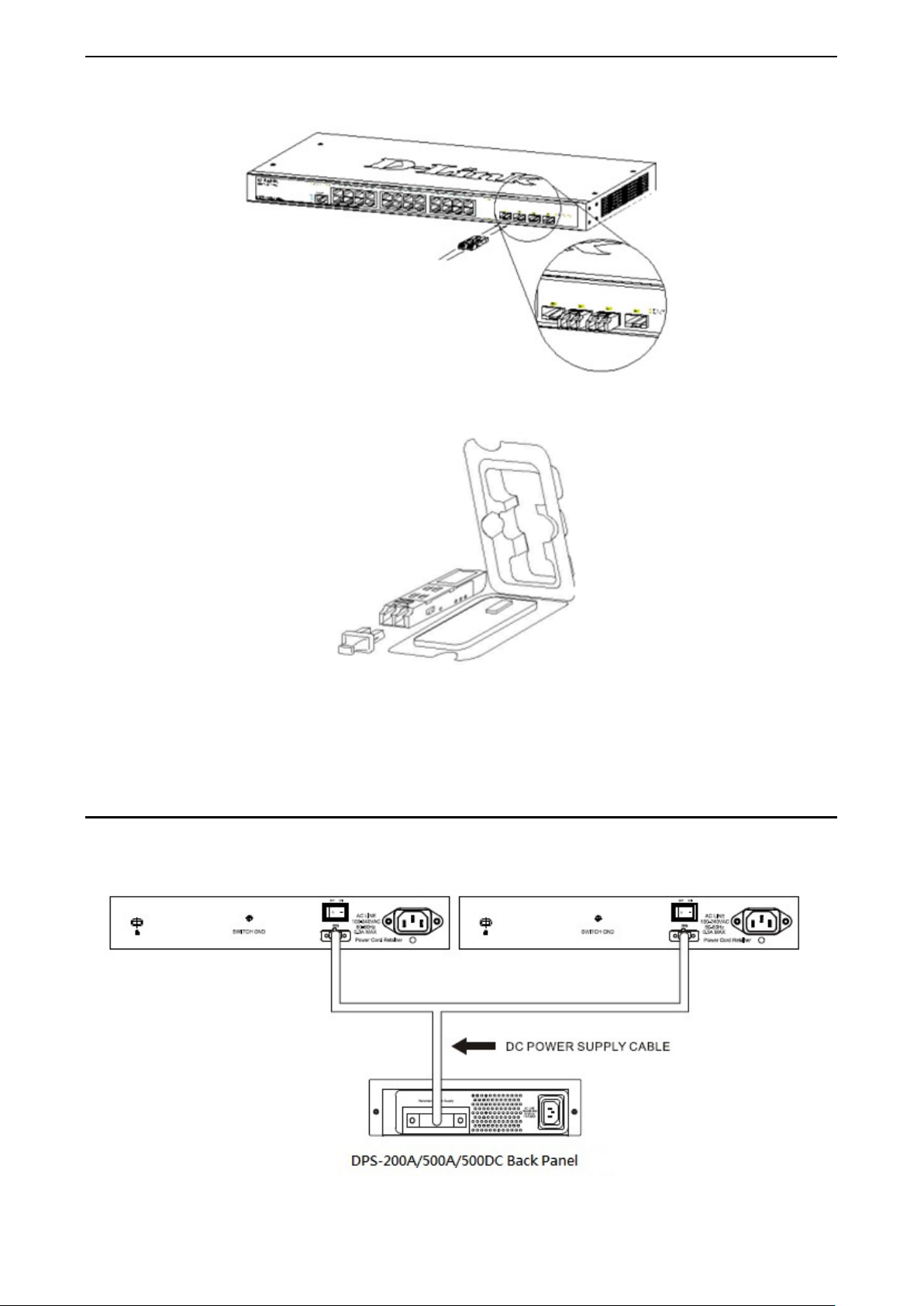
1 Product Introduction DGS-1210 series Metro Ethernet Managed Switch User Manual
Figure 1.29 - Inserting the SFP modules into the Switch
Figure 1.30 - Installing the SFP Module
The Switch is equipped with SF P ports , whic h are to b e used with fib er-optical trans ceiver c abling in order to
uplink various other networking devices for a gigabit link that may span great distances.
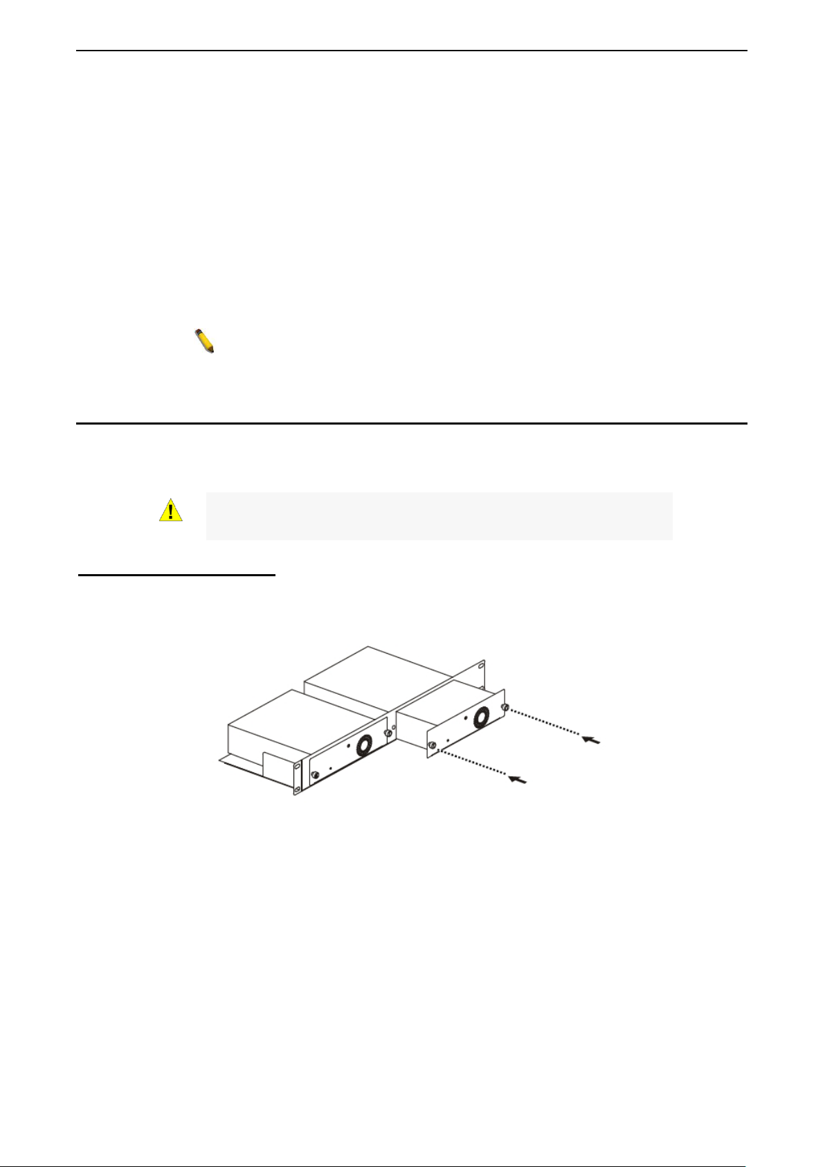
Connecting the DPS-200A/500A/500DC to the RPS Port (for DGS-121010/12TS/20/28/28X/28XS/52/ME only)
The DPS-200A/500A/500DC redundant p ower su pply can be connec ted to the R PS port of the S witch using
the DC power supply cord, called the DPS-CB150-2PS. It is important to notice that the DPS200A/500A/500DC can supply power to one or two DGS-1210-10/ME at the same time.
Figure 1.31 – Connecting two Switches to the DPS-200A/500A/500DC
1111
1 Product Introduction DGS-1210 series Metro Ethernet Managed Switch User Manual
NOTE: See the DPS-200A/500A/500DC Quick Installation Guide for
more information.
CAUTION: DO NOT connect the RPS to the AC power before the DC
power is connected might damage the internal power supply.
The following section explains how to connect the DPS-200A/500A/500DC to the Switch.
• Disconnect the Switch from the main AC power source.
• Insert the 14-pin end of the DPS-CB150-2PS into the DPS-200A/500A/500DC and the 2-pin end into
the receptacle of the RPS port on the Switch.
• Using a standard AC power cord, connec t the DPS-200A/500A/500DC to the main AC po wer sour c e.
A green LED on the front panel of the DPS-200A/500A/500DC will illuminate to indicat e a
successful connection.
• Make sure that the ON/OFF toggle switch on the rear panel of the Switch is turned on.
• Re-connect the Switch to the AC power source and power on the DPS-200A/500A/500DC.
No configuration is needed in the Switch software for this installation.
Installing the RPS into a Rack-mount Chassis (for DGS-1210-10/12TS/20/28/28X/28XS/52/ME only)
The DPS-200A/500A/500DC are the redundant power supply unit designed to conform to the voltage
requirements of the RPS port of the Switch being supported. The DPS-200A/500A/500DC can be installed
into a DPS-800 rack-mount chassis unit.
power cable is connected. Connecting the AC power before the DC
DPS-800 Rack-mount Chassis
The DPS-800 is a standard-size rack-mount (1 standard unit in height) designed to hold up to three DPS200A/500A/500DC redundant power supplies.
Figure 1.32 –Installing the DPS-200A/500A/500DC in the DPS-800
The DPS-800 rack -mount chassis can be m ounted into a standard 19" rac k. Use the following d iagram to
guide you.
12
2 Hardware Installation DGS-1210 series Metro Ethernet Managed Switch User Manual
2 Hardware Installation
This chapter provides unpacking and installation information for the D-Link DGS-1210/ME Metro Ethernet
Switch.
Step 1: Unpacking
Open the shipping carton and carefully unpack its contents. Please c onsult the packing list located in the
User Manual to mak e sure all i tems are present and u ndamaged. If an y item is missing or dam aged, pleas e
contact your local D-Link reseller for replacement.
One D-Link Metro Ethernet Switch
One multi-language Getting Started Guide
One CD
One RJ-45 console cable
Power cord clip
Power cord
Rack mount kit
Rubber feet
If any item is found missing or damaged, please contact the local reseller for replacement.
Step 2: Switch Installation
For safe switch installation and operation, it is recommended that you:
Visually inspect the power cord to see that it is secured fully to the AC power connector.
Make sure that there is proper heat dissipation and adequate ventilation around the switch.
Do not place heavy objects on the switch.
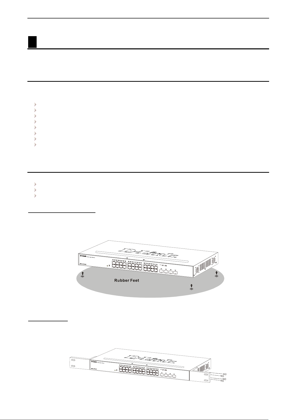
Desktop or Shelf Installation
The DGS-1210/ME series switches com e with a strip of four adhesive r ubber pa ds that c an be place d on th e
bottom of the device to pr event the de vice from dam aging the desk top or shelf it is places on. T o attach the
rubber pads, simpl y remove them from the adhes ive strip and stick one pa d on each corner on the b ottom
panel of the Switch.
Figure 2.1 – Attach the adhesive rubber pads to the bottom
Rack Installation
The switch can be mounted in an EIA standard size 19-inch r ack, which can be plac ed i n a wirin g closet with
other equipment. T o install, attac h the m ounting br ackets to th e switc h’s side p anels (one on each s ide) and
secure them with the screws provided (please note that these brackets are not designed for palm size
switches).
Figure 2.2 – Attach the mounting brackets to the Switch
1133

2 Hardware Installation DGS-1210 series Metro Ethernet Managed Switch User Manual
Then, use the screws provided with the equipment rack to mount the switch in the rack.
Figure 2.3 – Mount the Switch in the rack or chassis
Please be aware of following safety Instructions when installing:
A) Elevated Operat ing Ambient - If instal led in a closed or multi-unit rack assembly, the op erating ambient
temperature of the rac k environm ent ma y be greater than room ambient. T herefor e, considera tion should b e
given to installing the equ ip ment in an environment compatible with the maximum ambient temperature (Tma)
specified by the manufacturer.
B) Reduced Air Flow - Installation of the equipment in a rack should be such that the amount of air flow
required for safe operation of the equipment is not compromised.
C) Mechanical Loading - Mounting of the equipm ent in the r ack s hould be such th at a hazar dous c onditio n is
not achieved due to uneven mechanical loading.
D) Circuit Overloading - Consideration should be given to the connection of the equipment to the supply
circuit, and the eff ect that overl oading of the circu its m ight have on overc urrent pr otection a nd suppl y wiring.
Appropriate consideration of equipment nameplate ratings should be used when addressing this concern.
E) Reliable Earthing - Reliable earthing of rack-mounted equipment should be maintained. Particular
attention should be give n to supply connecti ons other than direct c onnections to the branch c ircuit (e.g. use
of power strips)."
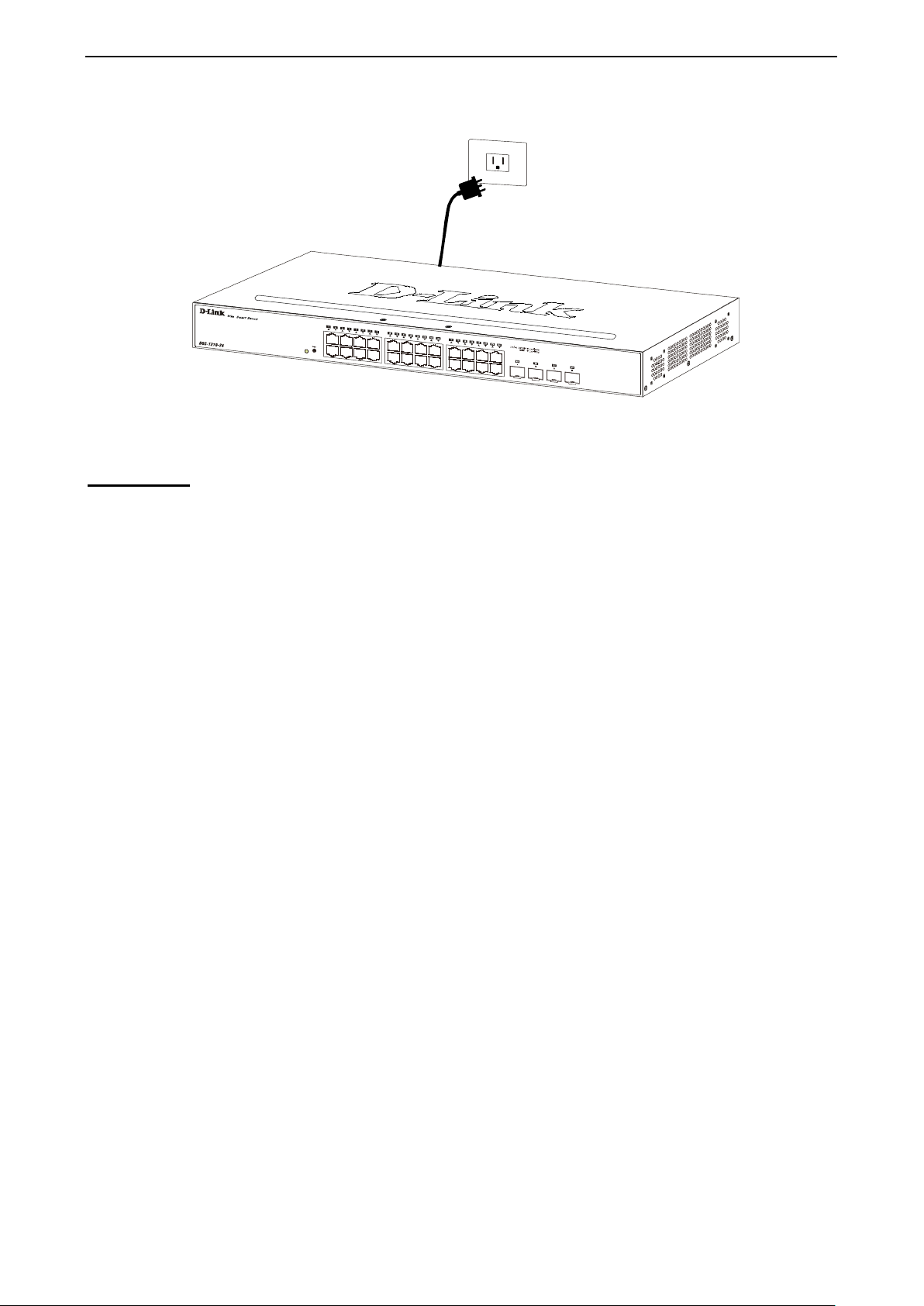
Step 3 – Plugging in the AC Power Cord
Users may now connect th e AC power cord into the r ear of the switch and to an electrical outlet (pref erably
one that is grounded and surge protected).
14
2 Hardware Installation DGS-1210 series Metro Ethernet Managed Switch User Manual
Figure 2.4 – Plugging the switch into an outlet
Power Failure
As a precaution, th e switch s hould be u nplugged in cas e of power f ailure. W hen po wer is resum ed, plug t he
switch back in.
1155

3 Getting Started DGS-1210 series Metro Ethernet Managed Switch User Manual
3 Getting Started
This chapter introduces the management interface of D-Link DGS-1210/ME Metro Ethernet Switch.
Management Options
Using Web-based Managemen t
Connecting to the Console Port
Management Options
The D-Link DGS-1210/ME Metro Ethernet Switch can be managed thro ugh any port on the device by using
the web-based management interface, or the D-Link Network Assistant (DNA).
Each switch must be assigned its own IP address, which is used for comm unication with the web-based
management interface or a SNMP network manager. T he PC should have an I P address in the sam e range
as the Switch. Each Switch allows up to four users to access the web-based management interface
concurrently.
However, if you want to manage multiple D-Link Smart Managed Switches, the D-Link Network Assistant
(DNA) is a more convenient choice. By using the D-Link Network Assistant (DNA), you do not need to
change the IP address of your PC, making it easier to simultaneously initialize multiple D-Link Managed
Switches.
Please refer to the fol lowing installat ion instructions f or the Web interface and the D-Link Network Assistant
(DNA).
Using Web-based Management Interface
After successfully installing the Switch, you can configure the Switch, monitor the network st atus, and disp lay
statistics using a web browser.
Supported Web Browsers
The embedded Web-based Management currently supports the following web browsers:
Microsoft Internet Explorer 10/11
Microsoft Edge 25
Chrome 51
Safari 5.1.7
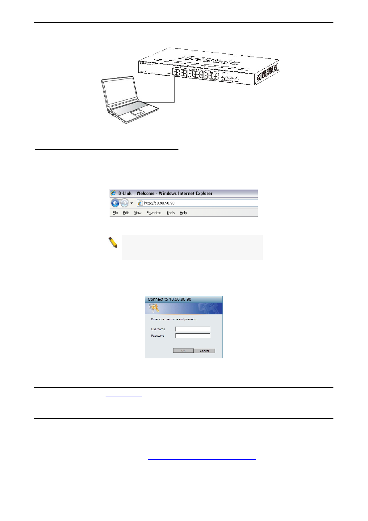
Connecting to the Switch
The access the web interface you will need the following equipment:
1. A PC with a RJ45 Ethernet port.
2. A standard Ethernet cable
Connect on end of the Ethernet cabl e to any of the p orts on the front pa nel of the Sw itch and connect the
other end of Ethernet cable to the Ethernet port on the PC.
16
3 Getting Started DGS-1210 series Metro Ethernet Managed Switch User Manual
Figure 3.1 – Connected Ethernet cable
Accessing the Web-based Management Interface
In order to access t he management interf ace, the PC m ust have an IP address i n the same subnet as the
switch. For exam ple, if the switch has an IP address of 10.90.90.90, the PC should have an IP address of
10.x.y.z (where x/y is a number between 0 ~ 254 and z is a number between 1 ~ 254), and a subn et mask of
255.0.0.0. T o launch the w eb interf ace, simply open any compatible web browser and enter 10.90.90.90 (the
factory-default IP address) in the address bar. Then press <Enter>.
Figure 3.2 –Enter the IP address 10.90.9 0.90 in the web browser
NOTE: T he switch's f actor y default IP addres s is
10.90.90.90 with a subne t m ask of 255.0.0 .0 and
a default gateway of 0.0.0.0.
When the following logon dialog box appears, enter the password and choose the language of the W ebbased Management interface then click OK.
By default, the Username and Password are empty.
Figure 3.3 – Logon Dia log Box
Web-based Management
Please refer to Chapter 4 Configuration for detailed instructions.
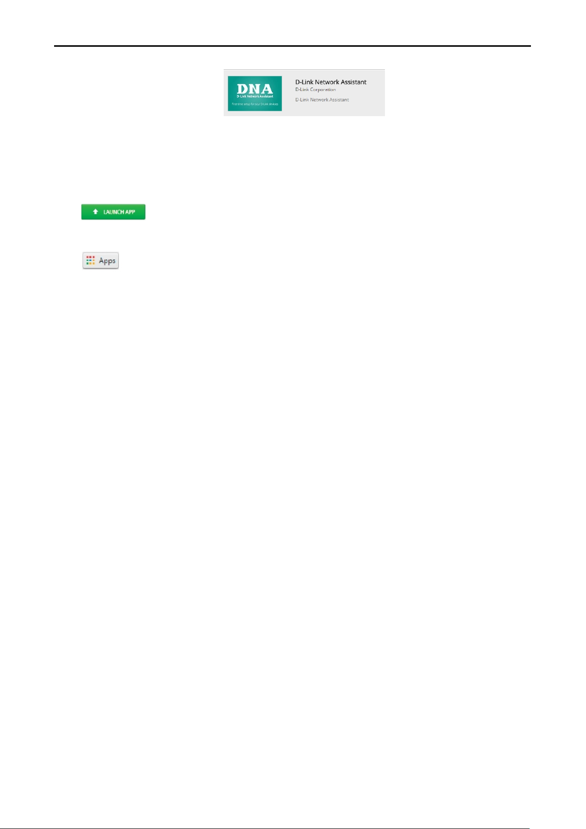
D-Link Network Assistant (DNA)
D-Link Network Assistant ( DNA) is a program that is used t o disco ver switc hes which are in the sam e La yer
2 network segment as your PC. You can do wnload the DNA App fr om the Chrome web s tore and instal l it in
a Chrome web browser.
1. Go to the Chrome web store at: https://chrome.google.com/webstore
Network Assistant.
1177
, and search the store for
3 Getting Started D-Link DGS-1210-52/ME-28/ME User
Manual
Figure 3.4 – D-LINK Network Assistant
2. Click ‘ADD TO CHROME’ button on the right hand side of the search results.
3. Click ‘Add app’ button in the pop-up window to install the D-Link Network Assistant in Chrome.
4. When the installation process has finished:
(Option 1) Click the ‘LAUNCH APP’ button in the upper-right corner of the window to start DNA.
(Option 2) Click the ‘Apps ’ icon in the upper-lef t corner of the Chrom e browser and click the DNA icon
to start the app.
18
4 Configuration DGS-1210 series Metro Ethernet Managed Switch User Manual
If you close the web browser without
4 Configuration
The features and func tions of the D-Link DGS-1210/ME Metro Ethernet Switch can be configured throug h
the web-based management interface.
Web-based Management
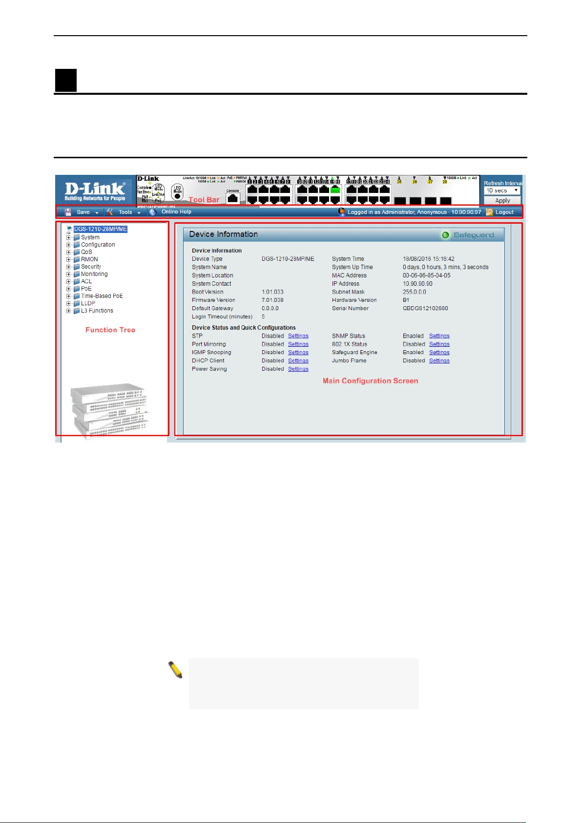
After press the OK butt on i n Logon Dialog Box, you will see the screen below:
Figure 4.1 – Web-based Management
The three main areas are the Tool Bar on top, the F unction Tree o n the left, a nd the Main Configuration
Screen.
The Tool Bar provides a quick and convenient way for accessing essential functions such as firmware
upgrades and basic settings.
Clicking on a section or s ubsection in the f unction tree wil l display all the sett ings of that section in the m ain
configuration scree n. The main configurati on screen will show the cur rent status of your Switch by clicking
the model name on top of the function tree.
In the upper-right corner of the screen the username and current IP address will be displayed.
Under the username is the Logout button. Click this to end this session.
NOTE:
clicking th e Logout button first, then it wil l b e seen
as an abnormal ex it and the log in session will s till
be occupied.
Finally, b y clic k ing on the D-Link logo at the upper-left corner of the screen you will be redirected to th e local
D-Link website.
19
4 Configuration DGS-1210 series Metro Ethernet Managed Switch User Manual
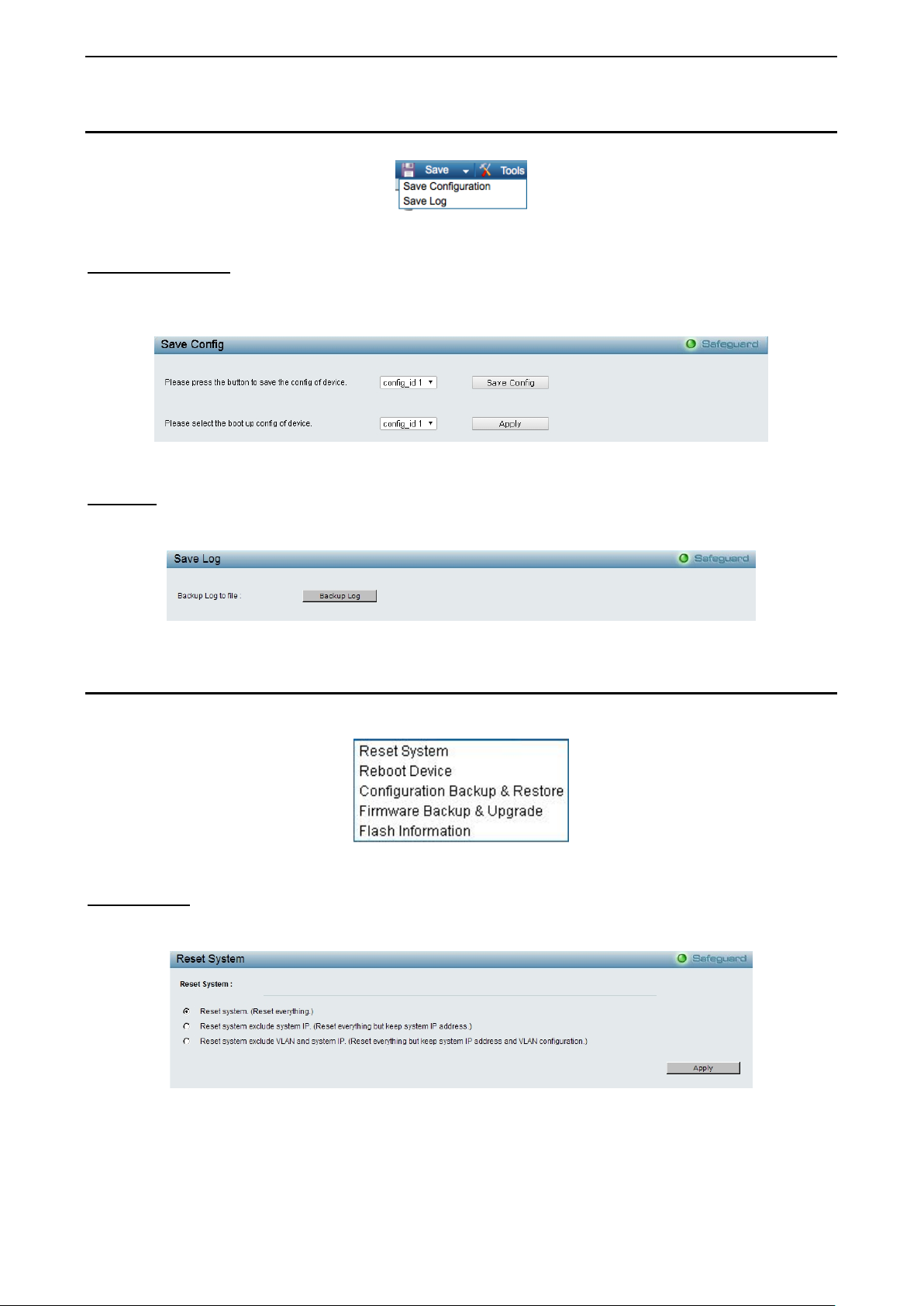
Tool Bar > Save Menu
The Save Menu provides Save Configuration and Save Log functions.
Figure 4.2 – Save Menu
Save Configuration
Select to save the e ntire configuration cha nges you have made of the device to switch’s no n-volatile RAM
then click Save Config button to take eff ect. Or select to boo t up the device f rom which config uration of the
device then click the Apply button to take effect.
Figure 4.3 – Save Configuration
Save Log
Save the log entries to your local drive and a pop-up mess age will prom pt you for the file path. You can view
or edit the log file by using text editor (e.g. Notepad).
Figure 4.4 – Save L og
Tool Bar > Tool Menu
The Tool Menu off ers global functi on controls suc h as Res et System, Reboot De vice, Conf iguration Back up
and Restore, Firmware Backup and Upgrade and Flash Information.
Figure 4.5 – Tool Menu
Reset System
Provide another safe res et option for the Switch. A ll configuration settings in non-volatile RAM will reset to
factory default and the Switch will reboot.
Figure 4.6 – Tool Menu > Reset System
Select the different reset method then click Apply to reset the system.
20
4 Configuration DGS-1210 series Metro Ethernet Managed Switch User Manual
Reboot Device Provide a safe way to reboot the system. Click Reboot to restart the switch.
Figure 4.7 – Tool Menu > Reboot Device
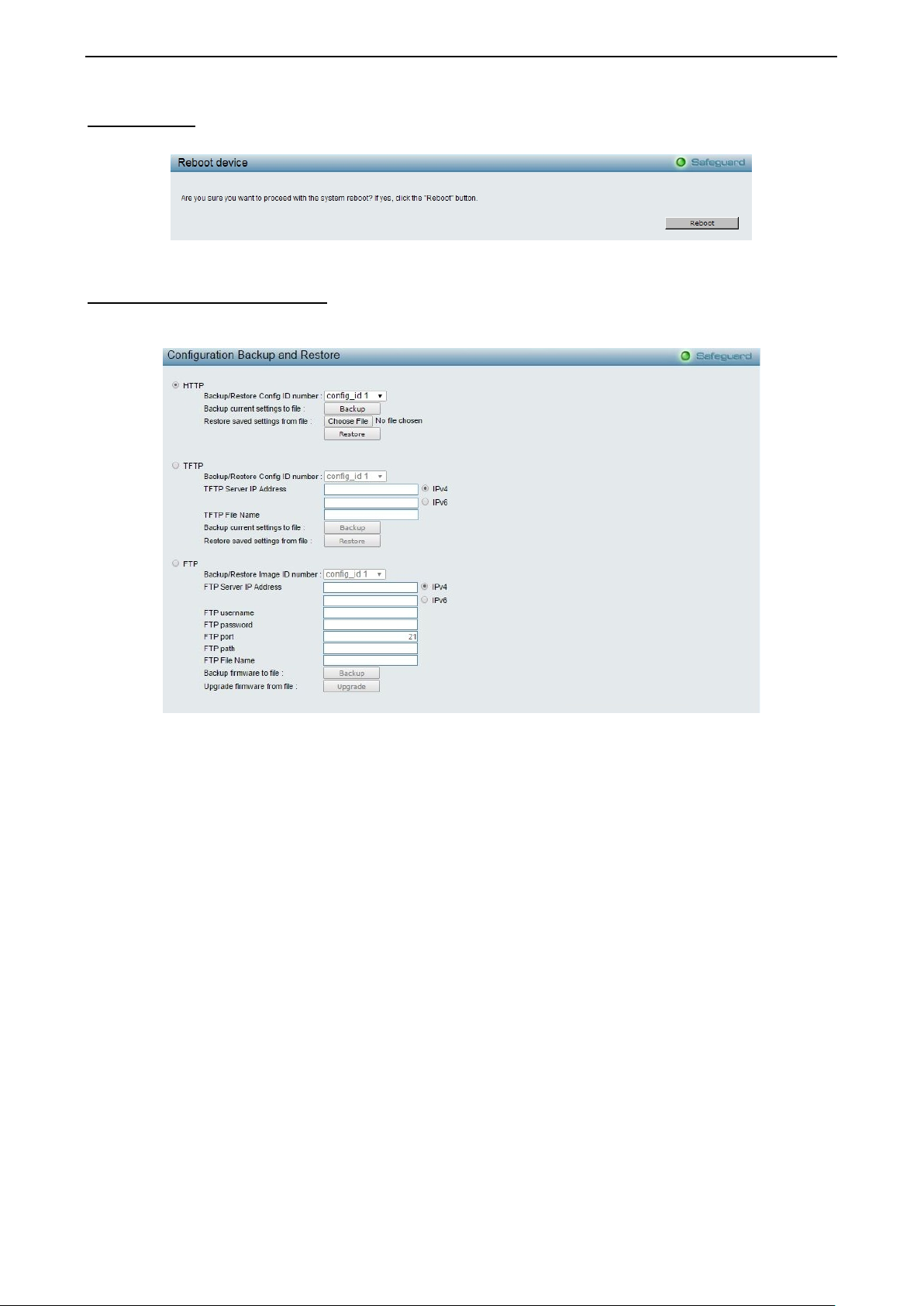
Configuration Backup & Restore
Allow the current c onfiguration sett ings to be save d to a file (not including the password), and if necessary,
you can restore configuration settings from this file. Three methods can be selected: HTTP, TFTP or FTP.
Figure 4.8 – Tool Menu > Configuration Backup and Restore
HTTP: Backup or restore the configuration file to or from your local drive.
Backup/Restore Config ID number: Specify the configuration ID number to be backup or restored.
Click Backup to save the current settings to your disk.
Click Choose File to browse your inventories for a saved backup settings file.
Click Restore after selecting the backup settings file you want to restore.
TFTP: TFTP (Trivial File Transfer Protocol) is a file transfer protocol that allows you to transfer files to a
remote TFTP server. The maximum Telnet Server co nnect ion is 4.
Backup/Restore Config ID number: Specify the configuration ID number to be backup or restored.
TFTP Server IP Address: Specif y the IPv4 or IPv6 addr ess .
TFTP File Name: Enter the file name which you want to save/restore from for the configuration.
Click Backup to save the current settings to the TFTP server.
Click Restore after selecting the backup settings file you want to restore.
FTP: FTP (File T ransfer Protocol) is a file transfer pro tocol that allows you to transfer file to a remote FTP
server.
Backup/Restore Image ID number: Specify to image ID number to be updated on the Switch.
FTP Server IP Address: Specify the IPv4 or IPv6 address.
FTP username: Enter the user name for the FTP server.
FTP password: Enter the user password for the FTP server.
FTP port: Enter the FTP port number. The default is 21.
2211
4 Configuration DGS-1210 series Metro Ethernet Managed Switch User Manual
FTP path: Specify the FTP path where the configuration file locat ed.
FTP File Name: Enter the file name which to be updated on the FTP server.
Click Backup to save the current settings to the FTP server.
Click Restore after selecting the backup settings file you want to restore.
Note: Switch will reboot after restore, and
all current configurations wi ll be lost.
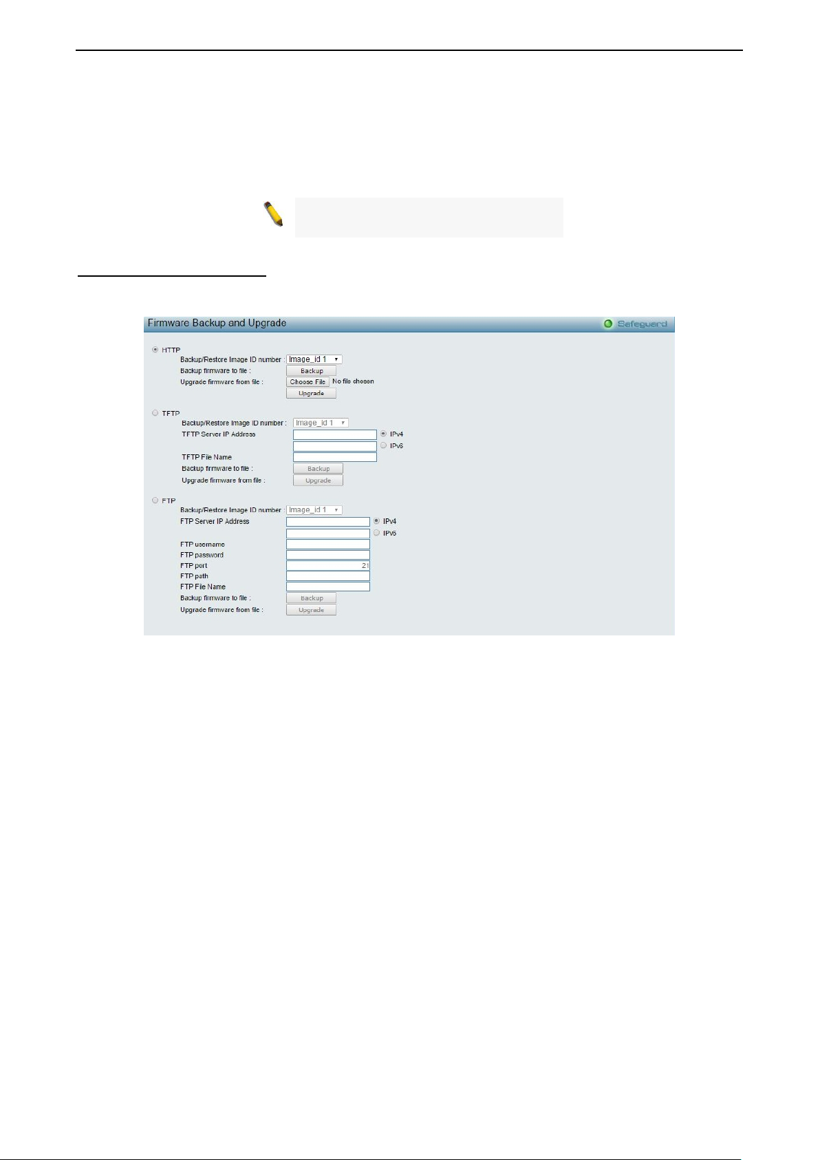
Firmware Backup & Upgrade
Allow for the firmware to be saved, or for an existing firmware file to be uploaded to the Switch. Two methods
can be selected: HTTP or TFTP.
Figure 4.9 – Tool Menu > Firmware Backup and Upgrade
HTTP: Backup or upgrade the firmware to or from your local PC drive.
Backup/Restore Image ID number: Specify the firmware image ID number to be backup or restored.
Click Backup to save the firmware to your disk.
Click Choose File to browse your inventories for a saved firmware file.
Click Upgrade after selecting the firmware file you want to restore.
TFTP: Backup or upgrade the firmware to or from a remote TFTP server. The maximum Telnet Server
connection is 4.
Backup/Restore Image ID number: Specify the firmware image ID number to be backup or restored.
TFTP Server IP Address: Specify the IPv4 or IPv6 addres s .
TFTP File Name: Enter the file name which you want to save/restore from for the firmware.
Click Backup to save the firmware to the TFTP server.
Click Upgrade after selecting the firmware file you want to restore.
FTP: Backup or restore the firmware to or from a FTP server.
Backup/Restore Image ID number: Specify to image ID number to be updated on the Switch.
FTP Server IP Address: Specify the IPv4 or IPv6 address.
FTP username: Enter the user name for the FTP server.
FTP password: Enter the user password for the FTP server.
FTP port: Enter the FTP port number. The default is 21.
22
4 Configuration DGS-1210 series Metro Ethernet Managed Switch User Manual
FTP path: Specify the FTP path where the firmware file located.
FTP File Name: Enter the file name which to be updated on the FTP server.
Click Backup to save the current firmware to the FTP server.
Click Restore after selecting the backup firmware file you want to restore.
CAUTION: Do n ot disconnect the PC or remove
the power cord from device until the upgrade
completes. The Switch may crash if the
Firmware upgrade is incomplete.
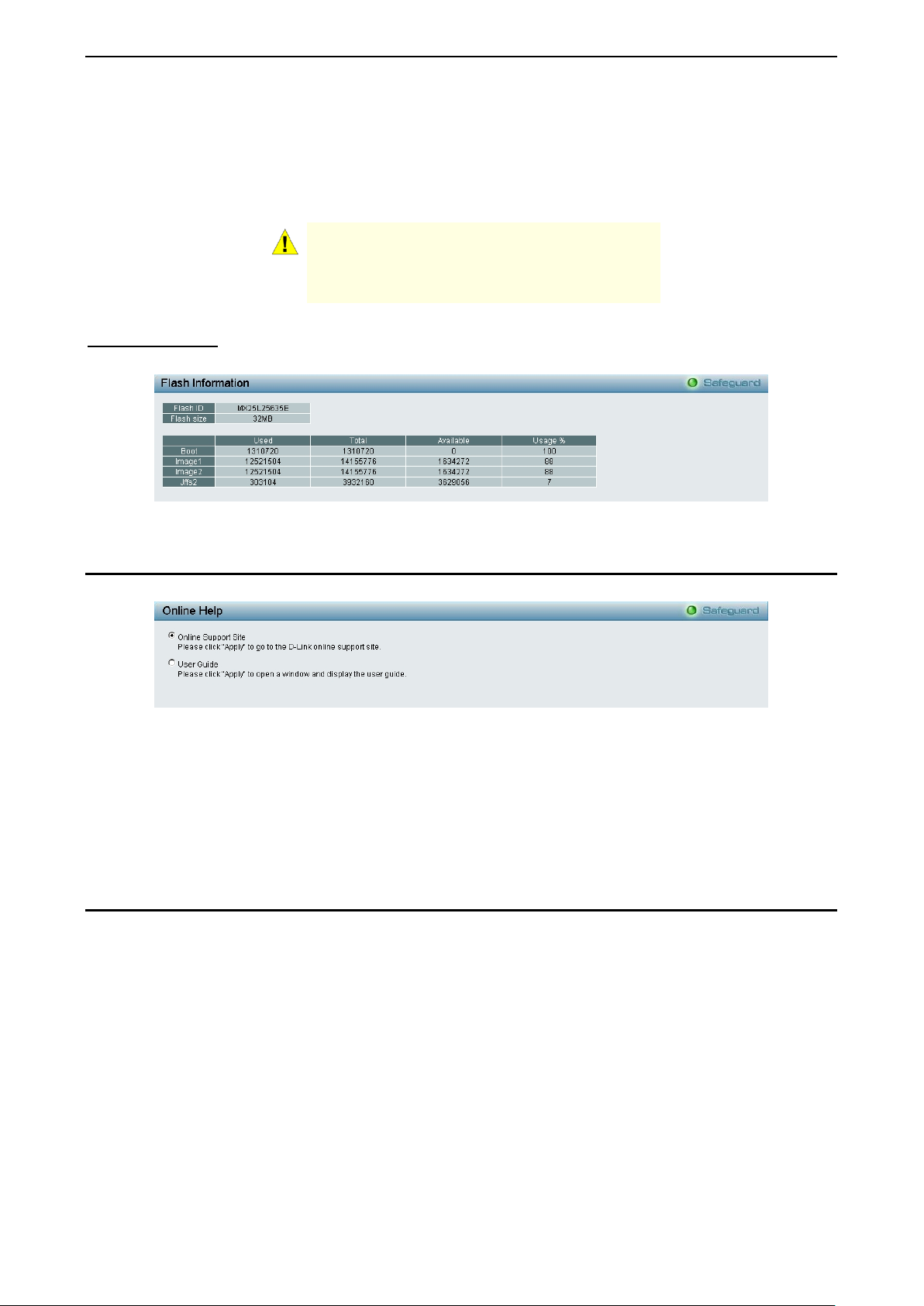
Flash Information
The Flash Information page displays the detail information of flash on the Switch.
Figure 4.10 – Tool Menu > Flash Information
Tool Bar > Online Help
The Online Help provides two ways of online support:
Figure 4.11 – Online Help
D-Link Support Site: This will lead you to the D-Lin k website where you can find on line reso urces suc h as
updated firmware images.
User Guide: This can offer an immediate reference for the feature definition or configuration guide.
Click Apply to make configuration take effect.
Function Tree
All configuration opt ions o n the switch are accessed thr ough t he function menu on the lef t s ide of the s c reen .
Click on the setup item that you want to configure. The following s ections provid e more detailed description
of each feature and function.
2233
 Loading...