

D-Link DES-3526DC, DES-3550, DES-3526 User Manual

©Copyright 2006. All Rights Reserved
User Manual
Product Model:
TM
DES-3500 Series
Layer 2 Managed Stackable Fast Ethernet Switch
Release 4

ii
__________________________________________________________________________________
Information in this document is subject to change without notice.
© 2006 D-Link Corporation. All rights reserved.
Reproduction in any manner whatsoever without the written permission of D-Link Corporation is strictly forbidden.
Trademarks used in this text: D-Link and the D-LINK logo are trademarks of D-Link Corporation; Microsoft and Windows are registered trademarks of Microsoft
Corporation.
Other trademarks and trade names may be used in this document to refer to either the entities claiming the marks and names or their products. D-Link Corporation
disclaims any proprietary interest in trademarks and trade names other than its own.
July 2006 P/N 651ES3526095G

Table of Contents
Preface ...............................................................................................................................................................................................vii
Intended Readers...............................................................................................................................................................................viii
Typographical Conventions........................................................................................................................................................viii
Notes, Notices, and Cautions............................................................................................................................................................viii
Safety Instructions ..............................................................................................................................................................................ix
Safety Cautions.............................................................................................................................................................................ix
General Precautions for Rack-Mountable Products.......................................................................................................................x
Protecting Against Electrostatic Discharge...................................................................................................................................xi
Introduction..........................................................................................................................................................................................1
Gigabit Ethernet Technology......................................................................................................................................................... 1
Switch Description......................................................................................................................................................................... 1
Features.......................................................................................................................................................................................... 2
Ports ............................................................................................................................................................................................... 2
Front-Panel Components................................................................................................................................................................ 2
LED Indicators............................................................................................................................................................................... 3
Rear Panel Description................................................................................................................................................................... 4
Side Panel Description................................................................................................................................................................... 4
Gigabit Combo Ports...................................................................................................................................................................... 5
Installation ...........................................................................................................................................................................................7
Package Contents........................................................................................................................................................................... 7
Before You Connect to the Network.............................................................................................................................................. 7
Installing the Switch without the Rack...........................................................................................................................................8
Installing the Switch in a Rack....................................................................................................................................................... 9
Mounting the Switch in a Standard 19" Rack..............................................................................................................................10
Power On (AC Power)..................................................................................................................................................................................11
Power Failure .................................................................................................................. ..............................................................................11
Connecting DC Power to DES-3526DC...................................................................................................................................... 11
Connecting the Switch....................................................................................................................................................................... 12
Switch to End Node ..................................................................................................................................................................... 12
Switch to Hub or Switch..............................................................................................................................................................13
Connecting To Network Backbone or Server .............................................................................................................................. 14
Introduction to Switch Management.................................................................................................................................................. 15
Management Options.........................................................................................................................................................................15
Web-based Management Interface............................................................................................................................................... 15
SNMP-Based Management.......................................................................................................................................................... 15
Connecting the Console Port (RS-232 DCE)............................................................................................................................... 15
First Time Connecting to the Switch............................................................................................................................................ 17
Password Protection..................................................................................................................................................................... 17

SNMP Settings............................................................................................................................................................................. 19
Traps.............................................................................................................................................................................................................19
MIBs.............................................................................................................................................................................................................19
IP Address Assignment................................................................................................................................................................ 20
Connecting Devices to the Switch ............................................................................................................................................... 21
Web-based Switch Configuration...................................................................................................................................................... 22
Introduction........................................................................................................................................................................................22
Login to Web Manager................................................................................................................................................................ 22
Web-based User Interface............................................................................................................................................................ 23
Areas of the User Interface ...........................................................................................................................................................................23
Web Pages.................................................................................................................................................................................... 24
Configuring the Switch...................................................................................................................................................................... 25
Switch Information............................................................................................................................................................................26
IP Address.......................................................................................................................................................................................... 26
Advanced Settings .............................................................................................................................................................................29
Port Configurations............................................................................................................................................................................ 31
Port Description................................................................................................................................................................................. 32
Port Mirroring....................................................................................................................................................................................33
Link Aggregation...............................................................................................................................................................................34
Understanding Port Trunk Groups................................................................................................................................................................34
LACP Port Setting.............................................................................................................................................................................37
MAC Notification.............................................................................................................................................................................. 38
MAC Notification Global Settings............................................................................................................................................... 38
MAC Notification Port Settings................................................................................................................................................... 39
IGMP .................................................................................................................................................................................................40
IGMP Snooping ........................................................................................................................................................................... 40
Static Router Ports Entry.............................................................................................................................................................. 42
Forbidden Router Ports Entry......................................................................................................................................................43
Spanning Tree....................................................................................................................................................................................44
802.1s MSTP ................................................................................................................................................................................................44
802.1w Rapid Spanning Tree ........................................................................................................................................................................44
Port Transition States....................................................................................................................................................................................44
Edge Port.......................................................................................................................................................................................................45
P2P Port........................................................................................................................................................................................................45
802.1d/802.1w/802.1s Compatibility............................................................................................................................................................45
STP Loopback Detection..............................................................................................................................................................................45
STP Bridge Global Settings.........................................................................................................................................................46
MST Configuration Table............................................................................................................................................................ 49
MSTI Settings..............................................................................................................................................................................51
STP Instance Settings................................................................................................................................................................... 52
MSTP Port Information................................................................................................................................................................53
Forwarding Filtering.......................................................................................................................................................................... 55

Unicast Forwarding...................................................................................................................................................................... 55
Multicast Forwarding................................................................................................................................................................... 55
Multicast Port Filtering Mode...................................................................................................................................................... 57
VLANs...............................................................................................................................................................................................58
Understanding IEEE 802.1p Priority.............................................................................................................................................................58
VLAN Description....................................................................................................................................................................... 58
Notes about VLANs on the xStack DES-3500 Series switches ....................................................................................................................58
IEEE 802.1Q VLANs................................................................................................................................................................... 58
802.1Q VLAN Tags......................................................................................................................................................................................60
Port VLAN ID...............................................................................................................................................................................................60
Tagging and Untagging.................................................................................................................................................................................61
Ingress Filtering............................................................................................................................................................................................61
Default VLANs.............................................................................................................................................................................................61
Port-based VLANs........................................................................................................................................................................................62
VLAN Segmentation.....................................................................................................................................................................................62
Asymmetric VLANs.....................................................................................................................................................................................63
VLAN and Trunk Groups .............................................................................................................................................................................64
Static VLAN Entry....................................................................................................................................................................... 64
GVRP Setting............................................................................................................................................................................... 66
Traffic Control ............................................................................................................................................................................. 67
Port Security................................................................................................................................................................................. 69
QoS....................................................................................................................................................................................................70
Advantages of QoS.......................................................................................................................................................................................70
Understanding QoS....................................................................................................................................................................................... 71
Port Bandwidth ............................................................................................................................................................................ 72
Scheduling.................................................................................................................................................................................... 73
802.1p Default Priority.................................................................................................................................................................74
802.1p User Priority..................................................................................................................................................................... 74
Traffic Segmentation.................................................................................................................................................................... 75
System Severity Alerts.......................................................................................................................................................................76
System Log Server............................................................................................................................................................................. 76
SNTP Settings.................................................................................................................................................................................... 78
Time Setting................................................................................................................................................................................. 78
Time Zone and DST..................................................................................................................................................................... 79
Access Profile Table..........................................................................................................................................................................81
Configuring the Access Profile Table..........................................................................................................................................81
CPU Interface Filtering...................................................................................................................................................................... 92
CPU Interface Filtering Profile Table..........................................................................................................................................92
Port Access Entity (802.1X)............................................................................................................................................................102
802.1x Port-Based and MAC-Based Access Control................................................................................................................. 102
Authentication Server .................................................................................................................................................................................103
Authenticator .............................................................................................................................................................................................. 103

Client...........................................................................................................................................................................................................104
Authentication Process............................................................................................................................................................... 104
Port-Based Network Access Control..........................................................................................................................................105
MAC-Based Network Access Control.......................................................................................................................................106
Configure Authenticator............................................................................................................................................................. 107
PAE System Control.................................................................................................................................................................. 109
Port Capability............................................................................................................................................................................................109
Initializing Ports for Port Based 802.1x......................................................................................................................................................110
Initializing Ports for MAC Based 802.1x....................................................................................................................................................111
Reauthenticate Port(s) for Port Based 802.1x.............................................................................................................................................111
RADIUS Server ......................................................................................................................................................................... 112
IP-MAC Binding..............................................................................................................................................................................113
ACL Mode ................................................................................................................................................................................. 113
IP-MAC Binding Port................................................................................................................................................................115
IP-MAC Binding Table.............................................................................................................................................................. 116
IP-MAC Binding Blocked.......................................................................................................................................................... 117
Limited IP Multicast Range Settings...............................................................................................................................................118
Layer 3 IP Networking.....................................................................................................................................................................119
Static ARP Table........................................................................................................................................................................ 119
DHCP/BOOTP Relay................................................................................................................................................................. 120
DHCP / BOOTP Relay Global Settings......................................................................................................................................................120
The Implementation of DHCP Information Option 82 in the xStack DES-3500 Series switches...............................................................122
DHCP/BOOTP Relay Interface Settings.....................................................................................................................................................123
Management.....................................................................................................................................................................................124
Security IP ....................................................................................................................................................................................... 124
User Accounts.................................................................................................................................................................................. 124
Admin and User Privileges.........................................................................................................................................................................125
Access Authentication Control........................................................................................................................................................126
Policy & Parameters................................................................................................................................................................... 127
Application's Authentication Settings........................................................................................................................................ 127
Authentication Server Group Settings........................................................................................................................................ 128
Authentication Server Hosts....................................................................................................................................................... 129
Login Method Lists.................................................................................................................................................................... 131
Enable Method Lists .................................................................................................................................................................. 132
Local Enable Password..............................................................................................................................................................133
Enable Admin ............................................................................................................................................................................ 134
Secure Socket Layer (SSL)..............................................................................................................................................................135
Download Certificate.................................................................................................................................................................135
Configuration.............................................................................................................................................................................136
Secure Shell (SSH) ..........................................................................................................................................................................137
SSH Configuration..................................................................................................................................................................... 137
SSH Algorithm........................................................................................................................................................................... 138

SSH User Authentication........................................................................................................................................................... 140
SNMP Manager ...............................................................................................................................................................................141
SNMP Settings........................................................................................................................................................................... 141
Traps...........................................................................................................................................................................................................141
MIBs...........................................................................................................................................................................................................141
SNMP User Table......................................................................................................................................................................142
SNMP View Table..................................................................................................................................................................... 144
SNMP Group Table.................................................................................................................................................................... 145
SNMP Community Table Configuration ................................................................................................................................... 146
SNMP Host Table......................................................................................................................................................................147
SNMP Engine ID....................................................................................................................................................................... 148
Safeguard Engine ............................................................................................................................................................................. 149
Monitoring.......................................................................................................................................................................................151
Port Utilization.................................................................................................................................................................................151
CPU Utilization................................................................................................................................................................................152
Packets.............................................................................................................................................................................................153
Received (RX)............................................................................................................................................................................ 153
UMB Cast (RX).........................................................................................................................................................................154
Transmitted (TX) ....................................................................................................................................................................... 156
Errors ...............................................................................................................................................................................................158
Received (RX)............................................................................................................................................................................ 158
Transmitted (TX) ....................................................................................................................................................................... 159
Size .................................................................................................................................................................................................. 161
MAC Address..................................................................................................................................................................................163
Switch History Log..........................................................................................................................................................................164
IGMP Snooping Group.................................................................................................................................................................... 165
IGMP Snooping Forwarding............................................................................................................................................................166
VLAN Status....................................................................................................................................................................................167
Router Port....................................................................................................................................................................................... 167
Port Access Control.........................................................................................................................................................................168
Authenticator State..................................................................................................................................................................... 168
Layer 3 Feature................................................................................................................................................................................ 170
Browse ARP Table..................................................................................................................................................................... 170
Safeguard Engine Status..................................................................................................................................................................171
Maintenance..................................................................................................................................................................................... 172
TFTP Services..................................................................................................................................................................................172
Download Firmware from TFTP Server.................................................................................................................................... 172
Download Configuration File..................................................................................................................................................... 173
Upload Configuration................................................................................................................................................................. 173
Upload Log ................................................................................................................................................................................ 174
Multiple Image Services..................................................................................................................................................................175

Firmware Information................................................................................................................................................................ 175
Config Firmware Image............................................................................................................................................................. 176
Ping Test..........................................................................................................................................................................................176
Save Changes................................................................................................................................................................................... 177
Reset ................................................................................................................................................................................................ 177
Reset System.................................................................................................................................................................................... 178
Reset Config .................................................................................................................................................................................... 178
Reboot Device..................................................................................................................................................................................178
Logout.............................................................................................................................................................................................. 178
D-Link Single IP Management........................................................................................................................................................ 179
Single IP Management (SIM) Overview..........................................................................................................................................179
The Upgrade to v1.6....................................................................................................................................................................................180
SIM Using the Web Interface ..........................................................................................................................................................181
Topology.......................................................................................................................................................................................... 182
Tool Tips.......................................................................................................................................................................................... 184
Right-Click................................................................................................................................................................................. 185
Group Icon..................................................................................................................... .............................................................................185
Commander Switch Icon.............................................................................................................................................................................186
Member Switch Icon...................................................................................................................................................................................187
Candidate Switch Icon................................................................................................................................................................................187
Menu Bar ................................................................................................................................................................................... 189
Group..........................................................................................................................................................................................................189
Device.........................................................................................................................................................................................................189
View............................................................................................................................................................................................................189
Firmware Upgrade........................................................................................................................................................................... 190
Configuration File Backup/Restore............................................................................................................................................ 190
Upload Log File......................................................................................................................................................................... 190
Technical Specifications.................................................................................................................................................................. 191
Cables and Connectors.....................................................................................................................................................................193
System Log Entries..........................................................................................................................................................................194
Cable Lengths..................................................................................................................................................................................205
Glossary........................................................................................................................................................................................... 206
Warrenties/Registration ...................................................................................................................................................................209
Tech Support.................................................................................................................................................................................... 217

xStack DES-3500 Series Layer 2 Stackable Fast Ethernet Managed Switch User Manual
vii
Preface
The DES-3500 Series Manual is divided into sections that describe the system installation and operating instructions with
examples.
Section 1, Introduction - Describes the Switch and its features.
Section 2, Installation- Helps you get started with the basic installation of the Switch and also describes the front panel, rear
panel, side panels, and LED indicators of the Switch. Included in this section is a description of how to hook up the DC power
supply for the DES-3500 Series switches.
Section 3, Connecting the Switch - Tells how you can connect the Switch to your Ethernet/Fast Ethernet network.
Section 4, Introduction to Switch Management - Introduces basic Switch management features, including password
protection, SNMP settings, IP address assignment and connecting devices to the Switch.
Section 5, Introduction to Web-based Switch Management - Talks about connecting to and using the Web-based switch
management feature on the Switch.
Section 6, Configuring the Switch - A detailed discussion about configuring some of the basic functions of the Switch,
including accessing the Switch information, using the Switch's utilities and setting up network configurations, such as Quality
of Service, The Access Profile Table, port mirroring and configuring the Spanning Tree.
Section 7, Management - A discussion of the security features of the Switch, including Security IP, User Accounts, Access
Authentication Control, and SNMP.
Section 8, Monitoring - Features graphs and screens used in monitoring features an d pa ckets on the Switch.
Section 9, Maintenance - Features information on Switch utility functions, including TFTP Services, Switch History, Ping Test
Save Changes and Rebooting Services.
Section 10, Single IP Management - Discussion on the Single IP Management function of the Switch, including functions and
features of the Java based user interface and the utilities of the SIM function.
Appendix A, Technical Specifications - The technical specifications of the DES-3500 Series switches.
Appendix B, Cables and Connectors - Describes the RJ-45 receptacle/connector, straight through and crossover cables and
standard pin assignments.
Appendix C, Cable Lengths - Information on cable types and maximum distances.
Glossary - Lists definitions for terms and acronyms used in this document.

xStack DES-3500 Series Layer 2 Stackable Fast Ethernet Managed Switch User Manual
viii
Intended Readers
The DES-3500 Manual contains information for setup and management of the Switch. This manual is intended for network
managers familiar with network management concepts and terminology.
Typographical Conventions
Convention Description
[ ]
In a command line, square brackets indicate an optional entry. For example: [copy
filename] means that optionally you can type copy followed by the name of the file. Do not
type the brackets.
Bold font
Indicates a button, a toolbar icon, menu, or menu item. For example: Open the File menu
and choose Cancel. Used for emphasis. May also indicate system messages or prompts
appearing on your screen. For example: You have mail. Bold font is also used to
represent filenames, program names and commands. For example: use the copy
command.
Boldface
Typewriter Font
Indicates commands and responses to prompts that must be typed exactly as printed in
the manual.
Initial capital letter
Indicates a window name. Names of keys on the keyboard have initial capitals. For
example: Click Enter.
Italics
Indicates a window name or a field. Also can indicate a variables or parameter that is
replaced with an appropriate word or string. For example: type filename means that you
should type the actual filename instead of the word shown in italic.
Menu Name > Menu
Option
Menu Name > Menu Option Indicates the menu structure. Device > Port > Port
Properties means the Port Properties menu option under the Port menu option that is
located under the Device menu.
Notes, Notices, and Cautions
A NOTE indicates important information that helps you make better use of your device.
A NOTICE indicates either potential damage to hardware or loss of data and tells you
how to avoid the problem.
A CAUTION indicates a potential for property damage, personal injury, or death.

xStack DES-3500 Series Layer 2 Stackable Fast Ethernet Managed Switch User Manual
ix
Safety Instructions
Use the following safety guidelines to ensure your own personal safety and to help protect your system from potential damage.
Throughout this document, the caution icon ( ) is used to indicate cautions and precautions that you need to review and follow.
Safety Cautions
To reduce the risk of bodily injury, electrical shock, fire, and damage to the equipment, observe the following precautions.
• Observe and follow service markings.
• Do not service any product except as explained in your system documentation.
• Opening or removing covers that are marked with the triangular symbol with a lightning bolt may expose you to
electrical shock.
• Only a trained service technician should service components inside these compartments.
• If any of the following conditions occur, unplug the product from the electrical outlet and replace the part or contact your
trained service provider:
• The power cable, extension cable, or plug is damaged.
• An object has fallen into the product.
• The product has been exposed to water.
• The product has been dropped or damaged.
• The product does not operate correctly when you follow the operating instructions.
• Keep your system away from radiators and heat sources. Also, do not block cooling vents.
• Do not spill food or liquids on your system components, and never operate the product in a wet environment. If the system
gets wet, see the appropriate section in your troubleshooting guide or contact your trained service provider.
• Do not push any objects into the openings of your system. Doing so can cause fire or electric shock by shorting ou t interior
components.
• Use the product only with approved equipment.
• Allow the product to cool before removing covers or touching internal components.
• Operate the product only from the type of external power source indicated on the electrical ratings label. If you are not sure
of the type of power source required, consult your service provider or local power company.
• To help avoid damaging your system, be sure the voltage on the power supply is set to match the power available at your
location:
• 115 volts (V)/60 hertz (Hz) in most of North and South America and some Far Eastern countries such as South Korea
and Taiwan
• 100 V/50 Hz in eastern Japan and 100 V/60 Hz in western Japan
• 230 V/50 Hz in most of Europe, the Middle East, and the Far East
• –48 VDC for DC power supply unit on DES-3526DC only
• Also, be sure that attached devices are electrically rated to operate with the power available in your location.
• Use only approved power cable(s). If you have not been provided with a power cable for your system or for any AC-
powered option intended for your system, purchase a power cable that is ap proved for use in your country. The power cable
must be rated for the product and for the voltage and current marked on the product's electrical ratings label. The voltage and
current rating of the cable should be greater than the ratings marked on the product.
• To help prevent electric shock, plug the system and peripheral power cables into properly grounded electrical outlets. These
cables are equipped with three-prong plugs to help ensure proper grounding. Do not use adapter plugs or remove the
grounding prong from a cable. If you must use an extension cable, use a 3-wire cable with properly grounded plugs.

xStack DES-3500 Series Layer 2 Stackable Fast Ethernet Managed Switch User Manual
x
• Observe extension cable and power strip ratings. Make sur e that the total ampere rating of all products plugged into the
extension cable or power strip does not exceed 80 percent of the ampere ratings limit for the extension cable or power strip.
• To help protect your system from sudden, transient increases and decreases in electrical power, use a surge suppressor, line
conditioner, or uninterruptible power supply (UPS).
• Position system cables and power cables carefully; route cables so that they cannot be stepped on or tripped over. Be sure
that nothing rests on any cables.
• Do not modify power cables or plugs. Consult a licensed electrician or your power company for site modifications. Always
follow your local/national wiring rules.
• When connecting or disconnecting power to hot-pluggable power supplies, if offered with your system, observe the
following guidelines:
• Install the power supply before connecting the power cable to the power supply.
• Unplug the power cable before removing the power supply.
• If the system has multiple sources of power, disconnect power from the system by unplugging all power cables from
the power supplies.
• Move products with care; ensure that all casters and/or stabilizers are firmly connected to the system. Avoid sudden stops
and uneven surfaces.
General Precautions for Rack-Mountable Products
Observe the following precautions for rack stability an d safety. Also, refer to the rack installation documentation accompanying
the system and the rack for specific caution statements and procedures.
• Systems are considered to be components in a rack. Thus, "component" refers to any system as well as to various peripherals
or supporting hardware.
• Before working on the rack, make sure that the stabilizers are secured to the rack, extended to the floor, and that the full
weight of the rack rests on the floor. Install front and side stabilizers on a single rack or front stabilizers for joined multiple
racks before working on the rack.
• Always load the rack from the bottom up, and load the heaviest item in the rack first.
• Make sure that the rack is level and stable before extending a component from the rack.
• Use caution when pressing the component rail release latches and sliding a component into or out of a rack; the slide rails
can pinch your fingers.
• After a component is inserted into the rack, carefully extend the rail into a locking position, and then slide the component
into the rack.
• Do not overload the AC supply branch circuit that provides power to the rack. The total rack load should not exceed 80
percent of the branch circuit rating.
• Ensure that proper airflow is provided to components in the rack.
• Do not step on or stand on any component when servicing other components in a rack.
NOTE: A qualified electrician must perform all connections to DC power and to safety grounds.
All electrical wiring must comply with applicable local, regional or national codes and practices.
CAUTION: Never defeat the ground conductor or operate the equipment in the absence of a
suitably installed ground conductor. Contact the appropriate electrical inspection authority or an
electrician if you are uncertain that suitable grounding is available.
CAUTION: The system chassis must be positively grounded to the rack cabinet frame. Do not
attempt to connect power to the system until grounding cables are connected. A qualified
electrical inspector must inspect completed power and safety ground wiring. An energy hazard
will exist if the safety ground cable is omitted or disconnected.

xStack DES-3500 Series Layer 2 Stackable Fast Ethernet Managed Switch User Manual
xi
Protecting Against Electrostatic Discharge
Static electricity can harm delicate components inside your system. To prevent static damage, discharge static electricity from
your body before you touch any of the electronic components, such as the microprocessor. You can do so by periodically touching
an unpainted metal surface on the chassis.
You can also take the following steps to prevent damage from electrostatic discharge (ESD):
1. When unpacking a static-sensitive component from its shipping carton, do not remove the component from the antistatic
packing material until you are ready to install the component in your system. Just before unwrapping the antistatic
packaging, be sure to discharge static electricity from your body.
2. When transporting a sensitive component, first place it in an antistatic container or packaging.
3. Handle all sensitive components in a static-safe area. If possible, use antistatic floor pads, workbench pads and an
antistatic grounding strap.

xStack DES-3500 Series Layer 2 Stackable Fast Ethernet Managed Switch User Manual
1
Section 1
Introduction
Gigabit Ethernet Technology
Switch Description
Features
Ports
Front-Panel Components
Side Panel Description
Rear Panel Description
Gigabit Combo Ports
The DES-3500 layer 2 Gigabit Ethernet switches are members of the D-Link xStack family. Ranging from 10/100Mbps edge
switches to core gigabit switches, the xStack switch family has been future-proof designed to provide a stacking architecture with
fault tolerance, flexibility, port density, robust security and maximum throughput with a user-friendly management interface fo r
the networking professional.
The following manual describes the installation, maintenance and configurations concerning members of the xStack DES-3500
switch series. These three switches, the DES-3526, DES-3526DC, and the DES-3550 are all very similar in configur ations and
basic hardware and consequentially, most of the information in this manual will be universal to the whole xStack DES-3500
switch series. Corresponding screen pictures of the web manager may be taken from any one of these switches but the
configuration will be identical, except for varying port counts.
Please take note that if this device was purchased outside of Europe, certain cosmetic differences between the actual switch and
images in this document will be apparent to the reader, such as the faceplate and the manual cover. The DES-3500 Series has
already joined the xStack family for the European market and is soon to be xStack converted, universally. Changes are made to
the appearance of the device only and no configuration or internal hardware alterations occur.
Gigabit Ethernet Technology
Gigabit Ethernet is an extension of IEEE 802.3 Ethernet utilizing the same packet structure, format, and support for CSMA/CD
protocol, full duplex, flow control, and management objects, but with a tenfold increase in theoretical throughput over 100Mbps
Fast Ethernet and a one hundred-fold increase over 10Mbps Ethernet. Since it is compatible with all 10Mbps and 100Mbps Ethernet environments, Gigabit Ethernet provides a straightforward upgrade without wasting a company's existing investment in
hardware, software, and trained personnel.
The increased speed and extra bandwidth offered by Gigabit Ethernet are essential to coping with the network bottlenecks that
frequently develop as computers and their busses get faster and more users using applications that generate more traffic.
Upgrading key components, such as your backbone and servers to Gigabit Ethernet can greatly improve ne twork response times
as well as significantly speed up the traffic between your sub networks.
Gigabit Ethernet enables fast optical fiber connections to support video conferencing, complex imaging, and similar data-intensive
applications. Likewise, since data transfers occur 10 times faster than Fast Ethernet, servers outfitted with Gigabit Ethe rnet NIC's
are able to perform 10 times the number of operations in the same amount of time.
In addition, the phenomenal bandwidth delivered by Gigabit Ethernet is the most cost-effective method to take advantage of today
and tomorrow's rapidly improving switching and routing internetworking technologies.
Switch Description
The DES-3500 Series switches are equipped with unshielded twisted-pair (UTP) cable ports providing dedicated 10 or 100 Mbps
bandwidth. The Switch has 24 UTP ports (48 UTP ports for the DES-3550) and Auto MDI-X /MDI-II co nver tible po r ts that can be
used for unlinking to another switch. These ports can be used for connecting PCs, printers, servers, hubs, routers, switches and
other networking devices. The dual speed ports use standard twisted-pair cabling and are ideal for segmenting networks into small,
connected sub networks for superior performance. Each 10/100 port can support up to 200 Mbps of throughp ut in full-duplex
mode.
In addition, the Switch has 2 Mini-GBIC combo ports. These two-gigabit combo ports are ideal for connecting to a server or
network backbone.

xStack DES-3500 Series Layer 2 Stackable Fast Ethernet Managed Switch User Manual
2
This stand-alone Switch enables the network to use some of the most demanding multimedia and imaging applications
concurrently with other user applications without creating bottlenecks. The built-in con sole interface can be used to configure the
Switch's settings for priority queuin g, VLANs, and port trunk groups, port monitori n g, and port speed.
NOTE: For the remainder of this manual, all hardware versions of the DES-3500 Series
switches will be referred to as simply the Switch or the DES-3500 except where the differences
are relevant.
Features
• IEEE 802.3 10BASE-T compliant
• IEEE 802.3u 100BASE-TX compliant
• IEEE 802.1p Priority Queues
• IEEE 802.3x flow control in full duplex mode
• IEEE 802.3ad Link Aggregation Control Protocol
support.
• IEEE 802.1x Port-based and MAC-based Access
Control
• IEEE 802.1Q VLAN
• IEEE 802.1D Spanning Tree, IEEE 802.1W
Rapid Spanning Tree and IEEE 802.1s Multiple
Spanning Tree support
• Access Control List (ACL) support
• Single IP Management support
• Access Authentication Control utilizing
TACACS, XTACACS and TACACS+
• Dual Image Firmware
• Simple Network Time Protocol support
• MAC Notification support
• Asymmetric VLAN support
• System and Port Utilization support
• System Log Support
• Support port-based enable and disable
• Address table: Supports up to 8K MAC addresses
per device
• Supports a packet buffer of up to 3 Mbits
• Supports Port-based VLAN Groups
• Port Trunking with flexible load distribution and
fail-over function
• IGMP Snooping support
• SNMP support
• Secure Sockets Layer (SSL) and Secure Shell
(SSH) support
• Port Mirroring support
• MIB support for:
• RFC1213 MIB II
• RFC1493 Bridge
• RFC1757 RMON
• RFC1643 Ether-like MIB
• RFC2233 Interface MIB
• Private MIB
• RFC2674 for 802.1p
• IEEE 802.1x MIB
• RS-232 DCE console port for Switch
management
• Provides parallel LED display for port status such
as link/act, speed, etc.
• High performance switching engine performs forwarding and filtering at full wire speed, maximum 14, 881 packets/sec
on each 10Mbps Ethernet port, and maximum 148,810 packet/sec on 100Mbps Fast Ethernet port.
• Full- and half-duplex for both 10Mbps and 100Mbps connections. Full duplex allows the switch port to simultaneously
transmit and receive data. It only works with connections to full-duplex-capable end stations and switches. Connections
to a hub must take place at half-duplex
• Support broadcast storm filtering
• Non-blocking store and forward switching scheme capability to support rate adaptation and protocol conversion
• Supports by-port Egress/Ingress rate control.
• Supports IP-MAC Port Binding.
• Efficient self-learning and address recognition mechanism enables forwarding rate at wire speed
• Supports STP Loopback Detection
• Safeguard Engine Support

xStack DES-3500 Series Layer 2 Stackable Fast Ethernet Managed Switch User Manual
2
Ports
• Twenty-four (48 for the DES-3550) high-performance (MDI -X/MDI-II) ports for connecting to end stations, servers,
hubs and other networking devices.
• All UTP ports can auto-negotiate between 10Mbps and 100Mbps, half-duplex and full duplex, and feature flow control.
• Two 1000BASE-T Mini-GBIC combo port s fo r c on necti n g t o anot he r s wi tc h, ser ver , or n et wo rk bac k bo ne.
• RS-232 DCE Diagnostic port (console port) for setting up and managing the Switch via a connection to a console
terminal or PC using a terminal emulation program.
NOTE: For customers interested in D-View, D-Link Corporation's proprietary SNMP
management software, go to the D-Link Website (www.dlink.com.cn) and download
the software and manual.
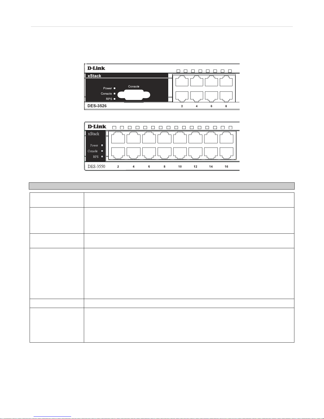
Front-Panel Components
The front panel of the Switch consists of LED indicators for power and for each 10/100 Mbps twisted-pair ports, and two
1000BASE-T Mini-GBIC ports.
Figure 1- 1. Front Panel View of the DES-3526 switch
Figure 1- 2. Front Panel View of the DES-3550 switch
The DES-3526DC does not support a redundant power supply and theref ore the RPS indicator does not appear on the front panel.
Figure 1- 3. Front Panel View of DES-3526DC
Comprehensive LED indicators display the status of the Switch and the network.
xStack DES-3500 Series Layer 2 Stackable Fast Ethernet Managed Switch User Manual
3
LED Indicators
The Switch supports LED indicators for Power, Console, RPS (DES-3500 Series switches only) and Port LEDs. The following
shows the LED indicators for the DES-3500 Series switches along with an explanation of each indicator. LEDs and there
corresponding meanings are displayed below.
Figure 1- 4. LED Indicators on DES-3526 Series switches
Figure 1- 5. Indicators on DES-3550 Series switch
LED Description
Power
This LED will light green after the Switch is powered on to indicate the ready state of the
device. The indicator is dark when the Switch is powered off.
Console
This LED should blink during the Power-On Self Test (POST). When the POST is finished,
the LED goes dark. This indicator is lit sold green when the Switch is being logged into via
out-of-band/local console management through the RS-232 console port in the back of the
Switch using a straight-through serial cable.
RPS (DES-3526DC
not supported)
This LED will be lit when the redundant power supply is present and in use. Otherwise it will
remain dark.
Port LEDs
One row of LEDs for each port is located above the ports on the front panel. The first LED is
for the top port and the second one is for the bottom ports. These port LEDs will light two
different colors for 10M and 100M.
• Amber - For speeds of 10 Mbps. A solid light denotes activity on the port while a
blinking light indicates a valid link.
• Green - For speeds of 100 Mbps. A solid light denotes activity on the port while a
blinking light indicates a valid link.
100M/10M
These LEDs will light steady green to indicate that the port is transferring data at 100Mbps.
Gigabit Ports
The Switch's two Mini GBIC ports have their own corresponding LEDs:
Speed - This LED will light solid green when the port is transferring at a rate of 1000Mbps.
When dark, the port is transferring at 10/100Mbps.
Link/Act - This LED will light solid green when there is a valid link. A blinking LED indicates
current activity on the port. A dark LED indicates no activity on the port.
xStack DES-3500 Series Layer 2 Stackable Fast Ethernet Managed Switch User Manual
4
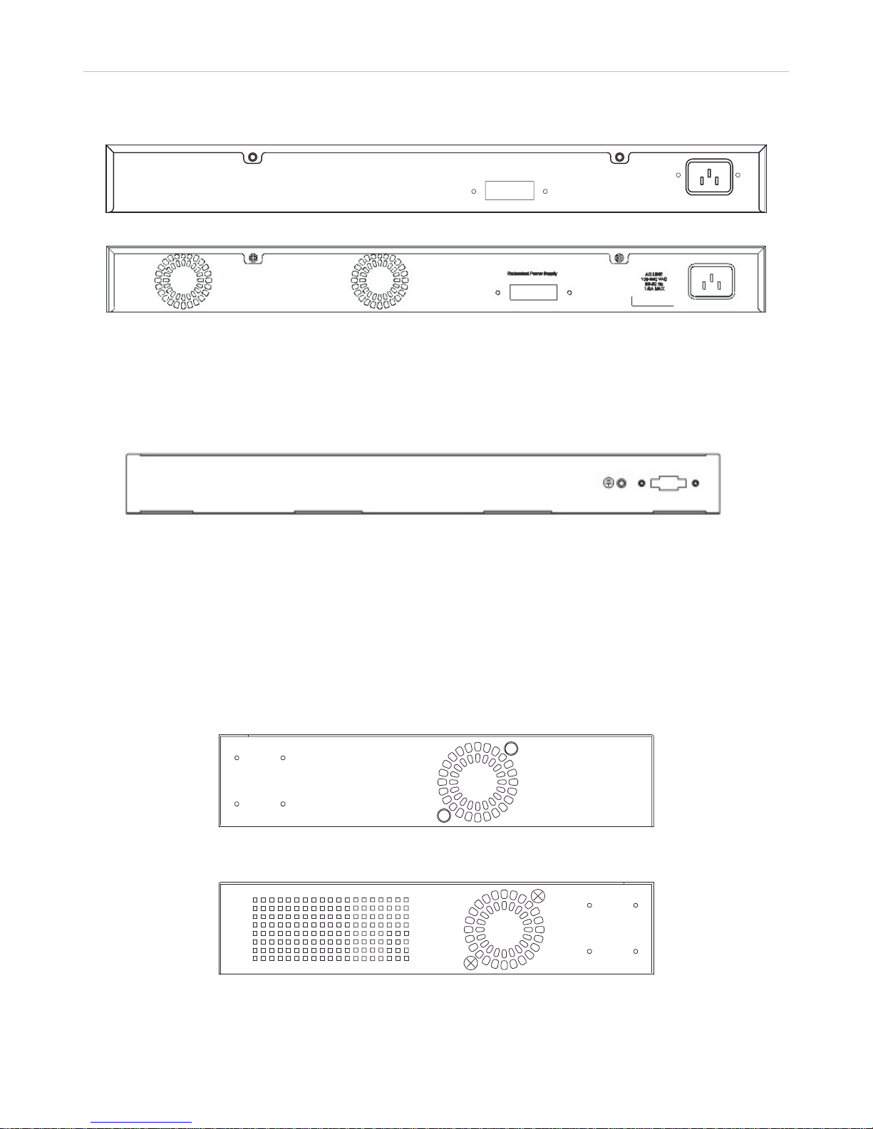
Rear Panel Description
The rear panel of the Switch contains an AC power connector.
Figure 1- 6. Rear panel view of the DES-3526
Figure 1- 7. Rear panel view of the DES-3550
The AC power connector is a standard three-pronged connector that suppor ts the power cord. Plug-in the female connector of the
provided power cord into this socket, and the male side of the cord into a power ou tlet. The Switch automatically adju sts its power
setting to any supply voltage in the range from 100 ~ 240 VAC at 50 ~ 60 Hz.
The rear panel also includes an outlet for an optional external power supply. When power fails, the optional external RPS will take
over all the power immediately and automatically.
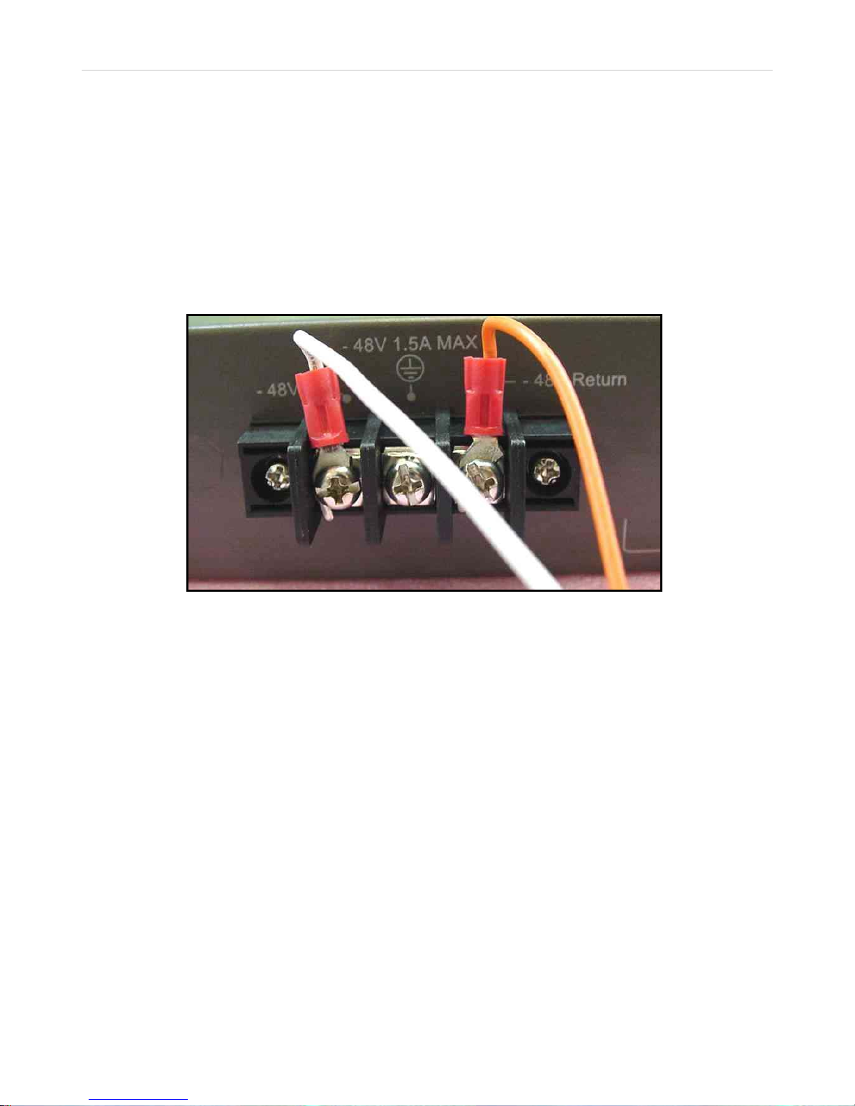
Figure 1- 8. Rear panel view of DES-3526DC
The rear panel of the DC power version of the Switch includes an opening designed to accommodate the DC power wiring
assembly. See the installation instructions in this Section for details.
Side Panel Description
The right-hand side panel of the Switch contains a system fan, while the left hand panel includes a system fan and a heat vent.
The system fans are used to dissipate heat. The sides of the system also provide heat vents to serve the same purpose. Do not
block these openings, and leave at least 6 inches of space at the rear and sides of the Switch for proper ventilation. Be reminded
that without proper heat dissipation and air circulation, system components might overheat, which could lead to system failure.
Figure 1- 9. Side panels of the DES-3526/DES-3526DC
xStack DES-3500 Series Layer 2 Stackable Fast Ethernet Managed Switch User Manual
5
Figure 1- 10. Side panels of the DES-3550
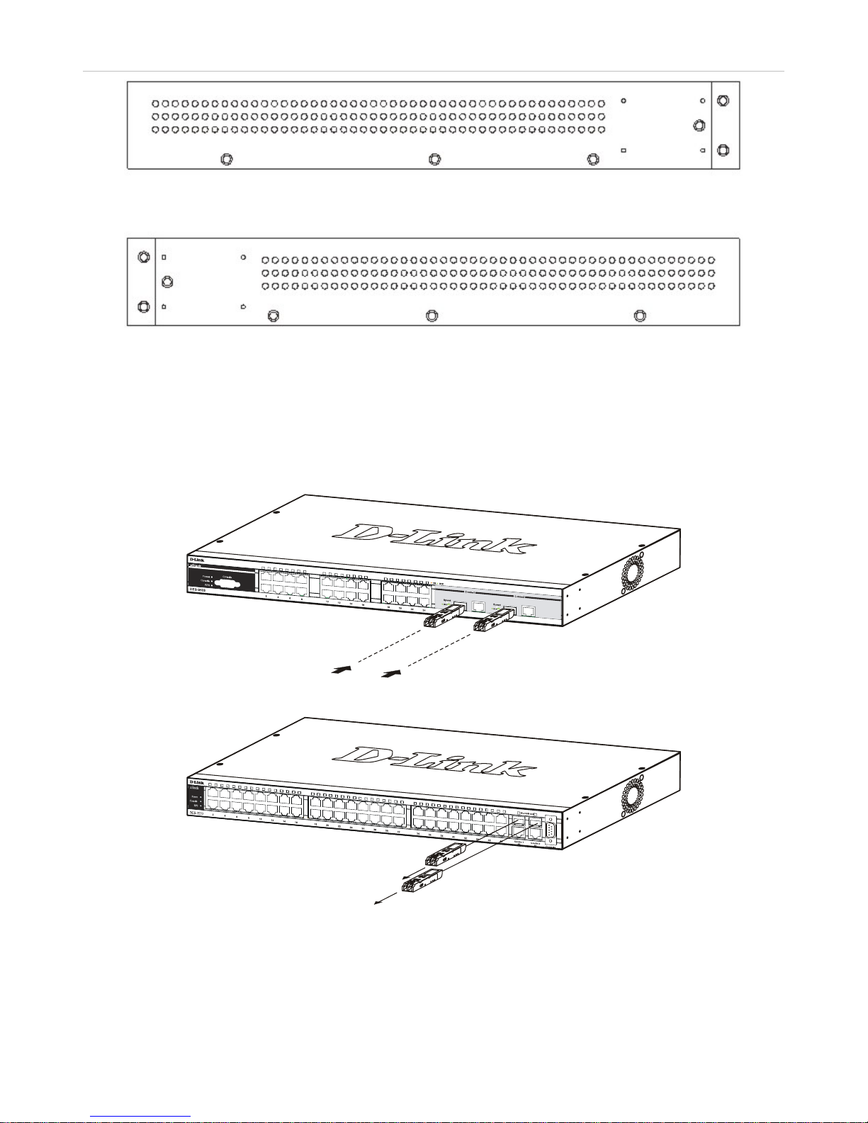
Gigabit Combo Ports
In addition to the 24 (or 48) 10/100 Mbps ports, the Switch features two Gigabit Ethernet Co mbo ports. These two ports are
1000BASE-T copper ports (provided) and Mini-GBIC ports (optional). See the diagram below to view the two Mini-GBIC port
modules being plugged into the Switch. Please note that although these two front panel modules can be used simultaneously, the
ports must be different. The GBIC port will always have the highest priority.
Figure 1- 11. Inserting the Mini-GBIC modules into the DES-3526
Figure 1- 12. Inserting the Mini-GBIC modules into the DES-3550

xStack DES-3500 Series Layer 2 Stackable Fast Ethernet Managed Switch User Manual
6
Figure 1- 13. Installing the Mini-GBIC Module

xStack DES-3500 Series Layer 2 Stackable Fast Ethernet Managed Switch User Manual
7
SECTION 2
Installation
Package Contents
Before You Connect to the Network
Installing the Switch without the Rack
Rack Installation
Power On
Package Contents
Open the shipping carton of the Switch and carefully unpack its contents. The carton should contain the following items:
• One xStack DES-3500 Series stand-alone switch
• One AC power cord
• This manual
• Registration card
• Mounting kit (two brackets and screws)
• Four rubber feet with adhesive backing
• RS-232 console cable
If any item is found missing or damaged, please contact your local D-Link Reseller for replacement.
Before You Connect to the Network
The site where you install the Switch may greatly affect its performance. Please follow these guidelines for setting up the Switch.
• Install the Switch on a sturdy, level surface that can support at least 6.6 lb. (3 kg) of weight. Do not place heavy objects
on the Switch.
• The power outlet should be within 1.82 m et e rs (6 feet) of the Swit ch .
• Visually inspect the power cord and see that it is fully secured to the AC power port.
• Make sure that there is proper heat dissipation from and adequate ventilation around the Switch. Leave at least 10 cm (4
inches) of space at the front and rear of the Switch for ventilation.
• Install the Switch in a fairly cool and dry place for the acceptable temperature and humidity operating ranges.
• Install the Switch in a site free from strong electromagnetic field generators (such as motors), vibration, dust, and direct
exposure to sunlight.
• When installing the Switch on a level surface, attach the rubber feet to the bottom of the device. The rubber feet
cushion the Switch, protect the casing from scratches and prevent it from scratching other surfaces.
xStack DES-3500 Series Layer 2 Stackable Fast Ethernet Managed Switch User Manual
8
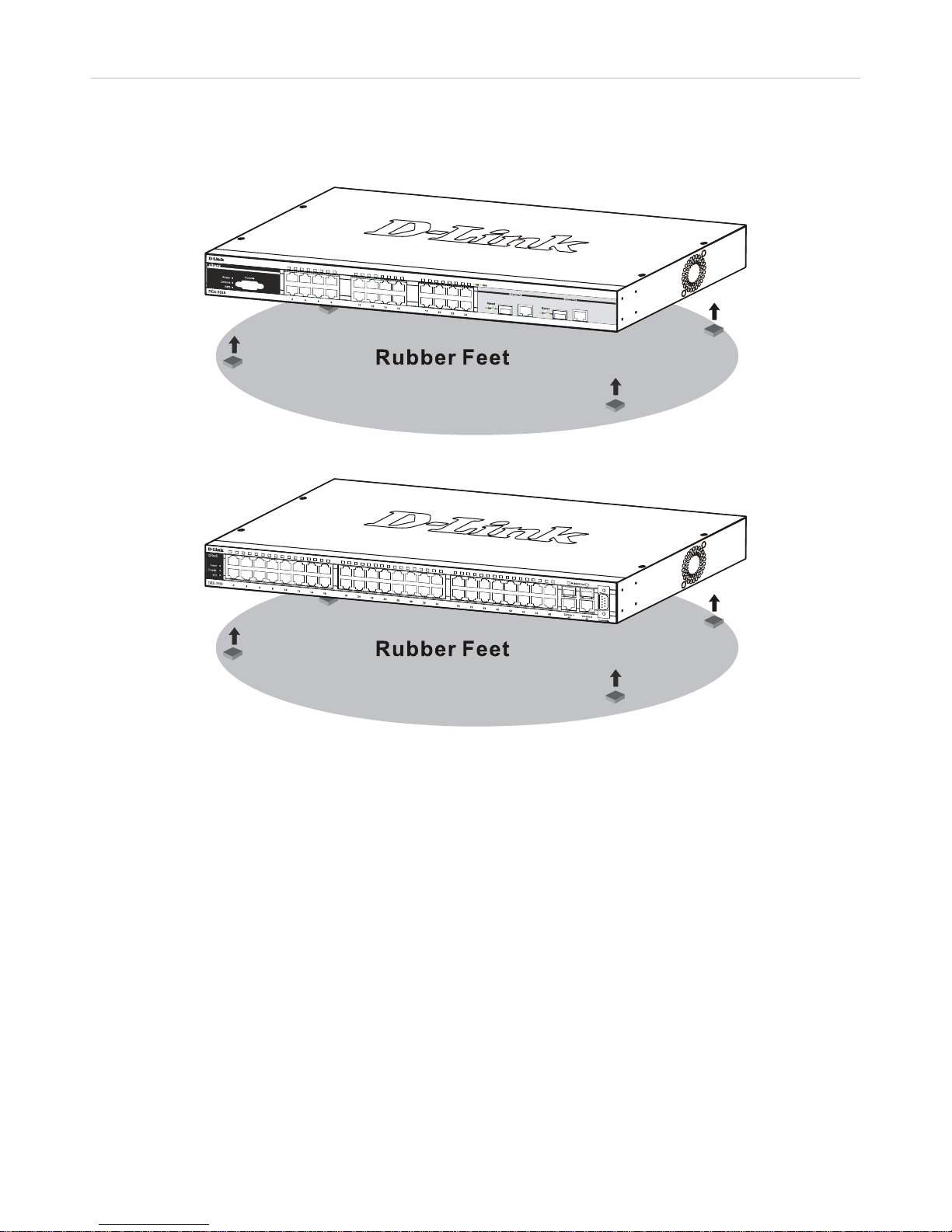
Installing the Switch without the Rack
When installing the Switch on a desktop or shelf, the rubber feet included with the Switch should first be attached. Attach these
cushioning feet on the bottom at each corner of the device. Allow enough ventilation space between the Switch and any other
objects in the vicinity.
Figure 2- 1. Preparing the DES-3526 for installation on a desktop or shelf
Figure 1- 14. Preparing the DES-3550 for installation on a desktop or shelf
xStack DES-3500 Series Layer 2 Stackable Fast Ethernet Managed Switch User Manual
9
Installing the Switch in a Rack
The Switch can be mounted in a standard 19" rack. Use the following diagrams to guide you.
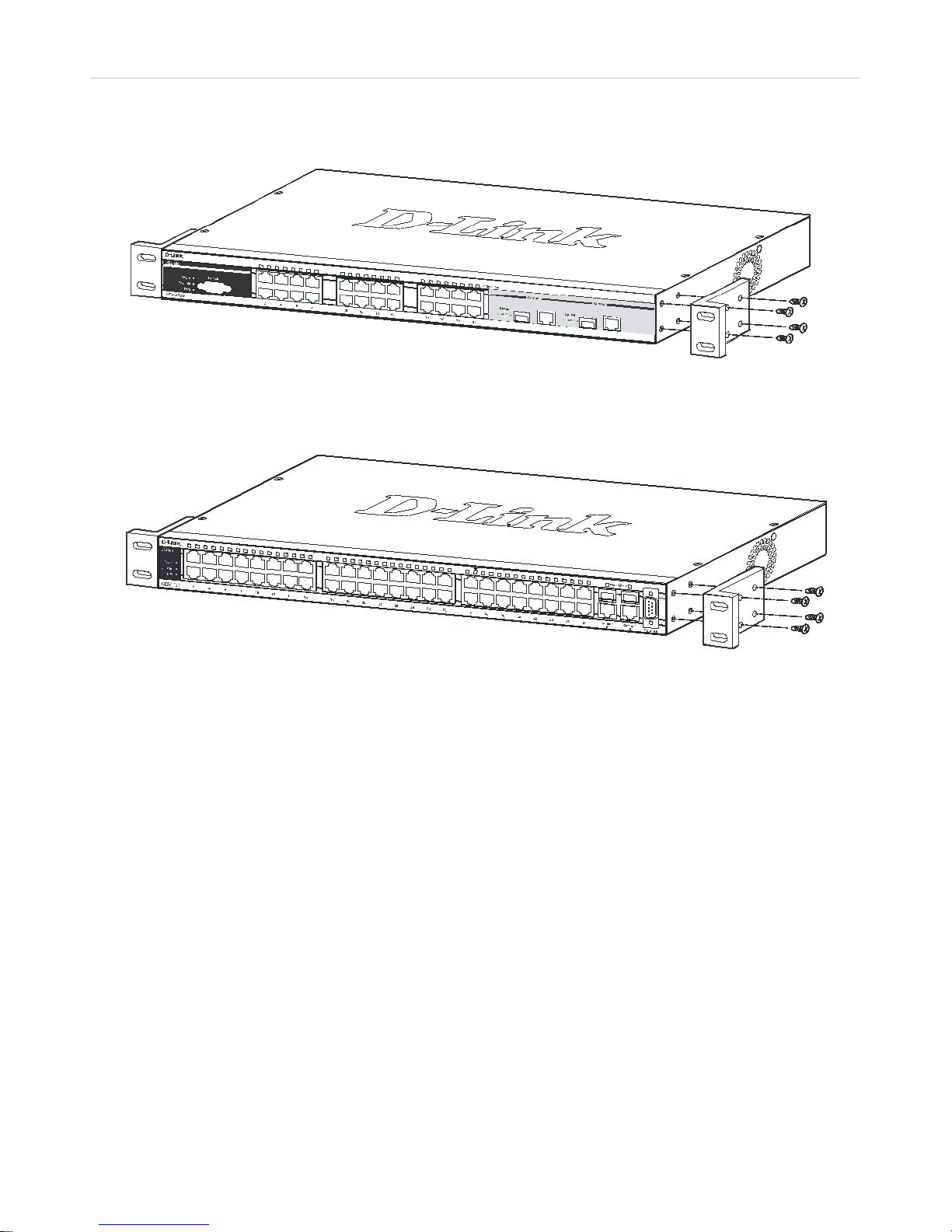
Figure 2- 2. Fasten mounting brackets to the DES-3526
Figure 1- 15. Fasten mounting brackets to the DES-3550
Fasten the mounting brackets to the Switch using the screws provided. W ith the brackets attached securely, you can mount the
Switch in a standard rack as shown in Figure 2-3 below.
xStack DES-3500 Series Layer 2 Stackable Fast Ethernet Managed Switch User Manual
10
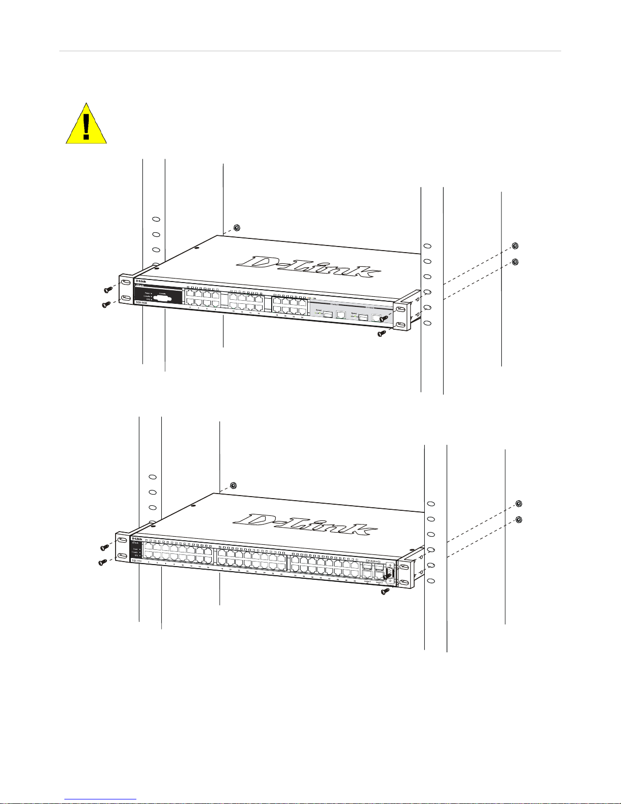
Mounting the Switch in a Standard 19" Rack
CAUTION: Installing systems in a rack without the front and side stabilizers installed could cause the
rack to tip over, potentially resulting in bodily injury under certain circumstances. Therefore, always
install the stabilizers before installing components in the rack. After installing components in a rack, do
not pull more than one component out of the rack on its slide assemblies at one time. The weight of
more than one extended component could cause the rack to tip over and may result in injury.
Figure 2- 3. Installing the DES-3526 in a rack
Figure 2- 4. Installing the DES-3550 in a rack
xStack DES-3500 Series Layer 2 Stackable Fast Ethernet Managed Switch User Manual
11
Power On (AC Power)
Plug one end of the AC power cord into the power connector of the Switch and the other end into the local power source outlet.
After the Switch is powered on, the LED indicators will momentarily blink. This blinking of the LED indicators represents a reset
of the system.
Power Failure
As a precaution for AC power supply units, in the event of a power failure, unplug the Switch. When power has resumed, plug the
Switch back in.
Connecting DC Power to DES-3526DC
Follow the instructions below to connect the DC power supply of the DES-352 6DC to a DC power source.
Figure 2- 5. Power connections attached to contacts on assembly
1. Firmly attach the DC power to the negative and positive contacts on the wiring assembly.
• The negative pole (-) connects to the -48V contact.
• The positive pole (+) connects to the -48V Return contact.
• If available, the earth ground may be connected to center contact post.
2. Tighten the contact screws so the connection is secure.
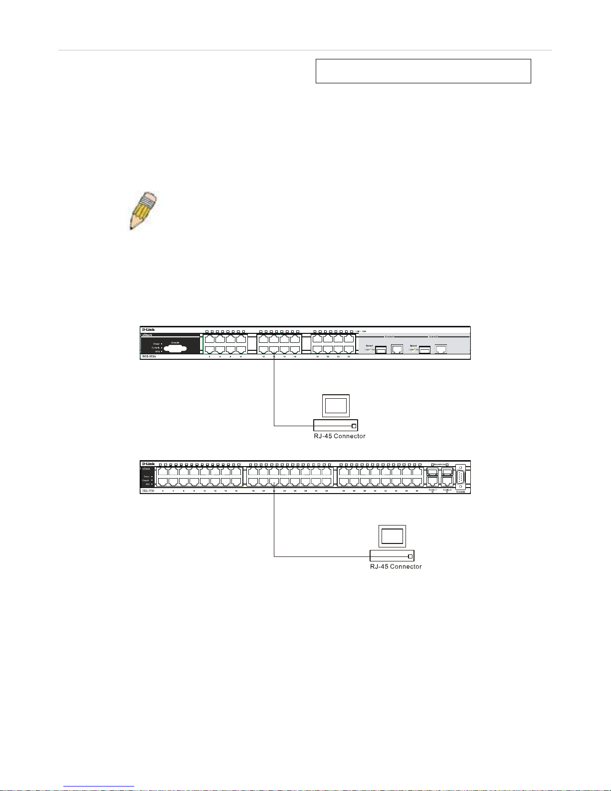
xStack DES-3500 Series Layer 2 Stackable Fast Ethernet Managed Switch User Manual
12
Section 3
Connecting the Switch
Switch to End Node
Switch to Hub or Switch
Connecting To Network Backbone or Server
NOTE: All 24 (48 for the DES-3550) high-performance NWay Ethernet
ports can support both MDI-II and MDI-X connections.
Switch to End Node
End nodes include PCs outfitted with a 10, 100 or 1000 Mbps RJ-45 Ethernet/Fast Ethernet Network Interface Card (NIC) and
most routers.
An end node can be connected to the Switch via a twisted-pair Category 3, 4, or 5 UTP/STP cable. The end node should be
connected to any of the ports of the Switch.
Figure 3- 1. DES-3526 connected to an end node
Figure 2- 6. DES-3550 connected to an end node
The Link/Act LEDs for each UTP port will light green or amber when the link is valid. A blinking LED indicates packet activity
on that port.
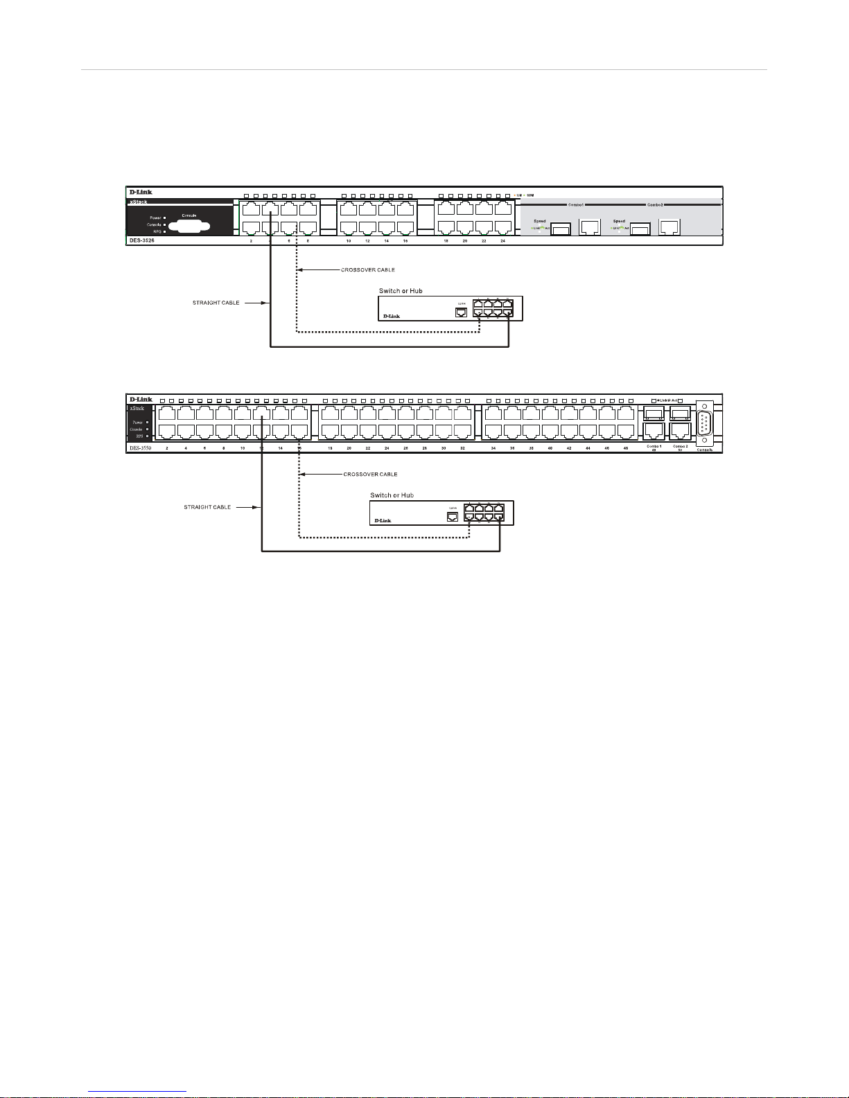
xStack DES-3500 Series Layer 2 Stackable Fast Ethernet Managed Switch User Manual
13
Switch to Hub or Switch
These connections can be accomplished in a number of ways using a normal cable.
• A 10BASE-T hub or switch can be connected to the Switch via a twisted-pair Category 3, 4 or 5 UTP/STP cable.
• A 100BASE-TX hub or switch can be connected to the Switch via a twisted -pair Category 5 UTP/STP cable.
Figure 3- 2. DES-3526 connected to a normal (non-Uplink) port on a hub or switch using a straight or
crossover cable
Figure 2- 7. DES-3550 connected to a normal (non-Uplink) port on a hub or switch using a straight or
crossover cable
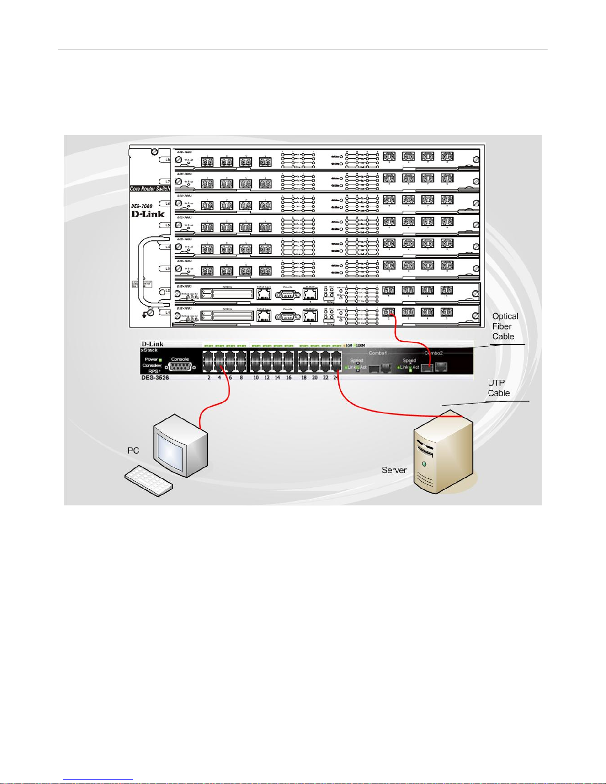
xStack DES-3500 Series Layer 2 Stackable Fast Ethernet Managed Switch User Manual
14
Connecting To Network Backbone or Server
The two Mini-GBIC combo ports are ideal for unlinking to a network backbone or server. The copper ports operate at a speed of
1000, 100 or 10Mbps in full or half duplex mode. The fiber optic ports can operate at 1000Mbps in full duplex mode.
Connections to the Gigabit Ethernet ports are made using fiber optic cable or Category 5 copper cable, depending on the type of
port. A valid connection is indicated when the Link LED is lit.
Figure 3- 3. Connecting the DES-3500 Series switch to a Server

xStack DES-3500 Series Layer 2 Stackable Fast Ethernet Managed Switch User Manual
15
Section 4
Introduction to Switch Management
Management Options
Web-based Management Interface
SNMP-Based Management
Managing User Accounts
Command Line Console Interface through the Serial Port
Connecting the Console Port (RS-232 DCE)
First Time Connecting to the Switch
Password Protection
SNMP Settings
IP Address Assignment
Connecting Devices to the Switch
Management Options
This system may be managed out-of-band through the console port on the front panel or in-band using Telnet. The user may also
choose the web-based management, accessible through a web browser.
Web-based Management Interface
After you have successfully installed the Switch, you can configure the Switch, monitor the LED panel, and display statistics
graphically using a web browser, such as Netscape Navigator (version 6.2 and higher) or Microsoft® Internet Explorer (version
5.0).
SNMP-Based Management
You can manage the Switch with an SNMP-compatible console program. The Switch supports SNMP version 1.0, version 2.0 and
version 3.0. The SNMP agent decodes the incoming SNMP messages and responds to requests with MIB objects stored in the
database. The SNMP agent updates the MIB objects to generate statistics and counters.
Connecting the Console Port (RS-232 DCE)
The Switch provides an RS-232 serial port that enables a connection to a computer or terminal for monitoring and configuring the
Switch. This port is a female DB-9 connector, implemented as a data terminal equipment (DTE) connection.
To use the console port, you need the following equipment:
• A terminal or a computer with both a serial port and the ability to emulate a terminal.
• A null modem or crossover RS-232 cable with a female DB-9 connector for the console port on the Switch.

xStack DES-3500 Series Layer 2 Stackable Fast Ethernet Managed Switch User Manual
16
To connect a terminal to the console port:
1. Connect the female connector of the RS-232 cab le directly to the console port on the Switch, and tighten the captive
retaining screws.
2. Connect the other end of the cable to a terminal or to the serial connector of a computer running terminal emulation
software. Set the terminal emulation software as follows:
3. Select the appropriate serial port (COM port 1 or COM port 2).
4. Set the data rate to 9600 baud.
5. Set the data format to 8 data bits, 1 stop bit, and no parity.
6. Set flow control to none.
7. Under Properties, select VT100 for Emulation mode.
8. Select Terminal keys for Function, Arrow, and Ctrl keys. Ensure that you select Terminal keys (not Windows keys).
9. After you have correctly set up the terminal, plug the power cable into the power receptacle on the back of the Switch.
The boot sequence appears in the terminal.
10. After the boot sequence completes, the console login screen displays.
11. If you have not logged into the command line interface (CLI) program, press the Enter key at the User name and
password prompts. There is no default user name and password for the Switch. The administrator must first create user
names and passwords. If you have previously set up user accounts, log in and continue to configure the Switch.
12. Enter the commands to complete your desired tasks. Many commands require administrator-level access privileges. Read
the next section for more information on setting up user accounts. See the DES-3500 Series switches Command Line
Interface Reference Manual on the documentation CD for a list of all commands and additional information on using
the CLI.
13. When you have completed your tasks, exit the session with the logout command or close the emulator program.
Make sure the terminal or PC you are using to make this connection is configured to match these settings.
If you are having problems making this connection on a PC, make sure the emulation is set to VT-100. You will be able to set the
emulation by clicking on the File menu in you HyperTerminal window, clicking on Properties in the drop-down menu, and then
clicking the Settings tab. This is where you will find the Emulation options. If you still do not see anything, try rebooting the
Switch by disconnecting its powe r su ppl y .
Once connected to the console, the screen below will appear on your console screen. This is where the user will en ter commands
to perform all the available management functions. The Switch will prompt the user to enter a user name and a password. Upon
the initial connection, there is no user name or password and therefore just press enter twice to access the command line interface.
Figure 4- 1. Initial screen after first connection
NOTE: When you use HyperTerminal with the Microsoft® Windows® 2000 operating sys-
tem, ensure that you have Windows 2000 Service Pack 2 or later installed. Windows 2000
Service Pack 2 allows you to use arrow keys in HyperTerminal's VT100 emulation. See
www.microsoft.com for information on Windows 2000 service packs.
 Loading...