

D-Link DES-3326SR User Manual

DES-3326SR
Layer 3 Switch
User’s Guide
First Edition (May 2003)
6513326SR015
Printed In Taiwan
RECYCLABLE

Wichtige Sicherheitshinweise
1. Bitte lesen Sie sich diese Hinweise sorgfältig durch.
2. Heben Sie diese Anleitung für den spätern Gebrauch auf.
3. Vor jedem Reinigen ist das Gerät vom Stromnetz zu trennen. Vervenden Sie keine
Flüssig- oder Aerosolreiniger. Am besten dient ein angefeuchtetes Tuch zur
Reinigung.
4. Um eine Beschädigung des Gerätes zu vermeiden sollten Sie nur Zubehörteile
verwenden, die vom Hersteller zugelassen sind.
5. Das Gerät is vor Feuchtigkeit zu schützen.
6. Bei der Aufstellung des Gerätes ist auf sichern Stand zu achten. Ein Kippen oder
Fallen könnte Verletzungen hervorrufen. Verwenden Sie nur sichere Standorte und
beachten Sie die Aufstellhinweise des Herstellers.
7. Die Belüftungsöffnungen dienen zur Luftzirkulation die das Gerät vor Überhitzung
schützt. Sorgen Sie dafür, daß diese Öffnungen nicht abgedeckt werden.
8. Beachten Sie beim Anschluß an das Stromnetz die Anschlußwerte.
9. Die Netzanschlußsteckdose muß aus Gründen der elektrischen Sicherheit einen
Schutzleiterkontakt haben.
10. Verlegen Sie die Netzanschlußleitung so, daß niemand darüber fallen kann. Es sollete
auch nichts auf der Leitung abgestellt werden.
11. Alle Hinweise und Warnungen die sich am Geräten befinden sind zu beachten.
12. Wird das Gerät über einen längeren Zeitraum nicht benutzt, sollten Sie es vom
Stromnetz trennen. Somit wird im Falle einer Überspannung eine Beschädigung
vermieden.
13. Durch die Lüftungsöffnungen dürfen niemals Gegenstände oder Flüssigkeiten in das
Gerät gelangen. Dies könnte einen Brand bzw. Elektrischen Schlag auslösen.
14. Öffnen Sie niemals das Gerät. Das Gerät darf aus Gründen der elektrischen
Sicherheit nur von authorisiertem Servicepersonal geöffnet werden.
15. Wenn folgende Situationen auftreten ist das Gerät vom Stromnetz zu trennen und von
einer qualifizierten Servicestelle zu überprüfen:
a – Netzkabel oder Netzstecker sint beschädigt.
b – Flüssigkeit ist in das Gerät eingedrungen.
c – Das Gerät war Feuchtigkeit ausgesetzt.
d – Wenn das Gerät nicht der Bedienungsanleitung ensprechend funktioniert oder Sie
mit Hilfe dieser Anleitung keine Verbesserung erzielen.
e – Das Gerät ist gefallen und/oder das Gehäuse ist beschädigt.
f – Wenn das Gerät deutliche Anzeichen eines Defektes aufweist.
16. Bei Reparaturen dürfen nur Orginalersatzteile bzw. den Orginalteilen entsprechende
Teile verwendet werden. Der Einsatz von ungeeigneten Ersatzteilen kann eine weitere
Beschädigung hervorrufen.
17. Wenden Sie sich mit allen Fragen die Service und Repartur betreffen an Ihren
Servicepartner. Somit stellen Sie die Betriebssicherheit des Gerätes sicher.
ii

18. Zum Netzanschluß dieses Gerätes ist eine geprüfte Leitung zu verwenden, Für einen
Nennstrom bis 6A und einem Gerätegewicht grőßer 3kg ist eine Leitung nicht leichter
als H05VV-F, 3G, 0.75mm2 einzusetzen.

WARRANTIES EXCLUSIVE
IF THE D-LINK PRODUCT DOES NOT OPERATE AS WARRANTED ABOVE, THE
CUSTOMER'S SOLE REMEDY SHALL BE, AT D-LINK'S OPTION, REPAIR OR
REPLACEMENT. THE FOREGOING WARRANTIES AND REMEDIES ARE EXCLUSIVE AND
ARE IN LIEU OF ALL OTHER WARRANTIES, EXPRESSED OR IMPLIED, EITHER IN FACT
OR BY OPERATION OF LAW, STATUTORY OR OTHERWISE, INCLUDING WARRANTIES
OF MERCHANTABILITY AND FITNESS FOR A PARTICULAR PURPOSE. D-LINK NEITHER
ASSUMES NOR AUTHORIZES ANY OTHER PERSON TO ASSUME FOR IT ANY OTHER
LIABILITY IN CONNECTION WITH THE SALE, INSTALLATION MAINTENANCE OR USE OF
D-LINK'S PRODUCTS
D-LINK SHALL NOT BE LIABLE UNDER THIS WARRANTY IF ITS TESTING AND
EXAMINATION DISCLOSE THAT THE ALLEGED DEFECT IN THE PRODUCT DOES NOT
EXIST OR WAS CAUSED BY THE CUSTOMER'S OR ANY THIRD PERSON'S MISUSE,
NEGLECT, IMPROPER INSTALLATION OR TESTING, UNAUTHORIZED ATTEMPTS TO
REPAIR, OR ANY OTHER CAUSE BEYOND THE RANGE OF THE INTENDED USE, OR BY
ACCIDENT, FIRE, LIGHTNING OR OTHER HAZARD.
LIMITATION OF LIABILITY
IN NO EVENT WILL D-LINK BE LIABLE FOR ANY DAMAGES, INCLUDING LOSS OF
DATA, LOSS OF PROFITS, COST OF COVER OR OTHER INCIDENTAL, CONSEQUENTIAL
OR INDIRECT DAMAGES ARISING OUT THE INSTALLATION, MAINTENANCE, USE,
PERFORMANCE, FAILURE OR INTERRUPTION OF A D- LINK PRODUCT, HOWEVER
CAUSED AND ON ANY THEORY OF LIABILITY. THIS LIMITATION WILL APPLY EVEN IF
D-LINK HAS BEEN ADVISED OF THE POSSIBILITY OF SUCH DAMAGE.
IF YOU PURCHASED A D-LINK PRODUCT IN THE UNITED STATES, SOME STATES DO
NOT ALLOW THE LIMITATION OR EXCLUSION OF LIABILITY FOR INCIDENTAL OR
CONSEQUENTIAL DAMAGES, SO THE ABOVE LIMITATION MAY NOT APPLY TO YOU.
Limited Warranty
Hardware:
D-Link warrants each of its hardware products to be free from defects in workmanship
and materials under normal use and service for a period commencing on the date of
purchase from D-Link or its Authorized Reseller and extending for the length of time
stipulated by the Authorized Reseller or D-Link Branch Office nearest to the place of
purchase.
This Warranty applies on the condition that the product Registration Card is filled out and
returned to a D-Link office within ninety (90) days of purchase. A list of D-Link offices is
provided at the back of this manual, together with a copy of the Registration Card.
If the product proves defective within the applicable warranty period, D-Link will provide
repair or replacement of the product. D-Link shall have the sole discretion whether to
repair or replace, and replacement product may be new or reconditioned. Replacement
product shall be of equivalent or better specifications, relative to the defective product, but
need not be identical. Any product or part repaired by D-Link pursuant to this warranty
shall have a warranty period of not less than 90 days, from date of such repair,
iv

irrespective of any earlier expiration of original warranty period. When D-Link provides
replacement, then the defective product becomes the property of D-Link.
Warranty service may be obtained by contacting a D-Link office within the applicable
warranty period, and requesting a Return Material Authorization (RMA) number. If a
Registration Card for the product in question has not been returned to D-Link, then a
proof of purchase (such as a copy of the dated purchase invoice) must be provided. If
Purchaser's circumstances require special handling of warranty correction, then at the
time of requesting RMA number, Purchaser may also propose special procedure as may be
suitable to the case.
After an RMA number is issued, the defective product must be packaged securely in the
original or other suitable shipping package to ensure that it will not be damaged in
transit, and the RMA number must be prominently marked on the outside of the package.
The package must be mailed or otherwise shipped to D-Link with all costs of
mailing/shipping/insurance prepaid. D-Link shall never be responsible for any software,
firmware, information, or memory data of Purchaser contained in, stored on, or integrated
with any product returned to D-Link pursuant to this warranty.
Any package returned to D-Link without an RMA number will be rejected and shipped
back to Purchaser at Purchaser's expense, and D-Link reserves the right in such a case to
levy a reasonable handling charge in addition mailing or shipping costs.
Software:
Warranty service for software products may be obtained by contacting a D-Link office
within the applicable warranty period. A list of D-Link offices is provided at the back of
this manual, together with a copy of the Registration Card. If a Registration Card for the
product in question has not been returned to a D-Link office, then a proof of purchase
(such as a copy of the dated purchase invoice) must be provided when requesting
warranty service. The term "purchase" in this software warranty refers to the purchase
transaction and resulting license to use such software.
D-Link warrants that its software products will perform in substantial conformance with
the applicable product documentation provided by D-Link with such software product, for
a period of ninety (90) days from the date of purchase from D-Link or its Authorized
Reseller. D-Link warrants the magnetic media, on which D-Link provides its software
product, against failure during the same warranty period. This warranty applies to
purchased software, and to replacement software provided by D-Link pursuant to this
warranty, but shall not apply to any update or replacement which may be provided for
download via the Internet, or to any update which may otherwise be provided free of
charge.
D-Link's sole obligation under this software warranty shall be to replace any defective
software product with product which substantially conforms to D-Link's applicable
product documentation. Purchaser assumes responsibility for the selection of appropriate
application and system/platform software and associated reference materials. D-Link
makes no warranty that its software products will work in combination with any
hardware, or any application or system/platform software product provided by any third
party, excepting only such products as are expressly represented, in D-Link's applicable
product documentation as being compatible. D-Link's obligation under this warranty
shall be a reasonable effort to provide compatibility, but D-Link shall have no obligation to
provide compatibility when there is fault in the third-party hardware or software. D-Link
makes no warranty that operation of its software products will be uninterrupted or

absolutely error-free, and no warranty that all defects in the software product, within or
without the scope of D-Link's applicable product documentation, will be corrected.
vi

D-Link Offices for Registration and Warranty Service
The product's Registration Card, provided at the back of this manual, must be sent to a
D-Link office. To obtain an RMA number for warranty service as to a hardware product,
or to obtain warranty service as to a software product, contact the D-Link office nearest
you. An address/telephone/fax/e-mail/Web site list of D-Link offices is provided in the
back of this manual.
Trademarks
Copyright 2003 D-Link Corporation.
Contents subject to change without prior notice.
D-Link is a registered trademark of D-Link Corporation/D-Link
Systems, Inc. All other trademarks belong to their respective
proprietors.
Copyright Statement
No part of this publication may be reproduced in any form or by any
means or used to make any derivative such as translation,
transformation, or adaptation without permission from D-Link
Corporation/D-Link Systems Inc., as stipulated by the United States
Copyright Act of 1976.

FCC Warning
This equipment has been tested and found to comply with the limits
for a Class A digital device, pursuant to Part 15 of the FCC Rules.
These limits are designed to provide reasonable protection against
harmful interference when the equipment is operated in a commercial
environment. This equipment generates, uses, and can radiate radio
frequency energy and, if not installed and used in accordance with
this user’s guide, may cause harmful interference to radio
communications. Operation of this equipment in a residential area is
likely to cause harmful interference in which case the user will be
required to correct the interference at his own expense.
CE Mark Warning
This is a Class A product. In a domestic environment, this product
may cause radio interference in which case the user may be required
to take adequate measures.
VCCI Warning
viii

Table of Contents
Introduction ............................................................................1
Layer 3 Switching ................................................................. 1
Features ............................................................................... 2
Ports ..................................................................................2
Performance Features........................................................... 2
Redundant Power Supply ...................................................2
Layer 2 Features ................................................................3
Layer 3 Switch Features..................................................... 5
Traffic Classification and Prioritization ...............................6
Management ......................................................................6
Switch Stacking.................................................................... 7
Fast Ethernet Technology .....................................................8
Gigabit Ethernet Technology................................................. 8
Unpacking and Setup.............................................................. 9
Unpacking ............................................................................9
Installation ........................................................................... 9
Desktop or Shelf Installation ............................................ 10
Rack Installation.............................................................. 11
Power on............................................................................. 12
Power Failure ...................................................................13
Redundant Power Supply ................................................. 13
Identifying External Components ..........................................14
Front Panel.........................................................................14
Rear Panel .......................................................................... 15
Side Panels .........................................................................16
Optional Plug-in Modules ...................................................16
100BASE-FX Fiber Module (2Km/15Km) .........................17
1000BASE-T Module........................................................ 18
1000BASE-SX Fiber Module ............................................18
1000BASE-LX Fiber Module............................................. 19
GBIC Two-Port Module..................................................... 20
ix

Stacking Module with GBIC Port ......................................20
Switch LED Indicators ........................................................ 23
Stacking Module LED Indicators.........................................24
Connecting The Switch.......................................................... 25
Switch to End Node ............................................................25
Switch to Hub or Switch .....................................................26
Switch Stack Connections ..................................................27
10BASE-T Device ............................................................. 28
100BASE-TX Device......................................................... 29
Switch Management and Operating Concepts ....................... 30
Local Console Management ................................................30
Diagnostic (console) port (RS-232 DCE)............................ 31
Managing Switch Stacks..................................................... 32
Switch IP Address............................................................... 35
Traps.................................................................................. 37
SNMP .................................................................................38
MIBs................................................................................... 41
Packet Forwarding ..............................................................42
Filtering.............................................................................. 43
802.1w Rapid Spanning Tree ..............................................44
Link Aggregation.................................................................47
VLANs ................................................................................49
IP Addresses .......................................................................58
Internet Protocols ...............................................................67
Packet Headers................................................................... 74
The Domain Name System ..................................................81
DHCP Servers .....................................................................83
IP Routing ..........................................................................84
ARP ....................................................................................86
Multicasting .......................................................................87
Multicast Routing Protocols ................................................ 95
Routing Protocols ...............................................................97
Web-Based Switch Management.......................................... 143
Introduction .....................................................................143
Before You Start ...............................................................144
x

General Deployment Strategy......................................... 144
VLAN Layout ..................................................................145
Assigning IP Network Addresses and Subnet Masks to
VLANs............................................................................ 146
Defining Static Routes....................................................146
Getting Started ................................................................. 146
Management..................................................................... 147
Configuring the Switch .....................................................148
User Accounts Management........................................... 148
Saving Changes ................................................................ 150
Factory Reset....................................................................152
USING WEB-BASED MANAGEMENT ................................ 153
NETWORK MANAGEMENT ............................................... 181
SNMP Settings ...............................................................181
Advanced Setup................................................................196
Layer 3 IP Networking....................................................... 204
IP Multicasting .................................................................231
Port Mirroring................................................................... 246
Forwarding ....................................................................... 249
Configure QOS (Quality of Service).................................... 258
Bandwidth Control......................................................... 268
Spanning Tree ..................................................................269
MAC Notification............................................................... 276
Link Aggregation...............................................................279
802.1X Configuration .......................................................283
System Log Server ............................................................289
Utilities.............................................................................291
Network Monitoring ..........................................................302
Technical Specifications ...................................................... 332
Brief Review of Bitwise Logical Operations........................... 335
Index................................................................................... 337
xi


DES-3326SR Layer 3 Fast Ethernet Switch User’s Guide
1
INTRODUCTION
This section describes the functionality features of the DES3326SR. Some background information about Ethernet/Fast
Ethernet, Gigabit Ethernet, and switching technology is
presented.
Layer 3 Switching
Layer 3 switching is the integration of two proven technologies:
switching and routing. In fact, Layer 3 switches are running
the same routing routines and protocols as traditional routers.
The main difference between traditional routing and Layer 3
switching is the addition of a group of Layer 2 switching
domains and the execution of routing routines for most
packets via an ASIC – in hardware instead of software.
The DES-3326SR can also replace key traditional routers for
data centers and server farms, routing between these locations
and the rest of the network, and providing 24 ports of Layer 2
switching performance combined with wire-speed routing.
1

DES-3326SR Layer 3 Fast Ethernet Switch User’s Guide
Features
The DES-3326SR Switch was designed for easy installation
and high performance in an environment where traffic on the
network and the number of users increase continuously.
Switch features include:
Ports
24 high performance NWay ports all operating at 10/100 Mbps
with Auto-MDIX function for connecting to end stations,
servers and hubs.
• All ports can auto-negotiate (NWay) between 10Mbps/
100Mbps, half-duplex or full duplex and flow control for
half-duplex ports.
• One front panel slide-in module interface for a 2-port
1000BASE-SX, 1000BASE-LX, 1000BASE-T, 100BASE-FX,
GBIC or 1-port GBIC & Stack module.
• RS-232 DCE Diagnostic port (console port) for setting up
and managing the Switch via a connection to a console
terminal or PC using a terminal emulation program.
Performance Features
Redundant Power Supply
The DES-3326SR can be equipped with a redundant power
supply - the D-Link DPS-200 - to ensure continuation of
service if the main power unit fails. An integrated detection
2

DES-3326SR Layer 3 Fast Ethernet Switch User’s Guide
circuit continuously monitors the internal power supply. In the
event of a power interruption, the redundant power supply is
immediately triggered so that the DES-3326SR and connected
devices can continue providing service.
This results in a more reliable network infrastructure and
protects a network from a single failure of a network device
power supply.
The redundant power supply may be purchased with and
included in the original system installation, or may be added to
an existing system at a later time.
Layer 2 Features
• 8.8 Gbps switching fabric capacity
• Store and forward switching scheme.
• Full and half-duplex for both 10Mbps and 100Mbps
connections. The front-port Gigabit Ethernet module
operates at full-duplex only. Full-duplex allows the switch
port to simultaneously transmit and receive data, and only
works with connections to full-duplex capable end stations
and switches. Connections to hubs must take place at halfduplex.
• Supports IEEE 802.3x flow control for full-duplex mode
ports.
• Supports Back-pressure flow control for half-duplex mode
ports.
• Auto-polarity detection and correction of incorrect polarity
on the transmit and receive twisted-pair at each port.
• IEEE 802.3z compliant for all Gigabit ports (optional
module).
3

DES-3326SR Layer 3 Fast Ethernet Switch User’s Guide
• IEEE 802.3x compliant Flow Control support for all Gigabit
ports (optional module).
• IEEE 802.3ab compliant for 1000BASE-T (Copper) Gigabit
ports (optional module).
• Data forwarding rate 14,880 pps per port at 100% of wirespeed for 10Mbps speed.
• Data forwarding rate 148,800 pps per port at 100% of wirespeed for 100Mbps speed.
• Data filtering rate eliminates all error packets, runts, etc. at
14,880 pps per port at 100% of wire-speed for 10Mbps
speed.
• Data filtering rate eliminates all error packets, runts, etc. at
148,800 pps per port at 100% of wire-speed for 100Mbps
speed.
• 8K active MAC address entry table per device with
automatic learning and aging (10 to 9999 seconds).
• 8 MB packet buffer per device.
• Broadcast and Multicast storm filtering.
• Supports Port Mirroring.
• Supports Port Trunking – up to six trunk groups (each
consisting of up to eight ports) may be set up.
• 802.1D Spanning Tree support.
• 802.1Q Tagged VLAN support – up to 63 User-defined
VLANs per device (one VLAN is reserved for internal use).
• GVRP – (GARP VLAN Registration Protocol) support for
dynamic VLAN registration.
4

DES-3326SR Layer 3 Fast Ethernet Switch User’s Guide
• 802.1p Priority support with 4 priority queues.
• IGMP Snooping support.
Layer 3 Switch Features
• Wire speed IP forwarding.
• Hardware-based Layer 3 IP switching.
• IP packet forwarding rate of 6.6 Mpps.
• 2K active IP address entry table per device.
• Supports RIP – (Routing Information Protocol) version I and
II.
• Supports OSPF − (Open Shortest Path First)
• Supports MD5 and Password OSPF Packet Authentication
• Supports IP version 4.
• IGMP version 1 and 2 support (RFC 1112 and RFC 2236).
• Supports PIM Dense Mode.
• Supports DVMRP.
• Supports IP multi-netting.
• Supports IP packet de-fragmentation.
• Supports 802.1D frame support.
5

DES-3326SR Layer 3 Fast Ethernet Switch User’s Guide
Traffic Classification and Prioritization
• Based on 802.1p priority bits
• 4 priority queues
Management
• RS-232 console port for out-of-band network management
via a console terminal or PC.
• Spanning Tree Algorithm Protocol for creation of alternative
backup paths and prevention of network loops.
• SNMP v.1 Agent.
• Fully configurable either in-band or out-of-band control via
SNMP based software.
• Flash memory for software upgrades. This can be done inband via TFTP or out-of-band via the console.
• Built-in SNMP management:
• Bridge MIB (RFC 1493)
• MIB-II (RFC 1213)
• Mini-RMON MIB (RFC 1757) – 4 groups
• CIDR MIB (RFC 2096), except IP Forwarding Table.
• 802.1p MIB (RFC 2674).
• RIP MIB v2 (RFC 1724).
• IF MIB (RFC 2233)
6

DES-3326SR Layer 3 Fast Ethernet Switch User’s Guide
• Ether-Like MIB (RFC 1643)
• OSPF MIB (RFC 1850)
• Supports Web-based management.
• CLI management support
• TFTP support.
• BOOTP support.
• BOOTP Relay Agent.
• IP filtering on the management interface.
• DCHP Client support.
• DCHP Relay Agent.
• DNS Relay Agent.
• Password enabled.
Switch Stacking
The DES-3326SR can be used as a standalone or stacked
switch − using the optional stacking module. Up to 8 Switches
may be stacked and managed as a unit with a single IP
address.
Management for the entire stack is done through the Master
Switch.
You may add Switches later as needed.
7

DES-3326SR Layer 3 Fast Ethernet Switch User’s Guide
Fast Ethernet Technology
100Mbps Fast Ethernet (or 100BASE-T) is a standard specified
by the IEEE 802.3 LAN committee. It is an extension of the
10Mbps Ethernet standard with the ability to transmit and
receive data at 100Mbps, while maintaining the Carrier Sense
Multiple Access with Collision Detection (CSMA/CD) Ethernet
protocol.
Gigabit Ethernet Technology
Gigabit Ethernet is an extension of IEEE 802.3 Ethernet
utilizing the same packet structure, format, and support for
CSMA/CD protocol, full duplex, flow control, and management
objects, but with a tenfold increase in theoretical throughput
over 100Mbps Fast Ethernet and a one hundred-fold increase
over 10Mbps Ethernet. Since it is compatible with all 10Mbps
and 100Mbps Ethernet environments, Gigabit Ethernet
provides a straightforward upgrade without wasting a
company’s existing investment in hardware, software, and
trained personnel.
8

DES-3326SR Layer 3 Fast Ethernet Switch User’s Guide
2
UNPACKING AND SETUP
This chapter provides unpacking and setup information for the
Switch.
Unpacking
Open the shipping carton of the Switch and carefully unpack
its contents. The carton should contain the following items:
• One DES-3326SR 24-port Fast Ethernet Layer 3 Switch
• Mounting kit: 2 mounting brackets and screws
• Four rubber feet with adhesive backing
• One AC power cord
• This User’s Guide with Registration Card
If any item is found missing or damaged, please contact your
local D-Link reseller for replacement.
Installation
Use the following guidelines when choosing a place to install
the Switch:
9
DES-3326SR Layer 3 Fast Ethernet Switch User’s Guide
• The surface must support at least 3 kg (6.6 lb)
• The power outlet should be within 1.82 meters (6 feet) of
the device
• Visually inspect the power cord and see that it is secured to
the AC power connector
• Make sure that there is proper heat dissipation from and
adequate ventilation around the switch. Do not place heavy
objects on the switch
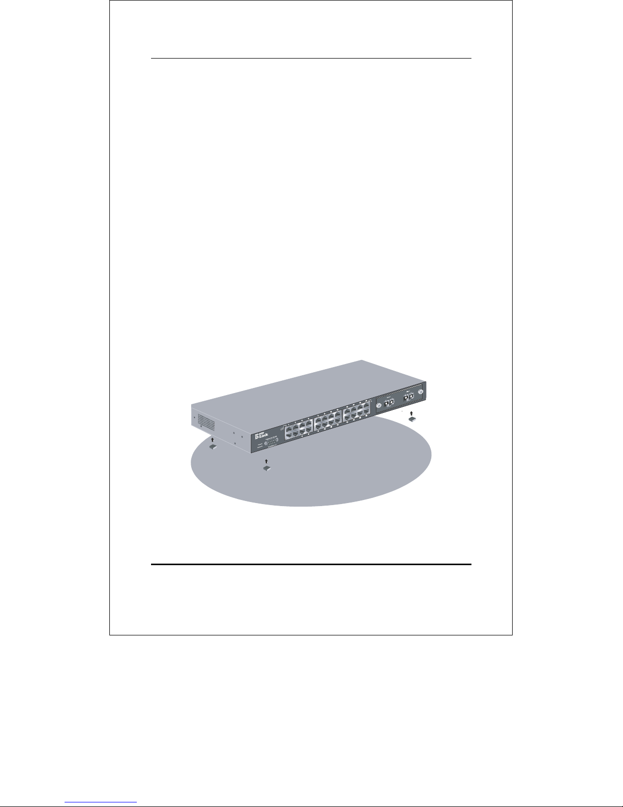
Desktop or Shelf Installation
When installing the Switch on a desktop or shelf, the rubber
feet included with the device should first be attached. Attach
these cushioning feet on the bottom at each corner of the
device. Allow adequate space for ventilation between the device
and the objects around it.
Figure 2-1. Installing rubber feet for desktop installation
10
DES-3326SR Layer 3 Fast Ethernet Switch User’s Guide
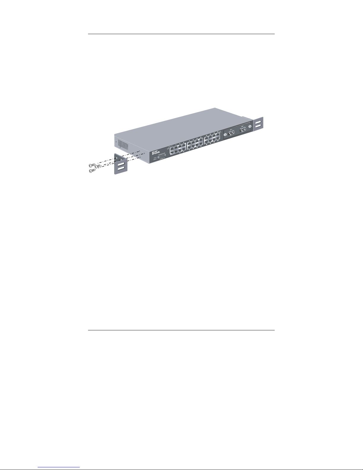
Rack Installation
The DES-3326SR can be mounted in an EIA standard-sized,
19-inch rack, which can be placed in a wiring closet with other
equipment. To install, attach the mounting brackets on the
switch’s side panels (one on each side) and secure them with
the screws provided.
Figure 2- 2. Attaching the mounting brackets to the switch
Then, use the screws provided with the equipment rack to
mount the switch on the rack.
11
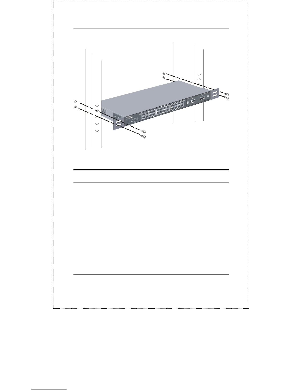
DES-3326SR Layer 3 Fast Ethernet Switch User’s Guide
Figure 2-3. Installing the switch on an equipment rack
Power on
The DES-3326SR switch can be used with AC power supply
100-240 VAC, 50 - 60 Hz. The power switch is located at the
rear of the unit adjacent to the AC power connector and the
system fan. The switch’s power supply will adjust to the local
power source automatically and may be turned on without
having any or all LAN segment cables connected.
After the power switch is turned on, the LED indicators should
respond as follows:
• All LED indicators will momentarily blink. This blinking of
the LED indicators represents a reset of the system
12

DES-3326SR Layer 3 Fast Ethernet Switch User’s Guide
• The power LED indicator is always on after the power is
turned ON
• The console LED indicator will blink while the Switch loads
onboard software and performs a self-test. will remain ON if
there is a connection at the RS-232 port, otherwise this
LED indicator is OFF
• The 100M LED indicator may remain ON or OFF depending
on the transmission speed
Power Failure
As a precaution in the event of a power failure, unplug the
switch. When the power supply is restored, plug the switch
back in.
Redundant Power Supply
The DES-3326SR can be equipped with a redundant power
supply - the D-Link DPS-200 - to ensure continuation of
service in a failure of the main power unit. An integrated
detection circuit continuously monitors the internal power
supply. In the event of a power interruption, the redundant
power supply is immediately triggered so that the DES-3326SR
and connected devices can continue providing service.
The redundant power supply may be purchased with and
included in the original system installation, or may be added to
an existing system at a later time.
13
DES-3326SR Layer 3 Fast Ethernet Switch User’s Guide
3
IDENTIFYING EXTERNAL
COMPONENTS
This chapter describes the front panel, rear panel, optional
plug-in modules, and LED indicators of the DES-3326SR.
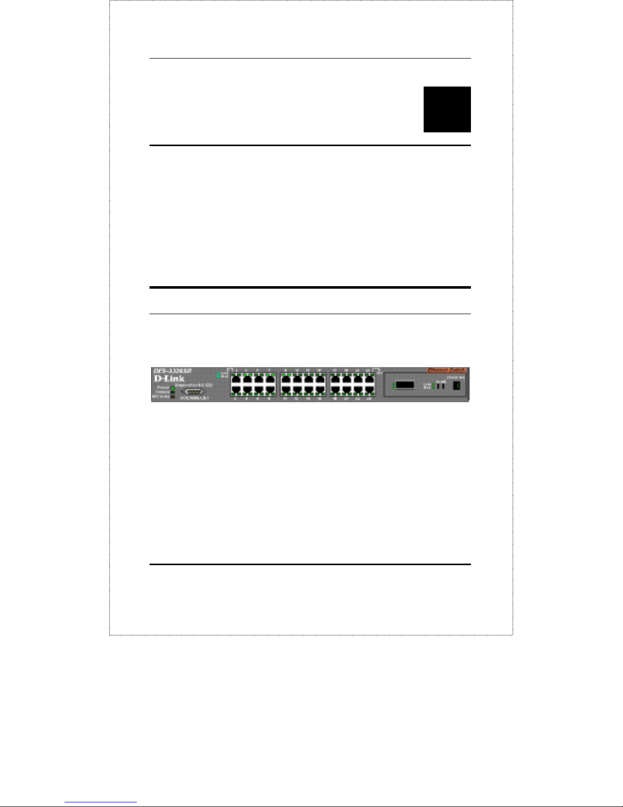
Front Panel
The front panel of the Switch consists of LED indicators, an
RS-232 communication port, a slide-in module slot, and 24
(10/100 Mbps) Ethernet/Fast Ethernet ports.
Figure 3-1. Front panel view of the Switch
• Comprehensive LED indicators display the status of the
switch and the network (see the LED Indicators section
below).
• An RS-232 DCE console port for setting up and managing
the switch via a connection to a console terminal or PC
using a terminal emulation program.
14
DES-3326SR Layer 3 Fast Ethernet Switch User’s Guide
• A front-panel slide-in module slot for Gigabit Ethernet ports
can accommodate a 2-port 1000BASE-T Gigabit Ethernet
module, a 2-port 1000BASE-SX Gigabit Ethernet module, a
2-port 1000BASE-LX Gigabit Ethernet module, or a 2-port
GBIC-based Gigabit Ethernet module.
• Twenty-four high-performance, NWay Ethernet ports all of
which operate at 10/100 Mbps with Auto-MDIX function for
connections to end stations, servers and hubs. All ports can
auto-negotiate between 10Mbps or 100Mbps, full or half
duplex, and flow control.
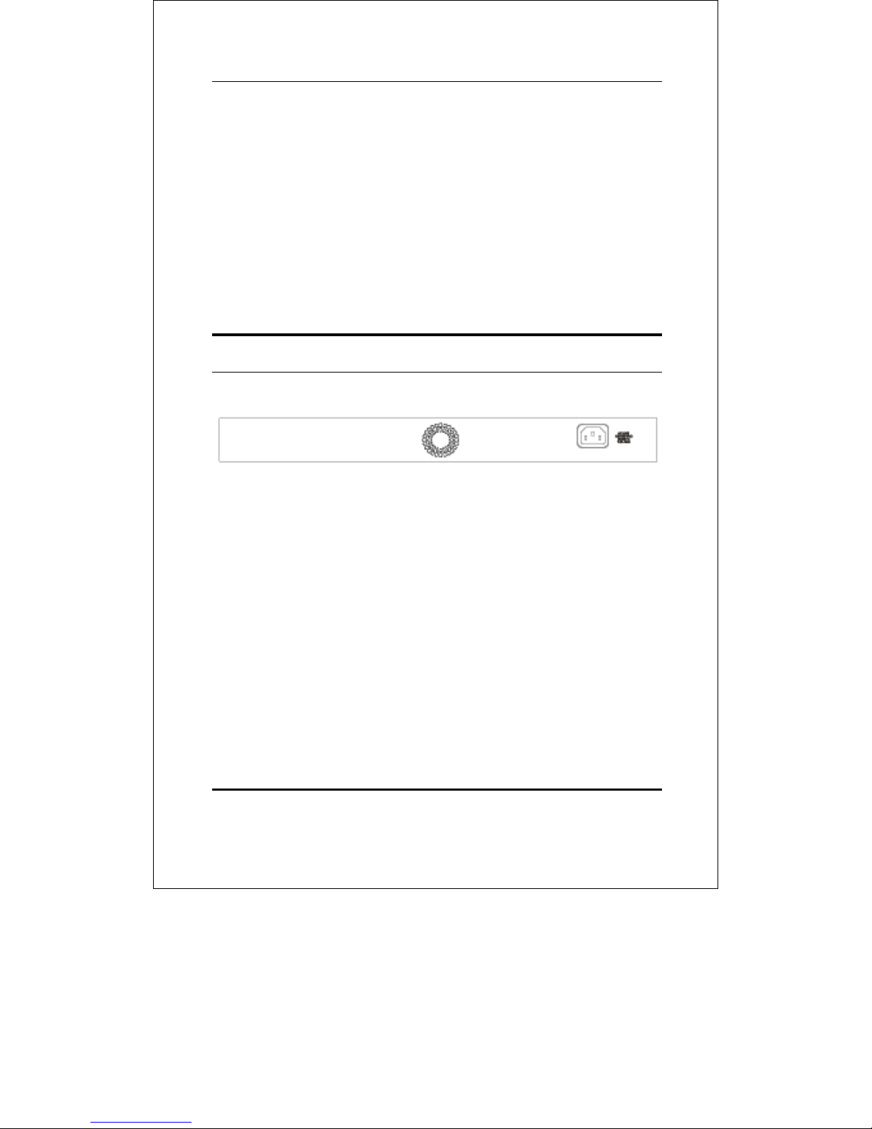
Rear Panel
The rear panel of the switch contains an AC power connector.
Figure 3-2. Rear panel view of the Switch
The AC power connector is a standard three-pronged connector
that supports the power cord. Plug-in the female connector of
the provided power cord into this socket, and the male side of
the cord into a power outlet. Supported input voltages range
from 100 ~ 240 VAC at 50 ~ 60 Hz.
Between the fan outlet and the power cord is the outlet for the
redundant power supply. Using the DPS-200 14-pin DC power
cable, connect the DES-3326SR to the DPS-200 redundant
power supply. The redundant power supply ensures that
service will not be interrupted in the event of an internal power
supply failure.
15
DES-3326SR Layer 3 Fast Ethernet Switch User’s Guide
For detailed instructions on connecting the DES-3326SR and
the DPS-200, please refer to the Redundant Power Supply
Quick Installation Guide supplied with your switch.
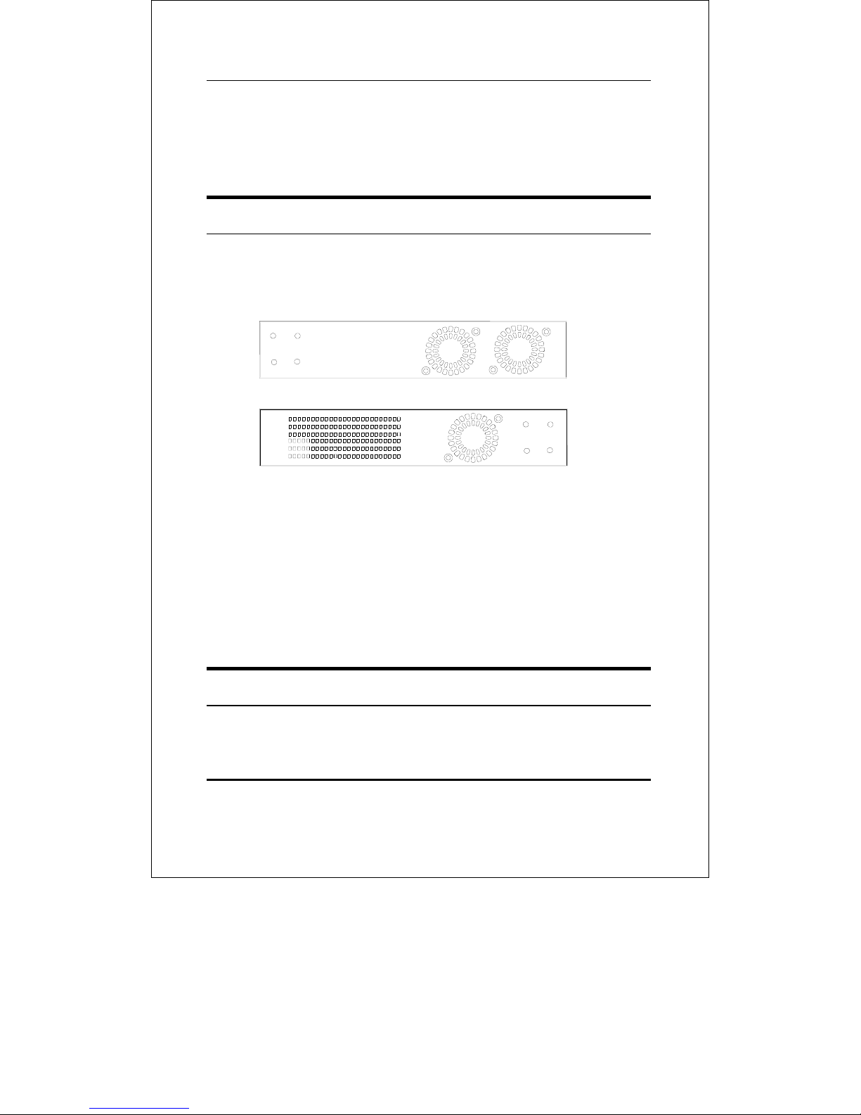
Side Panels
The right side panel of the Switch contains two system fans
(see the top part of the diagram below). The left side panel
contains heat vents.
Figure 3-4. Side panel views of the Switch
The system fans are used to dissipate heat. The sides of the
system also provide heat vents to serve the same purpose. Do
not block these openings, and leave at least 6 inches of space
at the rear and sides of the switch for proper ventilation. Be
reminded that without proper heat dissipation and air
circulation, system components might overheat, which could
lead to system failure.
Optional Plug-in Modules
The DES-3326SR 24-port Fast Ethernet Layer 3 Switch is able
to accommodate a range of optional plug-in modules in order to
16
DES-3326SR Layer 3 Fast Ethernet Switch User’s Guide
increase functionality and performance. These modules must
be purchased separately.
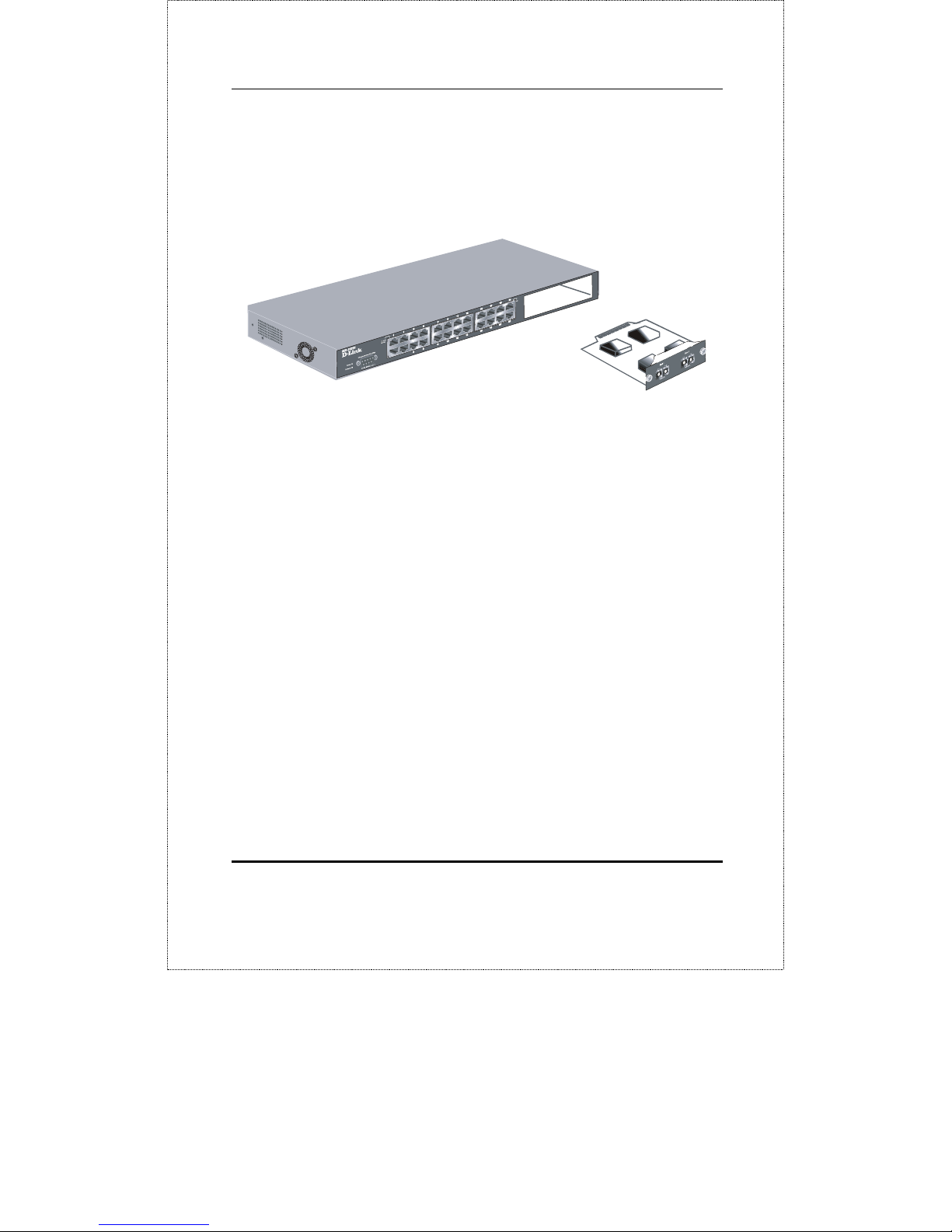
100BASE-FX Fiber Module (2Km/15Km)
Figure 3-5. 100BASE-FX two-port module
• Front-panel module.
• Two 100BASE-FX (with SC type connector) Fiber ports.
• Fully compliant with IEEE802.3u.
• Support Full-duplex operation only.
• IEEE 802.3x compliant Flow Control support for full-
duplex.
17
DES-3326SR Layer 3 Fast Ethernet Switch User’s Guide
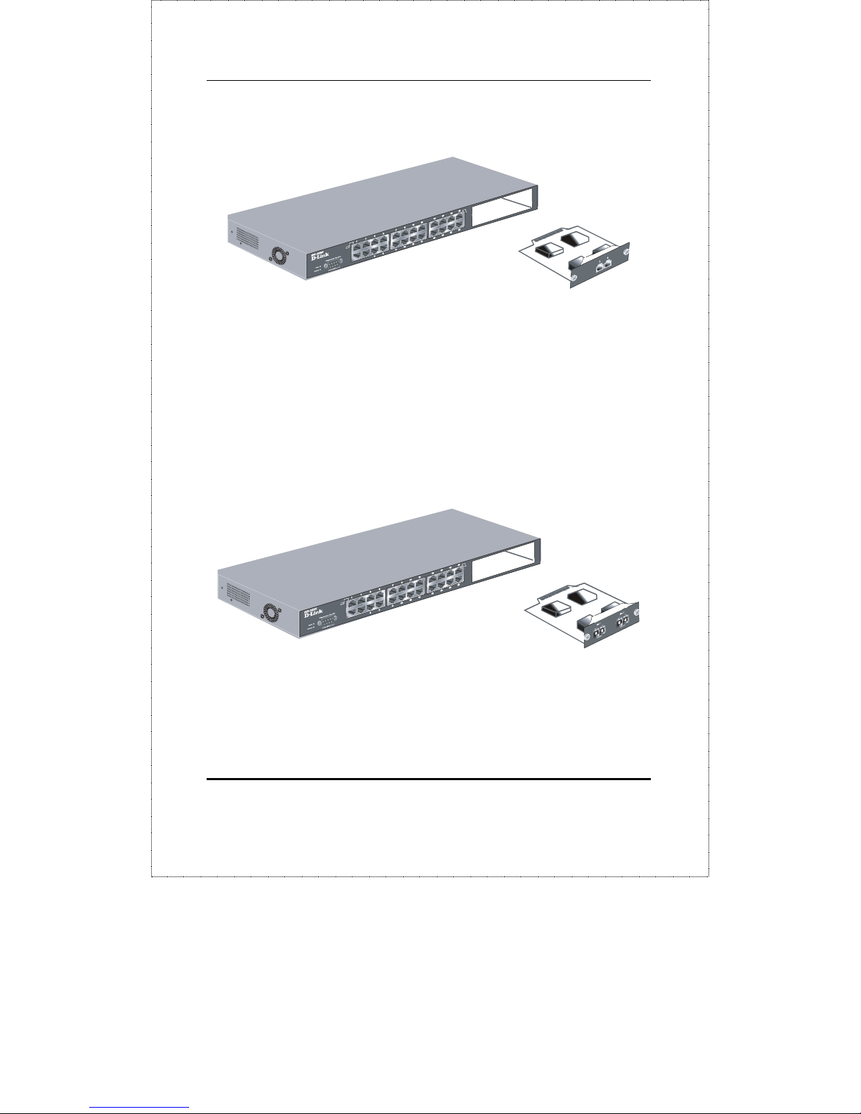
1000BASE-T Module
Figure 3-6. 1000BASE-TX two-port module
• Front-panel module.
• Connects to 1000BASE-T devices.
• Supports Category 5e UTP or STP cable connections of up
to 100 meters.
1000BASE-SX Fiber Module
Figure 3-7. 1000BASE-SX two-port module
• Front-panel module.
• Connects to 1000BASE-SX devices at full-duplex.
18
 Loading...