

D-Link DES-3228PA Web/installation Manual

©Copyright 2005. All rights reserved.
Web/Installation Guide
Product Model:
TM
DES-3228PA
Layer 2 Stackable 10/100Mbps Ethernet Switch with PoE
Release 1.0

DES-3228PA Embedded Web System User Guide
Table of Contents
Preface.................................................................................................................................... 5
DES-3228PA User Guide Overview........................... .......................................... ... ... .... ... ... ... ... .... . 6
Intended Audience.......................................................................................................................... 7
Device Description.................................................................................................................. 8
Viewing the Device.......................................................................................................................... 8
Ports Description............................................................................................................................. 9
Cable Specifications...................................................................................................................... 10
LED Definitions ............................................................................................................................. 11
Cable, Port, and Pinout Information.............. ... ... .... ... ... ... .... ... ... ... .... ... ... ... ................................... 13
Physical Dimensions..................................................................................................................... 14
Mounting Device................................................................................................................... 16
Preparing for Installation............................................................................................................... 16
Installing the Device...................................................................................................................... 18
Connecting the Device........ ... .......................................... .... ... ... ... .... ............................................ 21
Initial Configuration...............................................................................................................22
Getting Started...................................................................................................................... 37
Starting the D-Link Embedded Web Interface............................................................................... 38
Understanding the D-Link Embedded Web Interface.................................................................... 40
Using Screen and Table Options..................................................................................................43
Resetting the Device........... ... .... ... ... ... .... ... ................................................................................... 45
Logging Off from the Device ......................................................................................................... 46
Managing Device Information............................................................................................... 47
Configuring System Time.............................................................................................................. 49
Configuring Daylight Savings Time...............................................................................................50
Resetting the Device........... ... .... ... ... ... .... ... ................................................................................... 54
Configuring SNTP......................................................................................................................... 55
Defining SNTP Global Settings..................................................................................................... 57
Defining SNTP Authentication....................................................................................................... 59
Defining SNTP Servers................................................................................................................. 61
Defining SNTP Interface Settings ................................................................................................. 63
Managing Stacking ...............................................................................................................65
Understanding the Stack Topology............................................................................................... 66
Exchanging Stacking Members.................................. .......................................... ... ... .... ... ... ... ... ...68
Page 1

Switching the Stacking Master ......................................................................................................68
Configuring Ports..................................................................................................................71
Aggregating Ports.................................................................................................................75
Configuring LACP..........................................................................................................................76
LAG Membership...........................................................................................................................78
Configuring VLANs ...............................................................................................................79
Defining VLAN Properties..............................................................................................................80
Defining VLAN Membership ..........................................................................................................82
Defining the Forwarding Database .......................................................................................85
Defining Static Forwarding Database Entries................................................................................86
Defining Dynamic Forwarding Database Entries...........................................................................88
Configuring Spanning Tree................................................................................................... 91
Defining Classic Spanning Tree ....................................................................................................92
Defining STP on Interfaces............................................................................................................94
Defining Rapid Spanning Tree ......................................................................................................96
Defining Multiple Spanning Tree ...................................................................................................98
Configuring Device Security................................................................................................105
Configuring Management Security ..............................................................................................106
Configuring Network Security......................................................................................................126
Configuring IP Information.................................................................................................. 139
Configuring Multicast Forwarding .......................................................................................149
Defining IGMP Snooping.............................................................................................................150
Defining Multicast Bridging Groups .............................................................................................152
Managing Power over Ethernet Devices............................................................................. 157
Defining PoE System Information................................................................................................158
Displaying and Editing PoE System Information .........................................................................159
Managing System Files....................................................................................................... 161
Downloading System Files ..........................................................................................................162
Uploading System Files...............................................................................................................164
Activating Image Files .................................................................................................................166
Copying Files...............................................................................................................................167
Configuring the File System ........................................................................................................168
Configuring Quality of Service ............................................................................................169
Quality of Service Overview ............................. ... ... ... .... .......................................... ... ... ... ... ........169
Page 2

DES-3228PA Embedded Web System User Guide
Defining General QoS Settings...................................................................................................169
Configuring QoS Mapping........................................................................................................... 174
Configuring Basic Mode.............................................................................................................. 176
Configuring SNMP.............................................................................................................. 179
SNMP v1 and v2c ............ .......................................... ... .......................................... ... .... ............. 179
SNMP v3..................................................................................................................................... 179
Configuring SNMP Security ........................................................................................................ 180
Configuring SNMP Notifications..................................................................................................191
Managing System Logs ...................................................................................................... 199
Enabling System Logs ................................................................................................................ 200
Viewing the Device Memory Logs............................................................................................... 202
Managing Device Diagnostics.............................................................................................207
Configuring Port Mirroring........................................................................................................... 208
Viewing Integrated Cable Tests..................................................................................................210
Viewing Optical Transceivers...................................................................................................... 211
Viewing Statistics................................................................................................................ 213
Viewing Interface Statistics......................................................................................................... 213
Managing RMON Statistics.............................................. .... ... ... ... .... ... ... ... ... .... .......................... 216
Appendix A, Device Specifications & Features .... ... ... ... .... ... ... ............................................. ... . 230
Appendix B Troubleshooting .................................................................................................... 237
International Offices...................................................................................................................... 32
Page 3

Page 4

DES-3228PA Embedded Web System User Guide
Preface
The Embedded Web System (EWS) is a network management system. The D-Link Embedded Web Interface configures, monitors, and troubleshoots network devices from a remote web browser. The D-Link Embedded Web
Interface web pages are easy-to-use and easy-to-navigate. In addition, The D-Link Embedded Web Interface provides real time graphs and RMON statistics to help system administrators monitor network performance.
This preface provides an overview to the D-Link Embedded Interface User Guide, and includes the following sections:
• DES-3228PA User Guide Overview
• Intended Audience
Page 5

Preface
DES-3228PA User Guide Overview
DES-3228PA User Guide Overview
This user guide is divided into the following sections to provide concise information for installing, configuring, and
managing the device:
• Using the Installation Guide
• Using the Embedded Web Interface User Guide
Using the Installation Guide
This section provides an overview of the D-Link DES-3228PA Installation Guide, which includes the following sections:
• Section 1. Device Description — Provides a system description including the hardware components.
• Section 2. Mounting Device — Provides step-by-step instructions for installing the device.
• Section 3. Initial Configuration — Provides step-by-step instructions for the initial device configuration.
Using the Embedded Web Interface User Guide
This section provides an overview to the D-Link Web System Interface User Guide. The D-Link Web System Interface User Guide provides the following sections:
• Section 4. Getting Started — Provides information about using the EWS, including The D-Link Embedded
Web Interface interface, management, and information buttons, as well as information about adding, modifying, and deleting device information.
• Section 5. Managing Device Information —Provides information about opening the device zoom view,
defining general system information, and enabling Jumbo frames.
• Section 6. Managing Stacking — Provides information about managing stacking.
• Section 7. Configuring Ports — Provides information about configuring ports.
• Section 8. Aggregating Ports — Provides information about configuring Link Aggregated Groups and
LACP.
• Section 9. Configuring VLANs — Provides information about configuring and managing VLANs, including
information about GARP and GVRP, and defining VLAN groups.
• Section 10. Defining the Forwarding Database — Provides information about configuring and managing
both static and dynamic MAC addresses.
• Section 11. Configuring Spanning Tree — Provides information about configuring Spanning Tree Protocol
and the Rapid Spanning Tree Protocol.
• Section 12. Configuring Device Security — Provides information about configuring device security for
management security, traffic control, and network security.
• Section 13. Configuring IP Information — Provides information about defining device IP addresses, ARP,
and Domain Name Servers.
• Section 14. Configuring Multicast Forwarding — Provides information about Multica s t Forwarding.
• Section 15. Managing Power over Ethernet Devices — Provides information about managing PoE.
• Section 16. Managing System Files — Provides information about downloading, uploading, and copying
system files.
• Section 17. Configuring Quality of Service — Provides information about configuring Quality of Ser-
vice on the device.
• Section 18. Configuring SNMP — Provides information about defining SNMP v1,v2c, and v3 management,
including SNMP filters and notifications.
• Section 19. Managing System Logs — Provides information about enabling and defining system logs.
Page 6

DES-3228PA Embedded Web System User Guide
• Section 20. Managing Device Diagnostics — Provides information about configuring port mirroring, testing
copper and fiber cables, and viewing device health information.
• Section 21. Viewing Statistics — Provides information about viewing device statistics, including RMON sta-
tistics, device history events, and port and LAG utilization statistics.
• Appendix B Troubleshooting — Provides basic troubleshooting for installing the device.
• Appendix A, Device Specifications & Features — Provides device Specifications & Features
Intended Audience
This guide is intended for network administrators familiar with IT concepts and terminology.
Page 7

Device Description
Viewing the Device
Section 1. Device Description
This section contains a description of the D-Link DES-3228PA and contains the following topics:
• Viewing the Device
• Ports Description
• Cable Specifications
• LED Definitions
• Cable, Port, and Pinout Information
• Physical Dimensions
Viewing the Device
The device described in this section is a stackable Fast Ethernet Managed Switch. Device management is
performed using an Embedded Web Server (EWS) or through a Command Line Interface (CLI). The device
configuration is performed via RS-232 interface.
This section contains descriptions for the following:
• Front Panel
• Back Panel
Front Panel
DES-3228PA is a high-performance Fast Ethernet switch that provides 24-Port 10/100Mbps + 2 Combo Copper/
SFP (100BASE-FX/1000BASE-X Fiber ports) + 2 1000 Mbps Copper stacking ports.
The following figure illustrates the DES-3228PA front panel.
Figure 1: DES-3228PA Front Panel
The device front panel is configured as follows:
• 24 10/100Base-T ports — RJ-45 TX auto-sensing switching ports. The RJ-45 ports are designated as ports
Ports 1-24.
• RS-232 Console port — An asynchronous serial console port supporting the RS-232 electrical specification.
The port is used to connect the device to the console managing the device.
• 2 SFP 100BASE-FX/1000BASE-X Fiber ports — There are two T/SFP ports designated as ports Ports 25
and 26, which are also Combo ports.
Page 8
DES-3228PA Embedded Web System User Guide
• 2 Copper 100BASE-T/1000BASE-T ports — RJ-45 TX auto-sensing switching po rts designated as ports
Ports 25 and 26, which are also Combo ports.
• 2 1000Base-T stacking ports — Two RJ-45 stacking ports designated as ports Ports 27 and 28.
• LED Indicators — Port activity Light Emitting Diodes (LED) for each port and system LEDs that are dis-
played separately.
• Reset — A recessed reset button used for resetting the device.
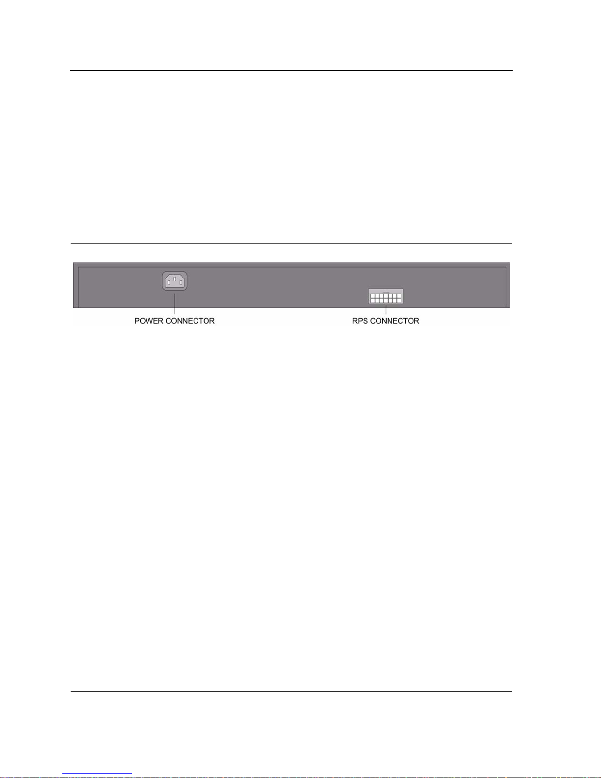
Back Panel
The following figure illustrates the DES-3228PA back panel.
Figure 2: DES-3228PA Back Panel
The DES-3228PA device back panel is configured as follows:
• RPS Connector — Redundant Power Supply (RPS) DC connector.
• Power Connector — AC power supply interface.
Ports Description
This section describes the device ports and includes the following topics:
• 10/100Base-T Fast Ethernet Ports
• Combo Copper/SFP Port (100Base-FX/1000Base-X Fiber Ports)
• 1000Base-T Stacking Ports
• RS-232 Console Port
10/100Base-T Fast Ethernet Ports
The device contains 10/100 Base-TX Fast Ethernet ports. The ports are an RJ-45 ports which support half- and
full-duplex mode 10/100Mbps.
Combo Copper/SFP Port (100Base-FX/1000Base-X Fiber Ports)
Small Form Factor Pluggable (SFP) Optical Transceivers are integrated duplex data GBIC links for bi-directional
communication over multimode optical fiber, designed for high-speed Fiber Channel data links. The SFP port is
designated as 1000Base-X.
The SFP (GBIC) port can be removed and inserted as required. The following figure illustrates the GBIC insertion.
Page 9
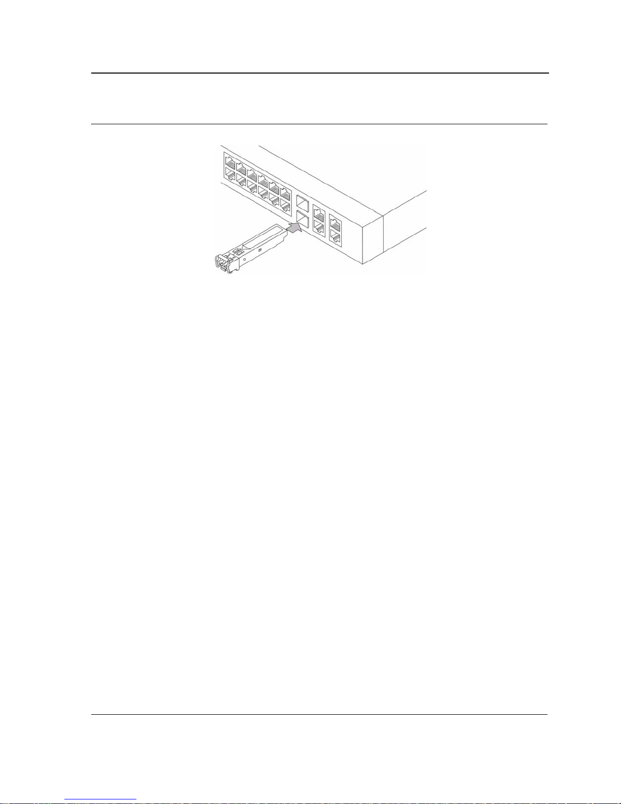
Figure 3: Inserting a GBIC into the Device
1000Base-T Stacking Ports
Copper stacking ports that support 1000Base-T standard.
Device Description
Ports Description
Stacking Ports
The device provides two stacking HyperG.Link interface ports. One stacking port provides an Up connection, while
the second provides a Down stacking connection.
RS-232 Console Port
The RS-232 port is an asynchronous serial console port supporting the RS-232 electrical specification. The port is
used to connect the device to a console managing the device. This interface configuration is as follows:
• Eight data bits.
• One stop bit.
• No parity.
• Baud rate is 9600 (default). The range is from 9600 to 115200 bps.
• Console speeds of 57600 and 115200.
Page 10
DES-3228PA Embedded Web System User Guide
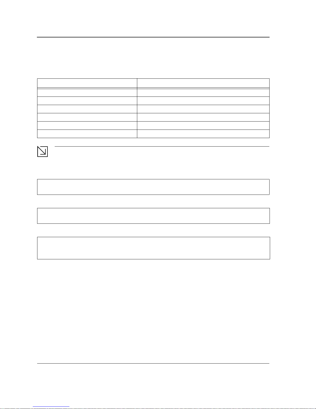
Cable Specifications
The following table contains the various cable specification for the DES-3228PA:
Table 1: DES- 3228PA Cable Specifications
Cable Type Description
10/100Base-T UTP CAT-3/4/5 (100 meters maximum)
UTP Cat. 5e (100 meters maximum)
1000Base-T
1000BASE-LX Single-mode fiber module (10km)
1000BASE-SX Multi-mode fiber module (550m)
1000BASE-LH Single-mode fiber module (40km)
1000BASE-ZX Single-mode fiber module (80km)
Mini-GBIC
UTP Cat. 5 (100 meters maximum)
EIA/TIA-568B 150-ohm STP (100 meters maximum)
SFP Transceiver for 1000BASE-LX Single-mode fiber module (10km)
SFP Transceiver for 1000BASE-SX Multi-mode fiber module (550m)
SFP Transceiver for 1000BASE-LH Single-mode fiber module (40km)
SFP Transceiver for 1000BASE-ZX Single-mode fiber module (80km)
LED Definitions
The device front panels contain Light Emitting Diodes (LED) that indicate the device status.The different LED
types are as follows:
• Port LEDs — Indicates the port status.
• System LEDs — Indicates the device status.
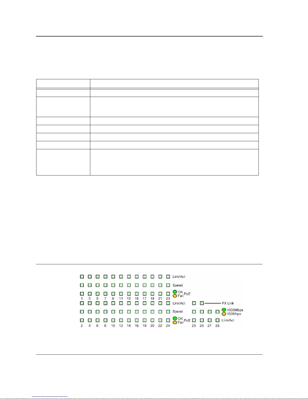
Port LEDs
10/100Base-T Fast Ethernet RJ-45 Port LEDs
The following figure illustrates the port LEDs.
Figure 4: DES-3228PA 10/100Base-T Fast Ethernet RJ-45 Port LEDs
Page 11

Device Description
LED Definitions
The RJ-45 ports have three LEDs, one for speed, one for Link /activity and one for PoE. The LED indications are
described in the following table:
Table 2: DES - 3228PA Fast Ethernet RJ-45 Port LED Indications
Port Description LED Indication Description
Speed Green Indicates the port is currently operating at 100 Mbps.
Off Indicates the port is currently operating at 10 Mbps.
Link/Activity LED Green Indicates a link is established on the port.
Flashing green Indicates that there is data transmission on the port.
Off Indicates that there is no link established on the port.
PoE Status LED Green
Amber
Off Indicates that there is no device connecting to the port.
The SFP ports have three LEDs, one for speed, one for Link /activity and one for FX link. The LED indications are
described in the following table:
Indicates that power is being provided to the device
connected to the port.
Indicates that power cannot be provided to the device
connected to the port.
Table 3: DES - 3228PA Copper Copper/SFP Port LED Indications
Port Description LED Indication Description
Link/Activity Green Indicates there is currently a link is established on the port.
Flashing green Indicates that there is data transmission on the port.
Off Indicates that there is no link established on the port.
Speed LED Green Indicates the port is currently operating at 1000 Mbps.
Off Indicates the port is currently operating at 100 Mbps.
FX Link Green
Indicates there is currently a FX link is established on the
port.
Off Indicates that there is no FX link established on the port.
The stacking GIGA ports have two LEDs, one for speed and one for Link /activity. The LED indications are
described in the following table:
Table 4: DES - 3228PA Stacking GIGA Port LED Indications
Port Description LED Indication Description
Link/Activity LED Green Indicates there is currently a link is established on the port.
Flashing Green Indicates that there is data transmission on the port.
Off Indicates that there is no link established on the port.
Speed LED Green Indicates the port is currently operating at 1000 Mbps.
Amber Indicates the port is currently operating at 100 Mbps.
Off Indicates that there is no link established on the port.
Page 12
DES-3228PA Embedded Web System User Guide
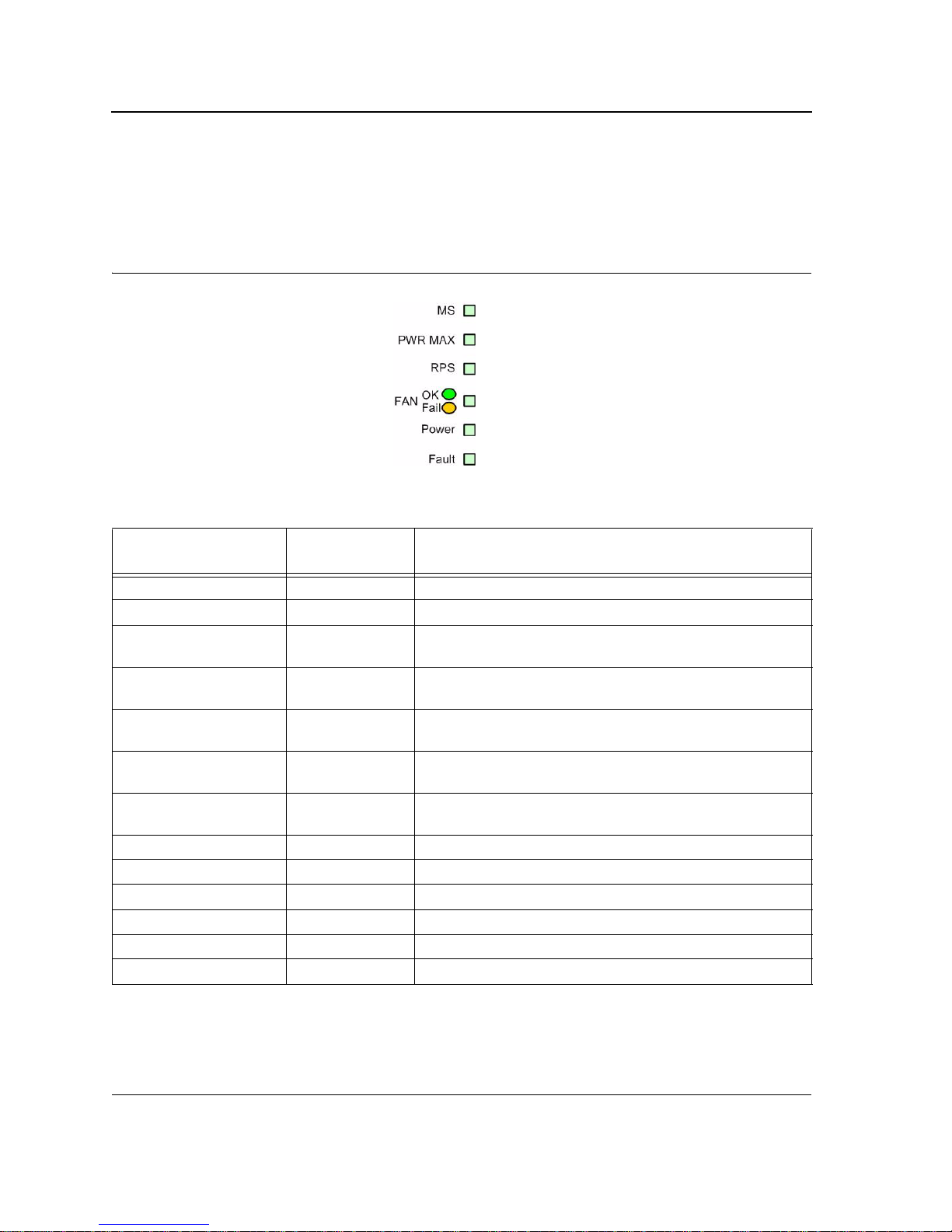
System LEDs
The DES-3228PA system LEDs located on the left side of the device. The following figure illustrates the DES3228PA system LEDs.
Figure 5: DES-3228PA System LEDs
The LED indications are described in the following table:
Table 5: System LEDs
LED Description LED
Indication
MS Red Indicates that the device is designated as the stack master.
Green Indicates that the device is designated as stack member.
Off
PWR MAX Amber
Off
RPS Green
Off
FAN Amber Indicates that there is a faulty fan.
Green Indicates that all fans are functioning correctly.
PWR Green Indicates that the device is powered up.
Off Indicates that the device is off.
Fault Red Flashing Indicates that the device is currently running POST.
Red Indicates that the device detected a POST running error.
Description
Indicates the device is not a stack member, and is currently is
stand-alone mode.
Indicates that the device is operating at the maximum power
output limit.
Indicates that the device is operating at the normal power
output limit.
Indicates that the device is being powered from a Redundant
Power Supply.
Indicates that the device is being powered from a standard
AC power supply.
Page 13
Device Description
Cable, Port, and Pinout Information
Cable, Port, and Pinout Information
This section describes the devices physical interfaces and provides information about cable connections. Stations
are connected to the device ports through the physical interface ports on the front panel. For each station, the
appropriate mode (Half/Full Duplex, Auto Negotiation) is set. The default is Auto Negotiation.
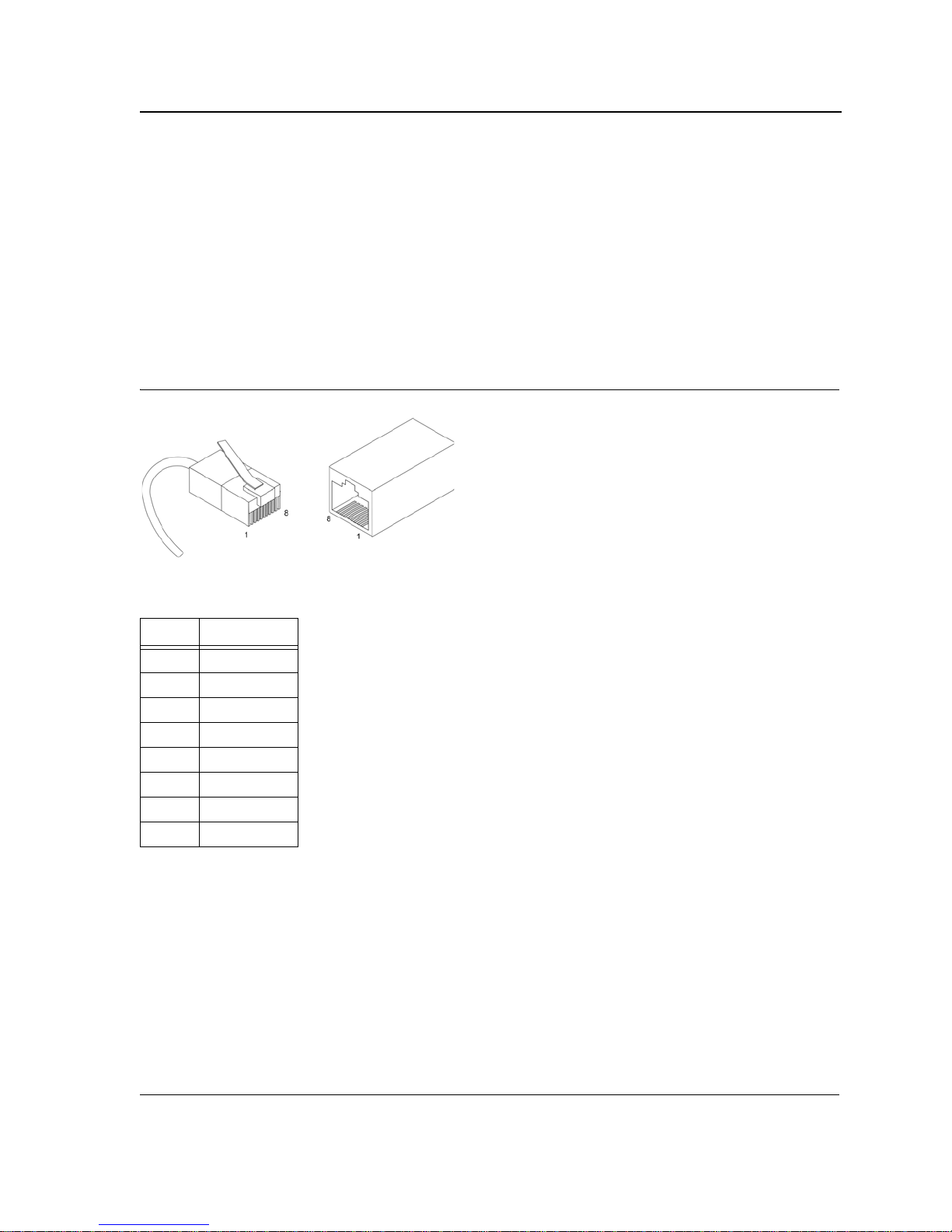
Pin Connections for the 10/100/1000 Ethernet Interface
The switching port can connect to stations wired in standard RJ-45 Ethernet station mode using straight cables.
Transmission devices connected to each other use crossed cables. The following figure illustrates the pin
allocation.
Figure 6: RJ-45 Pin Allocation
The following table describes the pin allocation
Table 6: RJ-45 Pin Connections for 10/100/1000 Base-TX
Pin Use
1 TxRx 1+
2 TxRx 13 TxRx 2+
4 TxRx 25 TxRx 3+
6 TxRx 37 TxRx 4+
8 TxRx 4-
Physical Dimensions
The device has the following physical dimensions:
• Width: 440 mm (17.32 inch)
• Depth: 310mm (12.20 inch)
• Height: 45 mm (1.77 inch)
Page 14

DES-3228PA Embedded Web System User Guide
Page 15

Mounting Device
Preparing for Installation
Section 2. Mounting Device
This section contains information for installing the device, and includes the following sections:
• Preparing for Installation
• Installing the Device
• Connecting the Device
• Rack Installation
Preparing for Installation
This section provides an explanation for preparing the installation site, and includes the following topics:
• Installation Precautions
• Site Requirements
• Unpacking
Installation Precautions
Warnings
• The surface on which the switch is placed should be adequately secured to prevent it from becoming
unstable and/or falling over.
• Ensure the power source circuits are properly grounded.
• Observe and follow service markings. Do not service any product except as explained in your system
documentation. Opening or removing covers marked with a triangular symbol with a lighting bolt may
cause electrical shock. These components are to be serviced by trained service technicians only.
• Ensure the power cable, extension cable, and/or plug is not damaged.
• Ensure the product is not exposed to water.
• Ensure the device is not exposed to radiators and/or heat sources.
• Do not push foreign objects into the device, as it may cause a fire or electric shock.
• Use the device only with approved equipment.
• Allow the product to cool before removing covers or touching internal equipment.
• Ensure the switch does not overload the power circuits, wiring, and over-current protection. To determine the possibility of overloading the supply circuits, add together the ampere ratings of all devices
installed on the same circuit as the device being installed. Compare this total with the rating limit for
the circuit. The maximum ampere ratings are usually printed on the switch, near their AC power connectors.
Cautions
• Ensure the air flow around the front, sides, and back of the switch is not restricted.
• Ensure the cooling vents are not blocked.
• Do not install the switch in an environment where the operating ambient temperature might exceed
40ºC (104ºF).
Page 16

DES-3228PA Embedded Web System User Guide
Site Requirements
Before installing the unit, verify that the location selected for installation meets the following site requirements.
• General — Ensure that the power supply is correctly installed.
• Power — Ensure that the unit is installed within 1.5 m (5 feet) of a grounded, easily accessible outlet 100-250
VAC, 50-60 Hz.
• Clearance — Ensure that there is adequate frontal clearance for operator access. Allow clearance for
cabling, power connections and ventilation.
• Cabling — Ensure that the cabling is routed to avoid sources of electrical noise such as radio transmitters,
broadcast amplifiers, power lines and fluorescent lighting fixtures.
• Ambient Requirements — Ensure that the ambient unit operating temperature range is 0 to 40ºC (32 to
104ºF) at a relative humidity of up to 95%, non-condensing. Verify that water or moisture cannot enter the
device casing.
Unpacking
This section contains information for unpacking the device, and includes the following topics:
• Package Contents
• Unpacking Essentials
Package Contents
While unpacking the device, ensure that the following items are included:
• The device
• Four rubber feet with adhesive backing
• Rack kit
• An AC power cable
• Console RS-232 cable with DB-9 connector
• Documentation CD
Unpacking Essentials
Note
Before unpacking the device, inspect the package and report any evidence of damage immediately.
To unpack the device perform the following:
1. It is recommended to put on an ESD wrist strap and attach the ESD clip to a metal surface to act as ground.
An ESD strap is not supplied with the device.
2. Place the container on a clean flat surface and cut all straps securing the container.
3. Open the container.
4. Carefully remove the device from the container and place it on a secure and clean surface.
5. Remove all the packaging material.
6. Inspect the product for damage. Report any damage immediately.
If any item is found missing or damaged, please contact your local D-Link reseller for replacement.
Page 17
Mounting Device
Installing the Device
Installing the Device
The device can be installed on a flat surface or mounted in a rack. This section includes the following topics:
• Desktop or Shelf Installation
• Rack Installation
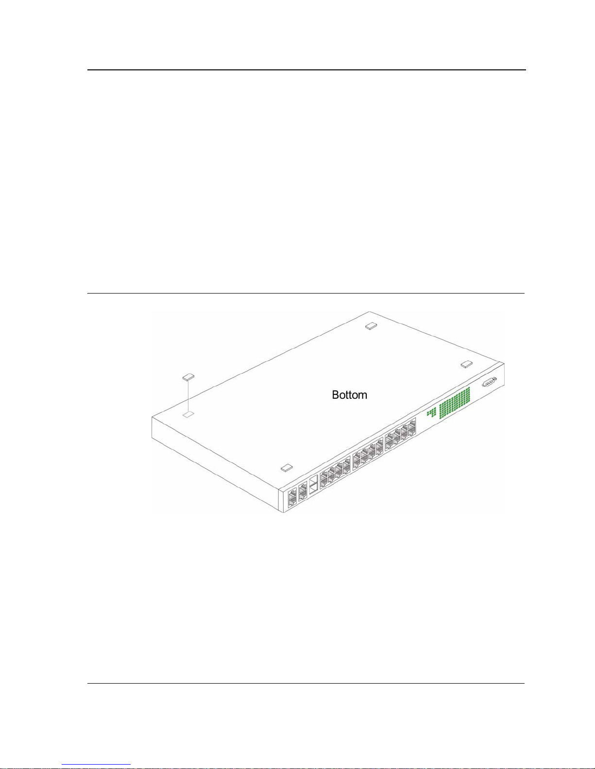
Desktop or Shelf Installation
When installing the switch on a desktop or shelf, the rubber feet included with the device should first be attached.
Attach these cushioning feet on the bottom at each corner of the device.
Ensure the surface is be able to support the weight of the device and the device cables.
To install the device on a surface, perform the following:
1. Attach the rubber feet on the bottom of the device. The following figure illustrates the rubber feet installation
on the device.
Figure 7: Installing Rubber Feet
2. Set device down on a flat surface, while leaving 2 inches on each side and 5 inches at the back.
3. Ensure that the device has proper ventilation by allowing adequate space for ventilation between the device
and the objects around the device.
Page 18
DES-3228PA Embedded Web System User Guide
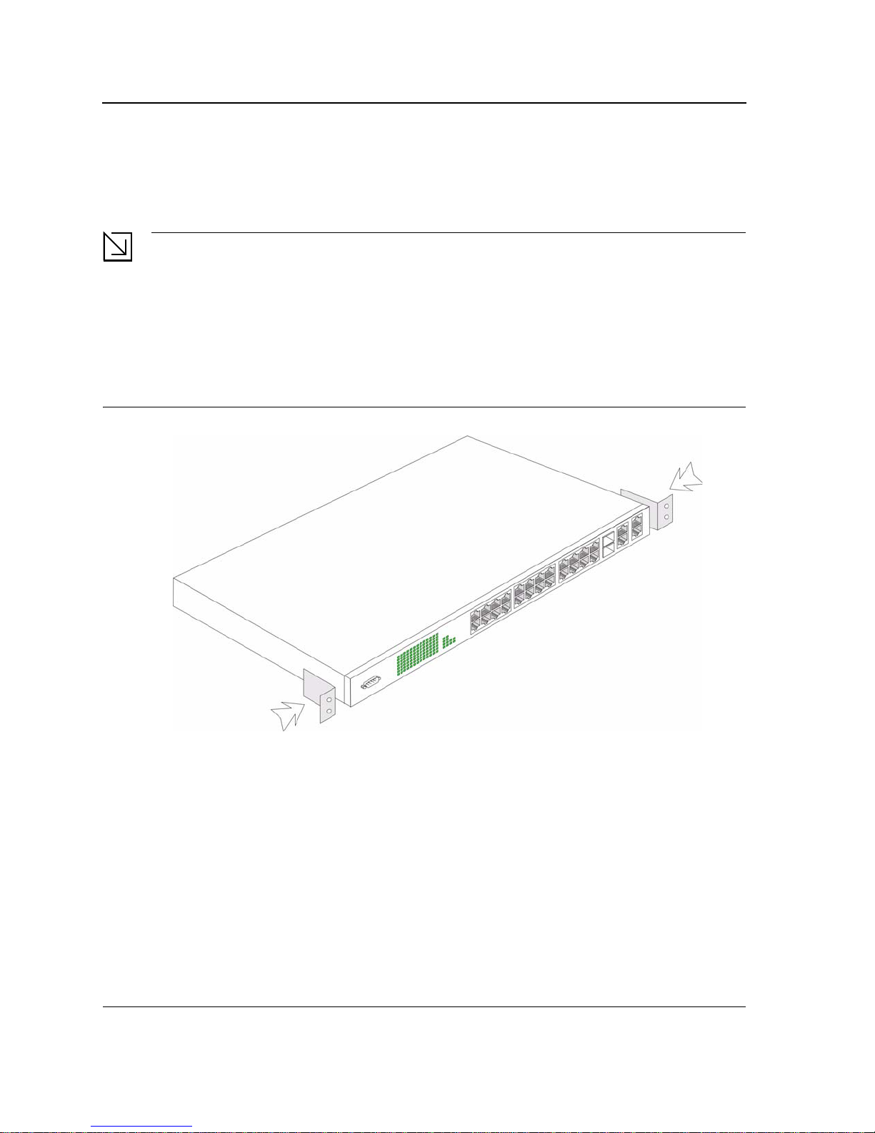
Rack Installation
The device can be mounted in an EIA standard-sized, 19-inch rack, which can be placed in a wiring closet with
other equipment. To install, the device the mounting brackets must first be attached on the devices’s sides.
Notes
• Disconnect all cables from the unit before mounting the device in a rack or cabinet.
• When mounting multiple devices into a rack, mount the devices from the bottom up.
To install the device in a rack, perform the following:
1. Place the supplied rack-mounting bracket on one side of the device ensuring the mounting holes on the
device line up to the mounting holes on the rack mounting bracket. The following figure illustrates where to
mount the brackets.
Figure 8: Attaching the Mounting Brackets
2. Insert the supplied screws into the rack mounting holes and tighten with a screwdriver.
3. Repeat the process for the rack-mounting bracket on the other side of the device.
4. Insert the unit into the 19-inch rack ensuring the rack-mounting holes on the device line up to the mounting
hole on the rack. The following figure illustrates lining up and mounting the device in the rack.
Page 19
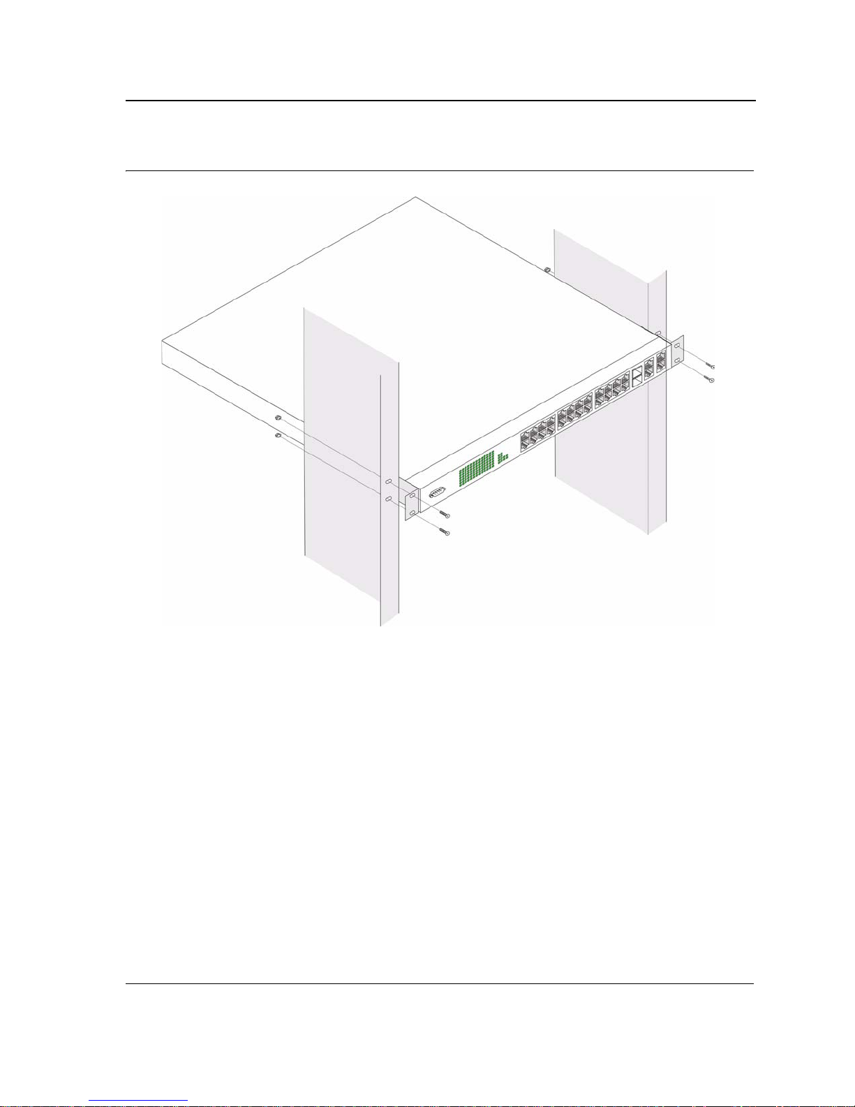
Figure 9: Mounting Device in a Rack
Mounting Device
Installing the Device
5. Secure the unit to the rack with the rack screws (not provided). Fasten the lower pair of screws before the
upper pair of screws. This ensures that the weight of the unit is evenly distributed during installation. Ensure
that the ventilation holes are not obstructed.
Page 20

DES-3228PA Embedded Web System User Guide
Connecting the Device
This section describes how to connect the d evice, and includes the following sections:
• Connecting the Switch to a Terminal
• AC Power Connection
Connecting the Switch to a Terminal
The device is connected to a terminal through an console port on the front panel, which enables a connection to a
terminal desktop system running terminal emulation software for monitoring and configuring the device.
The terminal must be a VT100 compatible terminal or a desktop or portable system with a serial port and running
VT100 terminal emulation software.
To connect a terminal to the device Console port, perform the following:
1. Connect a cable to the terminal running VT100 terminal emulation software.
2. Ensure that the terminal emulation software is set as follows:
a) Select the appropriate port to connect to the device.
b) Set the data rate to 9600 baud.
c) Set the data format to 8 data bits, 1 stop bit, and no parity.
d) Set flow control to none.
e) Under Properties, select VT100 for Emulation mode.
f) Select Terminal keys for Function, Arrow, and Ctrl keys. Ensure that the setting is for Terminal keys (not
Windows keys).
Note
When using HyperTerminal with Microsoft Windows 2000, ensure that you have Windows 2000 Service
Pack 2 or later installed. With Windows 2000 Service Pack 2, the arrow keys function properly in
HyperTerminal’s VT100 emulation. Go to www.microsoft.com for information on Windows 2000 service
packs.
3. Connect the cable to the console port on the device front panel.
AC Power Connection
To connect the power supply perform the following:
1. Using a 5-foot (1.5 m) standard power cable with safety ground connected, connect the power cable to the
AC main socket located on the back panel.
2. Connect the power cable to a grounded AC outlet.
3. Confirm that the device is connected and operating by checking that the Power Supply LED on the front panel
is green.
Page 21

Initial Configuration
Section 3. Initial Configuration
This section describes the initial device configuration and includes the following topics:
• General Configuration Information
• Booting the Switch
• Configuration Overview
• Advanced Configuration
• Software Download and Reboot
• Startup Menu Functions
After completing all external connections, connect a terminal to the device to monitor the boot and other procedures. The order of installation and configuration procedures is illustrated in the following figure. For the initial configuration, the standard device configuration is performed. Other functions can be performed, but doing so
suspends the installation process and causes a system reboot.
Performing other functions is described later in this section.
General Configuration Information
Your device has predefined features and setup configuration.
Auto-Negotiation
Auto-negotiation allows a device to advertise modes of operation and share information with anothe r device that
shares a point-to-point link segment. This automatically configures both devices to take maximum advantage of
their abilities.
Auto-negotiation is performed completely within the physical layers du ring link initiation, without any additional
overhead to either the MAC or higher protocol layers. Auto-negotiation allows the ports to do the following:
• Advertise their abilities
• Acknowledge receipt and understanding of the common modes of operation that both devices share
• Reject the use of operational modes that are not shared by both devices
• Configure each port for the highest-level operational mode that both ports can support
If connecting a port of the switch to the Network Interface Card (NIC) of a terminal that does not support autonegotiation or is not set to auto-negotiation, both the device port and the NIC must be manually set with the Web
browser interface or CLI commands to the same speed and duplex mode.
Note
If the station on the other side of the link attempts to auto-negotiate with a port that is manually configured
to full duplex, the auto-negotiation results in the station attempting to operate in half duplex. The resulting
mismatch may lead to significant frame loss. This is inherent in the auto-negotiation standard.
Page 22
DES-3228PA Embedded Web System User Guide
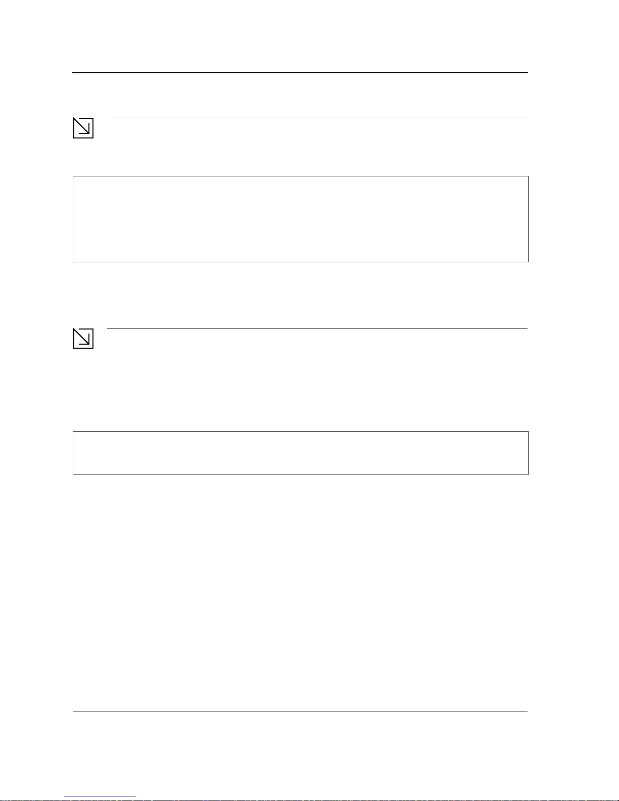
Device Port Default Settings
The following table describes the device port default settings.
Table 5: Device Port Defaults
Function Default Settings
Port speed and mode 100M Auto-negotiation
Copper/Fiber GE 1000M
Port forwarding state Enabled
Head of line blocking prevention On (Enabled)
Flow Control Off
Back Pressure Off
Note
These default settings can be modified once the device is installed.
The following is an example for changing the port speed on port g1 using CLI commands:
Console (config)#
Console (config-if)#
interface ethernet
speed
100
g1
The following is an example for enabling flow control on port g1 using CLI commands:
Console (config)#
Console (config-if)#
interface ethernet
flowcontrol
on
g1
The following is an example for enabling back pressure on port g1 using CLI commands.
Console (config)#
Console (config-if)#
Console (config-if)#
interface ethernet
speed
10
back-pressure
g1
Booting the Switch
To boot the switch, perform the following:
1. Ensure that the device console is connected to a VT100 terminal device or VT100 terminal emulator.
2. Deactivate the AC power receptacle.
3. Connect the device to the AC receptacle.
4. Activate the AC power receptacle.
When the power is turned on with the local terminal already connected, the switch goes through Power On Self
Test (POST). POST runs every time the device is initialized and checks hardware components to determine if the
device is fully operational before completely booting. If a critical problem is detected, the program flow stops. If
POST passes successfully, a valid executable image is loaded into RAM. POST messages are displayed on the
terminal and indicate test success or failure.
Page 23

Initial Configuration
As the switch boots, the bootup test first counts the device memory availability and then continues to boot. The following screen is an example of the displayed POST.
------ Performing the Power-On Self Test (POST) ------
UART Channel Loopback Test........................PASS
Testing the System SDRAM..........................PASS
Boot1 Checksum Test...............................PASS
Boot2 Checksum Test...............................PASS
Flash Image Validation Test.......................PASS
BOOT Software Version x.x.x.xx Built 07-Jan-200x 10:53:05
Processor: xxxxxx xxxxx xxxx, xx MByte SDRAM.
I-Cache 8 KB. D-Cache 8 KB. Cache Enabled.
Autoboot in 2 seconds - press RETURN or Esc. to abort and enter prom.
The boot process runs approximately 30 seconds.
The auto-boot message that appears at the end of POST (see the last lines) indicates that no problems were
encountered during boot.
During boot, the Startup menu can be accessed if necessary to run special procedures. To enter the S t artup menu,
press <Esc> or <Enter> within the first two seconds after the auto-boot message is displayed. For information on
the Startup menu, see "Startup Menu Functions."
If the system boot is not interrupted by pressing <Esc> or <Enter>, the system continues operation by decompressing and loading the code into RAM. The code starts running from RAM and the list of numbered system ports
and their states (up or down) are displayed.
Page 24

DES-3228PA Embedded Web System User Guide
Note
The following screen is an example configuration.Items such as addresses, versions, and dates may differ
for each device.
Preparing to decompress...
Decompressing SW from image-1
638000
OK
Running from RAM...
*********************************************************************
*** Running SW Ver. x.x.x.x Date 11-Jan-200x Time 15:43:13 ***
*********************************************************************
HW version is
Base Mac address is: 00:00:b0:24:11:80
Dram size is: xxM bytes
Dram first block size is: 47104K bytes
Dram first PTR is: 0x1200000
Flash size is: xM
Devices on SMI BUS:
------------------smi dev id = 16, dev type=0xd0411ab, dev revision=0x1
Device configuration:
Prestera based - Back-to-back system
Slot 1 - DB-DX240-24G HW Rev. xx.xx
Tapi Version: xx.x.x-x
Core Version: xx.x.x-x
01-Jan-200x 01:01:22 %INIT-I-InitCompleted: Initialization task is completed
Console> 01-Jan-200x 01:01:23 %LINK-I-Up: e1
01-Jan-200x 01:01:23 %LINK-W-Down: e2
01-Jan-200x 01:01:23 %LINK-I-Up: Vlan 1
01-Jan-200x 01:01:23 %LINK-W-Down: e4
.
.
.
01-Jan-200x 01:01:23 %LINK-W-Down: e46
01-Jan-200x 01:01:23 %LINK-W-Down: e47
01-Jan-200x 01:01:23 %LINK-W-Down: e48
Page 25

Initial Configuration
After the switch boots successfully, a system prompt appears (console>) and the local terminal can be used to
begin configuring the switch. However, before configuring the switch, ensure that the software version installed on
the device is the latest version. If it is not the latest version, download and install the latest version. See "Software
Download and Reboot."
Configuration Overview
Before assigning a static IP address to the device, obtain the following information from the network administrator:
• A specific IP address allocated by the network administrator for the switch to be configured
• Network mask for the network
There are two types of configuration: Initial configuration consists of configuration functions with basic security
considerations, whereas advanced configuration includes dynamic IP configurati on and more advanced security
considerations.
After making any configuration changes, the new configuration must be saved before rebooting. To save the configuration, enter the following CLI command:
Console#
copy running-config startup-config
Initial Configuration
Initial configuration, which starts after the device has booted successfully, includes static IP address and subnet
mask configuration, and setting user name and privilege level to allow remote management. If the device is to be
managed from an SNMP-based management station, SNMP community strings must also be configured. The following configurations are completed:
• Static IP Address and Subnet Mask
• Static Route Configuration
• User Name
• SNMP Community strings
Static IP Address and Subnet Mask
IP interfaces can be configured on each port of the device. After entering the configuration command, it is recommended to check if a port was configured with the IP address by entering the “show ip interface” command.
The commands to configure the device are port specific.
To manage the switch from a remote network, a static route must be configured, which is an IP address to where
packets are sent when no entries are found in the device tables. The configured IP address must belong to the
same subnet as one of the device IP interfaces.
To configure a static route, enter the command at the system prompt as shown in the following configuration
example where 101.101.101.101 is the specific management station, and 5.1.1.100 is the static route:
Console#
Console(config)#
Console(config-if)#
Console(config-if)#
Console#
configure
ip route
interface vlan
ip address
exit
192.168.2.0/24 100.1.1.33
1
100.1.1.1 255.255.255.0
Page 26
DES-3228PA Embedded Web System User Guide
Note
100.1.1.33 is the IP address of the next hop that can be used to reach the management network
192.168.2.0.
Console# show ip inte rface
Proxy ARP is disabled
IP Address I/F Type Directed
Broadcast
100.1.1.1/24 vlan 1 static disable
User Name
A user name is used to manage the device remotely, for example through SSH, Telnet, or the Web interface. To
gain complete administrative (super-user) control over the device, the highest privilege (15) must be specified.
Note
Only the administrator (super-user) with the highest privilege level (15) is allowed to manage the device
through the Web browser interface.
For more information about the privilege level, see the CLI Reference Guide.
The configured user name is entered as a login name for remote management sessions. To configure user name
and privilege level, enter the command at the system prompt as shown in the configuration example:
Console>
Console#
Console(config)#
enable
configure
username
admin
password
lee
privilege
15
SNMP Community Strings
Simple Network Management Protocol (SNMP) provides a method for managing network devices. Devices supporting SNMP run a local software (agent). The SNMP agents maintain a list of variables, used to manage the
device. The variables are defined in the Management Information Base (MIB). The MIB presents the variables
controlled by the agent. The SNMP agent defines the MIB specification format, as well as the format used to
access the information over the network.
Access rights to the SNMP agents are controlled by access strings and SNMP community strings.
The device is SNMP-compliant and contains an SNMP agent that supports a set of standard and private MIB vari-
ables. Developers of management stations require the exact structure of the MIB tree and receive the complete
private MIBs information before being able to manage the MIBs.
All parameters are manageable from any SNMP management platform, except the SNMP management station IP
address and community (community name and access rights). The SNMP management access to the switch is
disabled if no community strings exist.
Page 27

Note
The device switch is delivered with no community strings configured.
The following screen displays the default device configuration:
Initial Configuration
Console(config)#
show snmp
Community-String Community-Access IP address
---------------- ---------------- ----------
System Contact:
System Location:
The community-string, community-access, and IP address can be configured through the local terminal during the
initial configuration procedure.
The SNMP configuration options for the Community String are as follows:
• Access rights options: ro (read only), rw (read-and-write) or su (super).
• An option to configure IP address or not: If an IP address is not configured, it means that all community mem-
bers having the same community name are granted the same access rights.
Common practice is to use two community strings for the switch one (public community) with read-only access
and the other (private community) with read-write access. The public string allows authorized management stations to retrieve MIB objects, while the private string allows authori zed management stations to retrieve and modify MIB objects.
During initial configuration, it is recommended to configure the device according to the network administrator
requirements, in accordance with using an SNMP-based management station.
To configure SNMP station IP address and community string(s) perform the following:
1. At the console prompt, enter the command
2. Enter the command
configure and press <Enter>.
3. In the configuration mode, enter the SNMP configuration command with the parameters including community
name (private), community access right (read and write) and IP address, as shown in the following example:
enable. The prompt is displayed as #.
Page 28

DES-3228PA Embedded Web System User Guide
Console#
Config(config)#
Config(config)#
Console(config)#
Community-String Community-Access IP address
---------------- ---------------- ----------
private readWrite 11.1.1.2
Traps are enabled.
Authentication-failure trap is enabled.
Trap-Rec-Address Trap-Rec-Community Version
---------------- ------------------ -------
System Contact:
System Location:
This completes the initial configuration of the device from a local terminal. The configured parameters enable further device configuration from any remote location.
configure
snmp-server community private
exit
show snmp
rw 11.1.1.2
type
router
Advanced Configuration
This section provides information about dynamic allocation of IP addresses and security management based on
the Authentication, Authorization, and Accounting (AAA) mechanism, and includes the following topics:
• Configuring IP Addresses through DHCP
• Configuring IP Addresses through BOOTP
• Security Management and Password Configuration
When configuring/receiving IP addresses through DHCP and BOOTP, the configuration received from these servers includes the IP address, and may include subnet mask and default gateway.
Retrieving an IP Address From a DHCP Server
When using the DHCP protocol to retri ev e an IP addre ss, the device acts as a DHCP client. To retrieve an IP
address from a DHCP server, perform the following steps:
1. Select and connect any port to a DHCP server or to a subnet that has a DHCP server on it, in order to retrieve
the IP address.
2. Enter the following commands to use the selected port for receiving the IP address. In the following example,
the commands are based on the port type used for configuration.
Page 29
 Loading...