


SF13
DS24001 Rev. D1-3 1 of 2 SF11 - SF14
Features
·
Low Leakage
·
Low Forward Voltage Drop
·
High Current Capability
·
Super-fast Switching Speed < 35ns
·
Plastic Material: UL Flammability
Classification Rating 94V-0
Mechanical Data
·
Case: Molded Plastic
·
Terminals: Plated Axial Leads, Solderable per
MIL-STD-202 Method 208
·
Polarity: Color Band Denotes Cathode
·
Approx. Weight: 0.3 grams
·
Mounting Position: Any
Ratings at 25°C ambient temperature unless otherwise specified.
Single phase, half wave, 60Hz, resistive or inductive load.
Maximum Ratings and Electrical Characteristics
Characteristic Symbol SF11 SF12 SF13 SF14 Unit
Maximum Recurrent Peak Reverse Voltage
V
RRM
50 100 150 200 V
Maximum RMS Voltage
V
RMS
35 70 105 140 V
Maximum DC Blocking voltage
V
DC
50 100 150 200 V
Maximum Average Forward Rectified Current .375"
9.5mm Lead Length @ T
A
=55°C
I
(AV)
1.0 A
Peak Forward Surge Current 8.3 ms single half sine-wave
superimposed on rated load (JEDEC method)
I
FM
30 A
Maximum Instantaneous Forward Voltage at 1.0A DC
V
f
0.975 V
Maximum DC Reverse Current at Rated DC Blocking
Voltage
I
R
5.0 mA
Maximum DC Reverse Current at Rated
DC Blocking Voltage @ T
A
= 150°C
I
R
50
mA
Maximum Reverse Recovery Time (Note 1)
T
rr
35 ns
Typical Junction Capacitance (Note 2)
C
J
63 pF
Operating and Storage Temperature Range
T
J
,T
STG
-65 to + 175 °C
Notes: 1. Reverse Recovery Test Conditions: I
F
=0.5 A, I
R
=1.0 A, I
RR
=0.25A
2. Measured at 1.0MHz and applied reverse voltage of 4.0V.
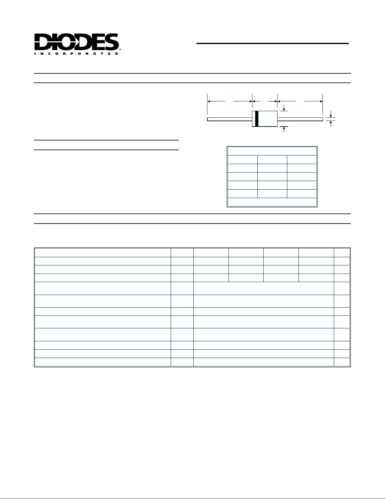
SF11 - SF14
1.0A SUPER-FAST RECOVERY RECTIFIER
A A
B
C
D
DO-41
Dim Min Max
A
25.4 —
B
4.1 5.2
C
0.71 0.86
D
2.0 2.7
All Dimensions in mm
 Loading...