


SMBJ100A
Diodes SMBJ100A, SMBJ100CA, SMBJ10A, SMBJ10CA, SMBJ110A Schematic [ru]
...
Please click here to visit our online spice models database.
Features
• 600W Peak Pulse Power Dissipation
• 5.0V - 170V Standoff Voltages
• Glass Passivated Die Construction
• Uni- and Bi-Directional Versions Available
• Excellent Clamping Capability
• Fast Response Time
• Lead Free Finish/RoHS Compliant (Note 1)
• Green Molding Compound (No Halogen and Antimony)
(Note 2)
Top View Bottom View
Green
SMBJ5.0(C)A - SMBJ170(C)A
600W SURFACE MOUNT TRANSIENT VOLTAGE SUPPRESSOR
Mechanical Data
• Case: SMB
• Case Material: Molded Plastic. UL Flammability Classification
Rating 94V-0
• Moisture Sensitivity: Level 1 per J-STD-020D
• Terminals: Lead Free Plating (Matte Tin Finish). Solderable per
MIL-STD-202, Method 208
• Polarity Indicator: Cathode Band (Note: Bi-directional devices
have no polarity indicator.)
• Marking: Information: See Page 4
• Ordering Information: See Page 4
• Weight: 0.1 grams (approximate)
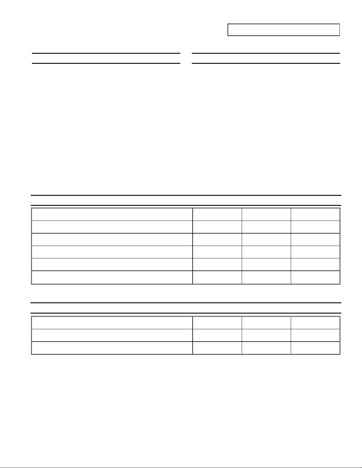
Maximum Ratings @T
Peak Pulse Power Dissipation
(Non repetitive current pulse derated above TA = 25° C) (Note 3)
Peak Power Derating Above 25°C
Peak Forward Surge Current, 8.3ms Single Half Sine Wave Superimposed
on Rated Load (Notes 3, 4, & 5)
Steady State Power Dissipation @ TL = 75°C PM
Instantaneous Forward Voltage @ IPP = 35A VBR<100V
(Notes 3, 4, & 5) V
= 25°C unless otherwise specified
A
Characteristic Symbol Value Unit
600 W
4.8
100 A
5.0 W
3.5
5.0
W/°C
V
V
BR
100V
≥
PPK
P
der
I
FSM
VF
(AV)
Thermal Characteristics
Characteristic Symbol Value Unit
Operating Temperature Range
Storage Temperature Range
Notes: 1. EU Directive 2002/95/EC (RoHS). All applicable RoHS exemptions applied. Please visit our website at http://www.diodes.com/quality/lead_free.html.
2. No purposefully added lead. Halogen and Antimony free.
3. Valid provided that terminals are kept at ambient temperature.
4. Measured with 8.3ms single half sine-wave. Duty cycle = 4 pulses per minute maximum.
5. Unidirectional units only.
TJ
T
STG
-55 to +150
-55 to +175
°C
°C
SMBJ5.0(C)A - SMBJ170(C)A
Document number: DS19002 Rev. 17 - 2
1 of 5
www.diodes.com
June 2009
© Diodes Incorporated
SMBJ5.0(C)A - SMBJ170(C)A
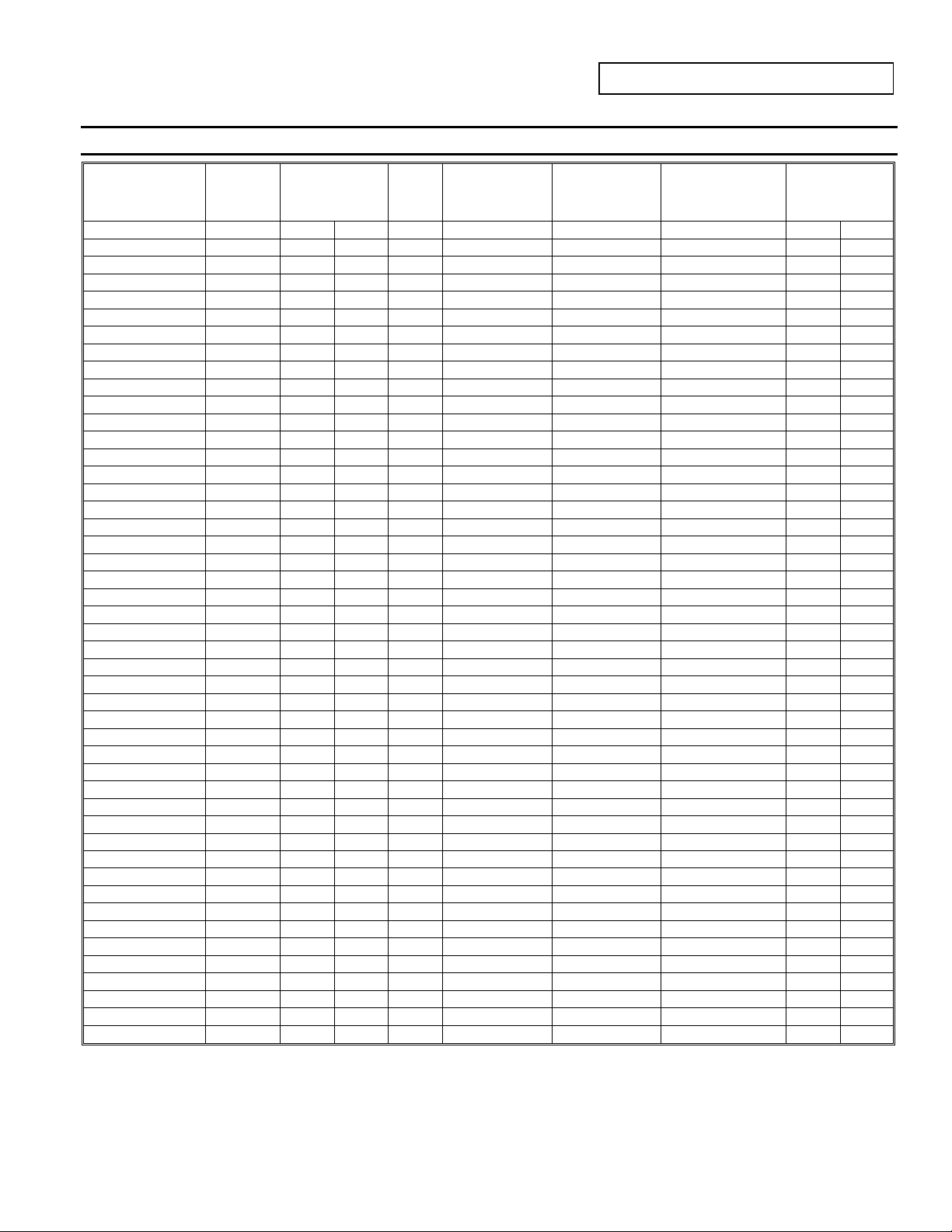
Electrical Characteristics @T
Part Number
Add C For Bi-
Directional
(Note 6)
See Note 4
Reverse
Standoff
Voltage
V
(V)
RWM
VBR @ IT (Note 7)
Min (V) Max (V)
= 25°C unless otherwise specified
A
Breakdown
Voltage
Test
Current
IT(mA) IR (μA) VC (V)
Max. Reverse
Leakage @ V
(Note 8)
Max. Clamping
RWM
Voltage @ Ipp
Max. Peak Pulse
Current
Ipp
(A) BI- UNI-
Marking Code
SMBJ5.0(C)A 5.0 6.40 7.23 10 800 9.2 65.2 AE KE
SMBJ6.0(C)A 6.0 6.67 7.67 10 800 10.3 58.3 AG KG
SMBJ6.5(C)A 6.5 7.22 8.30 10 500 11.2 53.6 AK KK
SMBJ7.0(C)A 7.0 7.78 8.95 10 200 12.0 50.0 AM KM
SMBJ7.5(C)A 7.5 8.33 9.58 1.0 100 12.9 46.5 AP KP
SMBJ8.0(C)A 8.0 8.89 10.23 1.0 50 13.6 44.1 AR KR
SMBJ8.5(C)A 8.5 9.44 10.82 1.0 10 14.4 41.7 AT KT
SMBJ9.0(C)A 9.0 10.00 11.50 1.0 5.0 15.4 39.0 AV KV
SMBJ10(C)A 10.0 11.10 12.80 1.0 5.0 17.0 35.3 AX KX
SMBJ11(C)A 11.0 12.20 14.40 1.0 5.0 18.2 33.0 AZ KZ
SMBJ12(C)A 12.0 13.30 15.30 1.0 5.0 19.9 30.2 BE LE
SMBJ13(C)A 13.0 14.40 16.50 1.0 5.0 21.5 27.9 BG LG
SMBJ14(C)A 14.0 15.60 17.90 1.0 5.0 23.2 25.8 BK LK
SMBJ15(C)A 15.0 16.70 19.20 1.0 5.0 24.4 24.0 BM LM
SMBJ16(C)A 16.0 17.80 20.50 1.0 5.0 26.0 23.1 BP LP
SMBJ17(C)A 17.0 18.90 21.70 1.0 5.0 27.6 21.7 BR LR
SMBJ18(C)A 18.0 20.00 23.30 1.0 5.0 29.2 20.5 BT LT
SMBJ20(C)A 20.0 22.20 25.50 1.0 5.0 32.4 18.5 BV LV
SMBJ22(C)A 22.0 24.40 28.00 1.0 5.0 35.5 16.9 BX LX
SMBJ24(C)A 24.0 26.70 30.70 1.0 5.0 38.9 15.4 BZ LZ
SMBJ26(C)A 26.0 28.90 33.20 1.0 5.0 42.1 14.2 CE ME
SMBJ28(C)A 28.0 31.10 35.80 1.0 5.0 45.4 13.2 CG MG
SMBJ30(C)A 30.0 33.30 38.30 1.0 5.0 48.4 12.4 CK MK
SMBJ33(C)A 33.0 36.70 42.20 1.0 5.0 53.3 11.3 CM MM
SMBJ36(C)A 36.0 40.00 46.00 1.0 5.0 58.1 10.3 CP MP
SMBJ40(C)A 40.0 44.40 51.10 1.0 5.0 64.5 9.3 CR MR
SMBJ43(C)A 43.0 47.80 54.90 1.0 5.0 69.4 8.6 CT MT
SMBJ45(C)A 45.0 50.00 57.50 1.0 5.0 72.7 8.3 CV MV
SMBJ48(C)A 48.0 53.30 61.30 1.0 5.0 77.4 7.7 CX MX
SMBJ51(C)A 51.0 56.70 65.20 1.0 5.0 82.4 7.3 CZ MZ
SMBJ54(C)A 54.0 60.00 69.00 1.0 5.0 87.1 6.9 DE NE
SMBJ58(C)A 58.0 64.40 74.60 1.0 5.0 93.6 6.4 DG NG
SMBJ60(C)A 60.0 66.70 76.70 1.0 5.0 96.8 6.2 DK NK
SMBJ64(C)A 64.0 71.10 81.80 1.0 5.0 103.0 5.8 DM NM
SMBJ70(C)A 70.0 77.80 89.50 1.0 5.0 113.0 5.3 DP NP
SMBJ75(C)A 75.0 83.30 95.80 1.0 5.0 121.0 4.9 DR NR
SMBJ78(C)A 78.0 86.70 99.70 1.0 5.0 126.0 4.7 DT NT
SMBJ85(C)A 85.0 94.40 108.20 1.0 5.0 137.0 4.4 DV NV
SMBJ90(C)A 90.0 100.0 115.50 1.0 5.0 146.0 4.1 DX NX
SMBJ100(C)A 100.0 111.0 128.00 1.0 5.0 162.0 3.7 DZ NZ
SMBJ110(C)A 110.0 122.0 140.00 1.0 5.0 177.0 3.4 EE PE
SMBJ120(C)A 120.0 133.0 153.00 1.0 5.0 193.0 3.1 EG PG
SMBJ130(C)A 130.0 144.0 165.50 1.0 5.0 209.0 2.9 EK PK
SMBJ150(C)A 150.0 167.0 192.50 1.0 5.0 243.0 2.5 EM PM
SMBJ160(C)A 160.0 178.0 205.00 1.0 5.0 259.0 2.3 EP PP
SMBJ170(C)A 170.0 189.0 217.50 1.0 5.0 275.0 2.2 ER PR
Notes: 6. Suffix C denotes Bi-directional device.
7. V
measured with IT current pulse = 300μs
BR
8. For Bi-Directional devices having V
of 10V and under, the IR is doubled.
RWM
SMBJ5.0(C)A - SMBJ170(C)A
Document number: DS19002 Rev. 17 - 2
2 of 5
www.diodes.com
© Diodes Incorporated
June 2009
 Loading...