


INTEGRATED AMPLIFIER
PMA-1500RII
OPERATING INSTRUCTIONS BEDIENUNGSANLEITUNG MODE D’EMPLOI ISTRUZIONI PER L’USO
INSTRUCCIONES DE OPERACION GEBRUIKSAANWIJZING BRUKSANVISNING
INSTRUÇÕES DE OPERAÇÃO
FOR ENGLISH READERS |
PAGE |
2 |
~ 15 |
|
|
FÜR DEUTSCHE LESER |
SEITE |
2 |
~7, 16 |
~ 24 |
|
POUR LES LECTEURS FRANCAIS |
PAGE |
2 |
~7, |
25 |
~ 33 |
PER IL LETTORE ITALIANO |
PAGINA |
2 ~7, |
34 |
~ 42 |
|
PARA LECTORES DE ESPAÑOL |
PAGINA |
2 ~7, 43 |
~ 51 |
|
VOOR NEDERLANDSTALIGE LEZERS |
PAGINA |
2 ~7, 52 |
~ 60 |
|
FÖR SVENSKA LÄSARE |
SIDE |
2 ~7, |
61 |
~ 69 |
PARA LEITORES PORTUGUESES |
PÁGlNA |
2 ~7, |
70 |
~ 78 |

ENGLISH DEUTSCH FRANCAIS ITALIANO ESPAÑOL NEDERLANDS SEVENSKA PORTUGUÊS
■ SAFETY PRECAUTIONS
WARNING:
TO PREVENT FIRE OR SHOCK HAZARD, DO NOT EXPOSE THIS APPLIANCE TO RAIN OR MOISTURE.
“SERIAL NO.
PLEASE RECORD UNIT SERIAL NUMBER ATTACHED TO THE REAR OF THE CABINET FOR FUTURE REFERENCE”
CAUTION:
•The ventilation should not be impeded by covering the ventilation openings with items, such as newspapers, table-cloths, curtains, etc.
•No naked flame sources, such as lighted candles, should be placed on the apparatus.
•Please be care the environmental aspects of battery disposal.
•The apparatus shall not be exposed to dripping or splashing for use.
•No objects filled with liquids, such as vases, shall be placed on the apparatus.
CAUTION:
TO REDUCE THE RISK OF ELECTRIC SHOCK, DO NOT REMOVE COVER (OR BACK). NO USER-SERVICEABLE PARTS INSIDE. REFER SERVICING TO QUALIFIED SERVICE PERSONNEL.
The lightning flash with arrowhead symbol, within an equilateral triangle, is intended to alert the user to the presence of uninsulated “dangerous voltage” within the product’s enclosure that may be of sufficient magnitude to constitute a risk of electric shock to persons.
The exclamation point within an equilateral triangle is intended to alert the user to the presence of important operating and maintenance (servicing) instructions in the literature accompanying the appliance.
• |
DECLARATION OF CONFORMITY |
• |
DECLARACIÓN DE CONFORMIDAD |
|
We declare under our sole responsibility that this product, to |
|
Declaramos bajo nuestra exclusiva responsabilidad que este |
|
which this declaration relates, is in conformity with the following |
|
producto al que hace referencia esta declaración, está con- |
|
standards: |
|
forme con los siguientes estándares: |
|
EN60065, EN55013, EN55020, EN61000-3-2 and EN61000-3- |
|
EN60065, EN55013, EN55020, EN61000-3-2 y EN61000-3-3. |
|
3. |
|
Siguiendo las provisiones de las Directivas 73/23/EEC, 89/336/ |
|
Following the provisions of 73/23/EEC, 89/336/EEC and 93/68/ |
|
EEC y 93/68/EEC. |
|
EEC Directive. |
|
|
• |
ÜBEREINSTIMMUNGSERKLÄRUNG |
• |
EENVORMIGHEIDSVERKLARING |
|
Wir erklären unter unserer Verantwortung, daß dieses Produkt, |
|
Wij verklaren uitsluitend op onze verantwoordelijkheid dat dit |
|
auf das sich diese Erklärung bezieht, den folgenden Standards |
|
produkt, waarop deze verklaring betrekking heeft, in overeen- |
|
entspricht: |
|
stemming is met de volgende normen: |
|
EN60065, EN55013, EN55020, EN61000-3-2 und EN61000-3- |
|
EN60065, EN55013, EN55020, EN61000-3-2 en EN61000-3-3. |
|
3. |
|
Volgens de bepalingen van de Richtlijnen 73/23/EEC, 89/336/ |
|
Entspricht den Verordnungen der Direktive 73/23/EEC, 89/336/ |
|
EEC en 93/68/EEC. |
|
EEC und 93/68/EEC. |
|
|
• |
DECLARATION DE CONFORMITE |
• |
ÖVERENSSTÄMMELSESINTYG |
|
Nous déclarons sous notre seule responsabilité que l’appareil, |
|
Härmed intygas helt på eget ansvar att denna produkt, vilken |
|
auquel se réfère cette déclaration, est conforme aux standards |
|
detta intyg avser, uppfyller följande standarder: |
|
suivants: |
|
EN60065, EN55013, EN55020, EN61000-3-2 och EN61000-3- |
|
EN60065, EN55013, EN55020, EN61000-3-2 et EN61000-3-3. |
|
|
|
|
3. |
|
|
D’après les dispositions de la Directive 73/23/EEC, 89/336/EEC |
|
Enligt stadgarna i direktiv 73/23/EEC, 89/336/EEC och 93/68/ |
|
et 93/68/EEC. |
|
EEC. |
• |
DICHIARAZIONE DI CONFORMITÀ |
• |
DECLARAÇÃO DE CONFORMIDADE |
|
Dichiariamo con piena responsabilità che questo prodotto, al |
|
Declaramos sob nossa exclusiva responsabilidade que este |
|
quale la nostra dichiarazione si riferisce, è conforme alle seg- |
|
produto, ao qual esta declaração corresponde, está em confor- |
|
uenti normative: |
|
midade com as seguintes normas: |
|
EN60065, EN55013, EN55020, EN61000-3-2 e EN61000-3-3. |
|
EN60065, EN55013, EN55020, EN61000-3-2 e EN61000-3-3. |
|
In conformità con le condizioni delle direttive 73/23/EEC, 89/ |
|
De acordo com o estabelecido nas Directivas 73/23/EEC, 89/ |
|
336/EEC e 93/68/EEC. |
|
336/EEC e 93/68/EEC. |
|
|
|
|
2
PORTUGUÊS SEVENSKA NEDERLANDS ESPAÑOL ITALIANO FRANCAIS DEUTSCH ENGLISH
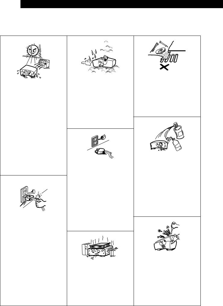
NOTE ON USE / HINWEISE ZUM GEBRAUCH / OBSERVATIONS RELATIVES A L’UTILISATION / NOTE SULL’USO / NOTAS SOBRE EL USO / ALVORENS TE GEBRUIKEN / OBSERVERA / OBSERVAÇÕES QUANTO AO USO
•Avoid high temperatures.
Allow for sufficient heat dispersion when installed on a rack.
•Vermeiden Sie hohe Temperaturen.
Beachten Sie, daß eine ausreichend Luftzirkulation gewährleistet wird, wenn das Gerät auf ein Regal gestellt wird.
•Eviter des températures élevées
Tenir compte d’une dispersion de chaleur suffisante lors de l’installation sur une étagère.
•Evitate di esporre l’unità a temperature alte. Assicuratevi che ci sia un’adeguata dispersione del calore quando installate l’unità in un mobile per componenti audio.
•Evite altas temperaturas.
Permite la suficiente dispersión del calor cuando está instalado en la consola.
•Vermijd hoge temperaturen.
Zorg voor een degelijk hitteafvoer indien het apparaat op een rek wordt geplaatst.
•Undvik höga temperaturer.
Se till att det finns möjlighet till god värmeavledning vid montering i ett rack.
•Evite temperaturas altas.
Conceda suficiente dispersão de calor quando o equipamento for instalado numa prateleira.
•Handle the power cord carefully.
Hold the plug when unplugging the cord.
•Gehen Sie vorsichtig mit dem Netzkabel um. Halten Sie das Kabel am Stecker, wenn Sie den Stecker herausziehen.
•Manipuler le cordon d’alimentation avec précaution.
Tenir la prise lors du débranchement du cordon.
•Manneggiate il filo di alimentazione con cura. Agite per la spina quando scollegate il cavo dalla presa.
•Maneje el cordón de energía con cuidado. Sostenga el enchufe cuando desconecte el cordón de energía.
•Hanteer het netsnoer voorzichtig.
Houd het snoer bij de stekker vast wanneer deze moet worden aanof losgekoppeld.
•Hantera nätkabeln varsamt.
Håll i kabeln när den kopplas från el-uttaget.
•Manuseie com cuidado o fio condutor de energia.
Segure a tomada ao desconectar o fio.
•Keep the set free from moisture, water, and dust.
•Halten Sie das Gerät von Feuchtigkeit, Wasser und Staub fern.
•Protéger l’appareil contre l’humidité, l’eau et la poussière.
•Tenete l’unità lontana dall’umidità, dall’acqua e dalla polvere.
•Mantenga el equipo libre de humedad, agua y polvo.
•Laat geen vochtigheid, water of stof in het apparaat binnendringen.
•Utsätt inte apparaten för fukt, vatten och damm.
•Mantenha o aparelho livre de qualquer umidade, água ou poeira.
•Unplug the power cord when not using the set for long periods of time.
•Wenn das Gerät eine längere Zeit nicht verwendet werden soll, trennen Sie das Netzkabel vom Netzstecker.
•Débrancher le cordon d’alimentation lorsque l’appareil n’est pas utilisé pendant de longues périodes.
•Disinnestate il filo di alimentazione quando avete l’intenzione di non usare il filo di alimentazione per un lungo periodo di tempo.
•Desconecte el cordón de energía cuando no utilice el equipo por mucho tiempo.
•Neem altijd het netsnoer uit het stopkontakt wanneer het apparaat gedurende een lange periode niet wordt gebruikt.
•Koppla ur nätkabeln om apparaten inte kommer att användas i lång tid.
•Desligue o fio condutor de força quando o aparelho não tiver que ser usado por um longo período.
*(For sets with ventilation holes)
•Do not obstruct the ventilation holes.
•Die Belüftungsöffnungen dürfen nicht verdeckt werden.
•Ne pas obstruer les trous d’aération.
•Non coprite i fori di ventilazione.
•No obstruya los orificios de ventilación.
•De ventilatieopeningen mogen niet worden beblokkeerd.
•Täpp inte till ventilationsöppningarna.
•Não obstrua os orifícios de ventilação.
•Do not let foreign objects in the set.
•Keine fremden Gegenstände in das Gerät kommen lassen.
•Ne pas laisser des objets étrangers dans l’appareil.
•E’ importante che nessun oggetto è inserito all’interno dell’unità.
•No deje objetos extraños dentro del equipo.
•Laat geen vreemde voorwerpen in dit apparaat vallen.
•Se till att främmande föremål inte tränger in i apparaten.
•Não deixe objetos estranhos no aparelho.
•Do not let insecticides, benzene, and thinner come in contact with the set.
•Lassen Sie das Gerät nicht mit Insektiziden, Benzin oder Verdünnungsmitteln in Berührung kommen.
•Ne pas mettre en contact des insecticides, du benzène et un diluant avec l’appareil.
•Assicuratevvi che l’unità non venga in contatto con insetticidi, benzolo o solventi.
•No permita el contacto de insecticidas, gasolina y diluyentes con el equipo.
•Laat geen insektenverdelgende middelen, benzine of verfverdunner met dit apparaat in kontakt komen.
•Se till att inte insektsmedel på spraybruk, bensen och thinner kommer i kontakt med apparatens hölje.
•Não permita que inseticidas, benzina e dissolvente entrem em contacto com o aparelho.
•Never disassemble or modify the set in any way.
•Versuchen Sie niemals das Gerät auseinander zu nehmen oder auf jegliche Art zu verändern.
•Ne jamais démonter ou modifier l’appareil d’une manière ou d’une autre.
•Non smontate mai, nè modificate l’unità in nessun modo.
•Nunca desarme o modifique el equipo de ninguna manera.
•Nooit dit apparaat demonteren of op andere wijze modifiëren.
•Ta inte isär apparaten och försök inte bygga om den.
•Nunca desmonte ou modifique o aparelho de alguma forma.
3

ENGLISH DEUTSCH FRANCAIS ITALIANO ESPAÑOL NEDERLANDS SEVENSKA PORTUGUÊS
NOTE:
1.Always keep the POWER switch on the main unit turned on.
2.Turn the power on and off from the remote control unit.
3.Unplug the power supply cord when you do not plan to use the unit for a long period of time.
CAUTION:
Only when the power LED is lit red, this means that the power is turned off with remote control unit. Turn the power on from the remote control unit.
HINWEIS:
1.Lassen Sie den Netzschalter (POWER) am Hauptgerät stets eingeschaltet.
2.Schalten Sie den Strom mit dem Fernbedienungsgerät ein-und aus.
3.Trennen Sie das Netzkabel vom Netz ab, wenn Sie beabsichtigen, das Gerät über einen längeren Zeitraum hinweg nicht zu benutzen.
VORSICHT:
Nur wenn die Netz-LED rot leuchtet, bedeutet, dies, dass die Stromversorgung unter Verwendung der Fernbedienung ausgeschaltet wurde. Schalten Sie den Strom vom Fernbedienungsgerät aus ein.
REMARQUE:
1.S’assurer que le commutateur d’alimentation (POWER) sur l’unité principale soit toujours dans la position activée.
2.Allumer et éteigner l’appareil avec la télécommande.
3.Débrancher le cordon d’alimentation lorsque l’appareil ne sera pas utilisé pendant une longue période.
ATTENTION:
NOTA:
1.Mantenga siempre activado el interruptor de alimentación (POWER) en la unidad principal.
2.Encienda y apague el equipo desde la unidad de control remoto.
3.Cuando la unidad vaya a estar fuera de uso por un período prolongado de tiempo, desconecte el cable de alimentación.
PRECAUCION:
El LED de alimentación solamente se enciende de color rojo, cuando la alimentación ha sido desactivada utilizando el mando a distancia. Conecte la alimentación desde la unidad de control remote.
OPMERKING:
1.Zorg er altijd voor dat de stroomschakelaar (POWER) van het hoofdtoestel in de ingeschakelde stand staat.
2.Schakel de stroom in en uit m.b.v. de afstandsbediening.
3.Trek het netsnoer uit wanneer u denkt het toestel gedurende een lange periode niet te gebruiken.
WAARSCHUWING:
Alleen wanneer het spanningslampje rood oplicht, betekent, dit dat de spanning is uitgeschakeld met de afstandsbediening. Schakel de spanning in met de afstandsbediening.
OBSERVERA:
1.Låt alltid strömbrytaren (POWER) på huvudenheten vara påslagen.
2.Slå till/från strömmen med hjälp av fjärrkontrollen.
3.Koppla loss nätkabeln om apparaten inte skall användas under lång tid.
VARNING:
Lorsque seule la LED d’alimentation est allumée en rouge, cela signifie que I’alimentation est coupée avec la télécommande. Allumer I’appareil avec la télécommande.
NOTA:
1.Tenete sempre l’interruttore della corrente (POWER) dell’unità principale nella posizione di attivazione.
2.Accendete e spegnete la corrente usando il telecomando.
3.Scollegate il filo di alimentazione quando avete intenzione di non usare l’apparecchio per un lungo periodo.
AVVERTIMENTO:
Endast när strömindikatorn lyser rött, vilket betyder att strömmen stängts av med fjärrkontrollen. Strömmen nåste då slås på via fjärrkontrollen igen.
NOTA:
1.Mantenha o interruptor da Corrente (POWER) na unidade principal sempre ligado.
2.Ligue e desligue a corrente a partir da unidade de controlo remoto.
3.Desconecte o fio de força quando intentar não utilizar a unidade por longo tempo.
CAUTELA:
Solo quando il LED d’alimentazione è rosso, significa che I’alimentazione è stata disattivata con il telecomando. Riaccendete la corrente usando il telecomando.
Apenas quando o LED estiver aceso em vermelho, isto significa que a alimentação está desligada pelo controlo remoto. Ligue a força a partir do controle remoto.
4
PORTUGUÊS SEVENSKA NEDERLANDS ESPAÑOL ITALIANO FRANCAIS DEUTSCH ENGLISH
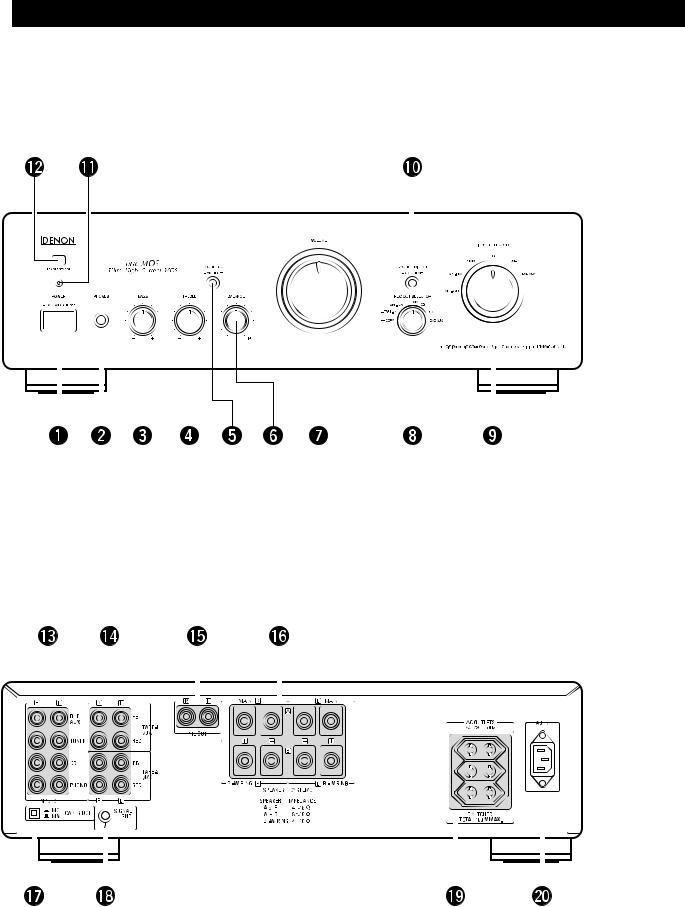
FRONT PANEL |
|
|
|
|
|
|
PANEL FRONTAL |
|||||||||||||||
FRONTPLATTE |
|
|
|
|
|
|
VOORPANEEL |
|||||||||||||||
PANNEAU AVANT |
|
|
|
|
|
|
FRAMSIDA |
|||||||||||||||
PANNELLO ANTERIORE |
|
|
|
|
|
|
PAINEL FRONTAL |
|||||||||||||||
|
|
|
|
|
|
|
|
|
|
|
|
|
|
|
|
|
|
|
|
|
|
|
|
|
|
|
|
|
|
|
|
|
|
|
|
|
|
|
|
|
|
|
|
|
|
|
|
|
|
|
|
|
|
|
|
|
|
|
|
|
|
|
|
|
|
|
|
|
|
|
|
|
|
|
|
|
|
|
|
|
|
|
|
|
|
|
|
|
|
|
|
|
|
|
|
|
|
|
|
|
|
|
|
|
|
|
|
|
|
|
|
|
|
|
|
|
|
|
|
|
|
|
|
|
|
|
|
|
|
|
|
|
|
|
|
|
|
|
|
|
|
|
|
|
|
|
|
|
|
|
|
|
|
|
|
|
|
|
|
|
|
|
|
|
|
|
|
|
|
|
|
|
|
|
|
|
|
|
|
|
|
|
|
|
|
|
|
|
|
|
|
|
|
|
|
|
|
|
|
|
|
|
|
|
|
|
|
|
|
|
|
|
|
|
|
|
|
|
|
|
|
|
|
|
|
|
|
|
|
|
|
|
|
|
|
|
|
|
|
|
|
|
|
|
|
|
|
|
|
|
|
|
|
|
|
|
|
|
|
|
|
|
|
|
|
|
|
|
|
|
|
|
|
|
|
|
|
|
|
|
|
|
|
|
|
|
|
|
|
|
|
|
|
|
|
|
|
|
REAR PANEL |
|
|
PANEL TRASERO |
|
|
|
|||||||||||||||||||||||||||||||||||||||||
RÜCKWAND |
|
|
ACHTERPANEEL |
|
|
|
|||||||||||||||||||||||||||||||||||||||||
PANNEAU ARRIERE |
|
|
BAKSIDA |
|
|
|
|||||||||||||||||||||||||||||||||||||||||
PANNELLO POSTERIORE |
|
|
PAINEL TRAZEIRO |
|
|
|
|||||||||||||||||||||||||||||||||||||||||
|
|
|
|
|
|
|
|
|
|
|
|
|
|
|
|
|
|
|
|
|
|
|
|
|
|
|
|
|
|
|
|
|
|
|
|
|
|
|
|
|
|
|
|
|
|
|
|
|
|
|
|
|
|
|
|
|
|
|
|
|
|
|
|
|
|
|
|
|
|
|
|
|
|
|
|
|
|
|
|
|
|
|
|
|
|
|
|
|
|
|
|
|
|
|
|
|
|
|
|
|
|
|
|
|
|
|
|
|
|
|
|
|
|
|
|
|
|
|
|
|
|
|
|
|
|
|
|
|
|
|
|
|
|
|
|
|
|
|
|
|
|
|
|
|
|
|
|
|
|
|
|
|
|
|
|
|
|
|
|
|
|
|
|
|
|
|
|
|
|
|
|
|
|
|
|
|
|
|
|
|
|
|
|
|
|
|
|
|
|
|
|
|
|
|
|
|
|
|
|
|
|
|
|
|
|
|
|
|
|
|
|
|
|
|
|
|
|
|
|
|
|
|
|
|
|
|
|
|
|
|
|
|
|
|
|
|
|
|
|
|
|
|
|
|
|
|
|
|
|
|
|
|
|
|
|
|
|
|
|
|
|
|
|
|
|
|
|
|
|
|
|
|
|
|
|
|
|
|
|
|
|
|
|
|
|
|
|
|
|
|
|
|
|
|
|
|
|
|
|
|
|
|
|
|
|
|
|
|
|
|
|
|
|
|
|
|
|
|
|
|
|
|
|
|
|
|
|
|
|
|
|
|
|
|
|
|
|
|
|
|
|
|
|
|
|
|
|
|
|
|
|
|
|
|
|
|
|
|
|
|
|
|
|
|
|
|
|
|
|
|
|
|
|
|
|
|
|
|
|
|
|
|
|
|
|
|
|
|
|
|
|
|
|
|
|
|
|
|
|
|
|
|
|
|
|
|
|
|
|
|
|
|
|
|
|
|
|
|
|
|
|
|
|
|
|
|
|
|
|
|
|
|
|
|
|
|
|
|
|
|
|
|
|
|
|
|
|
|
|
|
|
|
|
|
|
|
|
|
|
|
|
|
|
|
|
|
|
|
|
|
|
|
|
|
|
|
|
|
|
|
|
|
|
|
|
|
|
|
|
|
|
|
|
|
|
|
|
|
|
|
|
|
|
|
|
|
|
|
|
|
|
|
|
|
|
|
|
|
|
|
|
|
|
|
|
|
|
|
|
|
|
|
|
|
|
|
|
|
|
|
|
|
|
|
|
|
|
|
|
|
|
|
|
|
|
|
|
|
|
|
|
|
|
|
|
|
|
|
|
|
|
|
|
|
|
|
|
|
|
|
|
|
|
|
|
|
|
|
|
|
|
|
|
|
|
|
|
|
|
|
|
|
|
|
|
|
|
|
|
|
|
|
|
|
|
|
|
|
|
|
|
|
|
|
|
|
|
|
|
|
|
|
|
|
|
|
|
|
|
|
|
|
|
|
|
|
|
|
|
|
|
|
|
|
|
|
|
|
|
|
|
|
|
|
|
|
|
|
|
|
|
|
|
|
|
|
|
|
|
|
|
|
|
|
|
|
|
|
|
|
|
|
|
|
|
|
|
|
|
|
|
|
|
|
|
|
|
|
|
|
|
|
|
|
|
|
|
|
|
|
|
|
|
|
|
|
|
|
|
|
|
|
|
|
|
|
|
|
|
|
|
|
|
|
|
|
|
|
|
|
|
|
|
|
|
|
|
|
|
|
|
|
|
|
|
|
|
5

ENGLISH DEUTSCH FRANCAIS ITALIANO ESPAÑOL NEDERLANDS SEVENSKA PORTUGUÊS
|
— TABLE OF CONTENTS — |
|
1 |
DESIGNATIONS AND FUNCTIONS OF |
|
|
PANEL CONTROLS. . . . . . . . . . . . . . . . . . . . . . . |
7, 8, 9 |
2 |
CONNECTIONS. . . . . . . . . . . . . . . . . . . . . . . . . . |
. 9, 10 |
3 |
OPERATION . . . . . . . . . . . . . . . . . . . . . . . . . . . . . |
. . .11 |
4 |
REMOTE CONTROL OPERATION . . . . . . . . . . . |
12, 13 |
5 |
TROUBLESHOOTING . . . . . . . . . . . . . . . . . . . . . . |
. . 14 |
6 |
SPECIFICATIONS . . . . . . . . . . . . . . . . . . . . . . . . . |
. . 15 |
Please check to make sure the following items are included with the main unit in the carton:
(1) Operating Instructions. . . . . . . . . . . . . . . . . . . . . . . . . . . . . . . .1
(2) Remote Control Unit (RC-885) . . . . . . . . . . . . . . . . . . . . . . . . .1
(3) Batteries R6P (AA) . . . . . . . . . . . . . . . . . . . . . . . . . . . . . . . . . .2
(4) Power Supply Cord . . . . . . . . . . . . . . . . . . . . . . . . . . . . . . . . . .1
(5) Service Station List . . . . . . . . . . . . . . . . . . . . . . . . . . . . . . . . . .1
— INHALT —
1 BEZEICHNUNGEN UND FUNKTIONEN DER BEDIENUNGSELEMENTE . . . . . . . . . . . . . . . . . 16, 17
2 ANSCHLÜSSE . . . . . . . . . . . . . . . . . . . . . . . . . . . 18, 19 3 BETRIEB . . . . . . . . . . . . . . . . . . . . . . . . . . . . . . . . . . 20 4 FERNBEDIENUNG . . . . . . . . . . . . . . . . . . . . . . . 21, 22 5 FEHLERSUCHE. . . . . . . . . . . . . . . . . . . . . . . . . . . . . 23 6 TECHNISCHE DATEN . . . . . . . . . . . . . . . . . . . . . . . . 24
Bitte überprüfen Sie, ob die folgenden Teile vollständig in der Verpackung enthalten sind:
(1) Bedienungsanleitung . . . . . . . . . . . . . . . . . . . . . . . . . . . . . . . .1
(2) Fernbedienung (RC-885) . . . . . . . . . . . . . . . . . . . . . . . . . . . . .1
(3) Batterien vom Typ R6P (AA). . . . . . . . . . . . . . . . . . . . . . . . . . .2
(4) Netzkabel . . . . . . . . . . . . . . . . . . . . . . . . . . . . . . . . . . . . . . . . .1
(5) Servicestation-Liste. . . . . . . . . . . . . . . . . . . . . . . . . . . . . . . . . .1
|
— TABLE DES MATIERES — |
|
1 |
NOMENCLATURE ET FONCTIONS DES |
|
|
COMMANDES DE PANNEAU . . . . . . . . . . . . . . . |
25, 26 |
2 |
CONNEXIONS . . . . . . . . . . . . . . . . . . . . . . . . . . . |
27, 28 |
3 |
FONCTIONNEMENT . . . . . . . . . . . . . . . . . . . . . . |
. . . 29 |
4 |
UTILISATION DE LA TELECOMMANDE. . . . . . . |
30, 31 |
5 |
DEPISTAGE DES PANNES . . . . . . . . . . . . . . . . . . |
. . 32 |
6 |
SPECIFICATIONS . . . . . . . . . . . . . . . . . . . . . . . . . |
. . 33 |
Veuillez contrôler que les articles suivants sont bien joints à l’appareil principal dans le carton:
(1) Mode d’emploi. . . . . . . . . . . . . . . . . . . . . . . . . . . . . . . . . . . . . .1
(2) Unité de télécommande (RC-885) . . . . . . . . . . . . . . . . . . . . . .1
(3) Piles R6P (AA) . . . . . . . . . . . . . . . . . . . . . . . . . . . . . . . . . . . . .2
(4) Cordon secteur . . . . . . . . . . . . . . . . . . . . . . . . . . . . . . . . . . . . .1
(5) Liste des stations techniques agréees . . . . . . . . . . . . . . . . . . .1
|
— INDICE — |
|
1 |
DESIGNAZIONE E FUNZIONAMENTO |
|
|
DEI CONTROLLI DEL PANNELLO . . . . . . . . . . . |
34, 35 |
2 |
CONNESSIONI . . . . . . . . . . . . . . . . . . . . . . . . . . |
36, 37 |
3 |
FUNZIONAMENTO . . . . . . . . . . . . . . . . . . . . . . . |
. . . 38 |
4 |
FUNZIONAMENTO DEL TELECOMANDO . . . . . |
39, 40 |
5 |
LOCALIZZAZIONE DEI GUASTI . . . . . . . . . . . . . |
. . . 41 |
6 |
SPECIFICAZIONI. . . . . . . . . . . . . . . . . . . . . . . . . . |
. . 42 |
Controllare che le parti seguenti si trovino imballate con l’apparecchio nella scatola di spediziione:
(1) Libretto delle istruzioni . . . . . . . . . . . . . . . . . . . . . . . . . . . . . . .1
(2) Telecomando (RC-885). . . . . . . . . . . . . . . . . . . . . . . . . . . . . . .1
(3) Batterie R6P (AA) . . . . . . . . . . . . . . . . . . . . . . . . . . . . . . . . . . .2
(4) Cavo di alimentazione. . . . . . . . . . . . . . . . . . . . . . . . . . . . . . . .1
(5) Lista delle stazioni di servizio . . . . . . . . . . . . . . . . . . . . . . . . . .1
|
— INDICE — |
|
1 |
FUNCIONES Y DENOMINACIONES DE |
|
|
LOS CONTROLES DE PANEL . . . . . . . . . . . . . . |
43, 44 |
2 |
CONEXIONES . . . . . . . . . . . . . . . . . . . . . . . . . . . |
45, 46 |
3 |
OPERACION. . . . . . . . . . . . . . . . . . . . . . . . . . . . . |
. . . 47 |
4 |
OPERACION A CONTROL REMOTO . . . . . . . . . |
48, 49 |
5 |
ANTES DE SOLICITAR REPARACIONES . . . . . . |
. . . 50 |
6 |
ESPECIFICACIONES . . . . . . . . . . . . . . . . . . . . . . |
. . . 51 |
Por favor verifique asegurandose de que los siguientes artículos son empacados en la caja pero separados de la unidad principal.
(1) Manual de instrucciones . . . . . . . . . . . . . . . . . . . . . . . . . . . . . .1
(2) Unidad de control remoto (RC-885) . . . . . . . . . . . . . . . . . . . . .1
(3) Pilas R6P (AA) . . . . . . . . . . . . . . . . . . . . . . . . . . . . . . . . . . . . .2
(4) Cable de alimentación . . . . . . . . . . . . . . . . . . . . . . . . . . . . . . .1
(5) Lista de estaciones de servicio . . . . . . . . . . . . . . . . . . . . . . . . .1
— INHOUD — |
|
1 BENAMINGEN EN FUNKTIES VAN DE |
|
BEDIENINGSORGANEN OP HET |
52, 53 |
VOORPANEEL . . . . . . . . . . . . . . . . . . . . . . . . . . . |
2 AANSLUITINGEN . . . . . . . . . . . . . . . . . . . . . . . . . 54, 55
3 BEDIENING . . . . . . . . . . . . . . . . . . . . . . . . . . . . . . . . 56
4 WERKING AFSTANDSBEDIENING . . . . . . . . . . . 57, 58
5 IN GEVAL VAN PROBLEMEN . . . . . . . . . . . . . . . . . . 59
6 TECHNISCHE GEGEVENS . . . . . . . . . . . . . . . . . . . . 60
Kontroleer of de volgende accessoires bij het hoofdtoestel in de doos zijn verpakt:
(1) Gebruiksaanwijzing. . . . . . . . . . . . . . . . . . . . . . . . . . . . . . . . . .1
(2) Afstandsbediening (RC-885). . . . . . . . . . . . . . . . . . . . . . . . . . .1
(3) Batterijen R6P (AA). . . . . . . . . . . . . . . . . . . . . . . . . . . . . . . . . .2
(4) Netsnoer . . . . . . . . . . . . . . . . . . . . . . . . . . . . . . . . . . . . . . . . . .1
(5) Ligst van service-centra . . . . . . . . . . . . . . . . . . . . . . . . . . . . . .1
— INNEHÅLL —
1 BETECKNINGAR OCH FUNKTIONER HOS KONTROLLERNA PÅ FRONTPANELEN . . . . . . . 61, 62
2 ANSLUTNINGAR . . . . . . . . . . . . . . . . . . . . . . . . . 63, 64 3 MANÖVRERING . . . . . . . . . . . . . . . . . . . . . . . . . . . . . 65 4 FJÄRRKONTROLLEN . . . . . . . . . . . . . . . . . . . . . 66, 67 5 FELSÖKNING . . . . . . . . . . . . . . . . . . . . . . . . . . . . . . . 68 6 SPECIFIKATIONER . . . . . . . . . . . . . . . . . . . . . . . . . . 69
Kontrollera att följande, förutom huvudapperaten, finns med i kartongen:
(1) Bruksanvisning . . . . . . . . . . . . . . . . . . . . . . . . . . . . . . . . . . . . .1
(2) Fjärrkontroll (RC-885) . . . . . . . . . . . . . . . . . . . . . . . . . . . . . . . .1
(3) Batterier R6P (AA) . . . . . . . . . . . . . . . . . . . . . . . . . . . . . . . . . .2
(4) Nätkable . . . . . . . . . . . . . . . . . . . . . . . . . . . . . . . . . . . . . . . . . .1
(5) Förteckning över service ställen . . . . . . . . . . . . . . . . . . . . . . . .1
|
— ÍNDICE — |
|
1 |
DESIGNAÇÕES E |
|
|
FUNÇÕES DOS CONTROLES DO PAINEL . . . . |
70, 71 |
2 |
CONEXÕES . . . . . . . . . . . . . . . . . . . . . . . . . . . . . |
72, 73 |
3 |
OPERAÇÃO . . . . . . . . . . . . . . . . . . . . . . . . . . . . . |
. . . 74 |
4 |
OPERAÇÃO DE CONTROLE REMOTO . . . . . . . |
75, 76 |
5 |
RESOLUÇÃO DE PROBLEMAS . . . . . . . . . . . . . |
. . . 77 |
6 |
ESPECIFICAÇÕES. . . . . . . . . . . . . . . . . . . . . . . . |
. . . 78 |
Certifique-se de que as seguintes peças estão incluídas na embalagem fora da unidade principal:
(1) Instruções de operação . . . . . . . . . . . . . . . . . . . . . . . . . . . . . .1
(2) Unidade de controle remoto (RC-885) . . . . . . . . . . . . . . . . . . .1
(3) Baterias R6P (AA). . . . . . . . . . . . . . . . . . . . . . . . . . . . . . . . . . .2
(4) Cabo de alimentação de corrente. . . . . . . . . . . . . . . . . . . . . . .1
(5) Lista das esações de reparação . . . . . . . . . . . . . . . . . . . . . . . .1
6
ENGLISH
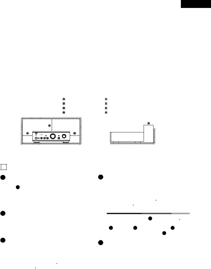
PRECAUTIONS FOR INSTALLATION
For heat dispersal, leave at least 10 cm of space between the top, back and sides of this unit and the wall or other components.
SICHERHEITSMASSNAHMEN BEIM EINBAU
Lassen Sie zur Wärmeverteilung mindestens 10 cm Raum zwischen der Oberseite, der Rückseite und den Seiten des Gerätes und der Wand oder anderen Komponenten.
PRECAUTIONS D’INSTALLATION
Afin de disperser la chaleur, laisser un espace d’au moins 10 cm entre le haut, l’arrière les côtés de cet appareil et le mur ou un autre composant.
PRECAUZIONI PER L’INSTALLAZIONE
Per consentire una buona dispersione del calore, lasciate uno spazio di almeno 10 cm tra le parti superiore, posteriore e laterali di quest’unità e le parete o gli altri componenti.
PRECAUCIONES A TOMAR DURANTE LA INSTALACIÓN
Para que el calor se disipe, deje por lo menos 10 cm de espacio entre las partes superior, posterior y laterales de esta unidad y la pared u otros componentes.
VOORZORGSMAATREGELEN VOOR INSTALLATIE
Laat voor een goede warmteafvoer minstens 10 cm ruimte tussen de boven-, achteren zijkanten van dit toestel en de muur of andere elementen.
OBSERVERA VID INSTALLATIONEN
För god värmeavledning, bör du lämna ett utrymme på minst 10 cm ovanför, bakom och på sidorna av apparaten och väggen eller andra komponenter.
PRECAUÇÕES DE INSTALAÇÃO
Para a dissipação do calor, deixar pelo menos 10 cm de espaço entre o topo, a parte de trás e os lados desta unidade e a parede ou outros componentes.
10 cm or more |
10 cm o más |
10 cm oder mehr |
10 cm of meer |
10 cm ou plus |
10 cm eller mer |
10 cm o piu |
10 cm ou mais |
Wall
Wand
Mur
Parete
Pared
Muur
Vägg
Parede
1 DESIGNATIONS AND FUNCTIONS OF PANEL CONTROLS (Refer to page 5)
1Power switch (POWER)
When the power switch is turned ON ( ), the power LED 11 lights.
When the power switch is turned ON, power is supplied to the unit. It takes a few seconds after the power is turned on for the unit to warm up. This is due to the built-in muting circuit that eliminates noise during the on/ off operation.
2Headphone jack (PHONES)
4Treble control (TREBLE)
This knob is used to control the treble quality of the sound. When the knob is set at the center position, the frequency characteristics are flattened in the range above 1000 Hz. The treble is emphasized as the knob is moved off center to the right ( ), and reduced as it is moved to the left (
  ).
).
NOTE:
This jack is used to plug in the headphones.
(The SPEAKER output is turned off when the headphones are plugged in.)
To prevent hearing loss, do not raise the volume level excessively when using headphones.
3Bass control (BASS)
This knob is used to control the bass quality of the sound. When the knob is set at the center position, the frequency characteristics are flattened in the range below 1000 Hz. The bass is emphasized as the knob is
moved off center to the right ( ), and reduced as it is moved to the left (
  ).
).
When the Volume control 7 is turned right ( ) from the center position, the adjustment range of the BASS
3 , TREBLE 4 and LOUDNESS 5 controls
decreases. If the Volume control 7 is turned fully right the bass and treble cannot be adjusted.
5Loudness Switch (LOUDNESS)
When the volume is low, it is difficult for the human ear to clearly distinguish notes in the low and high frequency ranges. The loudness switch allows a simple “onetouch” correction of this difficulty. Press the loudness
switch ON ( ) when listening to music at a low volume. The low notes and high notes will be corrected to produce a natural sound.
7

ENGLISH
6Balance control (BALANCE)
This knob is used to adjust the balance between the left and right channels.
When it is set to the center position, the amplitude of the amplifier is equal on both sides. If the volume on the
right side is too low, turn the knob to the right ( ). If the volume on the left side is too low, turn the knob to the left
(  ). This will achieve an even balance on the left and right sides.
7Volume control (VOLUME)
This knob controls the overall volume level.
Turn the knob to the right ( ) to raise the volume and to the left (
  ) to lower it.
8Recording output select switch (REC OUT SELECTOR)
Use this to select the output source for recording onto a tape deck, etc.
•TAPE-2  1:
1:
Use this position when making copies of tapes using two tape decks. The input signal from the deck connected to the TAPE-2/MD input terminals is fed to the TAPE-1/DAT REC OUT terminals.
•TAPE-1  2:
2:
Use this position when making copies of tapes using two tape decks. The input signal from the deck connected to the TAPE-1/DAT input terminals is fed to the TAPE-2/MD REC OUT terminals.
•PHONO:
Used to recording from the turntable.
•CD:
Used to recording from the CD player.
•TUNER:
Used to recording from the tuner.
•DVD/AUX:
Used to recording component that connected to the DVD/ AUX terminals.
9Input select switch (INPUT SELECTOR)
This switch is used to select the input signal for the program source.
•TAPE-2/MD:
Use this position when using the tape deck, etc., connected to the TAPE-2/MD terminals.
•TAPE-1/DAT:
Use this position when using the tape deck, etc., connected to the TAPE-1/DAT terminals.
•PHONO:
Use this position when using the record player connected to the PHONO terminals.
Use the CARTRIDGE selection switch 17 to switch the sensitivity to correspond to the cartridge type being used.
•CD:
Used to listen a compact disc player or other component that is connected to the CD terminals.
•TUNER:
Used to play a component such as an FM/AM tuner or a TV tuner that is connected to the TUNER terminals.
•DVD/AUX:
Used to play a component such as a HiFi video player, TV tuner or tape deck that is connected to the DVD/AUX terminals.
10Source direct switch (SOURCE DIRECT)
The controls (BASS 3 , TREBLE 4 , LOUDNESS 5
and BALANCE 6 ) can be used when this switch is in
the OFF ( ) position.
When set to the ON ( ) position, the above controls are by passed and the signals are input directly to the volume control circuit, providing high quality sound.
11Power LED
The LED indicates the set‘s operating mode.
Main unit |
Main unit mode |
LED color |
|||||
power switch |
|||||||
|
|
|
|
|
|||
|
|
|
|
|
|
|
|
|
|
Operating |
Lit orange |
|
|||
|
|
|
|
|
|
|
|
ON ( |
) |
Mute |
Flashing |
|
|||
green |
|
|
orange |
||||
|
|
|
|||||
|
|
|
|
|
|
|
|
|
|
Standby (power off |
Lit red |
|
|||
|
|
by remote control) |
|
||||
|
|
|
|
|
|
||
|
|
|
|
|
|
|
|
OFF ( |
) |
|
Off |
|
|||
|
|
|
|
|
|
|
|
The mute mode is set for several seconds when the main unit’s power switch is turned ON ( ) or when the standby mode is canceled by the remote control unit.
12Remote Control Sensor (REMOTE SENSOR)
This sensor receives the infra-red light transmitted from the wireless remote control unit.
For remote control, point the wireless remote control unit towards the sensor.
13Iput terminals (INPUTS)
These are input terminals for CD players, turntables, AM/FM tuners, tape decks or other playback components.
NOTES:
•The PHONO input terminals are equipped with a short pin-plug. Remove this plug to connect a record player.
Store the removed short pin-plug in a safe place so as not to lose it.
•Do not plug a short pin plug into the REC (recording output) terminals. Doing so will result in a loss of sound and may damage connected equipment.
14Tape playback and recording terminals (TAPE-1/DAT, TAPE-2/MD)
Playback and Recording Terminals
•Playback Terminals (PB).
•Recording Terminals (REC).
15Pre out terminals (PRE OUT)
Use these when adding a power amplifier, a subwoofer with built-in power amplifier, etc.
Connect these PRE OUT terminals to the input terminals on the additional power amplifier, subwoofer, etc.
NOTE:
Signals are output from the PRE OUT terminals even when using headphones.
If you wish to stop the signals, do so by operating the connected unit (power amplifier, etc.).
8

16Speaker system terminals (SPEAKER SYSTEMS)
Connect the speaker systems here.
17Cartridge selection switch (CARTRIDGE)
This switch is set according to the type of player cartridge to be used.
Set this switch to MM ( ) or MC (
 ) according to the type of cartridge used on your turntable.
18Ground terminal (SIGNAL GND)
Connect the turntable’s ground wire here.
NOTE:
This terminal is used to reduce noise when a turntable, etc., is connected.
It does not provide complete grounding.
19Attachment plug receptacles (AC OUTLETS)
AC outlets are used for connecting amplifier component units, such as tuner, turntable, tape deck, etc.
•SWITCHED
These outlets are turned ON/OFF when main power switch is turned on/off.
20AC inlet receptacle (AC IN)
Connect the included power supply cord here.
Do not use any other cord than the provided power supply cord.
ENGLISH
2 CONNECTIONS
Connecting the speakers
■Speaker impedance
•When using speaker systems A and B separately, speakers with an impedance of 4 to 16 Ω/ohms can be connected.
•When bi-wiring with bi-wireable speaker system, speakers with an impedance of 4 to 16 Ω/ohms can be connected.
•Note that when using two sets of speaker systems together (A + B), using speakers with an impedance other than between 8 to 16 Ω/ohms can result in damage.
Note that this unit is not equipped with a switch for selecting the speaker system. The A and B speaker output terminals are connected in parallel.
•The protective circuit may be activated if speakers with other impedances are connected.
■Be sure to connect the cords between the speaker terminals and speaker systems with the same polarities ( to
to
 ,
,  to
to  ). If not, the central sound will be weak and the position of the different instruments will not be clear, diminishing the stereo effect.
■When connecting the speakers, be sure that the core wires of the speaker cords do not stick out from the terminals and touch other terminals, each other or the rear panel.
■Connecting the speaker cords
1. Peel off the sheathing from the end of the cord. 2. Twist the core wires.
3. Turn the speaker terminal counterclockwise to loosen it.
4. Insert the core wires entirely, then turn the terminal clockwise to tighten it.
CAUTION:
NEVER touch the speaker terminals when the power is on.
Doing so could result in electric shocks.
NOTE:
Protector Circuit
This set is equipped with a built-in high speed protector circuit.This circuit protects the speakers should the amplifier’s outputs be short-circuited or the surrounding temperature be abnormal. When the protector circuit is activated, the speaker output is automatically interrupted. Should this happen, turn off the set’s power, check the speaker cable connections once again, then turn the power back on. The set will operate normally once the muting circuit turns off after several seconds.
9

ENGLISH
Cautions on Connections
•Do not plug in the power suppy cord until all connections are completed.
•Be sure to connect the left and right channels properly.
•Insert the plugs securely. Incomplete connections can result in noise.
•Use the SWITCHED AC OUTLETS to plug in audio components. Do not use them for hair dryers or other appliances.
•Note that placing the pin plug cords next to power supply cords or near power transformers may result in humming or other noise.
•The PHONO input jacks have an extremely high sensitivity, so avoid turning up the volume when no pin plug cords are connected. Doing so may result in induction humming (booming) from the speakers. When pin plug cords are not connected, insert the included short-circuit pin plug.
Tuner |
DVD player (sound only) |
Tape deck or DAT deck |
Power amplifier
SPEAKER SYSTEM (A)
Power supply cord
Turntable
(for MC, MM)
 Ground wire
* Connectground the wire, but disconnect it if humming or other
noise is generated.
Tape deck MD or recorder
|
SPEAKER SYSTEM (BI-WIRING) |
|
When bi-wiring with bi-wireable |
CD player |
speakers, connect the mid and |
high range terminals to SYSTEM |
|
|
(A) (or SYSTEM (B)), the low |
SPEAKER SYSTEM (B) |
range terminals to SYSTEM (B) |
|
|
|
(or SYSTEM (A)). |
10
3 OPERATION (Refer to Page 5)
PREPARATION
1.CHECKING CONNECTIONS
•Make sure that all the connections are proper by referring to the rear panel.
•Check the polarity (positive and negative) of connections, and the directivity of stereo separation (right cord to right channel terminal, and left cord to left channel terminal).
•Check the directivity of pin cord connection.
2.SETTING OF EACH KNOB
•Turn the volume control knob 7 left (  ), to minimum position.
•Set the tone controls 3 , 4 and balance control 6 to center position.
• Set the LOUDNESS switch 5 to “OFF ( )”.
)”.
• Set the SOURCE DIRECT switch 10 to “OFF ( )”.
)”.
After checking the above items, turn on the power, the amplifier is set in the ready mode in a few seconds.
PLAYING A RECORD
1.Set the CARTRIDGE selection switch 17 “MC ( )” or “MM (
 )”.
)”.
2.Set the INPUT SELECTOR switch 9 to “PHONO”.
3.Operate the turntable and play the record.
4.Turn the volume 7 and tone controls 3 , 4 and bal-
ance control 6 to yield an appropriate volume and sound quality.
PLAYBACK OF CD PLAYER
1.Set the INPUT SELECTOR switch 9 to “CD”.
2.Operate the CD player.
3.Turn the volume 7 and tone controls 3 , 4 and bal-
ance control 6 to yield an appropriate volume and sound quality.
RECEPTION OF RADIO PROGRAMS
1.Set the INPUT SELECTOR switch 9 to “TUNER”.
2.Operate the tuner to receive a radio program.
3.Turn the volume 7 and tone controls 3 , 4 and bal-
ance control 6 to yield an appropriate volume and sound quality.
CONNECTIONS OF AUDIO EQUIPMENT TO DVD/ AUX TERMINALS
1.Set the INPUT SELECTOR switch 9 to “DVD/AUX” position.
2.Operate the Audio equipment Systems.
3.Turn the volume 7 and tone controls 3 , 4 and bal-
ance control 6 to yield an appropriate volume and sound quality.
ENGLISH
PLAYBACK WITH TAPE DECK, DAT, MD
1.Set the INPUT SELECTOR switch 9 to “TAPE-1/DAT” or “TAPE-2/MD”.
2.Operate the Tape Deck, DAT, MD.
3.Turn the volume 7 and tone controls 3 , 4 and bal-
ance control 6 to yield an appropriate volume and sound quality.
RECORDING WITH TAPE DECK, DAT, MD
1.Set the REC OUT SELECTOR switch 8 to the program source you wish to record.
2.Start the playback of the program source.
3.Start recording with the component connected to “TAPE- 1/DAT” or “TAPE-2/MD”.
•In the PMA-1500RII, the REC OUT signal and the speaker (headphone) signal are output via separate circuits so that knobs and switches related to the tone and volume have no effect what so ever on the sound that is recorded. Also, since the recording function is selected
by the REC OUT SELECTOR switch 8 , the free program source can be played through the speakers (or headphones) even during recording.
MONITORING THE RECORDING
•A recording in progress can be monitored if a tape deck with three individual heads for recording and playback is used. A tape deck in which a common head is used for both recording and playback cannot be used to monitor recording.
When a recording is being made using TAPE-1/DAT, selecting TAPE-1/DAT with the INPUT SELECTOR will engage the RECORDING MONITOR and permit a check of the recording condition.
11
ENGLISH
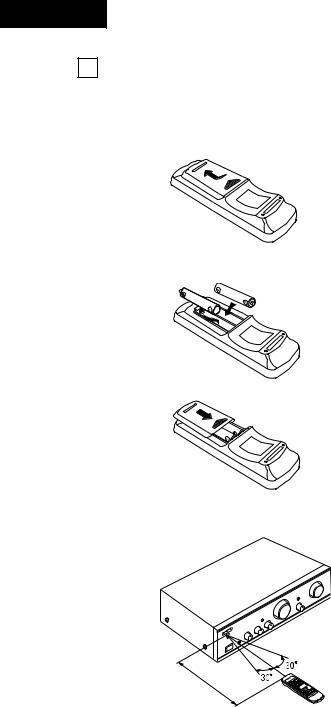
4 REMOTE CONTROL OPERATION
The accessory Remote Control Unit is used to control the amplifier from a convenient distance.
■Inserting the Dry Cell Batteries
1.Remove the battery cover on the Remote Control Unit.
2.Insert two dry cell batteries as shown in the diagram on the battery supply unit.
3.Replace the battery cover.
Notes on Battery Usage
■RC-885 uses the size R6P (AA) dry cell batteries.
■The batteries will need to be replaced approximately once a year. This will depend upon how often the Remote Control Unit is used.
■If, in less than a year from the time new batteries were inserted, the Remote Control Unit fails to operate the Amplifier from a near-by position, it is time to replace the batteries.
■The included battery is only for verifying operation. Replace it with a new battery as soon as possible.
■Insert the batteries properly, following the polarity diagram inside the battery compartment.
■Batteries are prone to damage and leakage. Therefore:
•Do not mix new batteries with used ones.
•Do not mix different types of batteries.
•Do not jumper opposite poles of the batteries, expose them to heat, break them open, nor expose them to open fire.
■If the batteries have leaked, remove any traces of battery fluid from the battery compartment wiping thoroughly with a dry cloth. Then insert new batteries.
■ Directions for use
■ Operate the Remote Control Unit while pointing it towards the Remote Control Sensor on the Amplifier as shown in the diagram on the left.
■ The Remote Control Unit can be used at distances up to about 8 meters in a straight line from the amplifier. This distance will decrease if there are obstructions blocking the infra-red light transmission or if the Remote Control Unit is not directed straight at the amplifier.
Approx. 8 m
Note on operation
•Do not press the operating buttons on the Amplifier and the Remote Control Unit at the same time. This will cause misoperation.
•Operation of the Remote Control Unit will become less effective or erratic if the infrared Remote Control Sensor on the Amplifier is exposed to strong light or if there are obstructions between the Remote Control Unit and the sensor.
•In case you operate a VCR, TV or other components by remote control, do not operate buttons on two different remote control units at the same time. This will cause misoperation.
Besides being able to operate the PMA-1500RII Integrated-amplifier with this Remote Control Unit, you can also operate a DENON cassette deck, MD recorder, tuner and
CD player with this handy full-system Remote Control Unit.
12
ENGLISH
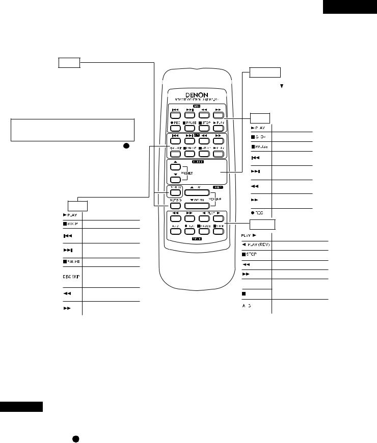
Remote Control Unit RC-885 supplied with the PMA-1500RII
AMP
POWER button
This button can be used to turn on the power and set standby mode of the amplifier.
However, this button can be used to switch the power between the on and standby modes when and only when the power supply cord is plugged in and the main unit’s power switch is set to the on/standby mode.
This button will not function if there is a power failure, if the power supply cord is not plugged in, or when using an audio timer.
This button can be used when the power LED 11 is lit.
MUTING button
Pressing this switch will activate the muting condition and no signals will be output to the speakers.
Other buttons
Other buttons are exclusively for the PMA-1500RII, and function in the same way as the corresponding buttons on the set.
CD
PLAY button
STOP button
Reverse Track
Search button
Forward Track
Search button
PAUSE button
Refer to the operating instructions of your DENON CD player
Manual Search
Reverse button
Manual Search
Forward button
TUNER
PRESET  buttons
Press this button to move up or down among the preset station numbers.
MD
PLAY button
STOP button
PAUSE button
Reverse Track
Search button
Forward Track
Search button
Manual Search
Reverse button
Manual Search
Forward button
Record button
DECK
PLAY button
PLAY (REV) button
STOP button
REWIND button
FORWARD button


 Refer to the operating instructions of your

 DENON tape deck
A/B DECK
SELECT button
•The RC-885 Remote Control Unit can control CD players, MD recorder, tuners and cassette decks manufactured by DENON.
•Note that operation may not be possible for some models.
•Buttons are conveniently separated into groups, each group controlling one specific component. The groups are AMP, CD, MD, DECK and TUNER.
For details on operating other components, refer to the operating instructions for the CD player, MD recorder, tuners and cassette deck.
CAUTION:
•If the power is turned off with the Remote Control Unit, the set is switched to the power stand-by state. If you are absent for a long period of time, unplug the power supply cord.
•Only the power LED 11 lights when in the power stand-by mode.
•You may experience erratic operation of the Remote Control Unit if it is operated in fluorescent light and direct sunlight, in particular if this light strikes the Remote Control Sensor on the Amplifier. However, this is not a malfunction, and if this should happen, simply protect the sensor against such light.
13

ENGLISH
5TROUBLESHOOTING
■Check the following before assuming there is a problem with the set.
1.Are all connections proper ?
2.Is the set being operated as described in the operating instructions ?
3.Are the speakers and input components being operated properly ?
If the set does not seem to be operating properly, check the points listed below. If these points do not apply, the set may be damaged. Turn off the power immediately and contact your store of purchase.
Symptom |
|
|
Cause |
|
|
Measures |
|
Page |
|
|
|
|
|
||||
Common problems arising when listening to the CD,MD,records, tapes, and FM broadcasts, etc. |
|
|||||||
|
|
|
|
|
|
|||
Power LED does not light and no |
• |
Power supply cord is not con- |
• Check that the cord is plugged in. |
|
10 |
|||
sound is produced when POWER |
|
nected. |
|
|
|
|
|
|
switch is turned on. |
|
|
|
|
|
|
|
|
|
|
|
|
|
|
|
||
|
• |
Speaker cords not properly con- |
• |
Connect securely. |
|
9, 10 |
||
Power LED lights but no sound is |
|
nected. |
|
|
|
|
|
|
• |
lNPUT |
SELECTOR |
not set to |
• Set to the proper position. |
|
8, 11 |
||
produced. |
|
|||||||
|
proper position. |
|
|
|
|
|
||
|
|
|
|
|
|
|
||
|
• |
VOLUME control turned down. |
• Set to an appropriate level. |
|
8, 11 |
|||
|
|
|
|
|
|
|
||
|
• |
Speaker cords not properly con- |
• |
Connect securely. |
|
9, 10 |
||
Sound is not produced from one |
|
nected. |
|
|
|
|
|
|
• |
Input cords not properly connected. |
• |
Connect securely. |
|
10 |
|||
side only. |
|
|||||||
• |
Left/right |
balance |
improperly |
• Adjust the BALANCE control. |
|
8, 11 |
||
|
|
|||||||
|
|
adjusted. |
|
|
|
|
|
|
|
|
|
|
|
|
|
||
Volume level is different when lis- |
• |
Tuner and record outputs different. |
• |
Adjust the tuner output to the turn- |
|
- |
||
|
|
|
|
|
table’s output (if the tuner is |
|
|
|
tening to tuner and records. |
|
|
|
|
|
|
|
|
|
|
|
|
|
equipped with an output control). |
|
|
|
|
|
|
|
|
|
|
|
|
|
|
|
|
|
|
|||
Positions of instruments inverted for |
• |
Left and right speakers or input |
• Check the left/right connections. |
|
9, 10 |
|||
stereo sources. |
|
cords inverted. |
|
|
|
|
|
|
|
|
|
|
|
|
|||
|
|
Problems occurring when playing records. |
|
|||||
|
|
|
|
|
|
|
||
|
• |
Turntable’s ground wire not con- |
• |
Connect securely. |
|
10 |
||
|
|
nected. |
|
|
• |
Connect securely. |
|
|
Booming sound produced when |
• |
Input cords not properly connected |
|
10 |
||||
playing records. |
|
to PHONO terminals. |
|
|
|
|
|
|
|
• |
Influence from a TV or VCR near |
• Change the position of installation. |
|
- |
|||
|
|
the turntable. |
|
|
|
|
|
|
|
|
|
|
|
|
|||
|
• |
Turntable and speaker systems are |
• Move speaker systems as far away |
|
- |
|||
|
|
too close. |
|
|
as possible. |
|
- |
|
Howling produced when volume is |
• |
Floor is soft and vibrates easily. |
• |
Use cushions to absorb the vibra- |
|
|||
|
|
|
|
|
tions transmitted from the floor to |
|
|
|
turned up while playing records. |
|
|
|
|
|
|
|
|
|
|
|
|
|
the speakers. If the turntable does |
|
|
|
|
|
|
|
|
|
|
|
|
|
|
|
|
|
|
not include insulators, use audio |
|
|
|
|
|
|
|
|
insulators, available in stores. |
|
|
|
|
|
|
|
|
|
||
|
• |
Stylus pressure is too light. |
• |
Apply proper pressure. |
|
- |
||
Sound is distorted. |
• |
Dirt on tip of stylus. |
|
• Check the tip of the stylus. |
|
- |
||
|
• |
Defective cartridge. |
|
• |
Replace the cartridge. |
|
- |
|
|
|
|
|
|
|
|
|
|
Remote control unit.
This unit does not operate properly when remote control unit is used.
• |
Batteries dead. |
|
|
• Replace with new batteries. |
12 |
||
• Remote |
control unit too |
far |
from |
• |
Move closer. |
12 |
|
|
this unit. |
|
|
|
• |
Remove obstacle. |
12 |
• Obstacle |
between this |
unit |
and |
||||
|
remote control unit. |
|
|
|
|
|
|
• Different button is being pressed. |
• Press the proper button. |
13 |
|||||
• |
and |
ends of battery inserted |
• |
Insert batteries properly. |
12 |
||
|
in reverse. |
|
|
|
|
|
|
|
|
|
|
|
|
|
|
14

ENGLISH
6SPECIFICATIONS
■POWER AMPLIFIER SECTION Rated Output Power:
Both channel driven
(8Ω /ohms Load) |
70 W + 70 W (20 Hz to 20 kHz, T.H.D. 0.07 %) |
(4 Ω/ohms Load) |
140 W + 140 W (DIN, 1 kHz, T.H.D. 0.7 %) |
Total Harmonic Distortion: |
0.01 % (–3 dB at rated output, 8 Ω/ohms) (1 kHz) |
■ PRE AMPLIFIER SECTION |
|
Rated Output: |
150 mV (Recout Terminal) |
Input Sensitivity/Input Impedance: |
|
The value in parentheses ( |
) refers to |
the input impedance when SOURCE |
|
DIRECT is ON. |
|
PHONO: |
MM: 2.5 mV/47 kΩ/kohms |
|
MC: 200 µV/100 Ω/ohms |
CD, TUNER, DVD/AUX, |
150 mV/47 kΩ/kohms |
TAPE-1/DAT, TAPE-2/MD |
(150 mV/13 kΩ/kohms) |
RIAA Deviation: |
|
PHONO: |
MM: 20 Hz ~ 20 kHz ±0.5 dB |
|
MC: 30 Hz ~ 20 kHz ±0.5 dB |
■ OVERALL CHARACTERISTICS |
|
SN Ratio (IHF A Network): |
PHONO |
|
MM: 91 dB (at 5 mV input) |
|
(input terminals short-circuited) MC: 76 dB (at 0.5 mV input) |
SOURCE-DIRECT: ON |
CD, TUNER, DVD/AUX, TAPE-1/DAT, TAPE-2/MD: 110 dB |
Frequency response |
5 Hz ~ 100 kHz (0 ~ –3dB) |
Tone Control Adjustable Range: |
|
BASS: |
100 Hz ±8 dB |
TREBLE: |
10 kHz ±8 dB |
■ OTHERS |
|
Power Supply: |
AC 230 V, 50 Hz |
AC Outlets: |
|
Switched x 3: |
100 W (Total) |
Power Consumption: |
305 W (IEC) |
|
2 W MAX (Standby) |
Dimensions: |
434 (W) x 134 (H) x 407 (D) mm |
|
(17-3/32” x 5-9/32” x 16-1/32”) |
Weight: |
14.6 kg (32 lbs 3 oz) |
■ REMOTE CONTROL UNIT (RC-885) |
|
Remote control system: |
Infrared pulse system |
Power supply: |
3 V DC, Two size R6P (AA) dry cell batteries |
External dimensions: |
54 (W) x 155 (H) x 29 (D) mm |
|
(2-1/8” x 6-7/64” x 1-9/64”) |
Weight: |
100 g (including batteries) |
Maximum dimensions include controls, jacks, and covers.
(W) = width, (H) = height, (D) = depth
• For improvement purposes, specifications and functions are subject to change without advanced notice.
15

DEUTSCH
1 BEZEICHNUNGEN UND FUNKTIONEN DER BEDIENUNGSELEMENTE
(Beziehen Sie sich auf Seite 5)
1Netztaste (POWER)
Wenn der Netzschalter eingeschaltet (ON) ( ) ist, leuchtet das POWER LED 11 .
Der Verstärker wird durch Drücken dieser Taste eingeschaltet. Nach dem Einschalten braucht das Gerät einige Sekunden, bis es betriebsbereit ist, da hierbei der Stummschaltungskreis zur Unterdrückung des normalerweise beim Einschalten einer Stereoanlage auftretenden Knackgeräusches aktiviert wird.
2Kopfhörerbuchse (PHONES)
Für den Anschluß von Stereo-Kopfhörern.
(Der SPEAKERAusgang (Vorverstärker) ist ausgeschaltet, wenn Kopfhörer angeschlossen worden sind.) Erhöhen Sie bei der Verwendung von Kopfhörern die Lautstärke nicht übermäßig, um Gehörschäden vorzubeugen.
3Tiefenregler (BASS)
Mit diesem Regler läßt sich der Anteil der tiefen Frequenzen einstellen. In Mittelstellung des Reglers ist der Frequenzgang im Bereich unterhalb 1000 Hz linear, d.h. unmodifiziert. Die Tiefen können durch Drehen des
Reglers nach rechts ( ) verstärkt, durch Drehen nach links (
  ) vermindert werden.
4Höhenregler (TREBLE)
Mit diesem Regler läßt sich der Anteil der hohen Frequenzen einstellen. In Mittelstellung des Reglers ist der Frequenzgang im Bereich oberhalb 1000 Hz linear, d.h. unmodifiziert. Die Höhen können durch Drehen des Reglers nach rechts ( ) verstärkt, durch Drehen nach links (
  ) vermindert werden.
HINWEIS:
Wenn der Lautstärkeregler 7 von der Mittelposition aus nach rechts ( ) gedreht wird, verringert sich die Reichweite der BASS- 3 , TREBLE- 4 und LOUD- NESS-Regler 5 . Befindet sich der Lautstärkeregler
7 in ganz rechter Position, dann ist eine Einstellung der Tiefen und Höhen nicht möglich.
5Loudness-Schalter (LOUDNESS)
Bei niedrig eingestellter Lautstärke ist es für das menschliche Gehör schwierig, in den Niederund Hochfrequenzbereichen verhandene Akzente deutlich zu unterscheiden. Der Loudness-Schalter ermöglicht die Korrektur dieser Schwierigkeit mit nur einem Tasten-
druck. Drücken Sie den Loudness-Schalter auf ON ( ), wenn Sie sich Musik mit niedrig eingestellter Lautstärke anhören. Die niedrigen und hohen Akzente werden für einen natürlichen Klang korrigiert.
6Balanceregler (BALANCE)
Mit diesem Regler wird die Balance zwischen linkem und rechtem Kanal eingestellt. In Mittelstellung ist die verstärkung für beide Kanäle gleich.
Wenn die Lautstärke des rechten Kanals zu niedrig ist, muß der Regler nach rechts ( ) gedreht werden, bei zu
niedrigen Lautstärke des linken Kanals nach links (  ). Hierdurch läßt sich die Balance zwischen linkem und rechtem Kanal wieder herstellen.
7Lautstärkeregler (VOLUME)
Mit diesem Regler wird die Gesamtlautstärke eingestellt. Die Lautstärke wird durch Drehen des Reglers nach
rechts ( ) angehoben, durch Drehen nach links (
  ) vermindert.
8Aufnahme-Ausgangsshalter (REC OUT SELECTOR)
Wählen Sie mit diesem Wähler die Ausgangsquelle für die Aufnahme auf ein Cassettendeck o.ä. aus.
•TAPE-2  1:
1:
Wählen Sie diese Position, wenn Sie Bandkopien mit zwei Cassettendecks erstellen. Das Eingangssignal des an die TAPE-2/MD-Eingangsbuchsen angeschlossenen Decks wird zu den TAPE-1/DAT REC OUT Buchsen geleitet.
•TAPE-1  2:
2:
Wählen Sie diese Position, wenn Sie Bandkopien mit zwei Cassettendecks erstellen. Das Eingangssignal des an die TAPE-1/DAT-Eingangsbuchsen angeschlossenen Decks wird zu den TAPE-2/MD REC OUT Buchsen geleitet.
•PHONO:
Einstellung bei Aufnahme von dem Plattenspieler.
•CD:
Einstellung bei Aufnahme von dem CD-Spieler.
•TUNER:
Einstellung bei Aufnahme von dem Tuner.
•DVD/AUX:
Einstellung bei Aufnahme von der Komponente, die an die DVD/AUX Buchsen angeschlossen ist.
9Eingangswähler (INPUT SELECTOR)
Dieser Schalter wird zum Einstellen des Eingangssignals für die Programmquelle benutzt.
•TAPE-2/MD:
Wählen Sie diese Position, wenn Sie das an die TAPE-2/MD-Buchsen angeschlossene Cassettendeck usw. benutzen.
•TAPE-1/DAT:
Wählen Sie diese Position, wenn Sie das an die TAPE-1/DAT-Buchsen angeschlossene Cassettendeck usw. benutzen.
•PHONO:
Wählen Sie diese Position, wenn Sie den an die PHONO-Buchsen angeschlossenen Plattenspieler benutzen.
Auswählen des Ausgangs von einem Plattenspieler, der an die PHONO-Buchsen angeschlossen ist.
Benutzen Sie den CARTRIDGE-Wahlschalter 17 um die Empfindlichkeit dem benutzten Tonabnehmertyp entsprechend einzustellen.
•CD:
Für Wiedergabe mit einem CD-Spieler bzw. einem anderen an die CD-Buchsen angeschlossenen Gerät.
•TUNER:
Für Wiedergabe mit einem an die TUNER-Buchsen angeschlossene Gerät, z.B. einem UKW/AM-Tuner oder einem Fernseh-Empfänger.
•DVD/AUX:
Für die Wiedergabe von einer an die DVD/AUX Buchsen angeschlossenen Komponente wie z.B. eines HiFi-Video-spielers, TV-Tuners oder Cassettendecks.
16

10Direktquellenschalter (SOURCE DIRECT)
Die Regler (BASS 3 , TREBLE 4 , LOUDNESS 5 und BALANCE 6 ) können betätigt werden, wenn sich
dieser Schalter in der Position OFF ( ) befindet. Befindet sich der Schalter auf der Position ON (
 ), werden die oben aufgeführten Regler umgangen und die Signale werden direkt zur Lautstärkeregler-Steuerung eingegeben. Dies garantiert einen hochqualitativen Klang.
11POWER LED
Das LED zeigt den Betriebsmodus der Anlage an.
Hauptschalter |
Hauptgerät- |
LED-Farbe |
||||
|
Ein |
Modus |
||||
|
|
|
|
|||
|
|
|
|
|
|
|
|
|
Betrieb |
|
Leuchtet orange |
||
|
|
|
|
|
|
|
|
|
Stummschaltung |
Blinkt |
|
|
|
ON ( |
) |
grün |
|
orange |
||
|
|
|
||||
|
|
|
|
|
||
|
|
Standby |
(Auss- |
|
|
|
|
|
chalten mit |
Fern- |
Leuchtet rot |
||
|
|
bedienung) |
|
|
|
|
|
|
|
|
|
|
|
OFF( |
) |
|
|
Aus |
|
|
|
|
|
|
|
|
|
Der Stummschaltmodus ist für einige Sekunden eingestellt, wenn der Netzschalter des Hauptgerätes auf ON ( ) gestellt wird oder wenn der Standby-Modus mit Hilfe der Fernbedienung entaktiviert worden ist.
12Fernbedienungssensor (REMOTE SENSOR)
Dieser Sensor fängt die von der drahtlosen Fernbedienung übermittelten infraroten Lichtstrahlen auf.
Soll eine Fernbedienung durchgeführt werden, ist die drahtlose Fernbedienung direkt auf das Sensorfenster zu richten.
13Eingänge (INPUTS)
Dies sind Eingangsbuchsen für CD-Spieler, Plattenspieler, AM/FM-Tuner, Cassettendecks oder andere Wiedergabegeräte.
HINWEIS:
•Die PHONO-Eingangsklemmen sind mit einem kurzen Stiftstecker ausgestattet. Entfernen Sie diesen Stecker für den Anschluß eines Plattenspielers.
Bewahren Sie den entfernten Stiftstecker an einem sicheren Ort auf, wo Sie ihn nicht verlieren.
•Stecken Sie keinen Kurzstiftstecker in die REC Klemmen (Aufnahme-Ausgang) ein. Dies könnte sowohl zu einem Klangverlust als auch zu Beschädigungen der angeschlossenen Geräte führen.
14Cassettenband-Wiedergabe- und AufnahmeAnschlüsse (TAPE-1/DAT, TAPE-2/MD)
Wiedergabeund Aufnahmebuchsen.
•Wiedergabebuchsen (PB).
•Aufnahmebuchsen (REC).
DEUTSCH
15Pre-out Anschlussklemmen (PRE OUT)
Diese sind zu verwenden, wenn ein Endverstärker, ein Tiefsttonlautsprecher mit eingebauten Endverstärker u.ä. angeschlossen wird.
Die PRE-OUT-Anschlussklemmen mit den Eingangsanschlüssen des zusätzlichen Endverstärkers, Tiefstton- lauts-prechers usw. verbinden.
HINWEIS:
Der Signalausgang der PRE-OUT-Anschlüsse erfolgt auch bei Benutzung eines Kopfhörers.
Wenn Signalausgang gestoppt werden soll, muss hierzu das angeschlossene Gerät (Endverstärker usw.) bedient werden.
16Lautsprechersystem (SPEAKER SYSTEMS)
Schließen Sie die Lautsprechersysteme hier an.
17Tonabnehmer-wahlschalter (CARTRIDGE)
Dieser Schalter wird entsprechend des verwendeten Tonabnehmertyps eingestellt.
Stellen Sie diesen Schalter auf MM ( ) oder auf MC (
 ) — je nachdem, welchen Tonabnehmertyp Ihr Plattenspieler verwendet.
18Erdungsklemme (SIGNAL GND)
Schließen Sie die Erdungsleitung des Plattenspielers hier an.
HINWEIS:
Diese Anschlußklemme dient zur Reduzierung von Störungen, wenn ein Plattenspieler o.ä. angeschlossen worden ist; sorgt jedoch nicht für eine komplette Erdung.
19Anschlusssteckerbuchsen (AC OUTLETS)
Die Wechselstromausgänge sind für den Anschluß von Verstärkernkomponenten wie z.B. für einen Tuner, Plattenspieler, Cassettendeck usw. vorgesehen.
•SWITCHED
Diese Ausgänge werden einund ausgeschaltet (ON/ OFF), wenn der Hauptstromschalter ein-/ausge- schaltet wird.
20Wechselstromsteckdose (AC IN)
Das mitgelieferte Netzkabel hier anschließen. Verwenden Sie ausschließlich das mitgelieferte Wech- selstrom-Netzkabel.
17

DEUTSCH
2 ANSCHLÜSSE
Anschließen der Lautsprecher
■Lautsprecherimpedanz
•Bei getrennter Benutzung der Lautsprechersysteme A und B, können Lautsprecher mit einer Impedanz von 4 bis 16 Ω/Ohm angeschlossen werden.
•Bei der Doppelverdrahtung mit einem doppelt-ver- drahtbarem Lautsprechersystem, können Lautsprecher mit einer Impedanz von 4 bis 16Ω/Ohm angeschlossen werden.
•Bedenken Sie bei der Verwendung von zwei Lautsprechersets zusammen (A + B), daß die Benutzung von Lautsprechern mit einer anderen Impedanz als zwischen 8 und 16Ω/Ohm Beschädigungen verursachen kann.
Dieses Gerät ist nicht mit einem Schalter für die Anwahl des Lautsprechersystems ausgestattet. Die A- und B-Lautsprecherausgänge sind parallel miteinander verbunden.
•Die Schutzschaltung könnte aktiviert werden, wenn Sie Lautsprecher mit einer anderen Impedanz zur Anwendung bringen.
■Achten Sie darauf, daß Sie die Kabel zwischen den Lautsprecherklemmen und den Lautsprechersystemen
mit den gleichen Polaritäten ( an
an  ,
,  an
an  ) anschließen. Andernfalls ist der Mittelklang schwach und die Position der verschiedenen Instrumente ist undeutlich. Dies verringert den Stereo-Effekt.
■Achten Sie beim Anschließen der Lautsprecher darauf, daß die Kabeladern nicht aus den Klemmen herausragen und andere Klemmen, sich gegenseitig oder die Rückseite des Gerätes berühren.
■Anschließen der Lautsprecherkabel
1. Streifen Sie die Mantelung vom Ende des Kabels ab. 2. Drehen Sie die Kabeladern.
3. Drehen Sie die Lautsprecherklemme entgegen des Uhrzeigersinns, um sie zu lösen.
4. Setzen Sie die Kabeladern vollständig ein und drehen Sie die Klemme dann im Uhrzeigersinn, um sie wieder zu befestigen.
VORSICHT:
Berühren Sie die Lautsprecherklemmen NIEMALS, wenn der Strom eingeschaltet ist.
Dies könnte einen elektrischen Schlag verursachen.
HINWEIS:
Schutzschaltung
Diese Anlage ist mit einer eingebauten Hochgeschwind- igkeits-Schaltung ausgestattet. Bei einem Kurzschluss der Verstärkerausgänge oder einer abnormalen Umgebungstemperatur schützt diese Schaltung die Lautsprecher. Wenn die Schutzschaltung aktiviert ist, wird der Lautsprecherausgang automatisch unterbrochen. Schalten Sie in einem solchen Fall die Stromversorgung zur Anlage aus, überprüfen Sie noch einmal die LautsprecherkabelAnschlüsse und schalten Sie die Stromversorgung anschließend wieder ein. Einige Sekunden nach dem Ausschalten der Stummschaltung ist der Normalbetrieb wiederhergestellt.
Vorsichtsmaßnahmen zu den Anschlüssen
•Schließen Sie das Netzkabel erst an, wenn Sie alle anderen Anschlüsse ausgeführt haben.
•Achten Sie darauf, daß Sie die linken und rechten Kanäle richtig anschließen.
•Setzen Sie die Stecker fest ein. Lose Anschlüsse können Störungen verursachen.
•An die geschalteten AC-Ausgänge (SWITCHED AC) können Audio-Komponenten angeschlossen werden. Schließen Sie an diese Ausgänge keine Haartrockner oder ähnliche Geräte an.
•Bitte beachten Sie, dass es zu Summen oder anderen Geräuschen kommen kann, wenn die Stiftstecker-Kabel neben Netzkabeln oder Stromtransformatoren liegen.
•Die PHONO-Eingangsbuchsen haben eine außergewöhnlich hohe Empfindlichkeit. Vermeiden Sie daher das Erhöhen der Lautstärke, wenn keine Stiftstekkerkabel angeschlossen sind. Andernfalls kann es zu einem Induktionsbrummen (dröhnen) von den Lautsprechern kommen. Setzen Sie für den Fall, daß keine Stiftsteckerkabel angeschlossen sind, die mitgelieferten Kurzschluß-Stiftstekker ein.
18
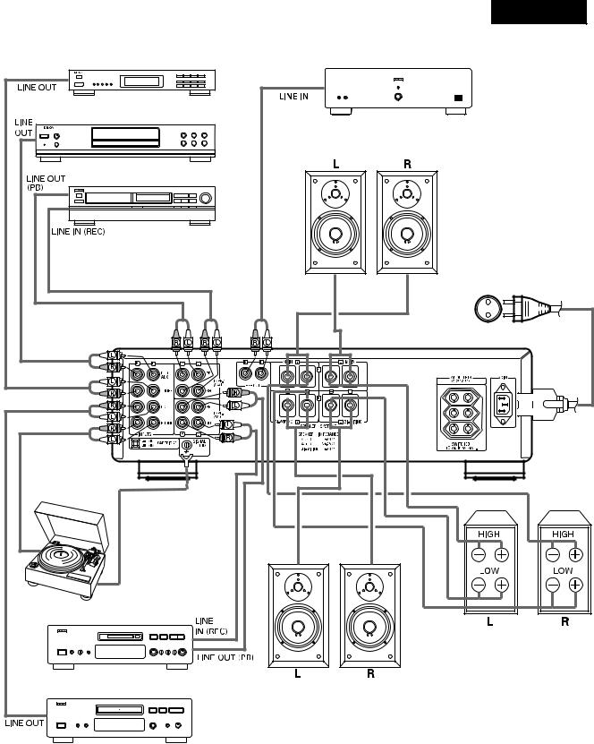
DEUTSCH
Tuner |
Endverstäker |
DVD-Spieler (nur Audio) |
|
|
SPEAKER SYSTEM (A) |
|
(Lautsprechersystem) |
Cassetten-Deck oder DAT-Recorder |
|
|
Netzkabel |
Plattenspieler
(für MC, MM)
 Erdungskabel
*Schließen Sie die Erdungsleitung an.
Trennen Sie sie jedoch wieder ab, wenn Brummen oder andere Geräusche auftreten.
Cassetten-Deck oder
Minidisc-Recorder
CD-Spieler
SPEAKER SYSTEM (B) (Lautsprechersystem)
SPEAKER SYSTEM (Lautsprechersystem) (BIVerdrahtung)
Bei der zweifachen Verdrahtung mit entsprechenden Lautsprechern, schließen Sie die Mittel-und Hochbereich-Klemmen an SYSTEM
(A) (oder SYSTEM (B)) an. Nehmen Sie den Anschluß der NiederbereichKlemmen an SYSTEM (B) (oder SYSTEM (A)) vor.
19

DEUTSCH
3 BETRIEB (Beziehen Sie sich auf Seite 5)
VORBEREITUNG
1.DIE ANSCHLÜSSE ÜBERPRÜFEN
•Vergewissern Sie sich durch einen Vergleich mit der Rückseite, daß alle Anschlüsse korrekt durchgeführt wurden.
•Überprüfen Sie die Polarität (positiv und negativ) der Anschlüsse und die Richtwirkung der Stereotrennung (rechtes Kabel zur Rechtskanalklemme und linkes Kabel zur Linkskanalklemme).
•Überprüfen Sie die Richtwirkung des Stiftkabelanschlußes.
2.EINSTELLUNG DER EINZELNEN KNÖPFE
•Drehen Sie den Lautstärkeregler 7 entgegen den Uhrzeigersinn auf (  ) die Minimum-Position.
• Die Tonsteuerungen 3 , 4 und die Abgleichsteuerung
6in die Mittelposition einstellen.
•Einstellen des Lautstärke (LOUDNESS)-Schalters 5 auf “OFF (aus) ( )”.
)”.
•Stellen Sie den Tonquellen Direktschalter (SOURCE DIRECT) 10 auf die Position “OFF (aus) ( )”.
)”.
Schalten Sie den Strom nach Überprüfung der o.g. Punkte ein. Der Verstärker setzt sich dann innerhalb von wenigen Sekunden in Betriebsbereitschaft.
EINE SCHALLPLATTE ABSPIELEN
1.Stellen Sie den Tonabnehmer-wahlschalter 17 auf “MC ( )” oder “MM (
 )”.
)”.
2.Stellen Sie den Eingangswähler (INPUT SELECTOR)
9auf die Position ”PHONO” (Plattenspieler).
3.Bedienen Sie den Plattenspieler, und spielen Sie die Schallplatte ab.
4.Drehen Sie den Lautstärke-Regler 7 , die Klangregler
3 , 4 und den Balance-Regler 6 auf die Position, die für die Lautstärke und Klangqualität geeignete Position.
WIEDERGABE DES CD-SPIELERS
1. Stellen Sie den Eingangswähler (INPUT SELECTOR)
9auf die Position “CD”.
2.Bedienen Sie den CD-Spieler, und spielen Sie die CDPlatte ab.
3.Drehen Sie den Lautstärke-Regler 7 , die Klangregler
3 , 4 und den Balance-Regler 6 auf die Position, die für die Lautstärke und Klangqualität geeignete Position.
EMPFANG VON RADIOPROGRAMMEN
1. Stellen Sie den Eingangswähler (INPUT SELECTOR)
9auf die Position “TUNER”.
2.Bedienen Sie den Tuner, damit ein Sender empfangen werden kann.
3.Drehen Sie den Lautstärke-Regler 7 , die Klangregler
3 , 4 und den Balance-Regler 6 auf die Position, die für die Lautstärke und Klangqualität geeignete Position.
ANSCHLUSS VON WEITERER AUDIO-AUSRÜS- TUNG BEI DEN DVD/AUX-KLEMMEN
1. Stellen Sie den Eingangswähler (INPUT SELECTOR)
9auf die Position “DVD/AUX”.
2.Bedienen Sie die Audio-Ausrüstung.
3.Drehen Sie den Lautstärke-Regler 7 , die Klangregler
3 , 4 und den Balance-Regler 6 auf die Position, die für die Lautstärke und Klangqualität geeignete Position.
WIEDERGABE MIT EINEM CASSETTENDECK, DAT-DECK, MD-REKORDER
1. Stellen Sie den Eingangswähler (INPUT SELECTOR)
9auf die Position “TAPE-1/DAT” oder “TAPE-2/MD”.
2.Betreiben Sie das Cassettendeck, das DAT-Deck, den MDRekorder.
3.Drehen Sie den Lautstärke-Regler 7 , die Klangregler
3 , 4 und den Balance-Regler 6 auf die Position, die für die Lautstärke und Klangqualität geeignete Position.
AUFNAHME MIT EINEM CASSETTENDECK, DATDECK, MD-REKORDER
1.Stellen Sie den REC OUT SELECTOR-Schalter 8 auf die Programmquelle, die Sie aufnehmen möchten.
2.Beginnen Sie die Wiedergabe der Programmquelle.
3.Beginnen Sie die Aufnahme mit dem Gerät, das bei den Buchsen “TAPE-1/DAT” oder “TAPE-2/MD” angeschlos-
sen ist.
•Im PMA-1500RII werden das REC OUT-Signal und das Lautsprecher-Signal (Kopfhörer) über separate Schaltkreise ausgegeben, so daß sämtliche mit dem Klang und der Lautstärke in Zusammenhang stehende Knöpfe und Schalter keinen Effekt auf den aufgenommenen Ton haben. Da also die Aufnahme-Funktion mit dem
REC OUT SELECTOR-Schalter 8 angewählt wird, kann die freie Programmquelle selbst während der Aufnahme über die Lautsprecher (oder Kopfhörer) wiedergegeben werden.
DIE AUFNAHME MITANHÖREN
•Eine Aufnahme kann mitangehört werden, wenn ein Kassettendeck mit drei verschiedenen Tonköpfen für Aufnahme und Wiedergabe verwendet wird. Bei einem Kassettendeck, dessen Tonkopf sowohl für die Aufnahme als auch die Wiedergabe benutzt wird, kann die Aufnahme nicht mitangehört werden. Wenn eine Aufnahme mit Anschluß bei der Buchse “TAPE-1/DAT” durchgeführt wird, wobei der Eingangswähler (INPUT SELECTOR) auf “TAPE-1/DAT” eingestellt ist, wird der Aufnahme-Monitor (RECORDING MONITOR) eingeschaltet und damit eine Kontrolle der Aufnahmebedingungen gestattet.
20
DEUTSCH
4 FERNBEDIENUNG
Die als Sonderzubehör erhältliche Fernbedienung kann dazu benutzt werden, den Verstärker vom Sessel aus zu bedienen.
■Einlegen der Trockenbatterien
1.Nehmen Sie den Batteriedeckel der Fernbedienung ab.
2.Legen Sie zwei Trockenbatterien wie im Batteriefach angezeigt ein.
3.Legen Sie den Batteriedeckel wieder auf.
■Hinweise zur Anwendung der Fernbedienung
Ca. 8 Meter
Hinweis zur Bedienung
Hinweise zum Gebrauch von Batterien
■Für die Fernbedienung RC-885 werden Trockenbatterien vom Typ R6P (AA) benötigt.
■Die Batterien müssen nach etwa einem Jahr ausgewechselt werden. Es hängt jedoch davon ab, wie oft und wie lange Sie Ihre Fernbedienung anwenden.
■Kann der Verstärker nach einer kürzeren Zeit als einem Jahr nach Batteriewechsel nicht mit der Fernbedienung bedient werden (auch nicht aus nächster Distanz), ist es an der Zeit, die Batterien auszuwechseln.
■Die im Lieferumfang enthaltene Batterie dient ausschließlich Prüfzwecken.Tauschen Sie die Batterie so schnell wie möglich gegen eine neue Batterie aus.
■Legen Sie die Batterien ordnungsgemäß ein und folgen Sie dabei den Hinweisen im Batteriefach bezüglich der Polarität der Batterien.
■Batterien können leicht beschädigt werden oder auslaufen.
Beachten Sie bitte deshalb:
•Verwenden Sie niemals neue Batterien zusammen mit alten.
•Legen Sie nur Batterien des gleichen Typs ein.
•Die Gegenpole der Batterien dürfen nicht überbrückt werden. Die Batterien dürfen weder extremer Hitze oder einem offenen Feuer ausgesetzt noch gewaltsam geöffnet werden.
■Sollten Batterien ausgelaufen sein, muß die ausgelaufene Batterieflüssigkeit restlos aus dem Batteriefach mit einem weichen Tuch entfernt werden. Danach können neue Batterien eingelegt werden.
■Richten Sie die Fernbedienung direkt auf den Fernbedienungssensor des Verstärkers (wie in der linken Abbildung gezeigt) und drücken Sie dann auf die entsprechende(n) Bedienungstaste(n).
■Die Fernbedienung kann innerhalb eines Radius von ungefähr 8 m zum Verstärker benutzt werden.
Dieser Radius nimmt u.U. ab, wenn die infraroten Lichtstrahlen von sich im Wege befindlichen Gegenständen blockiert oder umgeleitet werden oder wenn die Fernbedienung nicht direkt auf den Verstärker gerichtet wird.
•Drücken Sie die Bedienungstasten des Verstärkers und die der Fernbedienung nicht zur gleichen Zeit. Sie vermeiden damit das Auftreten von Fehlfunktionen.
•Die Betrieb der Fernbedienung ist weniger effektiv bzw. irregulär, wenn der infrarote Fernbedienungs-Sensor des Verstärkers unter starker Sonneneinstrahlung steht oder wenn sich zwischen Fernbedienung und Sensor größere Gegenstände befinden.
•Wenn Sie Ihren Videorekorder, Fernseher oder andere Komponenten ebenfalls mit einer Fernbedienung steuern, sollten die Bedienungstasten zweier verschiedener Fernbedienungen nicht zur gleichen Zeit gedrückt werden. Sie vermeiden damit das Auftreten von Fehlfunktionen.
Mit diesem Fernbedienungsgerät können Sie nicht nur den PMA-1500RII integrierten Verstärker betreiben, sondern diese handliche Vollsystem-Fernbedienung ermöglicht auch der Betrieb eines DENON
Cassettendecks, MD-Rekorders, Tuners und CD-Players möglich.
21
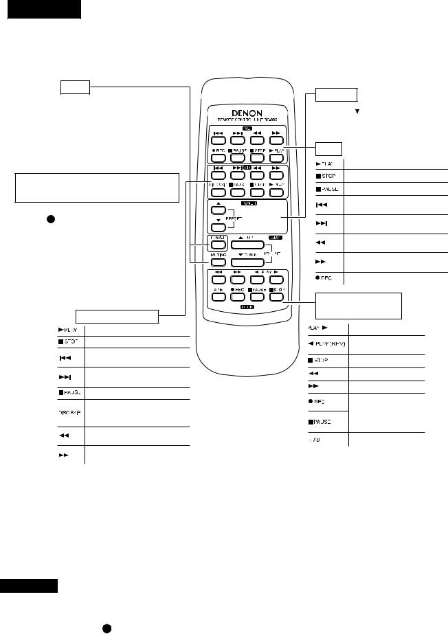
DEUTSCH
Fernbedienung RC-885 und der mitgelieferte PMA-1500RII
AMP
POWER-Taste Netztasten
Mit dieser Taste kann das Gerät eingeschaltet und der Standby-Modus des Verstärkers eingestellt werden. Dennoch können Sie mit dieser Taste zwischen dem Ein-und Standby-Modus hin-und herschalten, wennund nur wenn-das Netzkabel angeschlossen und der Netzschalter des Hauptgerätes auf den Ein-/Standby- Modus gestellt ist.
Diese Taste ist nach einem Stromausfall, bei abgezogenen Netzkabel und bei Anwendung eines Audio-Timers außer Betrieb gesetzt.
Diese Taste kann betätigt werden, wenn die POWER LED (Netz) 11 leuchtet.
MUTING-Taste
Nach einem Druck auf diese Taste wird die Stummabstimmung aktiviert und es erfolgt keine Tonausgabe über die Lautsprecher.
Andere Tasten
Die andere Tasten sind ausschließlich für den PMA-1500Rll bestimmt und funktionieren wie die entsprechenden Tasten an diesem Gerät.
CD-SPIELER (CD)
Abspieltaste
Stopptaste
Taste für den automatischen
Suchlauf in Rückwärtsrichtung
Taste für den automatischen
Suchlauf in Vorwärtsrichtung
Pausenta
Beziehen Sie sich auf die
Bedienungsanleitung für
Ihren DENON CD-Spieler
Taste für den manuellen
Suchlauf in Rückwärtsrichtung
Taste für den manuellen
Suchlauf in Vorwärtsrichtung
TUNER
PRESET  -Taste
Mit Hife dieser Taste können Sie in der Liste der Speichernummern auf-und abblättern.
MD
Abspieltaste
Stopptaste
Pausenta
Taste für den automatischen
Suchlauf in Rückwärtsrichtung
Taste für den automatischen
Suchlauf in Vorwärtsrichtung
Taste für den manuellen
Suchlauf in Rückwärtsrichtung
Taste für den manuellen
Suchlauf in Vorwärtsrichtung
REC-Taste (Aufnahme)
CASSETTEDECK (DECK)
Abspieltaste
Wiedergabe-/
Räcksuchlauftaste
Stopptaste
Rückspultaste
Vorwärtstaste
Siehe in der Bedienungsanleitung für Cassettendeck von DENON
A/B Deck Wahltaste
•Mit der Fernbedienung RC-885 können von DENON hergestellte CD-Player, MD-Rekorder, Tuner und Cassettendecks gesteuert werden.
•Beachten Sie bitte, daß der Betrieb bei einige Modellen nicht möglich ist.
•Die Bedienungstasten sind in verschiedenen Gruppen zusammengefaßt, jede Gruppe steuert jeweils eine Komponente. Es gibt eine Gruppeneinteilung für folgende Komponenten: AMP, FUNCTION, CD, MD, DECK, TUNER usw.
Einzelheiten zum Betrieb anderer Komponenten entnehmen Sie bitte den Bedienungsanleitungen für den CD-Player, MDRekorder, Tuner und/oder Cassettendeck.
ACHTUNG:
•Wenn der Strom mit dem Fernbedienungsgerät ausgeschaltet worden ist, schaltet sich die Anlage in Strom-Betrieb- sbereitschaft. Wenn Sie für längere Zeit abwesend sind, trennen Sie vorher das Netzkabel von der Netzsteckdose ab.
•Nur das POWER LED 11 leuchtet, wenn sich das Gerät im Standby-Modus befindet.
•Wenn die Fernbedienung unter fluoreszierenden Lichtverhältnissen oder bei Sonnenlichteinfall betätigt wird, kann es zu Situationen kommen, unter denen die Fernbedienung nicht einwandfrei arbeiten kann. Das ist besonders dann der Fall, wenn ein solches Licht auf den Fernbedienungs-Sensor des Verstärkers fällt. Es liegt dann keine Fehlfunktion vor. Es ist lediglich dafür zu sorgen, daß der Sensor diesem Lichteinfall nicht weiter ausgesetzt wird.
22

DEUTSCH
5FEHLERSUCHE
■Überprüfen Sie die nachfolgend aufgeführten Punkte, bevor Sie davon ausgehen, daß es sich um eine Gerätestörung handelt.
1.Sind alle Anschlüsse ordnungsgemäß ausgeführt worden ?
2.Wird die Anlage gemäß der Bedienungsanleitung betrieben ?
3.Werden die Lautsprecher und Eingangskomponenten ordnungsgemäß betrieben ?
Wenn die Anlage nicht ordnungsgemäß zu arbeiten scheint, überprüfen Sie zunächst die nachfolgend aufgeführten Punkte. Läßt sich die Störung dennoch nicht beheben, schalten Sie sofort den Strom aus und kontaktieren Sie Ihren Händler.
Sympthom |
Ursache |
Abhilfe |
Seite |
|
|
|
|
Herkömmliche Störungen, die beim Anhören von CDs, Schallplatten, Cassettenbändern und UKW-Rundfunksend- ungen usw. auftreten.
Das POWER LED leuchtet nicht und |
• |
Das Netzkabel ist nicht angeschlossen |
• Überprüfen Sie den Anschluß des Netzk- |
19 |
|
es wird kein Ton ausgegeben,wenn |
|
worden. |
|
abels. |
|
der POWER-Schalter eingeschaltet |
|
|
|
|
|
wird. |
|
|
|
|
|
|
|
|
|
|
|
|
• |
Die Lautsprecherkabel sind falsch ange- |
• Schließen Sie die Kabel fest an. |
17, 18 |
|
|
|
schlossen worden. |
|
|
|
POWER LED leuchtet, aber es ist |
• Der Eingangswähler (INPUT SELECTOR) |
• |
Stellen Sie den Eingangswähler (INPUT |
16, 20 |
|
|
wurde nicht auf die richtige Position gest- |
|
SELECTOR) auf die richtige Position. |
|
|
kein Ton zu hören. |
|
|
|
||
|
ellt. |
|
|
|
|
|
|
|
|
|
|
|
• |
Der Lautstärke-Regler (VOLUME) wurde |
• Stellen Sie die Lautstärke auf einen |
16, 20 |
|
|
|
heruntergedreht. |
|
geeigneten Pegel ein. |
|
|
|
|
|
|
|
|
• |
Die Lautsprecherkabel sind falsch ange- |
• Schließen Sie die Kabel fest an. |
18, 19 |
|
|
|
schlossen worden. |
|
|
|
Der Ton wird nur von einer Seite |
• |
Die Eingangskabel sind falsch angeschlos- |
• Schließen Sie die Kabel fest an. |
19 |
|
produziert. |
|
sen worden. |
|
|
|
|
• |
Die Balance zwischen dem linken und |
• Stellen Sie die Balance-Regler (BAL- |
16, 20 |
|
|
|
rechten Kanal ist nicht richtig eingestellt. |
|
ANCE) ein. |
|
|
|
|
|
|
|
Der Lautstärkepegel ist beim |
• |
Die Tunerund Plattenspielerausgänge |
• Stellen Sie den Tuner-Ausgang entspre- |
- |
|
Anhören eines Rundfunkprogramms |
|
sind unterschiedlich. |
|
chend des Plattenspieler-Ausgangs ein |
|
anders als beim Anhören von Schall- |
|
|
|
(wenn der Tuner mit einem Ausgangsre- |
|
platten. |
|
|
|
gler ausgestattet ist). |
|
|
|
|
|
|
|
Die Positionen der Instrumente sind |
• |
Der linke und rechte Lautsprecher oder die |
• |
Überprüfen Sie die linken/rechten |
18, 19 |
bei Stereo-Tonquellen umgedreht. |
|
Eingangskabel sind umgedreht. |
|
Anschlüsse. |
|
|
|
|
|
|
|
Störungen, die beim Abspielen von Schallplatten auftreten.
|
• |
Das Erdungskabel des Plattenspielers ist |
• Schließen Sie das Erdungskabel fest an. |
19 |
|||
|
|
nicht angeschlossen worden. |
|
|
|
|
|
Während des Abspielens von Schall- |
• Die Eingangskabel sind nicht richtig an die |
• Schließen Sie die Kabel fest an. |
19 |
||||
|
PHONO-Buchsen angeschlossen worden. |
|
|
|
|
||
platten ist ein Dröhnen zu hören. |
|
• Ändern Sie den Aufstellort. |
|
- |
|||
• |
Beeinträchtigung von einem sich in der |
|
|||||
|
|
||||||
|
|
Nähe befindlichen Fernsehgerät oder |
|
|
|
|
|
|
|
VCR. |
|
|
|
|
|
|
|
|
|
|
|||
|
• |
Der Plattenspieler und die Lautsprecher- |
• Stellen Sie die Lautsprecher so weit wie |
- |
|||
|
|
systeme sind zu dicht zueinander aufgest- |
möglich vom Plattenspieler entfernt auf. |
|
|||
Während des Abspielens von Schall- |
|
ellt worden. |
|
|
|
|
|
• Der Fußboden ist weich und vibriert leicht. |
• Verwenden Sie Puffer, um die vom Fuß- |
- |
|||||
platten tritt beim Erhöhen der |
|||||||
|
|
boden zu |
den Lautsprechern über- |
|
|||
Lautstärke Rückkopplungspfeiffen |
|
|
|
||||
|
|
tragenen |
Vibrationen |
aufzufangen. |
|
||
auf. |
|
|
|
||||
|
|
Verwenden Sie im Handel erhältliche |
|
||||
|
|
|
|
||||
|
|
|
Audio-Isolatoren, wenn der Plattenspieler |
|
|||
|
|
|
nicht mit Isolatoren ausgestattet ist. |
|
|||
|
|
|
|
||||
|
• Der Nadeldruck ist zu gering. |
• Fügen Sie den richtigen Druck hinzu. |
- |
||||
Der Ton ist verzerrt. |
• |
Die Nadelspitze ist verschmutzt. |
• Überprüfen Sie die Nadelspitze. |
- |
|||
|
• Der Tonabnehmer ist defekt. |
• Tauschen Sie den Tonabnehmer aus. |
- |
||||
|
|
|
|
|
|
|
|
Fernbedienungsgerät.
Dieses Gerät funktioniert bei Anwendung des Fernbedienungsgerätes nichteinwandfrei.
• Die Batterien sind leer. |
|
|
• Legen Sie neue Batterien ein. |
21 |
• Die Enftfernung zwischen dem Fernbedie- |
• Gehen Sie dichter an den Receiver |
21 |
||
nungsgerät und diesem Gerät ist zu groß. |
heran. |
|
||
• Zwischen diesem Gerät und dem Fernbe- |
• Beseitigen Sie das Hindernis. |
21 |
||
dienungsgerät befinden sich Hindernisse. |
|
|
||
• Es wurde eine andere Taste gedrückt. |
• Drücken Sie die richtige Taste. |
22 |
||
• Die Batterie-Enden |
und |
wurden |
• Legen Sie die Batterien richtig ein. |
21 |
falsch herum eingelegt. |
|
|
|
|
|
|
|
|
|
23

DEUTSCH
6TECHNISCHE DATEN
■LEISTUNGSENDS VERSTÄRKER Nenn-Ausgangsleistung:
Beide Kanäle betroebem
(an 8 Ω/Ohm) |
70 W + 70 W (20 Hz bis 20 kHz, T.H.D. 0,07 %) |
(an 4 Ω/Ohm) |
140W + 140 W (DIN, 1 kHz, T.H.D. 0,7 %) |
Gesamtklirrfaktor: |
0,01 % (–3 dB bei Nennausgang, 8 Ω/Ohm) (1 kHz) |
■ VORVERSTÄRKER |
|
Nenn-Ausgangsleistung:
Eingangsempfindlichkeit/
Eingangsimpedanz:
Der in Klammen ( ) angegebeneWer bezieht sich auf die Eingangsimpedanz, wenn der QuellenDirektschalter
(SOURCE DIRECT) eingeschaltet (ON) ist. PHONO:
150 mV (Aufnahme-Ausgangsbuchse)
MM: 2,5 mV/47 kΩ/kOhm
MC: 200 µV/100 Ω/Ohm
CD, TUNER, DVD/AUX, |
150 mV/47 kΩ/kOhm |
TAPE-1/DAT, TAPE-2/MD |
(150 mV/13 kΩ/kOhm) |
Abweichung von der RIAA-Kennlinie: |
|
PHONO: |
MM: 20 Hz ~ 20 kHz ±0,5 dB |
|
MC: 30 Hz ~ 20 kHz ±0,5 dB |
■ GESAMTEIGENSCHAFTEN |
|
Signal/Rauschabstand |
|
(IHF-A-Weiche): |
PHONO |
|
MM: 91 dB (bei einem 5 mV-Eingang) |
|
(Eingängekurzgeschlossen) MC: 76 dB (bei einem 0,5 mV-Eingang) |
SOURCE-DIRECT: ON |
CD, TUNER, DVD/AUX, TAPE-1/DAT, TAPE-2/MD: 110 dB |
Frequenzgang: |
5 Hz ~ 100 kHz (0 ~ –3dB) |
Klangregelbereich: |
|
TIEFEN (BASS): |
100 Hz ±8 dB |
HÖHEN (TREBLE): |
10 kHz ±8 dB |
■ SONSTIGES |
|
Netzspannung und-frequenz: |
230 V Wechselstrom, 50 Hz |
Wechselstrom-Ausgänge: |
|
Geschaltet x 3: |
100 W (Gesamte) |
Leistungsaufnahme: |
305 W (IEC) |
|
MAX.2W (Standby) |
Abmessungen: |
434 (B) x 134 (H) x 407 (T) mm |
Nettogewicht: |
14,6 kg |
■ FERNBEDIENUNGSGERÄT (RC-885) |
|
Fernbedienungsgerät: |
Infrarot-Impulssystem |
Stromversorgung: |
3 V Gleichstrom, zwei R6P (AA) Trockenzellbatterien |
Äußere Abmessungen: |
54 (B) x 155 (H) x 29 (T) mm |
Gewicht: |
100 g (einschließlich Batterien) |
Die Abmessungen schließen Regler, Buchsen und Abdeckungen mit ein.
(B) = Breite, (H) = Höhe, (T) = Tiefe
• Änderungen der technischen Daten und Funktion zum Zwecke der Verbesserung ohne Ankündingung vorbehalten.
24

FRANCAIS
1 NOMENCLATURE ET FONCTIONS DES COMMANDES DE PANNEAU
(Se reporter à la page 5)
1Interrupteur d’alimentation (POWER)
Lorsque le commutateur d’alimentation est sur ON ( ), l’indicateur POWER LED 11 s’allume.
Lorsque l’interrupteur est pressé, l’appareil est mis sous tension. Il faut quelques secondes à l’appareil pour chauffer après la mise sous tension. Cela à cause du circuit de sourdine incorporé pour éliminer le bruit lors de la mise sous/hors tension.
2Prise de casque (PHONES)
Cette prise sert à brancher le casque.
(La sortie SPEAKER (sortie préamplifiée) est désactivée lorsque le casque est branché.)
Afin d’éviter une perte de I’ouïe, ne pas augmenter excessivement le niveau du volume lors de I’utilisation d’écouteurs.
3Réglage de la tonalité grave (BASS)
Ce bouton sert au réglage de la qualité des sons graves. Lorsqu’il est placé au centre, les caractéristiques de fréquences sont aplanies sortie dans la gamme au-des- sous de 1000 Hz. Les sons graves sont accentués en
tournant le bouton vers la droite ( ), et réduits en le tournant versla gauche (
  ).
).
4Réglage de la tonalité aiguë (TREBLE)
Ce bouton sert au réglage de la qualité des sons aigus. Lorsqu’il est placé au centre, les caractéristiques de fréquences sont aplanies dans la gamme au-dessous de 1000 Hz. Les sons aigus sont accentués en tournant
le bouton vers la droite ( ), et réduits en le tournant vers la gauche (
  ).
).
REMARQUE:
Lorsque la commande de volume 7 est tournée vers la droite ( ) à partir de la position centrale, la plage de réglage des commandes BASS (graves) 3 , TREBLE (aiguës) 4 et LOUDNESS (commutateur de sonorité) 5 diminue. Lorsque la commande de vol-
ume 7 est tournée complètement vers la droite, les graves et les aiguës ne peuvent pas être ajustées.
5Commutateur de sonorité (LOUDNESS)
Lorsque le volume est bas, I’oreille humaine distingue difficilement les notes dans les gammes de basses et de hautes fréquences. Le commutateur de sonorité permet une correction de cette difficulté par “simple pression d’une touche”. Appuyer sur le commutateur de sonorité
pour le mettre en position d’activation ON ( ) pour I’écoute de musique à faible volume. Les notes basses et les notes hautes seront corrigées pour produire un son naturel.
6Réglage de l’équilibrage (BALANCE)
Ce bouton sert à régler la distribution du volume sonore entre les canaux droit et gauche. S’il est réglé au centre, l’amplitude de l’amplificateur est la même aux deux canaux. Si le volume du canal de droite est trop bas,
tourner le bouton vers la droite ( ). Si celui de gauche
est trop bas, tourner le bouton vers la gauche (  ). Cela établira l’équilibrage des canaux droit et gauche.
7Commande de volume (VOLUME)
Ce bouton sert à ajuster le nniveau sonore global.
Tourner ce bouton vers la droite ( ) pour augmenter le volume et vers la gauche (
  ) pour le réduire.
8Sélecteur de sortie d’enregistrement (REC OUT SELECTOR)
Utiliser ce sélecteur pour sélectionner la source de sortie pour l’enregistrement sur une platine cassette, etc.
•TAPE-2  1:
1:
Utiliser cette position lors de copies de bandes utilisant deux platines cassettes. Le signal d’entrée de la platine connectée aux bornes d’entrée de TAPE-2/MD est transmis aux bornes de TAPE-1/DAT REC OUT.
•TAPE-1  2:
2:
Utiliser cette position lors de copies de bandes utilisant deux platines cassettes. Le signal d’entrée de la platine connectée aux bornes d’entrée de TAPE-1/ DAT est transmis aux bornes de TAPE-2/MD REC OUT.
•PHONO:
Utilisé pour enregistrer à partir d’une platine tournedisque.
•CD:
Utilisé pour enregistrer à partir d’un lecteur de disque compact.
•TUNER:
Utilisé pour enregistrer à partir d’un syntoniseur.
•DVD/AUX:
Utilisé pour enregistrer à partir d’un appareil connecté aux bornes DVD/ AUX.
9Sélecteur d’entrée (INPUT SELECTOR)
Ce sélecteur est utilisé pour sélectionner le signal d’entrée pour la source de programme.
•TAPE-2/MD:
Utiliser cette position lors de l’utilisation de la platine cassette, etc., connectée aux bornes TAPE-2/MD.
•TAPE-1/DAT:
Utiliser cette position lors de l’utilisation de la platine cassette, etc., connectée aux bornes TAPE-1/DAT.
•PHONO:
Utiliser cette position lors de l’utilisation du lecteur de disque connecté aux bornes PHONO.
Utiliser le commutateur de sélection de cellule (CAR-
TRIDGE) 17 pour commuter a sensibilité et la faire correspondre au type de cellule utilisée.
•CD:
Utilisé pour l’écoute d’un lecteur de disque compact ou d’un autre appareil connecté aux bornes CD.
•TUNER:
Utilisé pour la lecture sur un appareil tel qu’un tuner FM/AM ou tuner TV connecté aux bornes TUNER.
•DVD/AUX:
Utilisé pour la lecture sur un appareil tel qu’un lecteur vidéo Hi-Fi, un tuner TV ou une platine cassette connecté aux bornes DVD/AUX.
25
 Loading...