

Page 1

HIGH FREQUENCYSECONDARY RECTIFIER
MAJORPRODUCT CHARACTERISTICS
STTH2003CT/CG/CF
I
F(AV)
V
RRM
2 x 10 A
300 V
Tj (max) 175 °C
(max) 1 V
V
F
trr(max) 35 ns
FEATURESAND BENEFITS
COMBINESHIGHESTRECOVERYAND
REVERSEVOLTAGEPERFORMANCE
ULTRA-FAST, SOFTANDNOISE-FREE
RECOVERY
DESCRIPTION
Dual center tap Fast Recovery Epitaxial Diodes
suited for Switch Mode Power Supply and high
frequencyDC/DC converters.
Packaged in TO-220AB, ISOWATT220AB or
2
D
PAK, this device is especially intended for
secondaryrectification.
ABSOLUTE RATINGS (limitingvalues, perdiode)
A1
A2
TO-220AB
STTH2003CT
A1
K
K
A2
A1
2
PAK
D
STTH2003CG
A2
K
A1
A2
K
ISOWATT220AB
STTH2003CF
Symbol Parameter Value Unit
V
RRM
I
F(RMS)
I
F(AV)
Repetitivepeakreverse voltage
RMSforwardcurrent
Averageforward
current δ =0.5
I
FSM
I
RSM
T
stg
Tj
October 1999 - Ed: 6C
Surgenonrepetitiveforwardcurrent tp = 10ms sinusoidal
Non repetitiveavalanche current tp = 20 µs square
Storagetemperaturerange
Maximumoperatingjunction temperature
TO-220AB/ D2PAK
ISOWATT220AB
Tc=140°C Perdiode
Perdevice
Tc=125°C
300 V
30 A
10
20
110 A
5A
-65+ 175 °C
175 °C
A
1/7
Page 2
STTH2003CT/CG/CF
THERMAL RESISTANCES
Symbol Parameter Value Unit
R
th (j-c)
Junctionto case TO-220AB/ D2PAK
ISOWATT220AB
R
th (c)
TO-220AB/ D2PAK
ISOWATT220AB
STATICELECTRICALCHARACTERISTICS (perdiode)
Symbol Parameter Testsconditions Min. Typ. Max. Unit
Per diode 2.5 °C/W
Total 1.3
Per diode 3.9
Total 3.2
Coupling 0.1
Coupling 2.5
*
I
R
Reverseleakage
current
V
**
F
Forwardvoltagedrop I
=300V Tj = 25°C
V
R
Tj = 125°C
=10A Tj=25°C
F
Tj = 125°C
30 300
0.85 1
20 µA
1.25 V
Pulsetest: * tp= 5 ms, δ <2%
** tp = 380 µs, δ <2%
Toevaluatethemaximum conductionlossesuse the following equation:
P= 0.75x I
F(AV)
+ 0.025I
F2(RMS)
RECOVERYCHARACTERISTICS
Symbol Tests conditions Min. Typ. Max. Unit
trr
tfr
V
FP
= 0.5 A Irr= 0.25A IR=1A Tj=25°C
I
F
I
=1A dIF/dt= - 50 A/µsVR=30V
F
I
=10A dIF/dt= 100 A/µs
F
=1.1 x VFmax.
V
FR
Tj = 25°C
25 ns
35
230 ns
3.5 V
2/7
S
factor
I
RM
Vcc =200V IF=10A
dI
/dt = 200 A/µs
F
Tj = 125°C
0.3 8A
Page 3
STTH2003CT/CG/CF
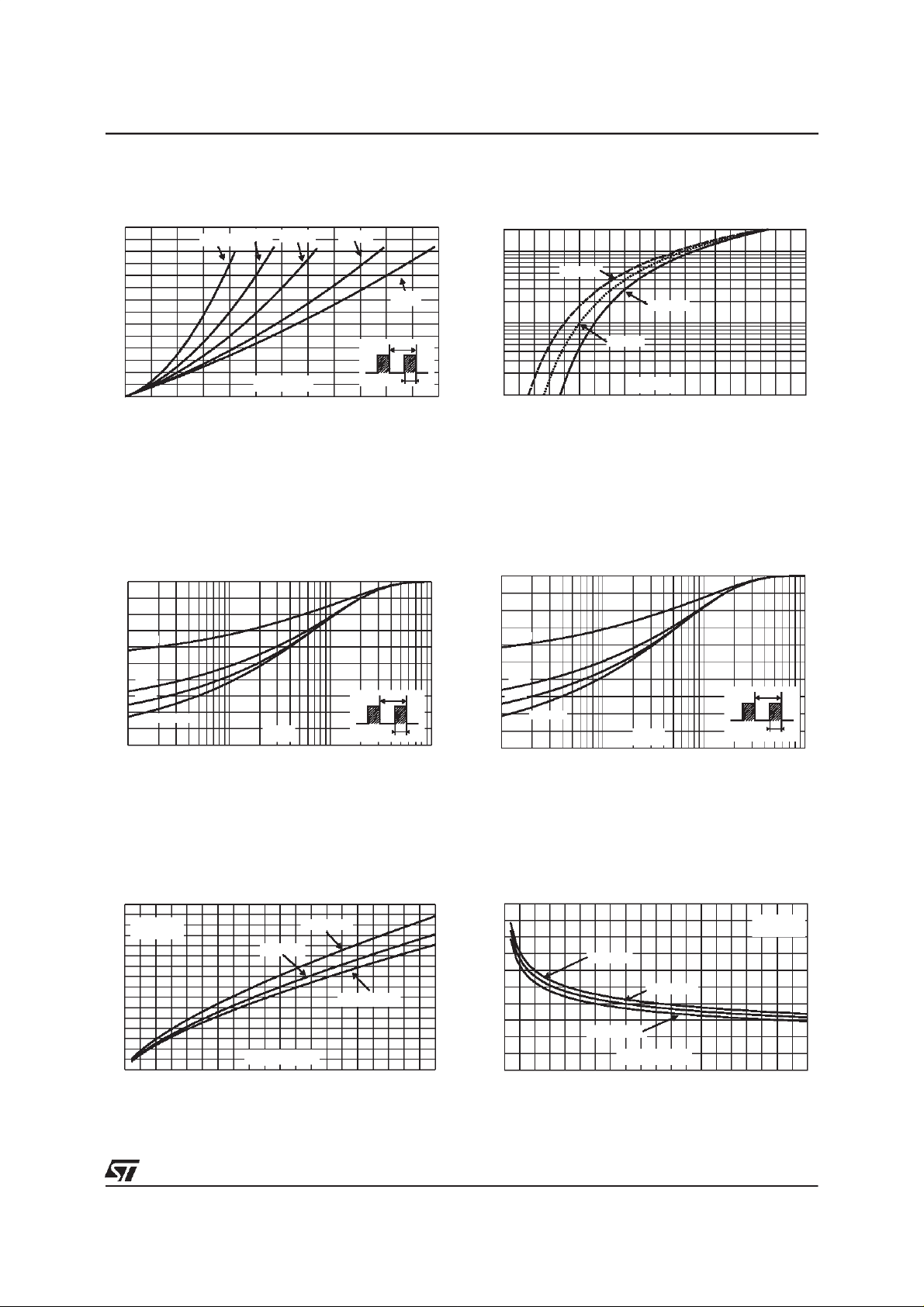
Fig.1:
Conductionlosses versus averagecurrent
(perdiode).
P1(W)
14
δ = 0.05
δ = 0.1
δ = 0.2
δ= 0.5
12
10
8
δ =1
6
4
2
0
024681012
IF(av)(A)
T
=tp/T tp
δ
Fig. 3-1: Relative variation of thermal impedance
junctionto case versus pulse duration (TO-220AB
2
.
PAK)
/D
Zth(j-c)/Rth(j-c)
1.0
Fig. 2:
Forward voltage drop versus forward
current(maximum values,perdiode).
IFM(A)
200
100
Tj=125°C
Tj=25°C
10
Tj=75°C
1
0.50 0.75 1.00 1.25 1.50 1.75 2.00 2.25 2.50 2.75 3.00
VFM(V)
Fig. 3-2: Relative variation of thermal impedance
junction to case versus pulse duration
(ISOWATT220AB).
Zth(j-c)/Rth(j-c)
1.0
0.8
δ = 0.5
0.6
δ = 0.2
0.4
δ = 0.1
0.2
0.0
Fig. 4:
dI
Single pulse
tp(s)
1E-3 1E-2 1E-1 1E+0
Peak reverse recovery current versus
/dt(90%confidence,per diode).
F
δ
=tp/T
T
tp
IRM(A)
16
14
12
VR=200V
Tj=125°C
IF=2*IF(av)
IF=IF(av)
10
8
6
IF=0.5*IF(av)
4
2
0
0 50 100 150 200 250 300 350 400 450 500
dIF/dt(A/µs)
0.8
δ= 0.5
0.6
δ= 0.2
0.4
δ = 0.1
0.2
0.0
Fig. 5:
Single pulse
tp(s)
1E-2 1E-1 1E+0 1E+1
Reverserecovery time versusdI
δ
=tp/T
F
T
tp
/dt (90%
confidence,per diode).
trr(ns)
100
80
60
IF=IF(av)
IF=2*IF(av)
40
20
IF=0.5*IF(av)
dIF/dt(A/µs)
0
0 50 100 150 200 250 300 350 400 450 500
VR=200V
Tj=125°C
3/7
Page 4

STTH2003CT/CG/CF
Fig.6: Softnessfactor (tb/ta)versusdIF/dt(typical
values,perdiode).
S factor
0.60
VR=200V
0.50
0.40
0.30
0.20
0.10
0.00
0 50 100 150 200 250 300 350 400 450 500
dIF/dt(A/µs)
Tj=125°C
Fig. 8: Transient peak forward voltage versus
dI
/dt (90%confidence,perdiode) (TO-220AB).
F
VFP(V)
10
IF=IF(av)
Tj=125°C
8
6
Fig. 7:
Relative variation of dynamic parameters
versusjunctiontemperature(reference:Tj=125°C).
2.4
2.2
2.0
1.8
1.6
1.4
1.2
1.0
0.8
0.6
0.4
0.2
0.0
25 50 75 100 125
Fig. 9:
Forward recoverytime versus dI
S factor
IRM
Tj(°C)
/dt (90%
F
confidence,per diode).
tfr(ns)
500
VFR=1.1*VF max.
400
300
IF=IF(av)
Tj=125°C
4
2
0
0 50 100 150 200 250 300 350 400 450 500
Fig. 10:
Thermal resistance junction to ambient
dIF/dt(A/µs)
versus copper surface under tab (Epoxy printed
circuit board FR4, copper thickness: 35µm)
2
PAK)
(D
Rth(j-a) (°C/W)
80
70
60
50
40
30
20
10
0
0 5 10 15 20 25 30 35 40
S(Cu) (cm )
200
100
dIF/dt(A/µs)
0
0 50 100 150 200 250 300 350 400 450 500
4/7
Page 5

PACKAGEMECHANICAL DATA
2
PAK
D
STTH2003CT/CG/CF
DIMENSIONS
L2
A
E
C2
REF.
A 4.40 4.60 0.173 0.181
Millimeters Inches
Min. Max. Min. Max.
A1 2.49 2.69 0.098 0.106
D
L
L3
A1
B2
B
C
R
A2 0.03 0.23 0.001 0.009
B 0.70 0.93 0.027 0.037
B2 1.14 1.70 0.045 0.067
C 0.45 0.60 0.017 0.024
C2 1.23 1.36 0.048 0.054
D 8.95 9.35 0.352 0.368
E 10.00 10.40 0.393 0.409
G
A2
G 4.88 5.28 0.192 0.208
L 15.00 15.85 0.590 0.624
L2 1.27 1.40 0.050 0.055
M
*
* FLATZONE NO LESSTHAN2mm
V2
L3 1.40 1.75 0.055 0.069
M 2.40 3.20 0.094 0.126
R 0.40 typ. 0.016 typ.
V2 0° 8° 0° 8°
FOOT PRINT DIMENSIONS
2
D
PAK
16.90
10.30
8.90
(in millimeters)
5.08
1.30
3.70
5/7
Page 6

STTH2003CT/CG/CF
PACKAGEMECHANICAL DATA
ISOWATT220AB
DIMENSIONS
REF.
Millimeters Inches
Min. Max. Min. Max.
A 4.40 4.60 0.173 0.181
B 2.50 2.70 0.098 0.106
D 2.50 2.75 0.098 0.108
E 0.40 0.70 0.016 0.028
F 0.75 1.00 0.030 0.039
F1 1.15 1.70 0.045 0.067
F2 1.15 1.70 0.045 0.067
G 4.95 5.20 0.195 0.205
G1 2.40 2.70 0.094 0.106
H 10.00 10.40 0.394 0.409
L2 16.00typ. 0.630typ.
L3 28.60 30.60 1.125 1.205
L4 9.80 10.60 0.386 0.417
L6 15.90 16.40 0.626 0.646
L7 9.00 9.30 0.354 0.366
Diam 3.00 3.20 0.118 0.126
6/7
Page 7

PACKAGEMECHANICAL DATA
TO-220AB
H2
Dia
L5
L6
L2
F2
F1
F
G1
G
L9
L4
STTH2003CT/CG/CF
DIMENSIONS
REF.
A
C
A 4.40 4.60 0.173 0.181
C 1.23 1.32 0.048 0.051
L7
D 2.40 2.72 0.094 0.107
E 0.49 0.70 0.019 0.027
F 0.61 0.88 0.024 0.034
F1 1.14 1.70 0.044 0.066
F2 1.14 1.70 0.044 0.066
G 4.95 5.15 0.194 0.202
D
G1 2.40 2.70 0.094 0.106
H2 10 10.40 0.393 0.409
L2 16.4 typ. 0.645typ.
L4 13 14 0.511 0.551
L5 2.65 2.95 0.104 0.116
M
E
L6 15.25 15.75 0.600 0.620
L7 6.20 6.60 0.244 0.259
L9 3.50 3.93 0.137 0.154
M 2.6 typ. 0.102typ.
Diam. 3.75 3.85 0.147 0.151
Millimeters Inches
Min. Max. Min. Max.
Orderingcode Marking Package Weight Base qty
Delivery
mode
STTH2003CT STTH2003CT TO-220AB 2.2 g. 50 Tube
2
STTH2003CG STTH2003CG D
PAK 1.48 g. 50 Tube
STTH2003CG-TR STTH2003CG D2PAK 1.48 g. 500 Tape&reel
STTH2003CF STTH2003CF ISOWATT220AB 2.08 g. 50 Tube
Coolingmethod:by conduction(C)
Recommendedtorquevalue:0.55N.m.
Maximumtorque value: 0.70N.m.
Epoxymeets UL 94,V0
Informationfurnished is believedto beaccurate andreliable. However,STMicroelectronics assumes no responsibilityfor the consequences of
use ofsuch informationnor forany infringementof patentsor otherrights ofthirdparties which mayresult fromits use.No license isgrantedby
implication or otherwise under any patent or patent rights of STMicroelectronics. Specifications mentioned in this publication are subject to
change without notice. Thispublication supersedes andreplaces all informationpreviously supplied.
STMicroelectronics products are not authorized for use as critical components in life support devices or systems without express written approval ofSTMicroelectronics.
The ST logo is a registered trademark of STMicroelectronics
1999 STMicroelectronics- Printed inItaly - All rights reserved.
STMicroelectronics GROUP OF COMPANIES
Australia -Brazil - China - Finland - France - Germany - Hong Kong - India - Italy - Japan - Malaysia
Malta - Morocco - Singapore - Spain - Sweden - Switzerland - United Kingdom - U.S.A.
http://www.st.com
7/7
 Loading...