


CybTouch 8
Rue des Uttins 27 CH-1401 Yverdon Switzerland TEL:+ 41 24 447 02 00 FAX:+ 41 24 447 02 01 E-Mail: info@cybelec.ch
CybTouch8_PS_812io_V2.1.doc / November 2013 Page 1 of 10
Input/Output List for CybTouch 8 (8/12io SBC-200A)
For all CybTouch SN xxxxxx/A1 and above
i
M4x6 m ax.
X7
1
12
X1
0V24V
X2
1
4
7
8
11
14
X3
1
4
7
8
11
14
X4
1
4
7
8
11
14
X5
1
4
7
8
11
14
X6
1
4
7
8
11
14
18
21
22
25
28
24Vi/o
0Vi/o
18
21
22
25
28
24Vi/o
0Vi/o
18
21
22
25
28
24Vi/o
0Vi/o
18
21
22
25
28
15
18
21
22
25
28
24Vi/o
0Vi/o
Encoders
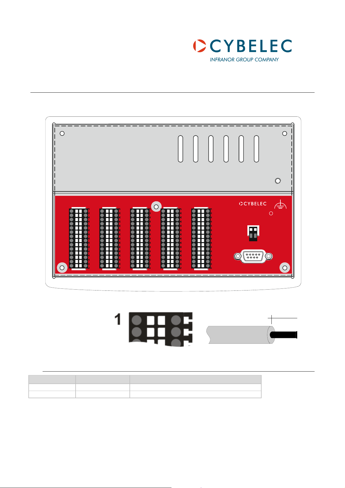
Connectors X2 to X5 =
Weidmüller
B2L 3.5/28/180
SN BK
L Max 4 A / connector pin.
max 8 m
m
0.75 mm
2
X1 Power Connector
X1 Signal Default I/0
1 24 V 24 VDC DNC
2 0V 0V DNC

CybTouch8_PS_812io_V2.1.doc Page 2 of 10
Generalities
• All 0V_I/O pins are connected together.
• The 24V_I/O pins from connectors X2 and X3 are connected together.
• The 24V_I/O pins from connectors X4 and X6 are connected together
• All digital outputs are capable of driving a load (for example valves) up to 3 A maximum.
Digital outputs are short-circuit and overload protected.
• Inductive loads must be equipped with surge suppressors.
• See basic diagram.
CybTouch8_PS_812io_V2.1.doc Page 3 of 10
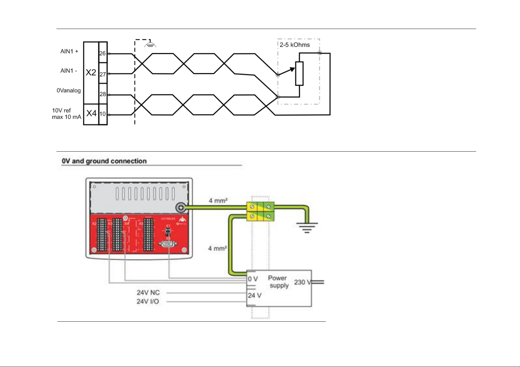
Crowning Wiring
Earth and 24 VDC Wiring
A 4 wires shielded cable must
be used for the potentiometer.
X2/27and X2/28 terminals
must be connected together
at one side of the potentiometer.
The cable shield must be connected to the
chassis of the CybTouch using the grounding
system.
If a twisted pair cable is used, use twisted pair
shown.
 Loading...