


 Loading...
CybTouch 6 P
Press Brake
Machine Parameters Manual V.2.0
Page left blank intentionally

v2.0 |
Nov.12 |
|
|
TABLE OF CONTENTS |
P01 MACHINE CONFIGURATION......................................................................................................... |
6 |
|
Menu Button......................................................................................................................................... |
6 |
|
Toggle Pages Button ........................................................................................................................... |
6 |
|
P01.01 |
Machine Type .......................................................................................................................... |
7 |
P01.02 Punch & Die Management ...................................................................................................... |
7 |
|
P01.03 |
Start Pump Button ................................................................................................................... |
7 |
P01.04 |
Quantity ................................................................................................................................... |
8 |
P01.05 |
Material.................................................................................................................................... |
8 |
P01.06 |
Retraction ................................................................................................................................ |
8 |
P01.07 |
Bending Length ....................................................................................................................... |
8 |
P01.08 |
TDC Return ............................................................................................................................. |
8 |
P01.09 |
Bending Force ......................................................................................................................... |
9 |
P01.10 |
Dwell Time............................................................................................................................... |
9 |
P01.11 |
Crowning ................................................................................................................................. |
9 |
P01.12 |
X Axis ...................................................................................................................................... |
9 |
P01.13 |
Y Axis ...................................................................................................................................... |
9 |
P02 MACHINE CONFIGURATION 2.................................................................................................... |
10 |
|
P02.01 |
Auxilary Function ................................................................................................................... |
10 |
P02.02 Eco Mode .............................................................................................................................. |
10 |
|
P02.03 |
Store/Delete Programs in Level 0 ......................................................................................... |
10 |
P02.04 |
Level 0 Lock HMI................................................................................................................... |
11 |
P02.05 |
Toggle Pages ........................................................................................................................ |
11 |
P02.06 |
Show Cycle Steps ................................................................................................................. |
11 |
P02.07 |
Show Button Up..................................................................................................................... |
11 |
P03 PREFERENCES ............................................................................................................................ |
12 |
|
P03.01 |
Square Signal Low/High........................................................................................................ |
12 |
P03.02 |
Axes Start At.......................................................................................................................... |
12 |
P03.03 |
Y axis Delay........................................................................................................................... |
12 |
P04 AXIS SETTINGS............................................................................................................................ |
13 |
|
P04.00 |
Display Resolution................................................................................................................. |
13 |
P04.01 |
Axis Type............................................................................................................................... |
13 |
P04.02 |
Closed Loop .......................................................................................................................... |
13 |
P04.03 |
Encoder Resolution ............................................................................................................... |
14 |
P04.04 |
Position Speed ...................................................................................................................... |
14 |
P04.05 |
Position Tolerance................................................................................................................. |
14 |
P04.06 |
One-Way Positioning............................................................................................................. |
14 |
Advanced button ................................................................................................................................ |
15 |
|
PM_CybTouch6_ PressBrakes_v2.0.doc |
page 3 of 43 |
v2.0 |
Nov. 12 |
Axis Settings -X- Wizard .................................................................................................................... |
15 |
|
P04B ADVANCED AXIS REGULATOR –X- ........................................................................................ |
18 |
|
P04b.01 Change Counting Direction ................................................................................................. |
18 |
|
P04b.02 Manual Speed ..................................................................................................................... |
18 |
|
P04b.03 Acceleration......................................................................................................................... |
18 |
|
P04b.04 Invert voltage & Speed at 10V............................................................................................. |
18 |
|
P04b.05 Closed Loop Frequency ...................................................................................................... |
18 |
|
P04b.06 Integrator factor ................................................................................................................... |
19 |
|
P04b.07 Offset Voltage...................................................................................................................... |
19 |
|
P04b.08 Supervisor Error .................................................................................................................. |
19 |
|
P04b.09 Supervisor Speed Level ...................................................................................................... |
19 |
|
P04b.10 Control Time Out ................................................................................................................. |
19 |
|
05 INDEXATION AXIS -X- .................................................................................................................... |
20 |
|
Indexation Axis -X- wizard ................................................................................................................. |
20 |
|
P05.01 |
Index Type............................................................................................................................. |
20 |
P05.02 |
Index Zone: Reverse Logic ................................................................................................... |
20 |
P05.03 |
Start Indexation in Negative Direction ................................................................................... |
20 |
P05.04 |
Indexation Speed................................................................................................................... |
21 |
P05.05 |
Index Position ........................................................................................................................ |
21 |
P05.06 |
Minimum Limit ....................................................................................................................... |
21 |
P05.07 |
Maximum Limit ...................................................................................................................... |
21 |
06 AXIS FUNCTIONS -X- ..................................................................................................................... |
22 |
|
P06.01 |
Speed with Input “Speed Reduction”..................................................................................... |
22 |
07 DIGITAL INPUT CONFIGURATION¨............................................................................................... |
23 |
|
08 DIGITAL OUTPUT CONFIGURATION............................................................................................ |
25 |
|
09 ANALOG I/O CONFIGURATION..................................................................................................... |
27 |
|
10 PRESSURE...................................................................................................................................... |
28 |
|
P10.01 Max Tonnage......................................................................................................................... |
28 |
|
P10.02 |
Min Tonnage.......................................................................................................................... |
28 |
P10.03 |
HS Down Pressure ................................................................................................................ |
28 |
P10.04 |
LS Down Pressure................................................................................................................. |
28 |
P10.05 |
Up Pressure........................................................................................................................... |
28 |
P10.06 |
Decompression Pressure ...................................................................................................... |
29 |
P10.07 |
Decompression Time min/max.............................................................................................. |
29 |
P10.08 |
Acceleration/Deceleration Time ............................................................................................ |
29 |
11 CROWNING ..................................................................................................................................... |
30 |
|
Voltage Crowning............................................................................................................................... |
30 |
|
Analog Crowning................................................................................................................................ |
30 |
|
Crowning Wizard................................................................................................................................ |
31 |
|
P11.01 |
Inverted AD Input (only crowning analog) ............................................................................. |
31 |
PM_CybTouch6_ PressBrakes_v2.0.doc |
page 4 of 43 |
v2.0 |
Nov. 12 |
P11.02 |
Tolerance............................................................................................................................... |
31 |
P11.03 |
Advanced Stop ...................................................................................................................... |
31 |
P11.04 |
Overrun Distance................................................................................................................... |
31 |
P11.05 SN/SN Time........................................................................................................................... |
31 |
|
12 BEAM 1 (ONLY WITH FOOTSWITCH) ........................................................................................... |
32 |
|
P12.01 Low Speed............................................................................................................................. |
32 |
|
P12.02 |
Min Bending Time.................................................................................................................. |
32 |
P12.03 |
Default BDC........................................................................................................................... |
32 |
13 BEAM 2 (ONLY WITH FOOTSWITCH) ........................................................................................... |
33 |
|
P13.01 |
Machine Correction T1 T2..................................................................................................... |
33 |
Time Switch point – Pinch point (T1) ................................................................................................. |
33 |
|
P14 BEAM (PL MODE ONLY).............................................................................................................. |
34 |
|
P14.01 |
Change Counting Direction ................................................................................................... |
34 |
P14.02 |
Encoder Resolution ............................................................................................................... |
34 |
P14.04 |
Final Approach Distance ....................................................................................................... |
34 |
P14.05 |
Speed for Beam Stop Detection............................................................................................ |
34 |
P14.06 |
Pinch Point Advanced Stop................................................................................................... |
34 |
P14.07 BDC Advanced Stop ............................................................................................................. |
34 |
|
P14.08 |
Index Position ........................................................................................................................ |
34 |
P14.09 |
Minimum Limit ....................................................................................................................... |
35 |
P14.10 |
Maximum Limit ...................................................................................................................... |
35 |
P15 VALVES CONTROL ...................................................................................................................... |
36 |
|
CHANGING ACCESS LEVEL SECURITY PASSWORDS .................................................................. |
37 |
|
Default Passwords ............................................................................................................................. |
37 |
|
Changing Passwords ......................................................................................................................... |
37 |
|
CREATING BACKUPS AND RESTORING DATA............................................................................... |
39 |
|
Creating an Internal Backup of Machine Parameters........................................................................ |
39 |
|
Restoring Creating an Internal Backup of Machine Parameters ....................................................... |
39 |
|
ERROR AND WARNING MESSAGES IN CYBTOUCH 6 FOR PRESS-BRAKES ............................. |
40 |
|
PM_CybTouch6_ PressBrakes_v2.0.doc |
page 5 of 43 |
v2.0 |
Nov. 12 |
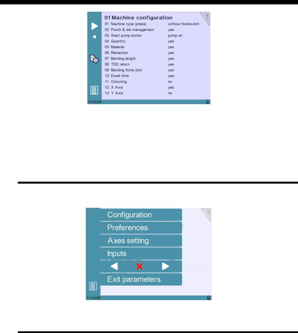
P01 MACHINE CONFIGURATION
This manual explains the functionalities of the CybTouch 6 for conventional presses, independently of the limits imposed by the hardware and the subsequent available inputs and outputs.
This manual describes all features of CybTouch 6 P software version 2.0.0
Menu Button
The Menu button  will allow you to exit the machine configuration page or to scroll through the machine parameters pages:
Toggle Pages Button
The Toggle pages button  is described in section P02.05 Toggle Pages.
PM_CybTouch6_ PressBrakes_v2.0.doc |
page 6 of 43 |
v2.0 |
Nov. 12 |
P01.01 Machine Type
 Without footswitch: CybTouch doesn’t receive the footswitch information. It acts as a positioning control. A Machine Ready output informs the electrical box that the axes are in position. The cycle of the machine is fully managed by the electrical box.
 With footswitch: CybTouch receives the footswitch information. The CybTouch gives the electrical box orders for the beam to move down and up (safety must be ensured in the electrical box). This mode simplifies the electrical box diagram. It also allows the use of timers for beam travel, as well a valve control feature that allows the valves to be configured as needed.
 PL type: Machine type is PL. This kind of machine uses on-off valves to move the beam and stop the beam atBDC. A linear encoder must be mounted on the beam.
P01.02 Punch & Die Management
Set this parameter to Yes to make punch and die management available on the CybTouch. This also allows the operator to program angle and L with bend allowance. Set the parameter to No to work without tool management.
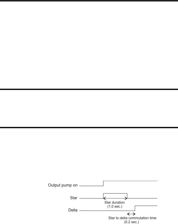
P01.03 Start Pump Button
Touch the Start Pump field to select:
 No = Start Pump button is not available on screen.
 Yes = Start Pump button is available on screen.
1 output (Pump_on) is dedicated to this.
 Pump star delta button is available on screen.
3 outputs are dedicated to the star delta pump start. 1.0s = star duration
0.2s = star to delta commutation time
PM_CybTouch6_ PressBrakes_v2.0.doc |
page 7 of 43 |

v2.0 |
Nov. 12 |
P01.04 Quantity
The Show quantity function can be enabled or not.
This function allows the operator to enter a number of times a program can be repeated (number of pieces to be produced).
 No: The quantity counter is not displayed.
 Yes: The quantity counter is displayed; the operator can enter a number of pieces to be produced.
P01.05 Material
The Material function can be enabled or not:
 No: Material selection is not displayed.
 Yes: Material selection is displayed; the operator can select the material type.
P01.06 Retraction
Set this parameter to No to hide the back-gauge retraction function  in the Bend More
  page available.
P01.07 Bending Length
Set this parameter to Yes to make the bending length calculation  in the Bend
More  page available or No to hide it.
If available, when the operator enters the bending length, the CybTouch automatically calculates the necessary pressure (tools management must be set to yes).
If tool management is set to No, the CybTouch is not able to calculate the tonnage. The bending length may still available for the operator as bending information only. The operator will have to program pressure manually.
P01.08 TDC Return
Set this parameter to Yes to make the opening distance  in the Bend
More  page available, or No to hide it.
If set to Yes, after the decompression the output Return to TDC is active for the programmed time. This output will activate the up movement of the beam and allow the operator to adjust the opening depending on their needs.
PM_CybTouch6_ PressBrakes_v2.0.doc |
page 8 of 43 |

v2.0 |
Nov. 12 |
P01.09 Bending Force
Set this parameter to Yes to make the bending force  in the Bend More
  page available, or No to hide it.
If available, the operator may enter another bending force as the calculated one. To calculate the pressure, tools management must be set to yes.
P01.10 Dwell Time
Set this parameter to Yes to make the dwell time function  in the Bend More
  page available, or No to hide it.
P01.11 Crowning
Set this parameter to Yes to make the crowning function  in the Bend More
  page available or No to hide it.
When available, crowning can be set as voltage or analog.
Voltage is used to drive a proportional (pressure) crowning valve. Associated to this mode is the analog output Crowing, available in 3.13 when the default configuration is set. This analog output (0-10VDC) will be used to drive the crowning pressure amplifier.
Analog is used for mechanical crowning with potentiometer feedback. Associated to this mode is one Crowning analog input and 2 digital Crowning SP and SN outputs, available when the default configuration is set.
P01.12 X Axis
Select whether to configure a X axis or not. Can be temporarily deselected if the backgauge is not yet mounted on the machine, in order to test the beam functions.
P01.13 Y Axis
Select whether to configure a Y axis or not. Same as above
PM_CybTouch6_ PressBrakes_v2.0.doc |
page 9 of 43 |
v2.0 |
Nov. 12 |
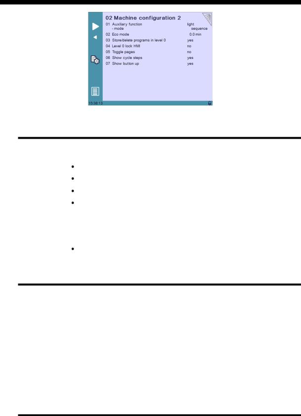
P02 MACHINE CONFIGURATION 2
P02.01 Auxilary Function
A preset auxiliary function can be configured (light) and one or two freely configurable auxiliary functions can be added: F1 or F1+F2.
None: No auxiliary function configured.
Light: Light is configured.
F1: 1 auxiliary function is configured and called F1.
F1+F2: 2 auxiliary functions are configured, called F1 and F2, and can be used separately or at the same time.
When auxiliary functions are configured, the below parameter determines if they are to be applied to the whole machine (on-off on operator use), saved in the complete program for a specific part, or saved in a sequence in a part.
mode: machine/part/sequence.
P02.02 Eco Mode
The Eco mode parameter defines after how much time of operator or machine inactivity the CybTouch will switch to economical mode.
When switching into Eco mode the Pump on output is turned off and the screen becomes darker.
Current value is usually 5-15 min.
Setting the Eco Mode to 0.0 min deactivates Eco mode.
Note: If the Start Pump button is not configured on the screen, but wired conventionally, the Eco mode off output can be used to switch off the pump after the Eco mode time is reached. Please refer to basic electrical diagrams.
P02.03 Store/Delete Programs in Level 0
Here you can choose whether or not operators with access level 0 can be authorized to store or delete programs in the CybTouch.
PM_CybTouch6_ PressBrakes_v2.0.doc |
page 10 of 43 |
v2.0 |
Nov. 12 |
P02.04 Level 0 Lock HMI
The Human-Machine Interface can be locked in level 0. This is commonly used when machines are left unattended on exhibitions to prevent visitors from changing programs.
When set to Yes, the operator will need a code to access programming (level 2).
The HMI will be automatically locked every time:
 The CybTouch is switched off.
 After CybTouch switches to Eco mode.
 The HMI can be locked manually when you open the menu and press the padlock
  icon.
icon.
The unlocking code is “55".
(see section Changing Access Level Security Passwords for more details).
P02.05 Toggle Pages
If activated, the toggle button  allows you to switch directly from any parameter page "back" to the last working page visited before accessing the parameters.
Once you are in the working pages, touching  allows you to return to the last accessed parameter page.
This functionality is very useful for technicians during the machine set-up.
Its vivid orange color just informs the technician that this toggle page mode is active and acts as a reminder to deactivate this functionality before machine delivery.
The Toggle pages button will disappear automatically from operator pages (Toggle page parameter set to no) after 24 hours of inactivity.
P02.06 Show Cycle Steps
Cycle steps messages at the top of the screen can be displayed or not by activating or deactivating the Show Cycle Steps parameter.
Ex: .
.
By default this parameter is set to Yes. The operator immediately knows in which phase the machine currently is. This feature and the Machine Status pages are very helpful during the first service calls between the operator and the service engineer.
P02.07 Show Button Up
Select Yes to display the Up  button. Select No to hide it.
Pressing this button will activate the output Return to TDC until the machine switch (input TDC) is reached or the button Up  released.
PM_CybTouch6_ PressBrakes_v2.0.doc |
page 11 of 43 |
v2.0 |
Nov. 12 |
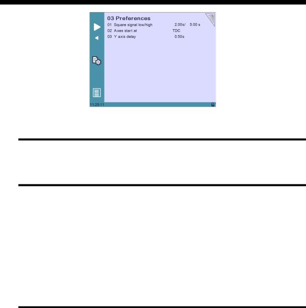
P03 PREFERENCES
P03.01 Square Signal Low/High
The square signal is used to carry out tests on the machine.
P03.02 Axes Start At
The axes (back gauge) can be configured to start positioning at different moments, depending on the position of the beam:
 BDC if X SP:
o If the axes movement will be in positive direction, axes (back gauge) will start once the beam reaches BDC.
o If the axes movement will be in negative direction, axes (back gauge) will wait and start once the beam reaches TDC.
 BDC: Axes start moving after beam decompression (at BDC).
 TDC: Axes start moving when beam reaches TDC.
P03.03 Y axis Delay
This parameter determines the time after which the Y axis begins to move up after decompression.
PM_CybTouch6_ PressBrakes_v2.0.doc |
page 12 of 43 |
v2.0 |
Nov. 12 |
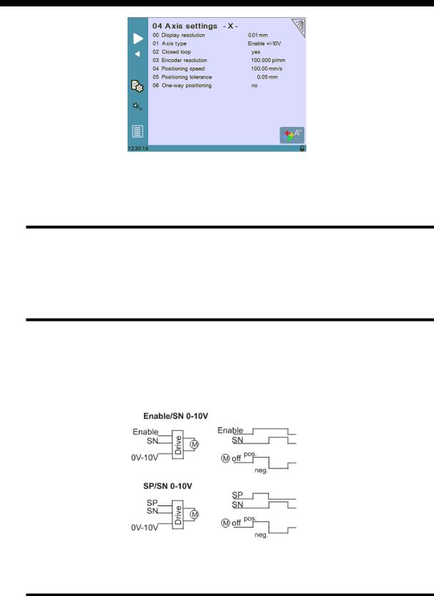
P04 AXIS SETTINGS
Simply touch the –X– or –Y– in the page title to switch from one axis page to the other.
P04.00 Display Resolution
This value must be entered manually before using the Wizard.
Here you must set the displayed resolution for the selected axis to 0.01 mm,
0.1 mm or 1 mm.
P04.01 Axis Type
This value must be entered manually before using the Wizard.
Depending on the drive logic, you must select either:
For AC brushless motor, select Enable +/-10V.
For frequency converter with asynchronous motor , select either En/SN 0/10V, or SP/SN 0/10V:
P04.02 Closed Loop
Must be set manually before using the Wizard.
If you are using a frequency converter this parameter must be set to No.
PM_CybTouch6_ PressBrakes_v2.0.doc |
page 13 of 43 |
Loading...