


 Loading...
CybTouch 6 G-W
Shears
Machine Parameters Manual V.2.0
Page left blank intentionally

v2.0 |
Nov.12 |
|
TABLE OF CONTENTS |
|
INTRODUCTION ..................................................................................................................................... |
6 |
|
P01 MACHINE CONFIGURATION......................................................................................................... |
7 |
|
Menu Button |
7 |
|
Toggle Pages Button |
7 |
|
P01.01 |
Machine Type |
7 |
P01.02 |
Start Pump Button |
8 |
P01.03 |
Automatic Cut |
8 |
P01.04 |
Quantity |
8 |
P01.05 |
Material |
9 |
P01.06 |
Blade Gap |
9 |
P01.07 |
Second Blade Gap |
9 |
P01.08 |
Axis |
10 |
P02 MACHINE CONFIGURATION 2...................................................................................................... |
11 |
|
P02.01 |
Sheet Support |
11 |
P02.02 |
Return to Sender (RTS) |
12 |
P03 MACHINE CONFIGURATION 3...................................................................................................... |
13 |
|
P03.01 |
Auxilary Function |
13 |
P03.02 Eco Mode |
13 |
|
P03.03 |
Store/Delete Programs in Level 0 |
14 |
P03.04 |
HMI Locked in Level 0 |
14 |
P03.05 |
Toggle Pages |
14 |
P03.06 |
Show Cycle Steps |
14 |
P03.07 |
Retraction |
15 |
P03.08 |
Analog Pressure |
15 |
P03.09 |
Cutting Length Sensor |
15 |
P04 MACHINE SETTINGS ..................................................................................................................... |
16 |
|
Machine Settings Wizard |
16 |
|
P04.01 |
Max Programmable Cutting Length |
16 |
P04.02 |
Time Before Axis Start at BDC |
16 |
P04.03 |
Default Time for Max Cutting Length |
17 |
P04.04 |
Time to Close Hold-Downs |
17 |
P04.05 |
Time to Close Hold-Downs if not TDC max |
17 |
P04.06 |
Timing Valves |
18 |
P04.07 |
AutoCut Minimum Waiting Time at TDC |
18 |
P05 PREFERENCES .............................................................................................................................. |
19 |
|
P05.01 |
Axes Start at |
19 |
P05.02 |
Sheet Offset |
19 |
PM_CybTouch6_ Shears_v2.0.doc |
page 3 of 55 |
v2.0 |
Nov.12 |
P05.03 |
Angle Control at TDC Max |
19 |
P05.04 |
Square Signal Low/High |
19 |
P06 AXIS SETTINGS -X- ........................................................................................................................ |
20 |
|
P06.00 |
Display Resolution |
20 |
P06.01 |
Axis Type |
20 |
P06.02 |
Closed Loop |
20 |
P06.03 |
Encoder resolution |
21 |
P06.04 |
Position Speed |
21 |
P06.05 |
Position Tolerance |
21 |
P06.06 |
One-Way Positioning |
21 |
Advanced button |
22 |
|
Axis Settings -X- Wizard |
22 |
|
P06B ADVANCED AXIS REGULATOR X ............................................................................................. |
25 |
|
P06b.01 Change Counting Direction |
25 |
|
P06b.02 Manual Speed |
25 |
|
P06b.03 Acceleration |
25 |
|
P06b.04 Invert voltage & Speed at 10V |
25 |
|
P06b.05 Closed Loop Frequency |
25 |
|
P06b.06 Integrator factor |
26 |
|
P06b.07 Offset Voltage |
26 |
|
P06b.08 Supervisor Error |
26 |
|
P06b.09 Supervisor Speed Level |
26 |
|
P06b.10 Control Time Out |
27 |
|
07 INDEXATION AXIS -X- ...................................................................................................................... |
28 |
|
Indexation Axis -X- Wizard |
28 |
|
P07.01 |
Index Type |
29 |
P07.02 |
Index Zone in Reverse Logic |
29 |
P07.03 |
Start Indexation in Negative Direction |
29 |
P07.04 |
Indexation Speed |
29 |
P07.05 |
Index Position |
29 |
P07.06 |
Minimum Limit |
29 |
P07.07 |
Maximum Limit |
30 |
P07.10 |
Parking |
30 |
P07.11 |
Parking Tolerance |
30 |
08 AXIS FUNCTIONS -X- ....................................................................................................................... |
31 |
|
P08.01 |
Blade Gap Factor |
32 |
P08.02 |
Speed with input “Speed reduction” |
32 |
P09 DIGITAL INPUT CONFIGURATION ............................................................................................... |
33 |
|
P10 DIGITAL OUTPUT CONFIGURATION ........................................................................................... |
35 |
|
P11 ANALOG I/O CONFIGURATION .................................................................................................... |
37 |
|
PM_CybTouch6_ Shears_v2.0.doc |
page 4 of 55 |
v2.0 |
Nov.12 |
P12 BLADE GAP .................................................................................................................................... |
38 |
|
Blade Gap Wizard |
38 |
|
P12.01 |
Inverted AD Input |
39 |
P12.02 |
Tolerance |
39 |
P12.03 |
Advanced Stop |
39 |
P12.04 |
Overrun Distance |
39 |
P12.05 SP/SN Time |
39 |
|
P13 ANGLE & CUTTING LENGTH ........................................................................................................ |
40 |
|
Angle & Cutting Length Wizard |
40 |
|
P14 ANGLE AND CUTTING LENGTH 2................................................................................................ |
41 |
|
P14.01 |
Inverted Input |
41 |
P14.02 |
Resolution |
41 |
P14.03 |
Minimum Limit |
41 |
P 14.04 Distance Max TDC – Mechanical Stop |
41 |
|
P14.05 |
TDC Time Before Angle Control |
41 |
P14.06 |
Cutting Angle Tolerance |
42 |
P14.07 |
Stop if Angle Sensor Max |
42 |
P14.08 |
Advanced stop, angle down/up |
42 |
P14.09 |
Advanced stop, cut down/up |
42 |
P15 PRESSURE ..................................................................................................................................... |
43 |
|
Pressure Wizard |
43 |
|
P15.02 Minimum Pressure Beam Down |
43 |
|
P15.03 Beam Up |
44 |
|
P15.04 |
Final Approach Up (min pressure) |
44 |
P15.05 |
Ramp / Final Approach Up |
44 |
P15.06 |
Final Approach Speed Up |
44 |
P15.07 |
Final Approach Gain |
44 |
P15.08 |
Cutting Angle |
44 |
P15.09 |
Blade Gap |
44 |
P15.10 |
Ramp Cutting Pressure |
44 |
CHANGING ACCESS LEVEL SECURITY PASSWORDS: ................................................................... |
45 |
|
Default passwords |
45 |
|
Changing passwords |
45 |
|
CREATING BACKUPS AND RESTORING DATA................................................................................. |
47 |
|
Creating an Internal Backup of Machine Parameters |
47 |
|
Restoring Creating an Internal Backup of Machine Parameters |
47 |
|
ERROR AND WARNING MESSAGES IN CYBTOUCH 6 FOR SHEARS............................................. |
48 |
|
APPENDIX 1 – USING REMOTE CONTROL ........................................................................................ |
54 |
|
Wiring Recommendation for Remote Control |
55 |
|
PM_CybTouch6_ Shears_v2.0.doc |
page 5 of 55 |

v2.0 |
Nov.12 |
INTRODUCTION
This manual is specifically written for qualified technicians.
Information contained herein will serve as a guide for all technicians setting up shear machines with the Cybelec CybTouch 6 numerical control.
The following documents may also be useful to a technician for setting up and testing a shear machine with the CybTouch 6:
CybTouch 6 for shears user manual:
CybTouch6_Shear_Usermanual_EN_vx.x.pdf
CybTouch 6 for shears technical manual:
CybTouch_6_G_1612io_Technical_manual_vx.x.pdf OR CybTouch_6_W_88io_Technical_manual_vx.x.pdf
The present manual will describe all machine parameters of the CybTouch.
Please note that modifications to the machine parameters may imply additional inputs or outputs to be configured (also done in the machine parameters), and will have a direct effect on the HMI. Functions and/or buttons will be deactivated/hidden/made available depending on the machine configuration.
This manual describes all features of CybTouch 6 X or G with software version 2.0.0.
PM_CybTouch6_ Shears_v2.0.doc |
page 6 of 55 |
v2.0 |
Nov.12 |
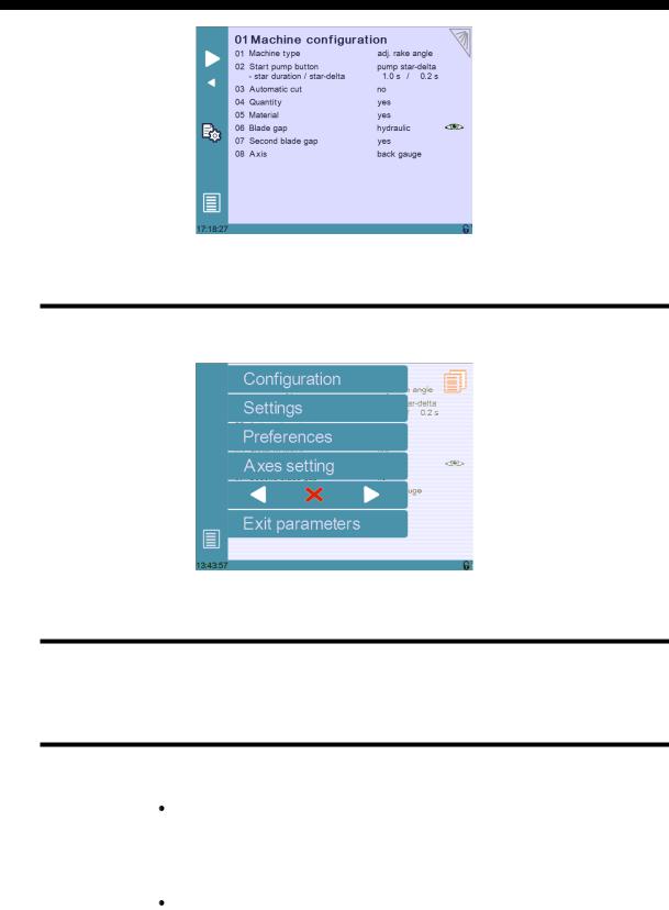
P01 MACHINE CONFIGURATION
Menu Button
The Menu button  allows you to exit the P01 Machine Configuration page or to scroll through the other machine parameters pages:
Toggle Pages Button
The Toggle pages button  is described in section P03.05 Toggle Pages.
P01.01 Machine Type
Touch the Machine type field to choose the type of machine used with the CybTouch:
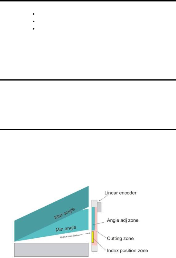
Adjustable rake angle: Select this mode if your machine has a rake angle managed by the CybTouch. Angle and cutting length are managed by a sensor (potentiometer or linear encoder).
Selecting this option will give you access to dedicated machine parameters for controlling this type of shears.
Swing: Select this mode if your machine has a fixed angle. The cutting length is managed by a timer.
PM_CybTouch6_ Shears_v2.0.doc |
page 7 of 55 |
v2.0 |
Nov.12 |
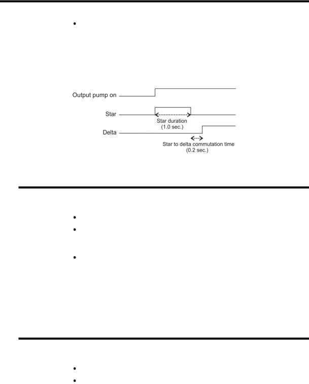
P01.02 Start Pump Button
Touch the Start Pump field to select:
No = Start Pump: start pump button is not available on screen.
 Yes = Start Pump start pump button is available on screen. 1 output (Pump_on) is dedicated to this.
 Pump star delta start pump button is available on screen. 3 outputs are dedicated to the star delta pump start.
1.0s = star duration.
0.2s = star to delta commutation time.
P01.03 Automatic Cut
The Automatic cut function is only available in EasyCut mode, and can be configured as follows:
No: The Automatic cut function is disabled.
Yes, auto stop: The Automatic cut function is enabled but will be deactivated when the operator releases the foot pedal. The operator then has to press the Automatic cut button again to work in AutoCut mode.
Yes, no auto stop: The Automatic cut function is enabled and will remain enabled, even after releasing the pedal. Usually, if this feature is configured a key switch is wired to the machine to allow (or not) the Automatic cut function.
Note: The Automatic cut input must be activated to enable the Automatic cut icon ( ) on the screen.
P01.04 Quantity
When enabled, the Show quantity function allows the operator to enter a number of times a program can be repeated (number of pieces to be produced).
No: The quantity counter is not displayed.
Yes: The quantity counter is displayed; the operator can enter a number of pieces to be produced.
PM_CybTouch6_ Shears_v2.0.doc |
page 8 of 55 |

v2.0 |
Nov.12 |
P01.05 Material
When enabled, the Show material function will display the material type used and allow the operator to change the material type:
Yes: Material selection is displayed; the operator can select the material type.
No: Material selection is not displayed. Blade gap is also not visible
- Minimum display Yes/No
When set to Yes, the working pages of the interface are simplified (less icons) so that the CybTouch can be used as a positioner control.
P01.06 Blade Gap
The blade gap is adjusted according to the selected material and thickness. These values are set in the Material page by the machine manufacturer. Usually the blade gap is not modified by the operator and is only shown to the operator.
Note: Blade gap feedback can only be provided by a potentiometer.
No: No blade gap management; blade gap icon and value are not displayed and cannot be configured in machine parameters.
Show only: Blade gap is not managed by the CybTouch (manual blade gap) but the blade gap values must be entered in Material page.
When the P01.05 Material is set to Show only, icon and value are displayed for reference only to the operator (P12 Blade gap page is hidden).
Electric or Hydraulic: choose the type of blade gap (electric motor or hydraulic cylinder). The icon and value are displayed and can be configured in machine parameters (P12 Blade gap page).
Note: When Hydraulic is selected, Pressure output must be configured.
 : Blade gap value is visible on work pages.
 : Blade gap value is not visible on work pages.
Note: If the operator needs to change the blade gap, it must be set as visible and the programmable tolerances must be set in the Material pages. See Materials section in CybTouch 6 user guide for more details.
P01.07 Second Blade Gap
A second blade gap can be configured. See P12 Blade gap page for calibration.
No: Only 1 blade gap actuator.
Yes: If a second blade gap is needed.
Note: Blade gap feedback can only be provided by a potentiometer.
PM_CybTouch6_ Shears_v2.0.doc |
page 9 of 55 |

v2.0 |
Nov.12 |
P01.08 Axis
Back gauge: The back gauge is configured and can be used.
Front gauge: The front gauge is configured and can be used. P01.09 Clamp parameter becomes available.
None: The back gauge is disabled (screen and management). This feature is commonly used at startup of the machine.
PM_CybTouch6_ Shears_v2.0.doc |
page 10 of 55 |
v2.0 |
Nov.12 |
P02 MACHINE CONFIGURATION 2
P02.01 Sheet Support
The sheet support cycle must be managed by the electrical box.
The sheet support function activates 1 output for Sheet support 2 (with 2 positions) or 2 outputs for Sheet support 3 (with 3 positions).
The sheet support can be configured as follows:
No: No sheet support.
Sheet support 2 pos: Sheet support with 2 positions (1 output).
Sheet support 3 pos: Sheet support with 3 positions (2 outputs).
Disable support in zone: E.g. 0.0 – 300.0 mm values are entered: for a part less than 300 mm in length, sheet support isn’t used.
Note: Once configured, the sheet support button is available in the work pages for the operator to select.
PM_CybTouch6_ Shears_v2.0.doc |
page 11 of 55 |

v2.0 |
Nov.12 |
P02.02 Return to Sender (RTS)
Sheet support must be configured to activate the RTS function. The RTS function can be configured as follows:
No: RTS is not configured.
o Warning: RTS is configured and operator will see a warning popup if max weight is exceeded. Operator can acknowledge the popup and continue by pressing the foot pedal.
oNot allowed: RTS not available if max weight, min X dist, or max X distance is exceeded.
RTS allowed in park position: RTS can be allowed or not when the gauge is in parking position.
Retraction distance: RTS mode back gauge retraction distance is usually greater than normal retraction.
Return speed: Speed at which the cut piece is pushed back to the sender by the back gauge. The return is triggered by touching the RTS button on the screen or using the RTS move input.
Min X dist: Minimum length of the part for which the RTS will be used, depending on the choice made above.
Max X dist: Maximum length of the part for which the RTS will be used, depending on the choice made above.
Max weight: Maximum weight of the part for using RTS function, depending on the choice made above.
PM_CybTouch6_ Shears_v2.0.doc |
page 12 of 55 |
v2.0 |
Nov.12 |
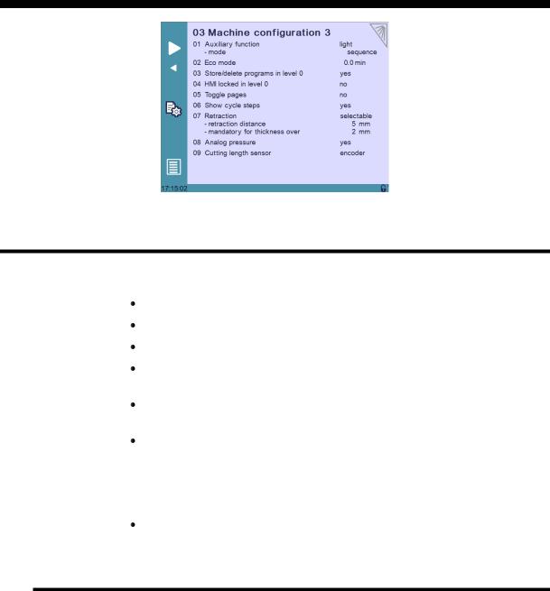
P03 MACHINE CONFIGURATION 3
P03.01 Auxilary Function
Several preset auxiliary functions can be configured: light, scrap, and ejector. And one or two freely configurable auxiliary functions can be added: F1 or F1+F2.
None: No auxiliary function configured.
Light: Light is configured.
F1: 1 auxiliary function is configured and called F1.
F1+F2: 2 auxiliary functions are configured, called F1 and F2, and can be used separately or at the same time.
Scrap: The scrap function is configured. The scrap feature is a compartment that opens to receive scrap cuts.
Ejector: The ejector function is configured. The ejector function is used usually with front gauge to push the remaining metal backwards.
When auxiliary functions are configured, the below parameter determines if they are to be applied to the whole machine (on-off on operator use), saved in the complete program for a specific part, or saved in a sequence in a part.
mode: machine/part/sequence.
P03.02 Eco Mode
The Eco mode parameter defines after how much time of operator or machine inactivity the CybTouch will switch to economical mode.
When switching into Eco mode the Pump on output is turned off and the screen becomes darker.
Current value is usually 5-15 min.
Setting the Eco Mode to 0.0 min deactivates Eco mode.
Note: If the Start Pump button is not configured on the screen, but wired conventionally, the Eco mode off output can be used to switch off the pump after the Eco mode time is reached. Please refer to basic electrical diagrams in the CybTouch 6 technical manual.
PM_CybTouch6_ Shears_v2.0.doc |
page 13 of 55 |
v2.0 |
Nov.12 |
P03.03 Store/Delete Programs in Level 0
Here you can choose whether or not operators with access level 0 can be authorized to store or delete programs in the CybTouch.
P03.04 HMI Locked in Level 0
The Human Machine Interface can be locked in level 0. This is commonly used when machines are left unattended on exhibitions to prevent visitors from changing programs.
When set to Yes, the operator will need a code to access programming (level 2).
The HMI will be automatically locked every time:
The CybTouch is switched off.
The CybTouch switches to Eco mode.
The HMI can be locked manually by opening the menu and pressing the  icon. The unlocking code is “55". See section Changing Access Level Security Passwords.
Another option: EasyOK, means that the CybTouch is locked in the EasyCut page. This option is to make the machine very simple.
P03.05 Toggle Pages
If activated, the toggle button  allows you to switch directly from any parameter page "back" to the last working page visited before accessing the parameters.
Once you are in the working pages, touching  allows you to return to the last accessed parameter page.
This functionality is very useful for technicians during the machine set-up.
Its vivid orange color just informs the technician that this toggle page mode is active and acts as a reminder to deactivate this functionality before machine delivery.
The Toggle pages button will disappear automatically from operator pages (Toggle page parameter set to no) after 24 hours of inactivity.
P03.06 Show Cycle Steps
Cycle steps messages at the top of the screen can be displayed or not by activating or deactivating the Show Cycle Steps parameter.
Ex:  .
.
By default this parameter is set to Yes. The operator immediately knows in which phase the machine currently is. This feature and the Machine Status pages are very helpful during the first service calls between the operator and the service technician.
PM_CybTouch6_ Shears_v2.0.doc |
page 14 of 55 |
v2.0 |
Nov.12 |
P03.07 Retraction
Retraction of the back gauge can be set as follow:
No: The backgauge will not retract.
Always: The backgauge will always retract.
Selectable: The backgauge will retract or not, this is defined by operator.
Retraction is only possible if AutoCut function is active. Retraction distance: Backgauge retraction distance
Mandatory for thickness over: Retraction is mandatory if material is thicker than this parameter value.
P03.08 Analog Pressure
Analog pressure can be configured if a proportional pressure valve is used for the system pressure of the machine. Output manages ramps and pressure levels depending on programmed material.
When P03.09 Analog Pressure is set to Yes, P15 Pressure becomes available in machine parameters.
P03.09 Cutting Length Sensor
CybTouch 6 G allows the choice between a linear encoder or a potentiometer for angle and cutting length functions.
If 2 blade gaps are used, the angle and cutting length sensor must be an encoder.
The sensor (potentiometer/linear encoder) must be positioned as far as possible to the right of the machine in order to obtain maximum precision.
Encoder index must be positioned near to BDC (approx. 10 - 20 mm), before the blades cross.
PM_CybTouch6_ Shears_v2.0.doc |
page 15 of 55 |
v2.0 |
Nov.12 |
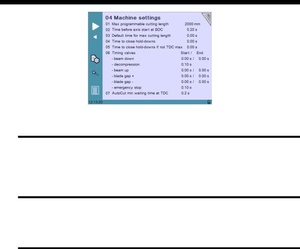
P04 MACHINE SETTINGS
Machine Settings Wizard
When a swing shear machine is used, a Wizard is available by touching the  button. This allows you to measure the default time for the maximum cutting length. See section P04.04 Default Time for Max Cutting Length for more details.
P04.01 Max Programmable Cutting Length
This parameter is only available with swing shear machines. It is the maximum cutting length, depending on the machine dimensions.
P04.02 Time Before Axis Start at BDC
After the beam begins to move up from BDC, this is an extra time that can be set before axes (sheet support and back gauge begin to move. This parameter is only active if P05.01 Axes Start At is set to BDC.
PM_CybTouch6_ Shears_v2.0.doc |
page 16 of 55 |
v2.0 |
Nov.12 |
P04.03 Default Time for Max Cutting Length
This is the default time it takes to cut a piece with the previously set maximum cutting length in P01 Maximum Cutting Length.
This is the value set by default when working in the EasyCut and Program page.
This is also the maximum time the operator can program.
This parameter is only available with swing shear machines.
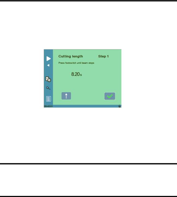
This time can easily be measured using the Wizard:
1. Touch the  button, the below Wizard is displayed:
2.Press the foot pedal to lower the beam, the time it takes for the beam to go from TDC position to BDC is measured (here 8.20 seconds).
3.Touch the  button to exit the Wizard and return to the machine parameters page.
4.The programmed cutting length value is now set.
P04.04 Time to Close Hold-Downs
This parameter determines the time before the output Time hold dn closed (for closing the holdowns) is activated after the beam starts to descend from TDC max.
P04.05 Time to Close Hold-Downs if not TDC max
This parameter determines the time before the output Time hold dn closed (for closing the holdowns) is activated after the beam starts to descend from a point below TDC max, upon pressing foot pedal.
PM_CybTouch6_ Shears_v2.0.doc |
page 17 of 55 |
Loading...