

Page 1

ENGLISH
GB
Use and maintenance manual
General Index
1. FOREWORD 3
1.1 GENERAL 3
1.2 PURPOSE OF THE MANUAL 3
1.3 WHERE AND HOW TO KEEP THE MANUAL 3
1.4 MANUAL UPGRADES 3
1.5 COLLABORATION WITH USERS 4
1.6 MANUFACTURER 4
1.7 MANUFACTURER'S RESPONSIBILITY AND WARRANTY 4
1.7.1 Terms of warranty 4
1.8 TECHNICAL ASSISTANCE SERVICE 5
1.9 COPYRIGHT 5
2. MACHINE DESCRIPTION 6
2.1 PURPOSE 6
2.2 TECHNICAL SPECIFICATIONS 6
2.3 DIMENSIONS AND WEIGHTS 6
3. STARTING 7
4. CONTROL PANEL 10
5 USE OF THE WHEEL BALANCER 11
5.1 PRESETTING OF WHEEL DIMENSIONS 11
5.1.1 Automatic
5.1.2 Modifying set dimensions 12
5.1.2.1 Standard correction method 12
5.1.2.2 Correction method with adhesive weights (ALU) 12
5.1.3 Static & combined modes 12
5.2 MEASUREMENT RESULT 13
5.3 EXACT POSITIONING OF THE ADHESIVE WEIGHT BY MEANS OF THE GAUGE WITH CLIPS 13
5.4 SPLIT FUNCTION (UNBALANCE RESOLUTION) 13
5.5
AUTOMATIC MINIMIZATION OF STATIC UNBALANCE 14
6. SETUP 15
6.1 MENU 15
6.2 UNBALANCE OPTIMISATION 16
6.3 SELF-DIAGNOSTICS 16
6.4 CALIBRATION 16
6.5 AUTOMATIC GAUGES CALIBRATION 17
6.5.1 Rim distance gauge 17
6.5.2 Diameter gauge 17
6.5.3 Width sonar (option) 18
7. DIAGNOSTICS 19
width 11
I 0984_0985 - 10/11 - Rev. B
Page 2

7.1 INCONSISTENT UNBALANCE READINGS 19
7.2 ALARM SIGNAL 19
8. MAINTENANCE 22
8.1 GENERAL 22
8.1.1 Introductory notes 22
8.1.2 Safety rules 22
8.1.3 Replacing fuses 22
8.1.4 Touch panel cleaning 22
9. DISPOSAL 23
9.1 DISPOSING OF THE BALANCER 23
9.2 DISPOSING OF ELECTRONICS COMPONENTS 23
10. SPARE PARTS 23
10.1 IDENTIFICATION AND ORDERING METHOD 23
11. ATTACHED DOCUMENTATION 23
Page 3

Use and maintenance manual Rev. 10-2011
1. Foreword
WARNING
THIS MANUAL IS AN INTEGRAL PART OF THE INSTALLATION
MANUAL WHICH SHOULD BE CONSULTED CONCERNING STARTING
AND USING THE MACHINE SAFELY.
READ CAREFULLY BEFORE CONTINUING.
1.1 GENERAL
The machine has been constructed in conformity with the
current EC Directives and the technical standards implementing the requirements, as stated in the declaration
of conformity issued by the manufacturer and attached
to the manual.
This publication, hereinafter simply referred to as ‘man-
ual’, contains all the information required to safely use
and service the machine referred to in the Declaration of
Conformity.
This appliance, hereinafter is generically referred to as
‘machine’.
The manual addresses operators instructed on the precautions to take in relation to the presence of electric current
and moving devices.
This publication is intended for all ‘users’ who as far as
within their competence need to and/or are obliged to
give instructions to others or operate on the machine
themselves.
These persons can be identified as follows:
- operators directly involved in transporting, storing,
installing, using and servicing the machine from when
it is put on the market until when it is scrapped;
- direct private users.
The original Italian text of this publication constitutes the
only reference to resolve any interpretation controversies
related to the translation into the European Community
languages.
This publication forms an integral part of the machine
and must therefore be kept for future reference until final
dismantling and scrapping of the machine.
ENGLISH
1.2 PURPOSE OF THE MANUAL
This manual, and the installation manual, contains the
instructions required to use the machine safely and carry
out routine maintenance work.
Any calibrations, adjustments and extraordinary maintenance operations are not considered in this document as
they may only be performed by the service engineer who
must work on the machine according to the technical and
rated characteristics for which it was built.
Though it is fundamental to read this manual, it cannot
replace skilled technical staff who must be adequately
trained beforehand.
The foreseen use and configurations of the machine are
the only ones allowed by the manufacturer; do not attempt
to use the machine in a different way.
Any other use or configuration must be agreed in advance
with the manufacturer in writing and in this case an annex
will be attached to this manual.
For use, the user must also comply with the specific
workplace legislation in force in the country where the
machine is installed.
The manual also refers to laws, directives, etc., that the
user must know and consult in order to accomplish the
goals that the manual sets out to achieve.
1.3 WHERE AND HOW TO KEEP THE
MANUAL
This manual (and relative attachments) must be kept in
a safe and dry place and must always be available for
consultation.
Make a copy and keep it in the archive.
When exchanging information with the manufacturer or
the technical assistance staff authorised by the former,
quote the rating plate information and the serial number
of the machine.
This manual must be kept for the entire lifetime of the
machine, and if necessary (e.g.: damage making all or
some of it illegible, etc.) the user must request another
copy exclusively from the manufacturer, quoting the publication code indicated on the cover.
Introduction
1.4 MANUAL UPGRADES
This manual is an integral part of the machine and reflects
the state of the art at the moment it was put on the market.
The publication complies with the directives in force on
that date; the manual cannot be considered inadequate
3
Page 4
Use and maintenance manual Rev. 10-2011
as a result of regulatory updates or modifications to the
machine.
Any manual upgrades that the manufacturer may see fit to
send to users will become an integral part of the manual
ENGLISH
and must be kept together with it.
1.5 COLLABORATION WITH USERS
The manufacturer will be pleased to provide its customers with any further information they may require and will
consider proposals for improving this manual in order to
more fully satisfy the requirements it was written for.
In case of transfer of ownership of the machine,
which must always be accompanied by the use and
maintenance manual, the original user must inform
the manufacturer of the name and address of the
new user in order to allow it to send the new user
any communications and/or updates deemed to be
indispensable.
This publication is the property of the Manufacturer
and may not be fully or partly reproduced without prior
written agreement.
in this manual
- use of the machine by people who have not read and
fully understood the contents of this manual;
- use in breach of specific regulations in force in the
country of installation;
- modifications made to the machine, software and operating logic, unless authorised by the manufacturer
in writing;
- unauthorised repairs;
- exceptional events.
Transfer of the machine to a third party must also include
this manual; failure to include the manual automatically
invalidates all the rights of the purchaser, including the
terms of warranty, where applicable.
If the machine is transferred to a third party in a country with
a different language from the one written in this manual,
the original user shall provide a faithful translation of this
manual in the language of country in which the machine
will operate.
1.7.1 Terms of warranty
The Manufacturer guarantees the machines it manufacturers against all manufacturing or assembly faults for 12
(twelve) months from the date of collection or delivery.
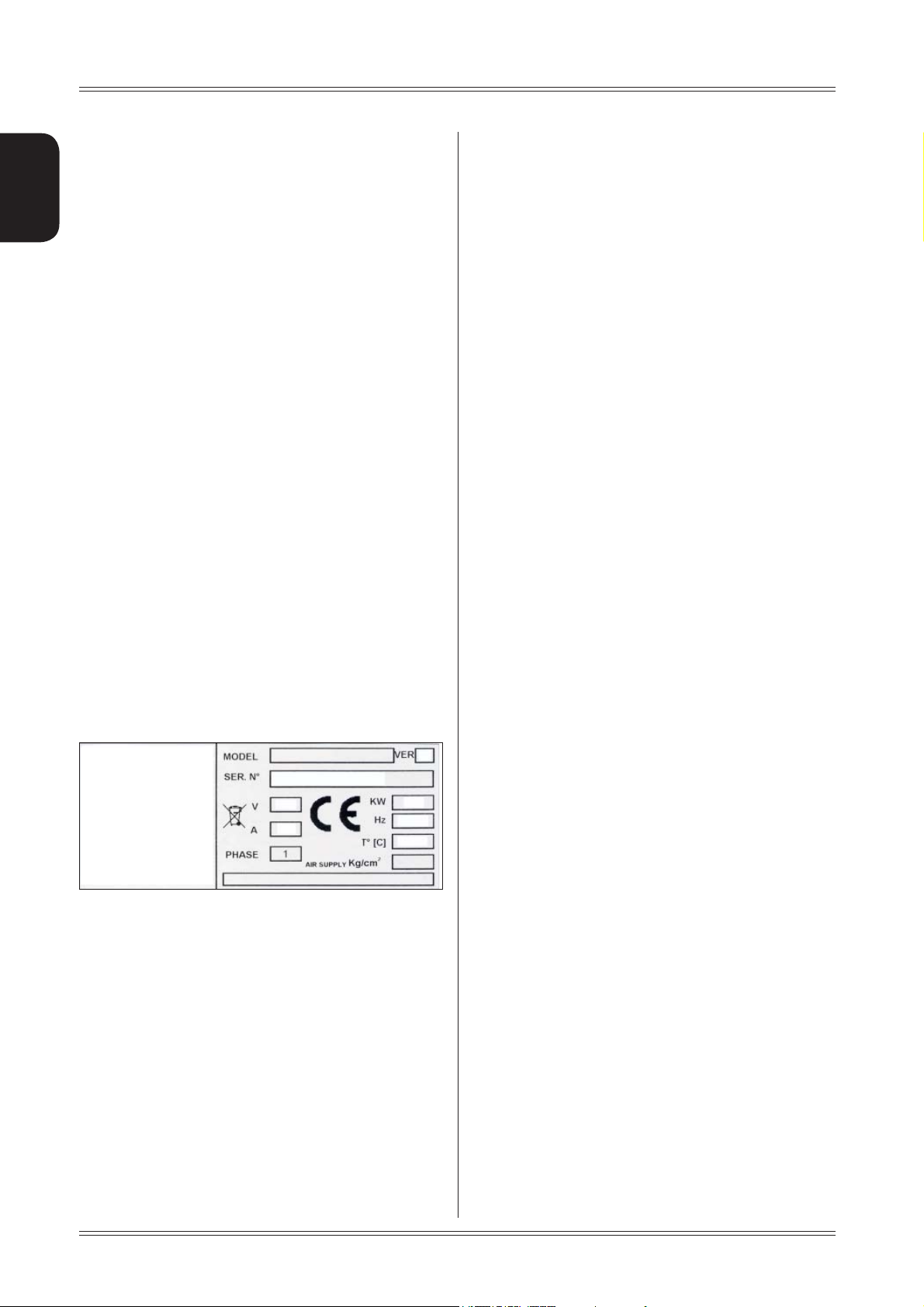
1.6 MANUFACTURER
The machine identification data is indicated on the plate
mounted on the machine.
The plate below is shown for the sake of example.
1.7 MANUFACTURER'S RESPONSIBILITY
AND WARRANTY
In order to make use of the manufacturer's warranty, the
user must scrupulously observe the precautions contained
in the manual, in particular he must:
- never exceed the limits of use of the machine;
- always constantly and carefully clean and service the
machine;
- have the machine used by people of proven capacity
and attitude, adequately trained for the purpose.
The manufacturer declines all direct and indirect liability
caused by:
- use of the machine in a different way from that indicated
The Manufacturer undertakes to replace or repair any part
which it deems to be faulty free of charge at its factory,
carriage paid.
If a Manufacturer's repairman (or a person authorised by
the same) is required to work at the user's facilities, the
relative travel expenses and board and lodging shall be
charged to the user.
The free supply of parts under warranty is always subject
to the faulty part being inspected by the manufacturer (or
a person authorised by the same).
The warranty is not extended following repairs or other
work done to the machine.
The warranty does not cover damage to the machine
deriving from:
- transport;
- neglect;
- improper use and/or use not in compliance with the
instructions in the operating manual
- incorrect electrical connections.
The warranty is invalidated in case of:
- repairs made by people who were not authorised by
the manufacturer;
- modifications that were not authorised by the manufacturer;
- use of parts and/or equipment that were not supplied
or approved by the manufacturer;
- removal or alteration of the machine identification
plate.
4
Introduction
Page 5

Use and maintenance manual Rev. 10-2011
1.8 TECHNICAL ASSISTANCE SERVICE
For any technical service operation, contact the manufacturer
directly or an authorised dealer always quoting the model,
the version and the serial number of the machine.
1.9 COPYRIGHT
The information contained in this manual may not be
disclosed to third parties. Partial or total duplication, unless authorised by the Manufacturer in writing, through
photocopying, duplication or other systems, including
electronic acquisition, is breach of copyright and can lead
to prosecution.
ENGLISH
Introduction
5
Page 6
2. Machine description
ENGLISH
Use and maintenance manual Rev. 10-2011
2.1 PURPOSE
The ER80/ER80 SE is used to balance the wheels of cars,
vans, 4-WD, motorcycles and scooters. The wheels must
weigh less than 75 kg. It can be operated in the temperature range of 0° to + 45°C.
The machine can operate only on fl
To lift the machine, lever only on the base where the 3
support points are located. never, under any circustance,
apply force to other points such as the spindle, head, or
accessory shelf. It functions properly without having to
fasten it to the floor with wheels weighing up to 35 kg; for
heavier wheels, fasten it at the points indicated. Do not
mount anything other than motorbike, car or truck tyres
on the wheel balancer.
Thanks to the new and exclusive VDD (Virtual Direct Drive)
system, reliable unbalance measurements can be made
in a short time, almost half the time of the cycle used with
respect to other balancers in this range.
1
at non resilient fl oor.
2
4
3
The main features include:
machine settings menu. ▪
touch panel ▪
adhesive weight positioning laser ▪
rim interior light ▪
wheel locking ▪
automatic width ▪
static programme, ▪ ALUS; SPLIT; Unbalance optimiza-
tion; indication of exact correction weight position; Self
diagnostics; Calibration.
automatic minimisation of static unbalance ▪
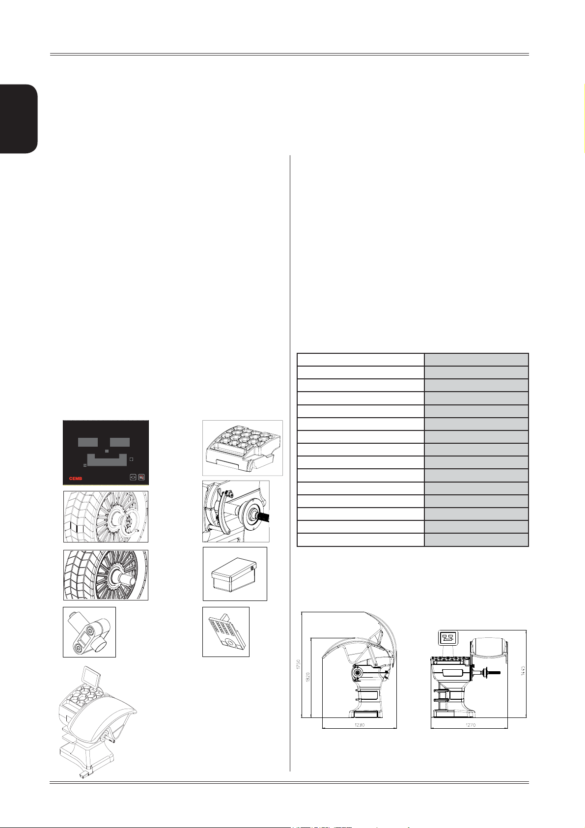
2.2 TECHNICAL SPECIFICATIONS
The following data refers to the balancer in its standard
configuration.
Single-phase power supply 115 / 230 V 50/60 Hz
Protection class IP 54
Max.power consumption 0,15 Kw
Balancing speed 100 min
Cycle time for wheel 4.7 sec. (5 3/4”x14”) 15 Kg.
Measurement uncertainty 0,5 g
Average noise < 70 dB (A)
Rim width setting range 1.5” ÷ 20” or 40 ÷ 510 mm
Diameter setting range 10” ÷ 30” or 265 ÷ 765 mm
Min/max. compressed air pressure 8 ÷ 10 kg/cm
Maximum wheel weight < 75 Kg.
Machine weight 120 Kg.
-1
2
approx. 0.8 to 1 Mpa;
approx. 8 to 10 bar;
approx. 115 to 145 psi.
5
6
2.3 DIMENSIONS
7
Machine description
6
8
TOUCH CONTROL PANEL1.
WEIGHT-TOOL HOLDER2.
LOCK NUT3.
AUTOMATIC GAUGE4.
COLLAR (VERS. SE)5.
BP PEDAL6.
WHEEL POSITIONING LASER7.
WHEEL INTERIOR LED LIGHT8.
Page 7

Use and maintenance manual Rev. 10-2011
3. Starting
ENGLISH
7. Position the wheel on the terminal with the inner part
facing the balancer;
BEFORE SWITCHING ON THE MACHINE, MAKE SURE THAT ALL THE
WARNING
CONNECTIONS DESCRIBED IN THE INSTALLATION CHAPTER
HAVE BEEN MADE CORRECTLY.
THE FOLLOWING OPERATIONS INVOLVE A POTENTIAL RISK FOR
THE OPERATOR, GIVEN THE PRESENCE OF VOLTAGE ON THE
EQUIPMENT. THE PERSONAL PROTECTIVE EQUIPMENT DESCRIBED
IN THE INSTALLATION MANUAL MUST BE WORN AND WORK
MUST BE DONE WITH DUE CARE AND ATTENTION.
OPERATIONS MAY ONLY BE PERFORMED BY A
SPECIALISED TECHNICIAN.
Before powering the machine, carry out the following
checks:
1. check that the balancing machine touches the floor
at the three support points;
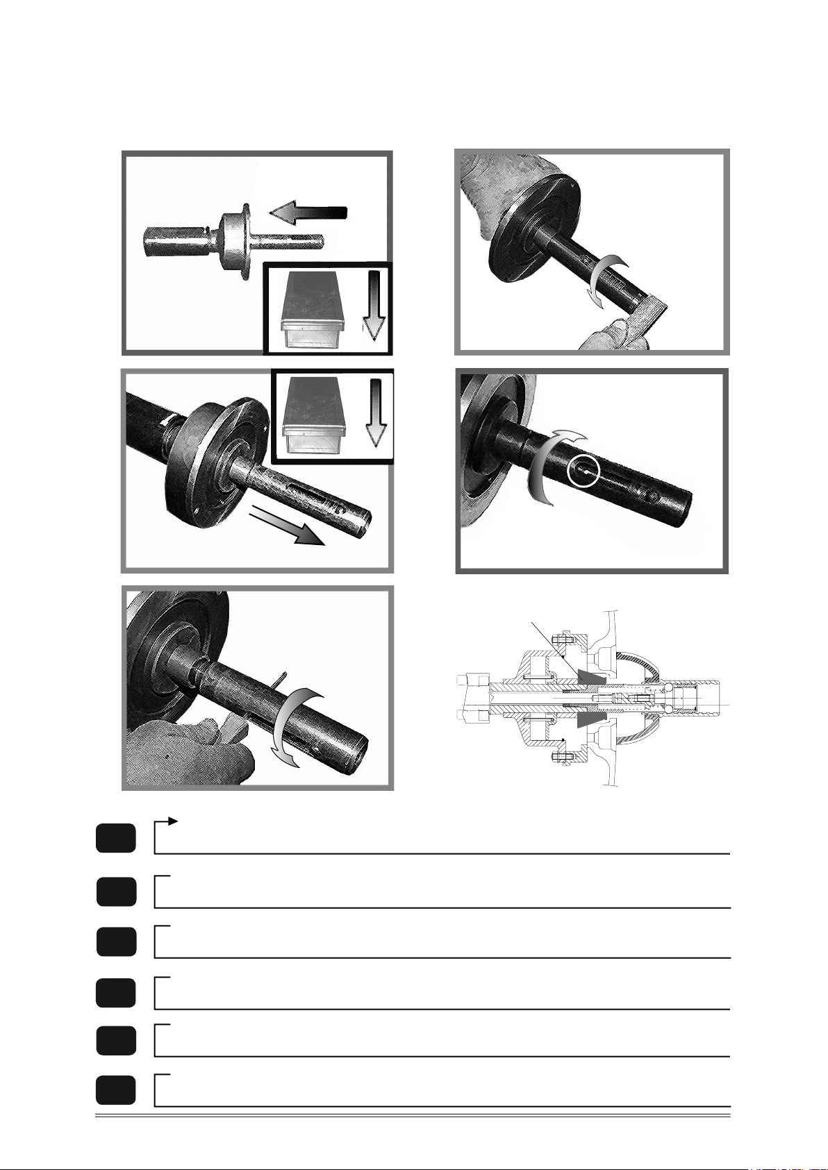
8. Firmly attach the wheel to the balancer shaft using
the lock nut. In the pneumatic version, use the spe
cific collar provided. For operation of the spindle
with pneumatic locking (constant thrust air spring)
connect the wheel balancer to the compressed air
mains. The connection fitting is located at the back
of the machine. At least 8 Kg/cm
2
(~ 0.8 MPa; ~
8 BAR; ~ 115 PSI) pressure is needed for correct
operation of the release device.
9. In the pneumatic version, the pedal allows faste
ning/releasing the wheel on the adapter using the
collar. Press downwards to enable/disable the lock.
2. make sure that all the parts of the balancer are cor
rectly connected and fixed;
3. make sure that the parameters (voltage and frequency)
of the mains power supply are compatible with those
indicated on the rating plate of the balancer;
4. make sure the power cable is correctly connected;
5. make sure the machine shaft and flange hole are
clean.
CAUTION
ANY TRACES OF DIRT MAY AFFECT BALANCING ACCURACY.
6. to turn on the wheel balancer press the switch on
the rear of the machine without touching the ma chine head
10. At this point, you can read the tyre measurements
and perform balancing.
11. Lower the splash guard, when fitted, and press the
START button to perform the spin.
12. The wheel is automatically locked when reaching
the correct angular position for weight application
on the inside and outside, turning it slowly by hand.
To unlock the wheel, turn it hard to move it from the
correct correction position. If the unbalance is within
tolerance, the wheel is locked automatically.
WARNING
IT IS PROHIBITED TO TOUCH ANY PART OF THE MACHINE
DURING THE BALANCING CYCLE.
Starting
7
Page 8

SE2-MOUNTING
A
C
B
D
E
G
F
SE2 MOUNTING
Page 9
360°
Cone
Quando possibile, centrare le ruote con cono dall'interno (vedi disegno).
Evitare di usare il manicotto RL con cerchi di ferro.
Whenever possible, centre the wheels with the cone from the inside (see the drawing
).
Avoid using the RL sleeve with metal rims.
Lorsque c’est possible, centrer les roues avec le cône de l’intérieur (voir dessin).
Eviter d’utiliser le manchon RL avec les jantes en fer.
Wenn möglich, die Räder mit Konus von Innen heraus zentrieren (siehe Zeichnung).
Bei Eisenfelgen die Verwendung der Muffe RL vermeiden.
Siempre que sea posible, centrar las ruedas con cono desde dentro (véase dibujo).
Evitar usar el manguito RL con llantas de hierro.
Quando possível, centre as rodas com cone pelo lado de dentro (ver
� gura).
Evite utilizar a luva RL com jantes de ferro.
SE2-DISMOUNTING
A
B
C
D
E
IT
GB
FR
DE
ES
PT
SE2 DISMOUNTING
Page 10

4. Control panel
ENGLISH
Use and maintenance manual Rev. 10-2011
12
3
7
1-2 Digital readouts, AMOUNT OF UNBALANCE, inside/outside
Buttons to read unbalance below threshold
3-4 Digital readouts, POSITION OF UNBALANCE, inside/outside
5
6
7 Position repeater push button
8 Push button, SPLIT (unbalance spread)
9 Dot matrix function display
Push button, FUNCTIONS MENU
Wheel locking push button
RED
GREEN
YELLOW
9
4
8
6
5
10
THE FUNCTION BUTTONS ARE SELECTED BY PRESSING ON THE TOUCH PANEL.
CAUTION
PRESS THE BUTTONS WITH YOUR FINGERS. NEVER USE THE COUNTERWEIGHT GRIPPERS OR OTHER POINTED OBJECTS!
WHEN THE BEEP SIGNAL IS ENABLED PRESSING OF ANY PUSH BUTTON IS ACCOMPANIED BY A “BEEP”.
Control panel
Page 11

Use and maintenance manual Rev. 10-2011
5 Use of the wheel balancer
5.1 PRESETTING OF WHEEL DIMENSIONS
The balancing data is set by means of an “intelligent” automatic gauge; confi rmation of the measurement and the
position appear on the display. The round part of the gauge
must rest on the rim where the weight will be positioned.
b) adhesive weights: make two successive measurements
on two correction planes inside the rim.
The balancing machine automatically interprets that the
correction will be made with adhesive weights and the
following appears:
ENGLISH
a
b
While the gauge is moving the following appears:
when the measurement has been stored:
For a different combination of the type or position of the
weights on the rim, press the matrix at points near the
rim symbol.
5.1.1 Automatic width
At the end of the automatic measurement of the distance
and diameter the following appears:
For large wheels (e.g. off-road vehicles, light trucks or wheels
protruding far out from the rim) press the
switch from:
button to
a) standard weights: when only one measurement is
made, the machine interprets the presence of a rim with
clip-on weight correction
Use of the wheel balancer
N.T. = NORMAL TYRE
L.T. = LIGHT TRUCK
Close the guard to perform an unbalance measurement
spin.
11
Page 12

Use and maintenance manual Rev. 10-2011
.
5.1.2 Modifying set dimensions
If the wheel dimensions have been entered incorrectly,
the parameters can be modified without repeating the
balancing spin:
ENGLISH
Press the button
to the next dimension. Press the button
time to interrupt dimension setting and return to the main
screen.
to confirm the setting and go
at any
5.1.3 Static & combined modes
To change the application position of the correction weights,
press on the display near the rim section (central part of
the display):
1
23
Press near the red/orange LEDs 1-2-3-4-5.
Light alloy rim balancing with adhesive weight on the
outside (inside the rim) and adhesive or clip-on weight
on the inside:
5
4
6
5.1.2.1 Standard correction method
Set the value of the dimensions in sequence:
b=width
d=diameter
a=distance
using the buttons
Press the button
the next dimension.
Press the button
setting and return to the main screen.
/
to confirm the setting and go to
at any time to interrupt dimension
.
5.1.2.2 Correction method with adhesive
weights (ALU)
Set the value of the dimensions in sequence:
aI=inside weight distance
aE=outside weight distance
dI=inside weight distance
dE=outside weight distance
using the buttons
/
.
STATIC (press twice near the LED 3 ):
Iron rim combined balancing:
To return to the main screen, press the button
perform a spin, close the guard.
. To
12
Use of the wheel balancer
Page 13

Use and maintenance manual Rev. 10-2011
5.2 MEASUREMENT RESULT
After performing a balancing spin, the unbalance values
are shown on the displays 1-2. The symbol shown on the
LED displays 3-4 and highlighted in the figure indicates the
correct angular position of the wheel in order to apply the
counterweights (12 o’clock) (for clip-on weights 6 o’clock
with laser indication for adhesive weights).
If the wheel clamp option is enabled (see
wheel is automatically clamped in the correction position.
Pressing
the chuck can be locked/released in any
MENU), the
a beep.
If gauge locking is enabled (see MENU), the gauge
is automatically locked in position to prevent weight
application problems. To release the gauge, lower it
towards the spindle, or if this is not possible, move the
wheel.
Rotate the gauge until the correction weight adheres ▪
to the rim
the fact that the weight application position is no longer ▪
vertical is automatically compensated.
- INSIDE CORRECTION POSITION
- OUTSIDE CORRECTION POSITION
ENGLISH
position to facilitate mounting the wheel (see
If the unbalance is within tolerance, 0 (zero) is displayed;
touching the display near any of the unbalance values,
you can read the values below the required tolerance
threshold.
MENU).
5.3 EXACT POSITIONING OF THE ADHESIVE
WEIGHT BY MEANS OF THE GAUGE WITH
CLIPS
P ▪ ress if using the correction method with adhe-
sive weights on the inside of the rim
FI
Fit the correction weight in the specific gauge seat with ▪
the adhesive part facing upwards
Bring the wheel into correct angular position for the ▪
plane to be corrected
If the wheel clamp option is enabled (see ▪
is automatically clamped in the correction position.
withdraw the gauge until the correction plane indication ▪
arrows turn green
If the buzzer is enabled (see ▪
of the weight application distance is accompanied by
FE
MENU),the wheel
MENU), the attainment
To cancel the function, press the
button again.
5.4 SPLIT FUNCTION
(unbalance resolution)
The SPLIT function is used to position the adhesive weights
behind the wheel spokes (angle > 18°) so that they are no
longer visible (for alloy rims). Use this function in the ALU
or STATIC mode where the adhesive weight is applied to
the outer side of the rim.
Close the guard to perform an unbalance measurement
spin.
position the unbalance to be split in the correction ▪
position in order to turn on the laser.
press and hold the button ▪
to the spoke you wish to correct.
release the button ▪
Turn th ▪ e wheel in the direction of rotation of the unba-
lance indicated on the display until the second spoke
is in the position indicated by the laser and press
position t ▪ he wheel as indicated by the LEDs. The un-
balance is indicated on the display
To return to the normal unbalance indication press
.
until the laser points
Use of the wheel balancer
13
Page 14

x
g
g
x
°
x
g
g
x
g
g
g
g
x
g
g
x
x
g
g
x
x
g
g
x
Use and maintenance manual Rev. 10-2011
The spoke-to-spoke distance must be a minimum of
18° and a maximum of 120° (if not, errors 24,25,26 appear). Spokes with irregular or inconstant angles can be
ENGLISH
compensated.
If the laser option is disabled (MENU), operate as fol-
lows:
turn the wheel to the correction position of the unba- ▪
lance to be split.
move one of the spokes where you want to split the ▪
unbalance to 12 o’clock (e.g. 1) and press
Following ▪ the direction of rotation indicated by the
position LED’s, move spoke 2 to12 o’clock and press
. The value to use for correction in position 2 is
displayed
position the wheel on spoke 1 following the LED indi- ▪
cator and correct the unbalance as indicated on the
displays.
To return to the normal unbalance indication press
INFORMATION
.
5.5 AUTOMATIC MINIMIZATION OF STATIC
UNBALANCE
Initial unbalance
ssx
ddx
g
g
static residue
g
5500°
ssx
g
unbalance
ddx
11 g
g
ssx
g
static residue
ddx
g
66 g
Phase shift
Possible approximations
ssx
ddx
g
static residue
With traditional wheel
44 g
balancer
g
ssx
g
static residue
ddx
33 g
Choice with minimum static
This program is designed to improve the quality of balancing
without any mental effort or loss of time by the operator. In
fact by using the normal commercially available weights, with
pitch of 5 in every 5 g, and by applying the two counterweights
which a conventional wheel balancer rounds to the nearest
value, there could be a residual static unbalance of up to 4
g. The damage of such approximation is emphasized by the
fact that static unbalance is cause of most of disturbances
on the vehicle. This new function, resident in the machine,
automatically indicates the optimum entity of the weights
to be applied by approximating them in an “intelligent” way
according to their position in order to minimize residual static
unbalance.
14
Use of the wheel balancer
Page 15

Use and maintenance manual Rev. 10-2011
ENGLISH
6. Setup
6.1 MENU
This is used to personalise some balancer functions and to perform calibrations.
To access this section, press the
button.
See chapter on unbalance optimisation
See MANUAL DIMENSION PRESETTING
diameter mm/inch
width mm/inch
approximates
1-5g 0.1-0.25oz
on/off beep signal
See AUTO-DIAGNOSTICS
See CALIBRATION
unbalance unit of measure
g/.oz
screen saver operating
time in minutes
on/off wheel locking
on/off gauge locking
Rim interior light on/off
laser unbalance
position on/off
Calibration of automatic RIM DISTANCE gauge
Calibration of automatic DIAMETER gauge
WIDTH calibration
RETURN TO MEASUREMENT SCREEN
Setup
15
Page 16
Use and maintenance manual Rev. 10-2011
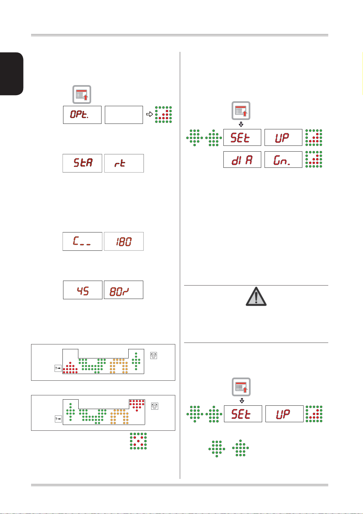
6.2 UNBALANCE OPTIMISATION
This operation is performed to reduce the static unbalance of the wheel.
It is suitable for static unbalance values in excess of 30
ENGLISH
grams.
Ia. f no unbalance was measured before, START appears
on the display. Press this button to proceed. Close the
guard to perform a spin.
Makb. e a reference mark on the flange and the rim (using
a piece of chalk, for example).
With the aid of a tyre remover, turn the tyre on the rim
by 180°.
Refi t the wheel in such a way that the reference marks
on the rim and the fl ange coincide.
Close the guard to perform a spin.
6.3 SELF-DIAGNOSTICS
The machine can perform self-diagnostics to check the
LED’s on the control panel and make sure the encoder
reads correctly.
To perform this operation, view the SETUP menu.
In the self-diagnostics sequence, all the LED’s on the panel light up for a few seconds in order to check operation.
When the LED’s go out, the machine automatically moves
on to the encoder reading phase. When the wheel is turned
manually (forwards and backwards), the display shows its
exact position. The value lies between 0 (zero) and 255.
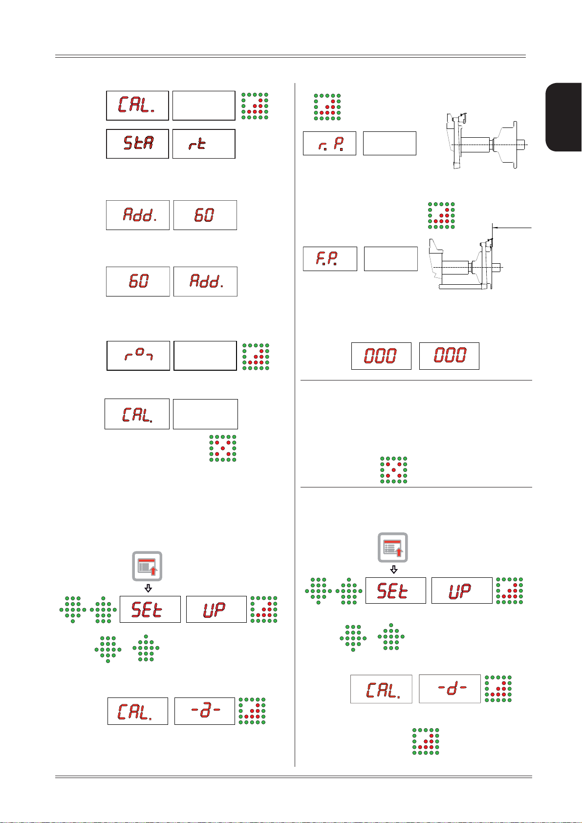
6.4 CALIBRATION
RH displc. ay: percentage reduction value
LH display: actual static unbalance value which can be
reduced by rotation
Mad. rk the two positions of the rim and tyre, and turn the
tyre on the rim until the positions coincide to achieve
the optimisation shown on the display
TYRE POSITION
RIM POSITION
To calibrate the machine, proceed as follows:
Fit an average size wheel with a metal rim on the shaft. ▪
Example: 6” x 15” (± 1”).
Set the wheel measurements as described in paragraph ▪
USE OF THE WHEEL BALANCER.
CAUTION
SETTING INCORRECT DIMENSIONS WOULD MEAN THAT THE MACHINE
IS NOT CORRECTLY CALIBRATED, THEREFORE, ALL SUBSEQUENT
MEASUREMENTS WILL BE INCORRECT UNTIL CALIBRATION IS PER-
FORMED ONCE AGAIN WITH THE CORRECT DIMENSIONS.
Display the SETUP menu:
To finish optimisation, press the button
cated on the displays. When optimisation is complete, close
the guard to perform a new spin or press anywhere on the
touch panel to return to the measurement screen.
16
when indi-
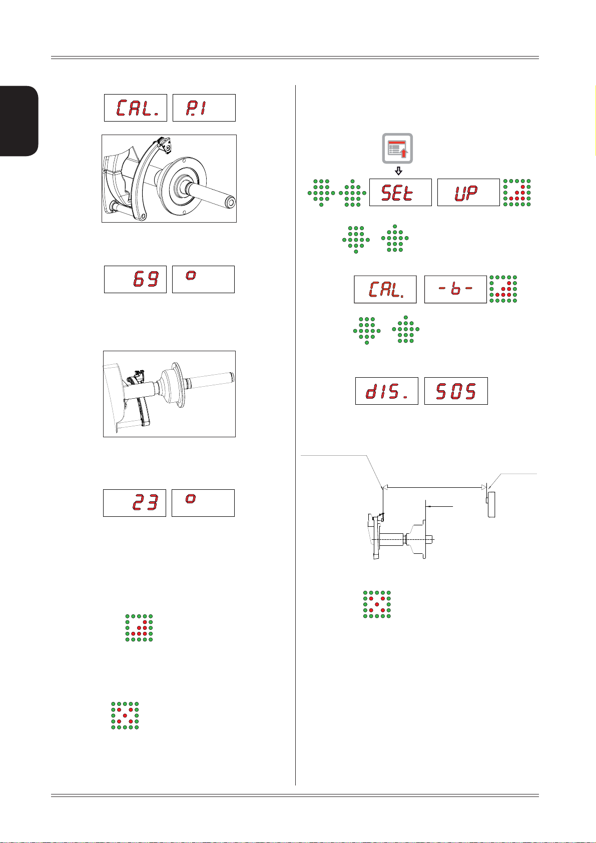
P1. ress
function.
/
to view the CALIBRATION
Setup
Page 17
Use and maintenance manual Rev. 10-2011
Close the guard to perform a spin.
A2. dd a standard weight of 60 g (2.00 oz) to the outer
side, in any position.
.
Close the guard to perform a spin.
Sh3. ift the standard weight from the outside to the
inside keeping the same position.
Leave the distance gauge in rest position and press 2.
ENGLISH
4. Move the distance gauge pusher in line with the
adapter surface and press
Flange plane
Close the guard to perform a spin.
Tu4. rn the wheel until the standard weight is at the top
(12 o’clock).
End of calibration.5.
To cancel calibration at any time, press
.
6.5 AUTOMATIC GAUGES CALIBRATION
6.5.1 Rim distance gauge
Display the SETUP menu
CORRECT CALIBRATION
Return the gauge to rest position.
The wheel balancer is ready for operation.
INDICATION
In the event of errors or faulty operation, the writing
“r.P.”: appears on the display : shift the gauge to the
rest position and repeat the calibration operation exactly
as described above. If the error persists, contact the
Technical Service Department. In the event of incorrect
input in the rim distance gauge calibration function, press
to cancel it.
6.5.2 Diameter gaugeE
Display the SETUP menu
P1. ress
gauge CALIBRATION function.
Setup
/
to view the rim distance
P1. ress
CALIBRATION function.
/
m
Place the gauge rod on the spindle shell as shown 2.
in the figure and press
to view the diameter gauge
17
Page 18
ENGLISH
Use and maintenance manual Rev. 10-2011
6.5.3 Width sonar (option)
Display the SETUP menu
Th3. e number 69 ± 3° appears on the left display .
Turn the gauge downward positioning the gauge rod 4.
in contact with the spindle shell as shown in the
images.
P1. ress
CALIBRATION function.
Set with 2.
en the Sonar sensor (0 sonar) and the end of the
distance gauge (at rest).
A = Distance: Gauge at rest to
Calibro a riposo
/
/
to view the width sonar
the distance in mm betwe
0 sonar
0 Sonar
A
Piano flangia
mber 23 ± 3° should appear on the left
The nu5.
display. The calibration is already correct.
If not, press the
number 23 appears on the left display.
Return the gauge to rest position.
In the event of incorrect input in the diameter gauge calibration
function, press
18
button holding the gauge: the
to cancel it.
In the event of incorrect input in the width gauge calibration
function, press
to cancel it.
Setup
Page 19

Use and maintenance manual Rev. 10-2011
7. Diagnostics
ENGLISH
7.1 INCONSISTENT UNBALANCE
READINGS
In some cases, when a wheel that has just been balanced
is repositioned on the balancer, the machine can detect
an unbalance.
This is not a machine problem but is due to faulty mounting
of the wheel on the flange. In other words, when mounting the wheel after initial balancing, it has taken another
position with respect to the balancer shaft axis.
If the wheel has been mounted on the flange with screws,
the screws may not have been tightened correctly (crisscross sequence) or the tolerances of the holes drilled in
the wheel may be too large. Small errors, up to 10 grams
(0.4 oz), are to be considered normal in wheels locked
with the relative cone: The error is normally greater for
wheels locked with screws or studs.
If, after balancing, the wheel is still unbalanced when refitted on the vehicle, this could be due to an unbalanced
brake drum or, very often, the tolerances of the holes
drilled in the rim and drum are too large. In this case,
balancing should be performed using a balancer with the
wheel mounted on the vehicle.
7.2 ALARM SIGNAL
The machine has a self-diagnostics cycle which identifies the most frequent malfunctions during the normal
work cycle.
These malfunctions are processed by the system and
shown on the display.
Diagnostics
19
Page 20

Use and maintenance manual Rev. 10-2011
ENGLISH
THE INFORMATION IN THE POSSIBLE REMEDY COLUMN REQUIRES WORK TO BE PERFORMED BY SPECIALIST TECHNICIANS OR OTHER AUTHOR-
ISED PEOPLE WHO MUST ALWAYS WORK USING THE PERSONAL PROTECTIVE EQUIPMENT INDICATED IN THE INSTALLATION MANUAL. IN SOME
CASES, THIS WORK CAN BE PERFORMED BY A NORMAL OPERATOR.
WARNING
ERROR CAUSE POSSIBLE REMEDY
Black The wheel balancer does not
switch on.
Check the machine is properly connected to the mains power 1.
supply.
Check the fuses on the power board and replace if necessary.2.
Replace the CPU board.3.
Err. 1 No rotation signal. Use the self-diagnostics function to check the encoder.1.
Replace the encoder.2.
Replace the CPU board.3.
Err. 2 Speed too low during detection.
During the unbalance measurement revolutions, the wheel speed
has fallen to below 42 rpm.
Make sure that a vehicle wheel is mounted on the wheel balancer.1.
Use the self-diagnostics function to check the encoder.2.
Disconnect the piezo connectors from the board and do a spin 3.
(if no error is detected, replace the piezo sensors).
Replace the CPU board.4.
Err. 3 Unbalance too high. Check the wheel dimensions setting.1.
Check the detection unit connections.2.
Run the machine calibration function.3.
Mount a wheel with more or less know4. n unbalance (less than
100 grams) and check the response of the machine.
Replace the CPU board.5.
Err. 4 Rotation in opposite direction. Use the self-diagnostics function to check the encoder.1.
Check the encoder bearing/spring.2.
Err. 5 Guard open
The [START] pushbutton was
pressed without fi rst closing the
guard.
Err. 6 Spindle open (SE version)
The guard has been closed
without fi rst closing the spindle
Err. 7
NOVRAM parameter read error Switch off the machine and wait for at least ~ 1 min;1.
Err. 8
Err. 9
Err. 11 Too high speed error.
The average spinning speed is
more than
240 rpm.
Err.14
Unbalance measurement error. Use the self-diagnostics function to check the encoder.1.
Err.15
Err.16
Err.17
Err.18
Err. 19
Err. 20 Wheel still. The wheel must
remain still for more than one
second after START.
Err
. 21 Motor on for more than 15
seconds.
1. Reset the error.
2. Close the guard.
3. Verify the function of the protection switch.
4. Press the [START] button.
1.
Reset the error
2. Close the spindle
3. Close the guard.
re-start the machine and check it works properly.
Repeat machine calibration.2.
Replace the CPU board.3.
1. Check functioning of the phase encoder and, in particular, the
reset signal.
2. Replace the computer board.
Check the detection unit connections.2.
Check the machine earthing connection.3.
Mount a wheel with more or less known unbalance (less than 4.
100 grams) and check the response of the machine.
Replace the CPU board.5.
Use the self-diagnostics function to check the encoder.1.
Check the connections on the power board.2.
Replace the CPU board.3.
1. Use the self-diagnostics function to check the encoder.
2. Check the connections on the power board.
3. Replace the CPU board.
20
Diagnostics
Page 21

Use and maintenance manual Rev. 10-2011
Err. 22 Maximum number of spins
Err.24 Distance between the spokes
Err.25 Distance between the spokes
Err.26 First spoke too far from the
Unbalance
incorrect
with back
centring
cones
possible for the unbalance
measurement has been exceeded.
less than 18 degrees.
greater than 120 degrees.
unbalance
Wheel slipping on the adapter
because the BP
the end of travel or because of
incorrect fi tting of the tyre tie-rod
system is at
1. Check that a vehicle wheel has been mounted on the wheel
balancer.
2. Check functioning of the phase encoder and, in particular, the
reset signal.
3. Replace the computer board.
The minimum distance between the spokes where the 1.
unbalance is to be split must be greater than 18 degrees.
Repeat the SPLIT function increasing the distance between 2.
the spokes.
The maximum distance between the spokes where the 1.
unbalance is to be split must be less than 120 degrees.
2. Repeat the split function increasing the distance between the
spokes.
The maximum 1. distance between the unbalance position and
the spoke must be less than 120 degrees.
Repeat the split function increasing the distance between the2.
spokes and the unbalance.
Mount the wheel in vertical position and push the sleeve up
against the wheel. If necessary, repeat locking/unlocking/locking
and perform the procedure again.
ENGLISH
Diagnostics
21
Page 22
8. Maintenance
ENGLISH
Use and maintenance manual Rev. 10-2011
8.1 GENERAL
CAUTION
BEFORE PERFORMING ANY MAINTENANCE OPERATIONS, MAKE SURE
THE MACHINE HAS BEEN DISCONNECTED FROM THE MAINS POWER
SUPPLY. ALWA YS USE THE PERSONAL PROTECTIVE EQUIPMENT
INDICATED IN THE INSTALLATION MANUAL.
8.1.1 Introductory notes
This machine has been designed so as not to require routine maintenance, apart from accurate periodic cleaning.
It is important to keep the machine perfectly clean in order to prevent dust or impurities from compromising the
operation of the balancer.
WARNING
THE PEOPLE RESPONSIBLE FOR CLEANING THE AREA WHERE THE
MACHINE IS INSTALLED MUST WEAR PERSONAL PROTECTIVE EQUIPMENT
IN ORDER TO WORK IN SAFETY AND ACCORDING TO THE CURRENT
OCCUPATIONAL HEATH AND SAFETY REGULATIONS.
Specialist staff must be authorised and especially trained
concerning the dangers that may arise during operation
and the correct methods for avoiding them.
They must always work with great care and pay full attention.
If, exceptionally, the staff removes the guards to carry out
a particular specialist technical maintenance, inspection
or repair job, they are required to put them back after
work.
After work, staff must make sure that foreign objects, in
particular mechanical pieces, tools or devices used during the operative procedure that could cause damage or
malfunctions are not left inside the balancer.
For safety, before starting work, maintenance, inspection
and repair staff must disconnect all power sources and
take all the necessary preventive safety measures.
As well as operating frequencies, the operations described
below indicate the qualifications that staff must possess
in order to perform the operation.
8.1.3 Replacing fuses
Some protection fuses are located on the power board
(see wiring diagrams) accessible by dismantling the weight
shelf). If fuses require replacement, use ones with an
identical current intensity.
As extraordinary maintenance must be performed by service
staff or, in any case, by specifically authorised and trained
people, is not dealt with in this manual.
8.1.2 Safety rules
Performing specialist activities on the equipment, particularly if the guards need to be dismounted, exposes people
to serious danger due to the presence of potentially live
parts.
The rules shown below must be scrupulously followed.
People must always use the Personal Protective Equipment indicated in the Installation Manual. During activities, unauthorised people may not access the equipment
and WORK IN PROGRESS signs will be erected in the
department in such a way that they are visible from every
place of access.
8.1.4 Touch panel cleaning
Use a soft cloth and NON-ABRASIVE commercial glass/plastic
cleaning spray or ethanol or natural detergents.
DO NOT USE:
Organic solvents type nitro thinner ▪
T
urpentine ▪
Petrol ▪
Trichloroethylene ▪
Acetone ▪
22
Maintenance
Page 23

Use and maintenance manual Rev. 10-2011
9. Disposal
CAUTION
THE INSTRUCTIONS IN THIS CHAPTER ARE INDICATIVE. REFER TO
THE REGULATIONS IN FORCE IN THE COUNTRY WHERE THE EQUIP-
MENT IS USED.
9.1 DISPOSING OF THE BALANCER
The balancer must be disposed of after dismounting the
various parts.
For disposal operations, as well as wearing the Personal
Protective Equipment indicated in the INSTALLATION
MANUAL, refer to the instructions and diagrams in this
manual. If necessary, request specific information from
the manufacturer.
Once you have removed the various parts and components,
separate them into the different types of materials according
to the differentiated waste disposal regulations in force in
the country where the machine is dismantled.
If the various components must be stored before being
taken to the dump, make sure to keep them in a safe place
protected from atmospheric agents in order to prevent them
from contaminating the ground and the water table.
10.
Spare parts
10.1 IDENTIFICATION AND ORDERING
METHOD
The various parts can be identified using the explodeddrawings, the electrical drawings and diagrams in the machine
technical file which is archived by the Manufacturer to
which a request can be made.
For off-the-shelf parts, the technical manuals or the supplier's
original documents can be provided if the Manufacturer
deems this to be useful.
If not supplied, this documentation is also included in the
machine Technical File, archived by the Manufacturer, as
regards by Ministerial Decree 98/37/EC.
In this case, contact the Technical Service to identify the
required piece.
If the required pieces are not in any position or they can-
not be identified, contact the Technical Service, specifying the type of machine, its serial number and year of
construction.
This information is indicated on the machine identification plate.
ENGLISH
9.2 DISPOSING OF ELECTRONICS
COMPONENTS
Community directive 2002/96/EC, assimilated in Italy with legislative decree n° 151
of 25th July 2005, requires electrical and
electronic equipment manufacturers and
users to comply with a number of obligations concerning the collection, treatment,
recovery and disposal of this waste.
Please scrupulously comply with these waste
disposal regulations.
Remember that abusive dumping of this waste leads to
the application of the administrative penalties established
by current law.
Disposal – Spare parts – Attached documents
11. Attached
documentation
If not supplied, this documentation is included in the Technical File of the machine, archived by the Manufacturer.
In this case, contact the Technical Service for detailed
information concerning the machine.
23
Page 24

 Loading...