

Page 1

Operating instructions
Contents page
1- GENERAL ................................................................................................................................................................................. 3
1.1 - GENERAL SAFETY RECOMMENDATIONS ............................................................................................................ 3
1.1.1 - STANDARD SAFETY DEVICES ................................................................................................................ 3
1.2 - FIELD OF APPLICATION ......................................................................................................................................... 3
1.3 - OVERALL DIMENSIONS ......................................................................................................................................... 3
1.4 - SPECIFICATION ...................................................................................................................................................... 4
2 - HANDLING AND HOISTING ................................................................................................................................................... 4
3 - COMMISSIONING ................................................................................................................................................................... 5
3.1 - ANCHORING ............................................................................................................................................................ 5
3.2 - ELECTRICAL CONNECTION .................................................................................................................................. 5
3.3 - PNEUMATIC CONNECTION (Versions SE) ............................................................................................................. 5
3.4 - EXTRA SAFETY DEVICES (Version SE) ................................................................................................................. 5
3.5 - ADAPTER MOUNTING ............................................................................................................................................ 5
3.6 - GUARD MOUNTING AND ADJUSTMENT .............................................................................................................. 8
3.7 - SPACER WD .............................................................................................................................................................. 8
4 - CONTROLS AND COMPONENTS .......................................................................................................................................... 9
4.1 - BRAKE PEDAL ......................................................................................................................................................... 9
4.2 - PNEUMATIC LOCKING PEDAL (Version SE) .......................................................................................................... 9
4.3 - AUTOMATIC DISTANCE AND DIAMETER GAUGE ................................................................................................ 9
4.4 - AUTOMATIC WIDTH GAUGE (Optional) .................................................................................................................. 9
4.5 - AUTOMATIC WHEEL POSITIONING......................................................................................................................... 9
4.6 - CLOCK CONTROL.................................................................................................................................................... 9
4.7 - KEYBOARD.............................................................................................................................................................. 10
5 - INDICATIONS AND USE OF THE WHEEL BALANCER ...................................................................................................... 11
5.1 - INITIAL SCREEN .................................................................................................................................................. 11
5.1.2 SCREEN-SAVE SCREEN .......................................................................................................................... 11
5.2 - MENU ACCESS DIAGRAM ................................................................................................................................... 12
5.3 - PRESETTING OF WHEEL DIMENSIONS ............................................................................................................. 13
5.3.1 AUTOMATIC PRESETTING ....................................................................................................................... 13
5.3.2 - MANUAL PRESETTING ........................................................................................................................... 15
5.4 - USER CONTROL ................................................................................................................................................... 16
5.4.1 - USER MEMORIZATION ........................................................................................................................... 16
5.4.2 - TO CALL USER ........................................................................................................................................ 16
5.5 - RESULT OF MEASUREMENT ............................................................................................................................... 17
5.5.1 - INDICATION OF EXACT CORRECTION WEIGHT POSITION ............................................................... 18
5.5.2 - “SPLIT” CONTROL ................................................................................................................................... 19
5.5.3 - UNBALANCE OPTIMIZATION ................................................................................................................. 20
5.5.4 - CORRECTION MODE ............................................................................................................................... 21
5.5.5 - TO CANCEL STATIC UNBALANCE ......................................................................................................... 21
5.6 - STATISTICS.............................................................................................................................................................. 21
5.7 - WHEN AND WHY MATCHING ................................................................................................................................. 22
5.7.1 - PRESETTING OF TOLERANCE ON THE MACHINE................................................................................ 23
5.7.2 - VALUE OF STATIC UNBALANCE, CORRELATED WITH ECCENTRICITY .............................................. 23
5.7.3 - VALUE OF UNBALANCE CORRESPONDING TO ECCENTRICITY......................................................... 23
5.8 - ECCENTRICITY MEASUREMENT (OPTIONAL) .................................................................................................. 24
6 - SETUP ............................................................................................................................................................................... 26
6.1 - LANGUAGE ............................................................................................................................................................ 26
6.2 - UNIT OF UNBALANCE MEASUREMENT ............................................................................................................. 26
6.3 - UNBALANCE DISPLAY THRESHOLD ................................................................................................................... 26
6.4 - UNBALANCE DISPLAY PITCH .............................................................................................................................. 26
6.5 - SPIN WITH GUARD CLOSED ............................................................................................................................... 26
6.6 - SCREEN-SAVER TIME .......................................................................................................................................... 26
6.7 - VISUAL ECCENTRICITY CHECK .......................................................................................................................... 26
6.8 - ACUSTIC SIGNAL.................................................................................................................................................... 26
6.9 - CLOCK SET-UP ....................................................................................................................................................... 26
6.10 - FIRST HARMONIC LIMIT ...................................................................................................................................... 26
I
CAUTION
7 - SPECIAL CALIBRATIONS AND FUNCTIONS .................................................................................................................... 27
7.1 - ENABLING OF WIDTH MEASUREMENT .............................................................................................................. 27
7.2 - PRESETTING THE CUSTOMER AND USER NAME .............................................................................................. 27
7.3 - ENABLING OF ECCENTRICITY MEASUREMENT................................................................................................ 27
7.4 - CALIBRATIONS........................................................................................................................................................ 27
7.4.1 - GAUGE CALIBRATION .............................................................................................................................. 27
7.4.2 - WHEEL BALANCER CALIBRATION .......................................................................................................... 28
7.4.3 - AMBIENT TEMPERATURE ........................................................................................................................ 28
7.4.4 - SELF-DIAGNOSTICS................................................................................................................................. 28
7.4.4.1 - TO CHECK THE ENCODER .................................................................................................................. 28
7.5 - CONTROL OF SERIAL OUTPUT (OPTION) ........................................................................................................... 29
8 - ERRORS ............................................................................................................................................................................... 30
I 0202 - 1
GB
Page 2

9 - ROUTINE MAINTENANCE .................................................................................................................................................... 31
9.1 - TO REPLACE THE FUSES .................................................................................................................................... 31
10 - RECOMMENDED SPARE PARTS LIST .............................................................................................................................. 31
11 - SETTING MONITOR COLOURS........................................................................................................................................... 32
I 0202 - 2
GB
Page 3
1- GENERAL
1.1 - GENERAL SAFETY RECOMMENDATIONS
- The balancing machine should only be used by duly authorized and trained personnel.
- The balancing machine should not be used for purposes other than those described in
the instruction manual.
- Under no way should the balancing machine be modifi ed except for those modifi cations made
explicitly by the manufacturer.
- Never remove the safety devices. Any work on the machine should only be carried out by
duly authorized specialist personnel.
- Do not use strong jets of compressed air for cleaning.
- Use alcohol to clean plastic panels or shelves (AVOID LIQUIDS CONTAINING SOLVENTS).
- Before starting the wheel balancing cycle, make sure that the wheel is securely locked
on the adapter.
- The machine operator should not wear clothes with fl apping edges. Make sure that unauthorized
personnel do not approach the balancing machine during the work cycle.
- Avoid placing counterweights or other objects in the base which could impair the correct
operation of the balancing machine.
1.1.1 - STANDARD SAFETY DEVICES
- STOP push button for stopping the wheel under emergency conditions.
- The safety guard of high impact plastic is with shape and size designed to prevent risk of
counterweights from fl ying out in any direction except towards the fl oor.
- A microswitch prevents starting the machine if the guard is not lowered and stops the wheel
whenever the guard is raised.
1.2 - FIELD OF APPLICATION
The machine is designed for balancing car or motorcycle wheels weighing less than 65 kg. It can be
operated within a temperature range of 0° to +45°C.
It can measure the geometric radial run-out of the wheels (optional)
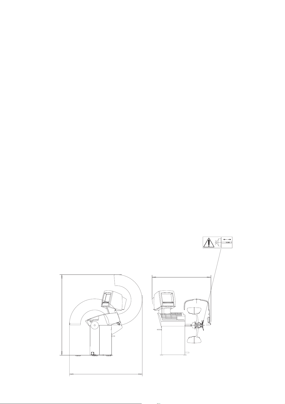
1.3 - OVERALL DIMENSIONS (42" guard)
Fig. 1
1362
1865
1690
I 0202 - 3
GB
Page 4

1.4 - SPECIFICATION
Single phase power supply..............................115 - 230 V 50-60 Hz
Protection class ...............................................IP 54
Max. power consumption.................................1100 W
Monitor ............................................................SVGA 15"
Balancing speed approx..................................180 min
Cycle time for average wheel (14 Kg) ..........6 seconds
Balancing accuracy .........................................0,5 grams
Position resolution ...........................................± 1.4 °
Average noise level .........................................< 70 dB(A)
Distance rim - machine....................................0 - 280 mm (400 mm can be preset)
Rim width setting range ..................................1.5" ÷ 20" or 40 ÷ 510 mm
Diameter setting range ....................................10" ÷ 26" or 265 ÷ 665 mm
Total wheel diameter within guard ...................1067mm (42")
Total wheel width within guard.........................500 mm (42")
Max. wheel weight ...........................................65 Kg.
Min/max. compressed air pressure ................7 ÷ 10 Kg/cm
.........................................................................approx. 0.7 to 1 Mpa;
.........................................................................approx. 7 to 10 BAR;
.........................................................................approx. 100 to 145 PSI.
-1
2
2 - HANDLING AND HOISTING
N.B.: DO NOT HOIST THE WHEEL BALANCER USING DIFFERENT GRIPS
Fig. 2 Fig. 2a
I 0202 - 4
GB
Page 5

3 - COMMISSIONING
3.1 - ANCHORING
The machine can be operated on any fl at non-resilient fl oor.
Make sure that the machine rests solely on the three support points provided (fi g. 2a).
If possible, it is advisable to anchor to the fl oor using relative mounting feet (see fi g. 2a) in the event of
continual use with wheels weighing over 35 Kg.
3.2 - ELECTRICAL CONNECTION
The machine is supplied with a single phase mains cable plus earth (ground).
The supply voltage (and mains frequency) is given on the machine nameplate. It may NOT be changed.
Connection to the mains should always be made by expert personnel.
The machine should not be started up without proper earth (ground) connection.
Connection to the mains should be through a slow acting safety switch rated at 4A amp (230V) or 10
amp (115V) .
3.3 - PNEUMATIC CONNECTION (Versions SE)
For operation of the spindle with pneumatic locking (constant thrust air spring) connect the balancing
machine to the compressed air main. The connection fi tting is located at the back of the machine.
A pressure of at least 7 kg/cm
operation of the release device.
3.4- EXTRA SAFETY DEVICES (Version SE)
- Wheel always locked even when there is pressure failure during the balancing cycle. Always
actuate the unlocking control pedal with the machine stationary in order to avoid stress and
abnormal wear on the adapter.
2
(approx. 0.7 MPa or 7 BAR or 100 PSI) is required for correction
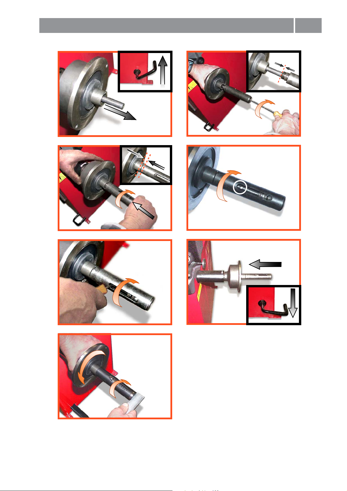
3.5 - ADAPTER MOUNTING
The balancing machine is supplied complete with cone adapter for fastening wheels with central bore.
Other optional fl anges can be mounted once the terminal part is removed (also see enclosed brochures)
N.B. : CAREFULLY CLEAN THE COUPLING SURFACES BEFORE PERFORMING ANY OPERATION.
a) DISMOUNTING THREADED END PIECE
Fig. 3
A
B
a) Back-off screw B and remove threaded end-piece A.
b) Fit the new adapter
I 0202 - 5
GB
Page 6
Mounting
0 mm
SE2
a
1-2 mm
c
b
d
e
g
f
SE2_ 0140
Page 7
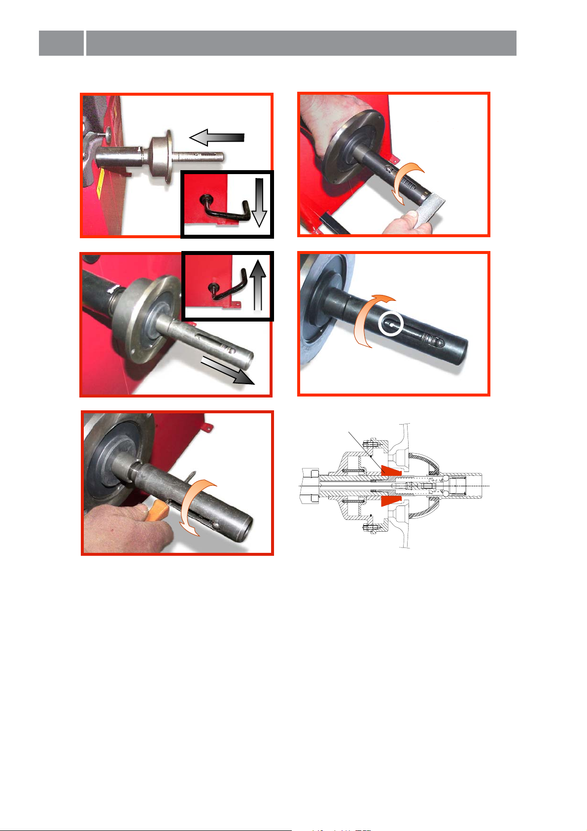
SE2
Dismounting
360°
a
c
b
d
Cone
e
- Quando possibile, centrare le ruote con cono dall'interno (vedi disegno).
- Evitare di usare il manicotto RL con cerchi di ferro.
- Whenever possible, centre the wheels with the cone from the inside (see the drawing).
- Avoid using the RL sleeve with metal rims.
- Lorsque c’est possible, centrer les roues avec le cône de l’intérieur (voir dessin).
- Eviter d’utiliser le manchon RL avec les jantes en fer.
- Wenn möglich, die Räder mit Konus von Innen heraus zentrieren (siehe Zeichnung).
- Bei Eisenfelgen die Verwendung der Muffe RL vermeiden.
- Siempre que sea posible, centrar las ruedas con cono desde dentro (véase dibujo).
- Evitar usar el manguito RL con llantas de hierro.
- Quando possível, centre as rodas com cone pelo lado de dentro (ver fi gura).
- Evite utilizar a luva RL com jantes de ferro.
SE2_ 0140
Page 8

3.6 - GUARD MOUNTING AND ADJUSTMENT
a) Fasten the components to the base as illustrated in specifi c exploded view.
b) The position of the wheel guard when closed can be adjusted with relative screw accessible at the
back. Correct position is the one which keeps the tube exactly horizontal with wheel guard closed.
c) Check that the microswitch is held down when the guard is closed.
d) Adjust the angular position of microswitch control.
3.7 - SPACER WD
When balancing very wide wheels (9”), there is not enough space to turn the distance gauge. To
withdraw the wheel from the machine side, fi t spacer WD on the adapter body and secure it with
the standard issue nuts. When centring the wheel with the cone on the inside, fi t the other cone
as a spacer to obtain spring thrust.
Fig. 4
Spring
DC
WD
Cone
I 0202 - 8
GB
Page 9

4 - CONTROLS AND COMPONENTS
4.1 - BRAKE PEDAL
Fig. 5
4.2 - PNEUMATIC LOCKING PEDAL (Version SE)
Fig. 6
This pedal allows the operator to hold the
wheel when fi tting the counterweights.
It must not be actuated during the
measuring cycle.
This pedal allows releasing the device
fastening the wheel on the adapter.
Do not actuate this pedal during the
machine cycle and/or when adapters
other than the standard cone adapter
are mounted.
The pedal has two stable positions:
top, wheel unclamped; bottom,
wheel clamped.
4.3 - AUTOMATIC DISTANCE AND DIAMETER GAUGE
This gauge allows measurement of the distance of the wheel from the machine and the wheel diameter
at the point of application of the counterweight. It also allows correct positioning of the counterweights on
the inside rim by using the specifi c function (see
allows reading, on the monitor, the position used for the measurement within the rim (For calibration,
see the corresponding section).
The gauge can only be used with the counterweight pincers mounted.
Indication of exact correction weight position ) which
4.4 - AUTOMATIC WIDTH GAUGE (OPTIONAL)
Width gauging is through a SONAR device which measures the distance of the wheel without mechanical
contact, merely by closing the guard and each time a valid measurement has been made with gauge
AUTOMATIC DISTANCE AND DIAMETER GAUGE.
4.5 - AUTOMATIC WHEEL POSITIONING
At the end of the spin, the wheel is positioned according to the unbalance on the outside or else according
to the static unbalance (when selected).
Accuracy is ± 20 degrees.
4.6 - CLOCK CONTROL
The wheel balancer is provided with a clock having a back-up of about one month with the machine
switched off. If the machine remains off for a long period, at the fi rst switch on, check the date and time
(see Clock set-up), adjusting them if necessary.
I 0202 - 9
GB
Page 10

4.7 - KEYBOARD
FUNCTION KEYS: they immediately select corresponding function
Selection of special functions
Confi rm
Starts measuring cycle
Stops measuring cycle
N.B. - Press the buttons with the fi ngers only: never use the counterweight pincers or other
pointed objects.
- When the beep signal is enabled (see section Acustic Signal), pressing of any push button
is accompanied by a “beep”.
I 0202 - 10
GB
Page 11
5 - INDICATIONS AND USE OF THE WHEEL BALANCER
The monitor shows several information and suggests various alternative ways of use to the operator.
This is through various “screens”.
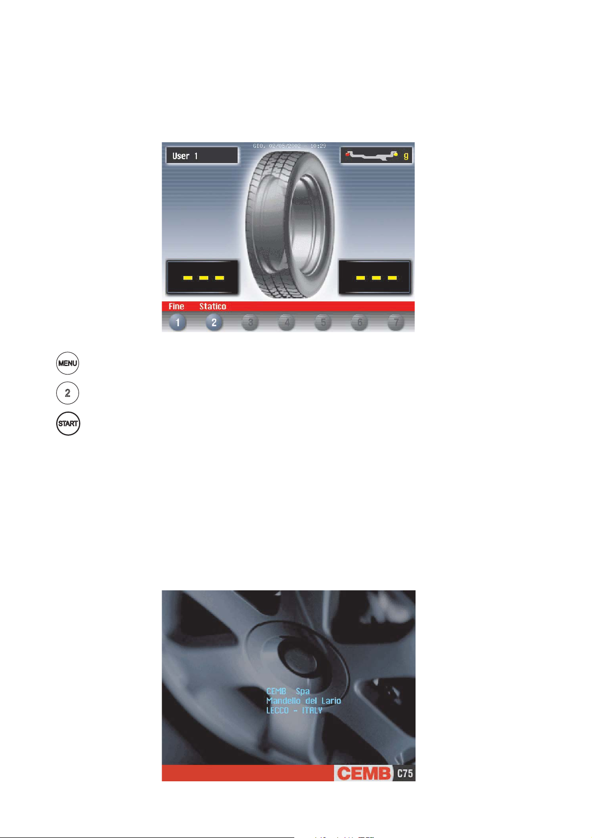
5.1 - INITIAL SCREEN
Buttons enabled
: main functions screen (see Menu access diagram)
: selecting static correction
: balancing spin (see Result of measurement)
Dimensions gauge: when extracted, the Dimensions screen is selected (see Presetting of wheel
dimensions).
If the machine remains on the initial screen for a certain amount of time without being used, the system is
automatically switched to a screen-save. Striking of any key, movement of the wheel of distance
+ diameter gauge will cause automatic switching from the screen-save menu to the initial screen.
5.1.2 SCREEN-SAVE SCREEN
N.B. Name of the wheel balancer’s owner. Can be preset via the monitor.
I 0202 - 11
GB
Page 12

5.2 - MENU ACCESS DIAGRAM
N.B. : - The symbol indicates the presence of a further menu.
- To return to the previous menu, press button
- To return to the initial screen, press button
A
H
Machine setup parameters
Language
Unit of unbalance measurement
Unbalance display threshold
Unbalance display pitch
Spin with guard closing
Screen-saver time
Next
Cancel
Machine setup parameters
Visual eccentricity control
Acoustic Signal
Clock Setting
First harmonic limit
Previous
Cancel
User control
B
selections
User control
Call user
Save user
Optimization
Dimensions
Statistic
Set-up
Special functions
Cancel
PASSWORD : + + +
C
For specialized personnel only
D
Width measurement
Eccentricity measurement
Customer’s personal
Users’ names
Calibration
Special functions
5
Cancel
Calibrations
Distance
Diameter
Width
Cancel
E
Calibrations
Potentiometer
Wheel balancer self-calibration
Ambient temperature
Wheel balancer self test
Cancel
F
I 0202 - 12
GB
Page 13

5.3 - PRESETTING OF WHEEL DIMENSIONS
5.3.1 AUTOMATIC PRESETTING
(see also
CORRECTION MODE)
INDICATOR
L.T. function enabled
(see Buttons
Enabled)
The screen appears upon removing the distance + diameter gauge.
The “dimension acquired” message is indicated by the correction weight symbol, which changes from
blue to red.
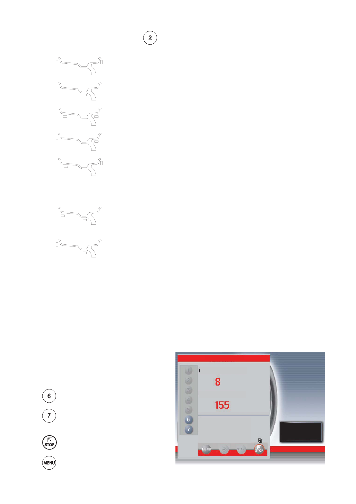
- INNER SIDE WEIGHT: Using the special grip, move the end of the gauge against the rim in position:
a) Sprung weight : in one of the positions A/B indicated in fi gure 8.
Fig. 8
INDICATOR: Width
Sonar function
enabled
POS A
b) Adhesive weight: in the position indicated below
Fig. 9
Position of
adhesive
weight
- Hold the gauge in position for at least 2 seconds.
If the acoustic signal is enabled (see Acoustic signal), the acquisition of the dimensions is accompanied
by a “beep”. Manual setting is possible using the buttons as described in Manual setting.
N.B.: Use pushbuttons
and to select the type of weight to apply (see CORRECTION MODE)
POS B
I 0202 - 13
GB
Page 14

- OUTER SIDE WEIGHT:
a) Weight outside the rim
Wheel width measurement is carried out by the SONAR by closing the protection system after a valid diameter
and distance measurement. If the width measured is incorrect (out of range), the following message appears:
"Sonar measure is out of range"
" F1 = repeat"
" F2 = manual set-up"
(If the width sonar is not used, see "
MANUAL PRESETTING“)
b) Hidden inside adhesive weight
After the measurement performed for the FI inner side, as indicated in fi g. 10, pull out the gauge again to
store the data for the FE outer side; choose position A or B (fi g. 8) at your choice. Keep this position for at
least 2 seconds. The counterweight symbols change colour.
When the acoustic signal is enabled (see
ACOUSTIC SIGNAL), the acquisition is accompanied by a “beep”.
Position of
adhesive
weights
After having detected the dimensions, use the
key to indicate the type of correction selected for
the inner side.
The following buttons are enabled:
Management of save user recall
/
Selection of spring or adhesive weight for inner/outer application.
/
The L.T. key (LIGHT TRUCK) used to improve the dimensional calibration of large-
diameter wheels such as off-road, trucks, wheels which protrude signifi cantly from the
rim. Press the L.T. key, after distance measurement, immediately before lowering the
guard for Width Measurement. The option is disengaged at the end of current Width
Measurement.
Selecting the manual dimension presetting screen
/
Return to initial screen
Balancing run
I 0202 - 14
GB
Page 15
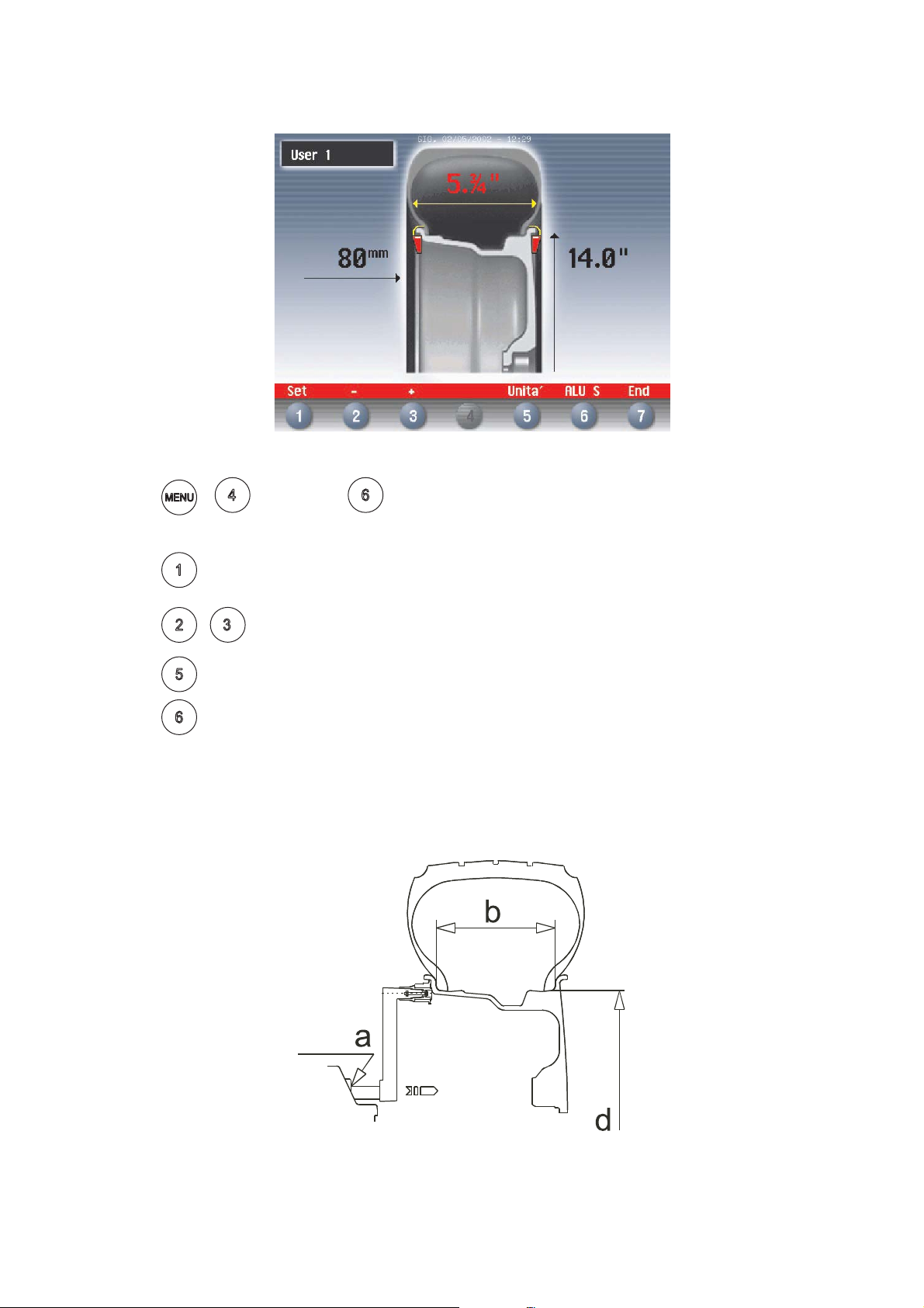
5.3.2 - MANUAL PRESETTING
If necessary, the dimensions can be inserted or edited in manual mode as follows:
- press
screen (which can be reached by pulling out the distance + diameter gauge).
- press
- press
- press
- press
Defi nition of dimensions for correction using spring weights:
d = DIAMETER: Preset the nominal diameter stamped on the rim.
b = WIDTH: Preset the nominal width indicated on the rim.
a = DISTANCE: Preset the distance of the inside of the wheel from the machine, after measuring
+ or else press from the Dimensions in automatic mode
to select the dimension to be preset (red).
/ to preset the required value.
to change unit of measurement.
to preset the dimensions for the ALU-S correction mode
it with relative gauge as described in fi g. 8.
Fig. 10a
In the event of correction type other than standard (spring weight), follow the instructions on the screen
for correct detection of dimensions.
I 0202 - 15
GB
Page 16
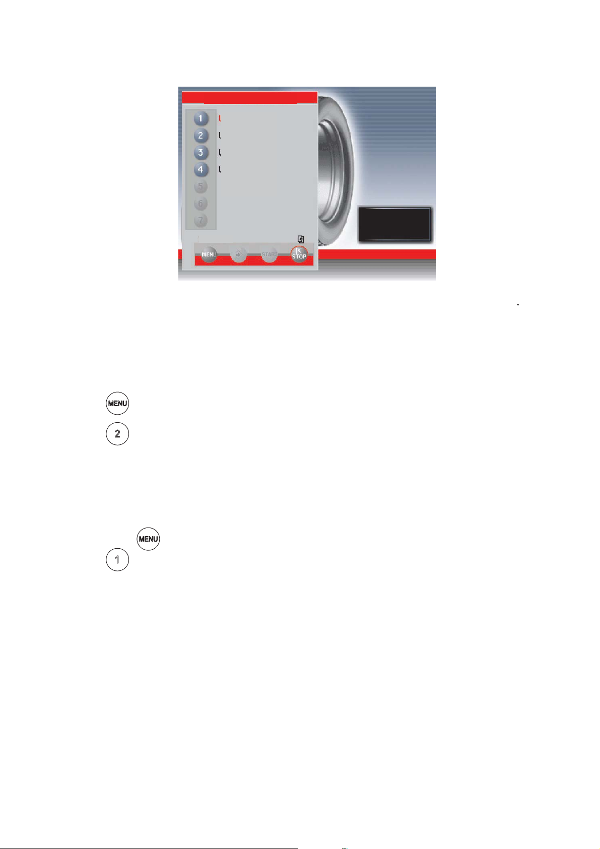
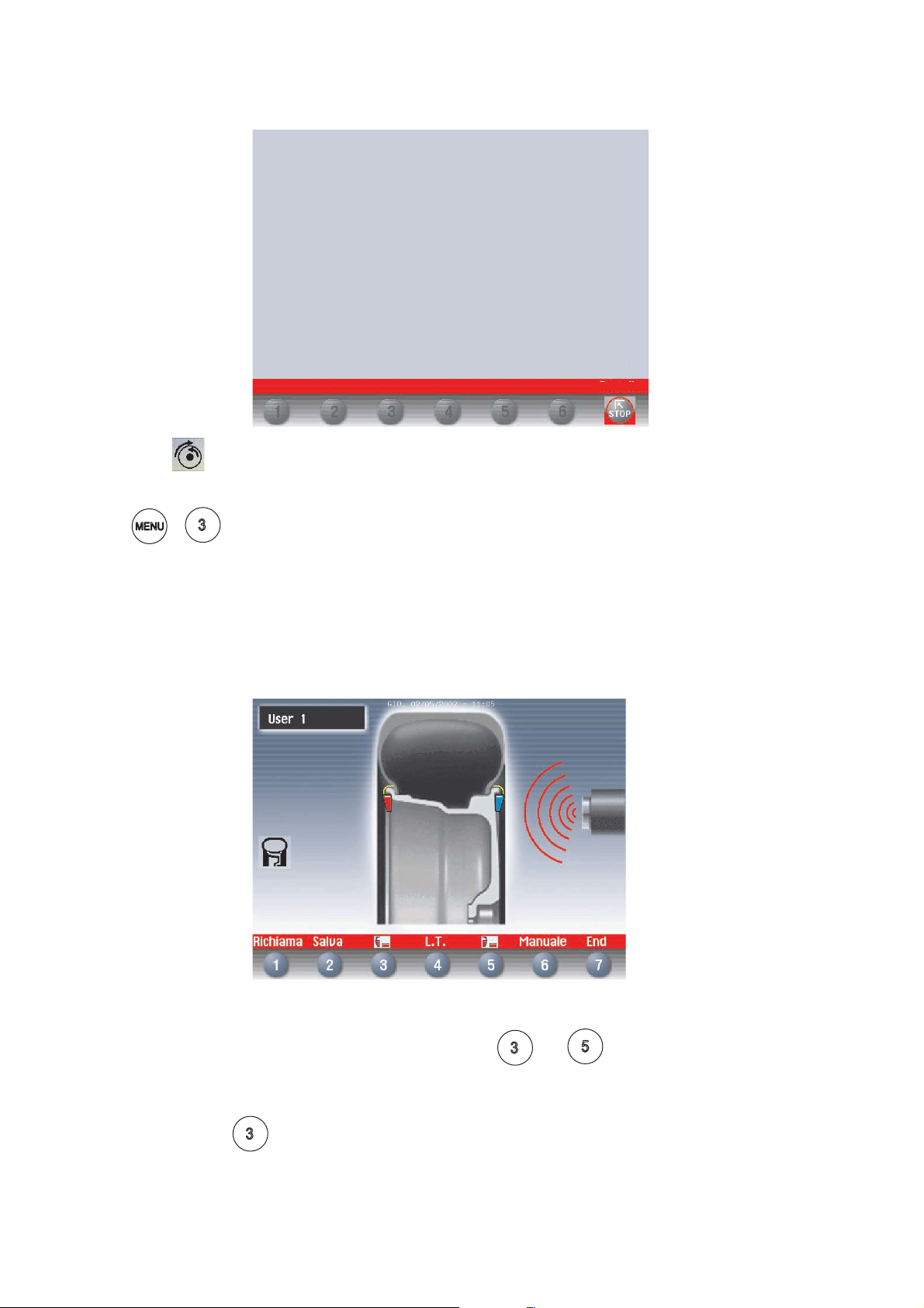
5.4 - USER CONTROL
User memorization
User 1
User 2
User 3
User 4
Cancel
The wheel balancer can be used simultaneously by 4 different users who, through a simple sequence, can
memorize their work condition and call it when needed. The users’ names can be memorized (Presetting
the customer and user name).
5.4.1 - USER MEMORIZATION
- Preset the dimensions correctly according to the procedures already described in sections
Automatic presetting.
- Press
- Press
; the “MENU” window appears on the monitor.
; a window appears with the list of available USERS. The current user is displayed in red.
- Press the number corresponding to the required USER. The system returns to the initial screen
automatically.
5.4.2 - TO CALL USER
- Perform a measuring spin with any dimensions.
- Press button
- Press
: a window appears with the list of available USERS. The current user is displayed in red.
; the “MENU” window appears on the screen.
- Press the number corresponding to the required USER. The system automatically returns to the initial
screen with recalculation of the unbalance values on the basis of the effective dimensions of the USER
called.
N.B. - The dimensions memorized as USER are lost when the machine is switched off.
- The USER control is also valid for the ALU-S dimensions.
- The current USER is always displayed in the Measurements and Dimensions screens.
I 0202 - 16
GB
Page 17
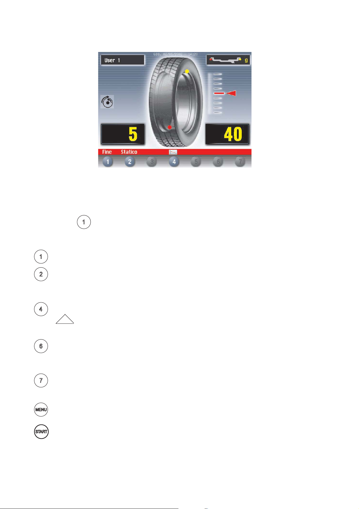
5.5 RESULT OF MEASUREMENT
After performing a balancing spin, the unbalance values are displayed as well as arrows useful for
positioning the point of application of the correction weight. After positioning the wheel, apply the weight in
the 12 o’clock position. When the beep signal is enabled (see section ACUSTIC SIGNAL), reaching of the
correction position is accompanied by a “beep”.
If the unbalance is less than the chosen threshold value, the “OK” appears instead of the unbalance value
to indicate, on that particular side, the wheel is in tolerance; the residual unbalance can be displayed by
pressing button
The following buttons are enabled:
Display of residual unbalance
Selection of correction mode (STATIC/DUAL SURFACE). When the mode is changed, the
unbalance values are recalculated automatically on the basis of the previous spin.
Eccentricity measurement graph (option). The symbol above the key is fl anked by the symbol
harmonic limit ).
Indication of the longitudinal position of the unbalance (Indication of exact correction weight
position) is enabled
!
Split control for splitting of unbalance over presettable components (“SPLIT” control). Button
only enabled in STATIC or ALU S correction.
with an accuracy of 0.5 g (0.1 oz).
if the harmonic eccentricity exceeds the limit indicated by the setup parameters (First
For selection of special functions
Balancing spin.
N.B. If the machine remains on this screen without being used for more than the time preset in the Setup
parameters (6), the screen automatically returns to the screen-save.
I 0202 - 17
GB
Page 18
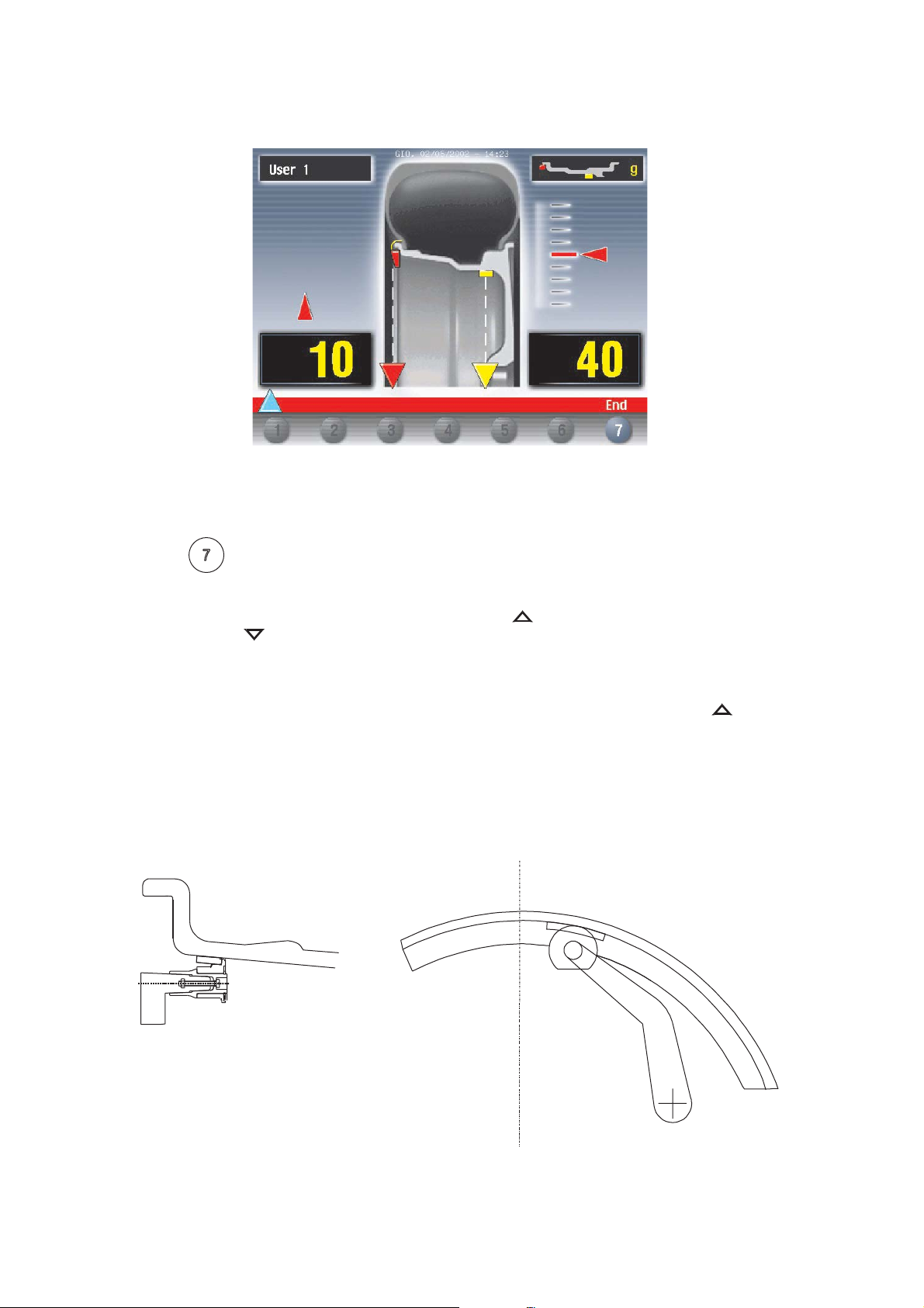
5.5.1 - INDICATION OF EXACT CORRECTION WEIGHT POSITION
It is possible use this function in the event of correction of the external side using an adhesive weight
placed inside the rim.
This function allows cancelling approximations in the mounting of counterweights with consequent
reduction of the residual unbalance.
- Press button
from the Measurements screen.
- Pull out the rim distance+diameter gauge in position A, fi gure 8. Approach of the weight to the
correction position is indicated by a moving coloured arrow [
- When a fi xed arrow [
] is reached, rotate the wheel to correction position (FI or FE) and apply
].
the counterweight by turning the tip of the gauge towards the outside, into the position in which the
pincers touches the wheel. Compensation is made for the fact that the weight application position is
no longer at 12 o’clock (fi g. 11).
When the acoustic signal is enabled (see
ACOUSTIC SIGNAL), the reaching of a fi xed arrow [ ] is
accompanied by a “beep”.
Fig. 11
I 0202 - 18
GB
Page 19

5.5.2 - “SPLIT” CONTROL
The SPLIT function is only possible in the case of static unbalance or ALU-S on the outside. It serves for
concealing any stick-on unbalance correction weights behind the rim spokes.
TO PRESET THE NUMBER OF RIM SPOKES
-From the STATIC or ALU-S measurement screen, press
- A window appears on the display indicating the currently preset number of spokes.
- Set the required number of spokes in the range 3 to 12 by pressing
- press to confi rm the presetting.
- Bring a spoke to the 12 o’clock position.
- press
The ALU-S unbalance on the inside does not vary while as regards the STATIC unbalance and that
ALU-S on the outside:
- Gradually turn the wheel until an unbalance value appears.
- Apply an adhesive weight of the value indicated on the screen for the outside or STATIC, behind
- Again turn the wheel until a new unbalance value appears.
- Apply an adhesive weight of the value indicated on the screen for the outside or STATIC, behind
- Perform a spin to check for correct wheel balancing.
N.B.: When SPLIT is enabled, the icon
; the Measurement Screen reappears with the unbalance values already split.
the spoke in the 12 o’clock position.
the spoke in the 12 o’clock position.
appears to the left of the screen.
;
and
I 0202 - 19
GB
Page 20
5.5.3 - UNBALANCE OPTIMIZATION
UNBALANCE OPTIMIZATION
- CAUTION!! The previous spin should have been performed
with the currently mounted wheel.
- Indicate the rim-adapter position with a reference mark
in order to remount the rim on the adapter in the same position.
- Remove the wheel from the wheel balancer.
- Turn the tyre on the rim by 180°.
- Remount the wheel on the wheel balancer positioning
the reference mark of the rim with that of the adapter.
- Close the guard and press the (START) push button.
The symbol is displayed automatically for static unbalance exceeding 30 grams (1.1 oz). The
program allows reducing the total unbalance of the wheel by compensating, when possible, the unbalance
of the tyre with that of the rim. It requires two spins with rotation of the tyre on the rim in the second spin.
Cancel
Press
+ after a fi rst spin and follow the instructions appearing on the monitor.
5.5.4 - CORRECTION MODE
After having performed automatic measurement of the inner side, it is possible to place
the correction weights as required by pressing pushbuttons
and .
N.B.: In the event of automatic measurement of both sides, if the difference between the inner and outer
diameters is greater than or equal to 2”, the system sets the inner side spring weight. To modify this
presetting, press the
I 0202 - 20
GB
button. The external side may only be “adhesive”.
Page 21
ALU S :
To display static unbalance, press the
button on the measurement screen (for ALUS static,
the inner side diameter is always considered).
Possible types of correction:
Balancing of steel or light alloy rims with application of clip-on
weights on the rim edges
The STATIC mode is necessary for motorcycle wheels or when it is not
possible to place the counterweights on both sides of the rim.
Balancing of light alloy rims with application of adhesive weights on
the rim shoulders.
Combined balancing: adhesive weight on the outside, clip-on weight
inside
Combined balancing: clip-on weight outside and adhesive
weight inside.
Balancing of alloy rims with hidden application of the adhesive
weight on the outside.
Combined balancing: clip-on weight inside and adhesive hidden
weight outside (Mercedes).
5.5.5 - TO CANCEL STATIC UNBALANCE
This function can be selected from the Setup screen. It serves for optimizing the residual unbalance by
correcting a wheel with standard counterweights in steps of 5 grams (1/4 oz.).
Thanks to this particular function, the position and best correction value are calculated in order to cancel
the static unbalance: the main cause of the vibrations which can be felt inside the car.
5.6 - STATISTICS
DAILY N° OF RUNS:
Indicates the number of runs performed as from switching on the machine. Such parameter is automatically
reset after switching the machine off.
TOTAL N° OF RUNS:
Indicates the number of runs performed as from
the last resetting of such counter. This parameter
remains memorized also when the machine is
switched off.
The following push buttons are enabled:
: serves for resetting the daily number of
runs
: serves for resetting the total number of
runs. Requires correct setting of a
password.
: for returning to previous screen (MENU)
: for returning to Measurement screen
STATISTICS
Daily N° of runs
Total n° of runs
Resetting daily n° of runs
Resetting total n° of runs
Cancel
I 0202 - 21
GB
Page 22
5.7 - WHEN AND WHY MATCHING
The C75 software associated with eccentricity measurement is a powerful tool for determining the need
to perform relative rotation between the rim and tyre in order to reduce the eccentricity of the wheel down
to acceptable limits. The principle adopted is based on the consideration that a rim with acceptable
tolerance, mounted with an acceptable tyre, can statistically generate a total eccentricity which is not
acceptable but can be improved by matching.
Generally speaking, rim measurement is not necessary, accurate or useful because:
• To measure the rim it is necessary to remove the tyre. There can by coarse errors on the outside
(e.g. aluminium wheels!)
• The two rim sides can be eccentric in a very different way. Therefore to which one to make reference?
What is the effect on the tyre mounted?
• To improve the eccentricity of a wheel, the rim should be eccentric, to compensate the tyre. And
viceversa.
• If after a rotation by 180° of a wheel, the value is still out-of-tolerance, either the tyre or rim are too
eccentric: One of the two must be replaced!
wheel
Example 1
Ideal wheel
rotation axle
SOLUTION:
Rotate the tyre on the rim by 180°
Ideal wheel
rim
tyre
Eccentricity of the wheel is
excessive, due to an acceptable
rim or tyre but randomly placed in
an “unfortunate” relative position.
RESULT:
wheel eccentricity 0.3 - 0.4 mm
(in tolerance)
wheel
Rim + 0.8 mm
Tyre + 0.6 mm
Wheel + 1.3 mm
Example 2
rotation axle
I 0202 - 22
GB
rim
Rim + 0.8 mm
Tyre - 0.6 mm
Wheel + 0.3 mm
tyre
Eccentricity of the single items
has been compensated.
The wheel is acceptable.
Page 23

Ideal wheel
wheel
Example 3
rotation axle
SOLUTION:
Rotate the tyre on the rim by 180°
rim
tyre
RESULT:
no improvement is obtained
Rim 0 mm
Tyre + 1.2 mm
Wheel + 1,2 mm
Eccentricity of the wheel cannot
be compensated by the rotation
because the rim is perfect!
5.7.1 - PRESETTING OF TOLERANCE ON THE MACHINE
There is no general rule concerning acceptability of an eccentricity value . As a fi rst approximation we
consider it correct to use a threshold of 1 to 1.5 mm. The E/ECE/324 standard prescribes 1.5 mm as
max. eccentricity of a rebuilt tyre.
5.7.2 - VALUE OF STATIC UNBALANCE, CORRELATED WITH ECCENTRICITY
Clear indication is given in the Measurement screen of both the value and position of the static unbalance
as well as the eccentricity. In fact, it is interesting to check the correlations of the two values, above all of
the two positions. When the two positions have a similar angle (± 30° one from the other), there is a clear
sign that an eccentricity is present which can be compensated by matching.
5.7.3 - VALUE OF UNBALANCE CORRESPONDING TO ECCENTRICITY
For user’s reference, the centrifugal force is calculated corresponding to a certain speed, compared to
the force generated by the eccentricity present on the tyre (calculated with an approximate average
elastic constant).
I 0202 - 23
GB
Page 24

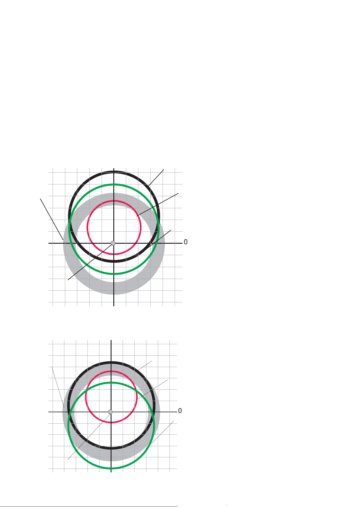
5.8 - ECCENTRICITY MEASUREMENT (OPTIONAL)
The much enlarged fi gures show the outer tyre surface and axis of wheel rotation.
Fig. A - shows measurement of the total Peak-to-Peak eccentricity defi ned as maximum radial deviation
of the tyre surface.
Fig. B - shows measurement of the eccentricity of the
1st harmonic, i.e. the eccentricity of that circle which
Fig. A
“recopies” the tyre shape, by averaging the local
deviations of the tyre from the round shape.
Obviously the P.P. measurement is normally greater
than that of the 1st harmonic. Tyre manufacturers
normally supply two different tolerances for the
two eccentricities.
At the end of the balancing spin it is possible to automatically measure the eccentricity of the
tyre through the SONAR sensor installed on the guard. The sensor should be positioned by hand
in front of the tyre tread.
Fig. B
GRAPH 1 - (yellow)
GRAPH 2 - (red)
GRAPH 1 : represents the actual Peak-to-Peak eccentricity.
GRAPH 2 : represents the eccentricity of the 1st harmonic. For a wheel in optimum conditions, such
graph should approach a straight line.
While rotating the wheel, the screen cursor indicates the current value, with the stage referred to the
eccentricity measurement sensor. Press pushbutton
to access a panel where important information
about eccentricity is displayed, such as the imbalance effect which the fi rst eccentricity harmonic measured
may exert at an average speed of 120 km/h.
I 0202 - 24
GB
Page 25
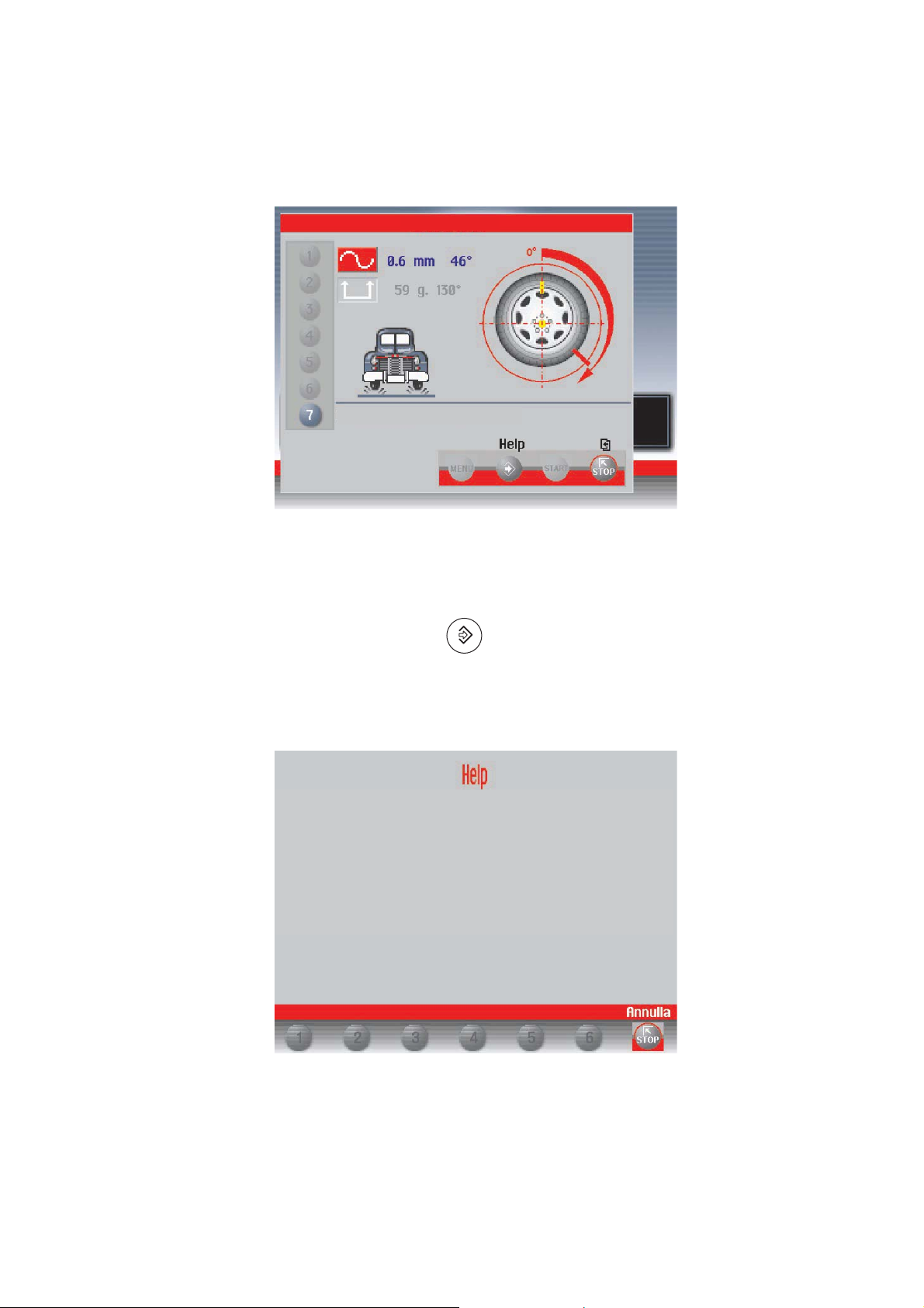
N.B.:
If the fi rst harmonic value is higher than the limit indicated by setup parameters (see First harmonic
limit), at the end of the eccentricity measurement, the following window appears:
CAUTION
Eccentricity display
In this case, it is advisable to rotate the tyre on the rim by 180° in order to reduce the eccentricity
value measured.
For more detailed information, press pushbutton
.
Before balancing the wheel, it is advisable to rotate
the tyre on the rim by 180° in order to educe the
eccentricity measured.
CAUTION! The current eccentricity of 1.0 mm gives
rise to a force more or less equivalent to that generated by an imbalance of 33.2 gr at a speed of 120
km/hour.
“Note for models fi tting 42” wheelguard: eccentricity measure is valid for tyre with max. 1000 mm Ø”
I 0202 - 25
GB
Page 26

6 - SETUP
(see Diagram showing access to the menus)
The Setup screen provides the user with many possibilities required for presetting the machine according to
his own requirements. Such settings remain unaltered even when the machine is switched off.
The following buttons are enabled:
: return to previous window
: return to Measurement screen
from
to : for selection of the parameter.
6.1 - LANGUAGE
This function allows selecting the language to be used for displaying descriptive and diagnostic messages
regarding machine operation.
6.2 - UNIT OF UNBALANCE MEASUREMENT
It is possible to select whether to display the unbalance values expressed in grams or ounces.
6.3 - UNBALANCE DISPLAY THRESHOLD
This consists of the unbalance threshold below which the wording “-OK-” appears on the screen at the end
of the spin instead of the unbalance; the presettable values vary according to the unit of measurement
selected.
6.4 - UNBALANCE DISPLAY PITCH
This represents the display pitch of the unbalance and varies according to the unit of measurement selected.
The selection “5 g” (1/4 oz) enables display of the correction values on both sides such as to bring
the static unbalance to 0 (theoretical). It is recommended to preset this function as standard use of
the machine as it improves the balancing quality. The computer makes a complex calculation which
allows cancelling the residual static unbalance by varying the value and position of the counterweights
fi xed in steps of 5 grams (1/4 oz).
6.5 - SPIN WITH GUARD CLOSED
When “ON” is selected the automatic start of the spin is enabled when the guard is closed.
6.6 - SCREEN-SAVER TIME
When the machine remains unused for longer than the time preset with this function, the processor
automatically returns to the Initial screen. Preset the time in seconds.
6.7 - VISUAL ECCENTRICITY CHECK
At the end of wheel acceleration, as soon as the motor is disengaged, the guard can be opened for visual
control of any wheel eccentricity as the rotation speed gradually drops.
Do not strike the wheel during the entire deceleration stage; to brake the wheel, close the guard. However,
avoid using the brake as far as possible because this may compromise unbalance measurements. The
unbalance values measured are only displayed when the wheel has come to a standstill.
This function is active for only one machine run.
6.8 - ACOUSTIC SIGNAL
When “ON” is selected, the sending of an acoustic signal (beep) is enabled in the following cases:
- when any push button is pressed;
- when dimensions are acquired in automatic mode;
- when the correct angular position for weight application is reached in the Measurement screen;
- when the correct angular position for weight application is reached in the Position Repeater screen.
6.9 - TO SET THE CLOCK
Serves for correct setting of the date and time: follow the instructions on the screen.
6.10 - FIRST HARMONIC LIMIT
The fi rst harmonic limit beyond which it is felt suitable to rotate the tyre on the 180° rim. Recommended
Limit = 1.2 mm. If a 1st harmonic higher than the set limit is measured, a window appears on screen to
indicate the need to rotate the tyre of the rim.
I 0202 - 26
GB
Page 27

- CAUTION -
7 - SPECIAL CALIBRATIONS AND FUNCTIONS
(See MENU ACCESS DIAGRAM )
In order to gain access to the “Reserved Calibrations and functions” it is necessary to enter a password.
Any incorrect operation within the functions described below could impair the operation of the wheel
balancing machine. Unauthorized use will cause cancellation of the warranty on the machine.
7.1 - ENABLING OF WIDTH MEASUREMENT
This function enables/disables automatic width measurement with SONAR or contact device; always
select “SONAR”.
7.2 - PRESETTING THE CUSTOMER AND USER NAME
The machine can be customized by presetting:
a) The name appearing on the Initial screen (screen-save).
b) The name of 4 different machine users (USER NAME).
An “ideal” keyboard appears on the monitor with the set of characters available for composition of
the wordings.
The Customer’s name consists of three lines, each max. 30 characters.
The USER NAME consists of a wording max. 15 characters.
7.3 - ENABLING OF ECCENTRICITY MEASUREMENT
Enables/disables measurement of the tyre eccentricity during an unbalance measurement spin.
7.4 - CALIBRATIONS
When is pressed from the Special Functions menu, access is gained to the Calibration menu.
7.4.1- GAUGE CALIBRATION
Select the gauge to be calibrated and follow the instructions appearing on the monitor.
N.B.:
- In the diameter gauge calibration it is highly important to position the gauge correctly as shown in fi g.8.
- In the width gauge calibration it is necessary to enter one dimension which can be measured as
follows:
A - GAUGE “ZERO” DISTANCE
SONAR “ZERO” DISTANCE
Fig. 13
0
I 0202 - 27
GB
Page 28

7.4.2 - WHEEL BALANCER CALIBRATION
For calibration of the machine, proceed as follows:
- Use a medium-sized metal wheel. Example: 6" x 14" (± 1")
- Preset the wheel dimensions with GREAT CARE.
- Follow the instructions appearing on the monitor.
7.4.3 - AMBIENT TEMPERATURE
Ambient temperature is important for correct use of the sonars. Set the average temperature of the area
where the wheel balancer is installed.
7.4.4 - SELF-DIAGNOSTICS
An automatic self-diagnostics cycle is provided for easier trouble shooting. At the end of the selfdiagnostics cycle, several parameters are displayed which are useful for the Technical Service Department in order to identify machine faults.
: returns to previous menu.
7.4.4.1 - TO CHECK THE ENCODER
When the spindle is rotated:
- the angular position “POS” should vary from 0 to 128;
- the wording “UP” should appear when rotated clockwise and “DOWN” when rotated in the opposite
direction.
Check for correct operation of the diameter
gauge; the number
Encoder check
tyre
increases when the
gauge is rotated
outwards
Check for correct operation of the distance gauge;
the number increases
when the gauge is pulled
out.
Check of the eccentricity sonar (option):
the number decreases when a surface
is approached to the sonar
In the event of failure or faulty operation of the wheel balancing machine, notify the Technical Service
of all the parameters displayed.
Check of the width
sonar: the number
decreases when a
surface is approached
to the sonar
I 0202 - 28
GB
Page 29

7.5 CONTROL OF SERIAL OUTPUT RS232C (OPTION)
This option enables/disables the sending of the measured unbalance and phase values to serial output
RS232C.
Transmission speed = 9600 baud
Data format = 7 bit Start
7 bit Data
1 bit Even parity
1 bit Stop
At the end of each unbalancing measuring spin, the balancing machine enables the RTS signal, then places
the "$" character on standby to be able to transmit the data; all functions remain on hold until data transmission
is enabled, at the end of which the RTS signal is reset to the inactive state.
The items of data transmitted via serial line are in ASCII format and are separated between each
other by the <cr> character (0x0d).
Sending sequence is as follows:
- 00000 <cr>
- Value of correction weight, left side <cr>
- Correction phase, left side <cr>
- Value of correction weight, right side <cr>
- Correction phase, right side <cr>
The fi rst 5 zero bytes represents the start of transmission message. The correction values are expressed
in grams, in steps of .1 gram.
The phase values are expressed in degrees, in the range 0% 359
See specifi c computer board on exploded drawings.
I 0202 - 29
GB
Page 30

8 - ERRORS
Error N°
Guard open
ERROR MEANING
1 No rotation signal. Could be due to a faulty position transducer, or to the
motor failing to start, or to something preventing the wheel from turning.
CAUTION
2 During the measurement spins, wheel speed had dropped below 60
r.p.m. Check encoder functioning (see
and repeat the launch.
3 Error in the mathematical calculations, most probably caused by incorrect
carrying out of the self-calibration. Repeat the self-calibration. Wheel
unbalance too high.
4 Motor turning in opposite direction.
5 Guard open before start of spin.
7/8/9 Fault in the machine setup parameters.
Check for correctness of the basic setup parameters and repeat the
machine calibration. Contact Technical Service.
11 Speed too high for the measurement.
12/13/14 Overfl ow of counters used for the measurement. Check encoder functio
ning (see To check the encoder). Contact Technical Service.
15/16/17/18 Contact Technical Service.
20 Wheel stopped before having positioned it.
To check the encoder)
30 Error in clock control on the screen.
40 ÷ 53 Error in control of eccentricity measurement graphs
I 0202 - 30
GB
Page 31

9 - ROUTINE MAINTENANCE
Before performing any action on the plant, isolate the electrical power supply.
9.1 - TO REPLACE THE FUSES
Remove the weight holder shelf to gain access to the power supply board where the 4 fuses are
located (see Exploded Drawings). If fuses require replacement, use ones of the same
current rating. If the fault persists, contact Technical Service.
NONE OF THE OTHER MACHINE PARTS REQUIRE MAINTENANCE.
10 - RECOMMENDED SPARE PARTS LIST
(For further details, see exploded drawings)
CODE DESCRIPTION
020600503 Bearing 6005-2Z dia. 25/47/12
181198630 Spring 19863P
080077007 Rigid belt Poly V - TB2 - 770 - 7 Vee’s
67M38954C Position pick-up board with cable
182245870 Spring, brake lever 24587P
05PR52921 LEXAN panel
182185750 Spring, rim distance gauge
67M48208A Power board with 2 relays/ 2 sonar
681002000 Fuses DM 5x20 - 2A
511242101 Oscillating switch 16A
86SC54002 Computer board
86SB38988 Cable, automatic rim distance gauge
86SB36493 Cable, automatic diameter gauge
86SB50843 Width sonar (optional)
86SB38585 Cable with microswitch for 42” protection
801100164 Monitor 15" SVGA
SPECIAL PARTS FOR 230V MACHINES
501054213 Single phase motor BIMA 230V/50-60 Hz -0.18Kw 63/B3 - 4p.
86SZ50844 Complete power board
611000314 Braking transformer 30VA 230 - 0/50
568001458 Capacitor 14MF 450 V FASTON screw M8
611051827 Power transformer 40VA
SPECIAL PARTS FOR 115V MACHINES
502054114 Single phase motor BIMA 115V/50-60Hz- 0.18Kw - 63/ B3 - 4p
86SZ50845 Complete power board
611000313 Braking transformer 30VA 115-0/25
568002557 Capacitor 25MF 450V FASTON screw M8
611051828 Power transformer 40VA
SPECIAL PARTS FOR SPINDLE SE
020600702 Bearing 6007 - LLB/2AV1 dia. 35/62x14 Front.
020600703 Bearing 6007 - 2Z dia. 35/62x14 Rear.
18FP29329 Air spring 115 kg. stroke 75 mm.
16FB42177 Coil valve
18FB42639 Spring, pneumatic pedal
SPECIAL PARTS FOR EMS SONAR (OPTION)
86SB50847 Ems sonar
I 0202 - 31
GB
Page 32

11 - SETTING MONITOR COLOURS
Fig. 14
a) Remove the clip-fi tted control panel by leve
ring on the short side (caution: do not
damage the fl at connection cable)
The window on the base provides access to the
monitor control buttons for colour settings
b) LUMINOSITY: Press 1 or 2 and set
~ 80% (always with 1 & 2)
c) CONTRAST: Press 4-5 and set 100%
Press 3 (MENU) to exit
d) COLOURS: Press 3
- Press 4 twice selecting
1 2 3 4 5
NOTE: this description is valid for the DAEWOO 15” monitor, code 801100164. For different models,
make adjustments so that “red” on the monitor is as similar as possible to the CEMB “red” on the base.
in the window
- Press 3 until "USER" is selected
- Press 2 and set 100% with 4 - 5
on the blue bar
- Press 2 again and set 100%
on the green bar
- Press 2 again and set 100%
on the red bar
R
G B
I 0202 - 32
GB
 Loading...