


TECHNICAL GUIDE
ELECTRONIC CASH REGISTER
TROUBLE SHOOTING GUIDE
230ER
INDEX
HARD KEY CODE TABLE (230ER)
The HARD KEY CODE TABLE which written in our service manual is for 190ER. 230ER table is as follows;
FEED |
34 |
37 |
|
7 |
8 |
9 |
|
16 |
20 |
|
24 |
27 |
|
|
|
|
|
|
|
|
|
|
|
|
|
30 |
33 |
36 |
|
4 |
5 |
6 |
|
15 |
19 |
|
23 |
26 |
|
|
|
|
|
|
|
|
|
|
|
|
|
29 |
32 |
35 |
|
1 |
2 |
3 |
|
14 |
18 |
|
22 |
25 |
|
|
|
|
|
|
|
|
|
|
|
|
|
28 |
31 |
C |
|
0 |
10 |
11 |
|
13 |
17 |
|
21 |
|
|
|
|
|
|
|
|
|
|
|
|
|
|
1. 230ER
Checking flowchart
|
|
|
Mode switch ON |
|
|
|
|
|
|
|
|
|
|
|
||
|
|
|
|
|
|
|
|
|
|
|
|
|
|
|
|
|
|
|
|
|
|
|
|
|
|
|
|
|
|
|
|
|
|
|
|
|
ECR is working OK? |
|
|
|
|
|
|
|
|
|||||
|
|
|
|
|
|
|
|
|
|
|
|
|
|
|
|
|
|
|
|
|
No |
|
|
No |
|||||||||
|
|
|
|
|
|
|
|
|
|
|
|
|
||||
|
|
|
Power supply and PWD signal are OK? |
|
|
|
See A (Page 2) |
|||||||||
|
|
|
|
|
|
|||||||||||
|
|
|
|
Yes |
|
No |
|
|
|
|
||||||
|
|
|
|
|
|
|
|
|
|
|
|
|
|
|
See B (Page 3) |
|
|
|
|
Printer initialization is OK? |
|
|
|
|
|||||||||
|
|
|
|
|
|
|
||||||||||
|
|
|
|
|
|
|
|
|
|
|
|
|
|
|
|
|
|
|
|
|
Yes |
|
|
|
|
|
|
||||||
|
|
|
|
|
|
|
|
|
No |
|
|
|
See C (Page 4) |
|||
|
|
|
Display 0.00 is OK? |
|
|
|
|
|||||||||
|
|
|
|
|
|
|
|
|
|
|||||||
|
|
|
|
|
|
|
|
|
|
|
||||||
|
|
|
|
|
|
|
|
|
|
|
|
|
|
|
|
|
|
|
|
|
Yes |
|
|
|
|
|
|
||||||
|
|
|
|
|
|
No |
|
|
|
|
|
|
||||
|
|
|
Key input is OK? |
|
|
|
|
|
|
|
|
See D (Page 6) |
||||
|
|
|
|
|
|
|
|
|
|
|
|
|||||
|
|
|
|
Yes |
|
|
|
|
|
|
||||||
|
|
|
|
|
|
|
|
No |
|
|
|
|
|
See E (Page7) |
||
|
|
|
Transaction is OK? |
|
|
|
|
|
|
|
||||||
|
|
|
|
|
|
|
|
|
|
|
||||||
|
|
|
|
|
|
|
|
|
|
|
|
|
|
|||
|
|
|
|
Yes |
No |
|
|
|
|
|||||||
|
|
|
|
|
|
|
|
|
|
|
|
|
|
|
||
|
|
|
Receipt printing is OK? |
|
|
|
|
|
|
See F (Page8) |
||||||
|
|
|
|
|
|
|
|
|||||||||
|
|
|
|
|
|
|
|
|
|
|
|
|
||||
|
|
|
|
Yes |
|
|
|
|
|
|
||||||
|
|
|
|
|
|
No |
|
|
|
|
|
See G (Page 8) |
||||
|
|
|
Drawer is open? |
|
|
|
|
|
|
|||||||
|
|
|
|
|
|
|
|
|
||||||||
|
|
|
|
|
|
|
|
|
|
|
|
|||||
|
|
|
|
|
|
|
|
|
|
|
|
|
|
|
|
|
- 1 -
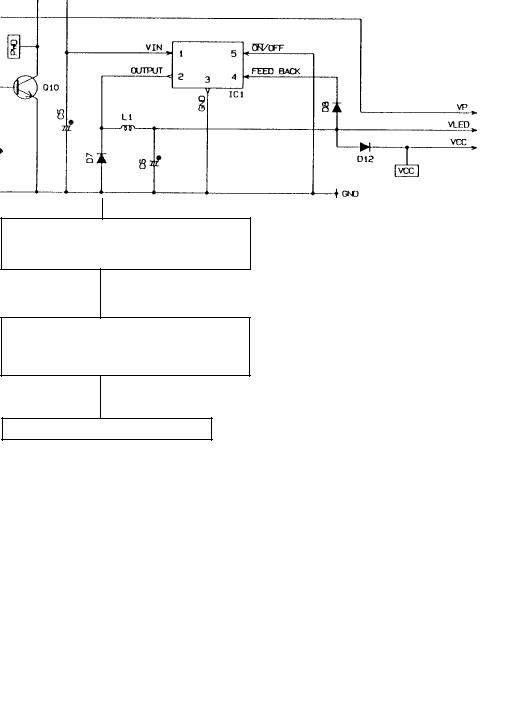
A. Power supply and PWD signal problem
Does the 27 V (AC) appear at secondary side of transformer?
Yes
Does the 25.6 V (DC) appear at the collector of transistor Q2?
Yes
Transistor Q2 and Q3 are OK?
(These parts are making Vp voltage for printer)
Yes
Does the PWD signal become "L" level? (Collector of transistor Q10)
Yes
Is the regulator IC (IC1) working?
Input pin no.1 : DC 25.6 V
Outout Pin no.2 : DC 5.6 V
No
Replace IC1 (LM2575T-5.0/LB03)
Regurator IC
This IC has a feedback function.
When feedback terminal (pin no.4) detects voltage down, IC outputs more voltage (more than 5 V).
In this circuit, feedback therminal gets less voltage level than output level because there are voltage drop through the diode D8( about 0.6V). Thus, output voltage become more than 5 volts. (about 5.6 V)
- 2 -
 Loading...