


48FJ034-048
Carrier 48FJ034-048, 48DJ034-048, 48FK034-048, 48JJ034-048, 48JK034-048 User's Information Manual
...
Gas Heating/Electric Cooling Units
User’s Information Manual
48 Series
NOTE TO INSTALLER
This manual should be left with the equipment owner.
FOR YOUR SAFETY
Do not store or use gasoline or other flammable vapors andliquids in the vicinity of this
or any other appliance.
Improperinstallation, adjustment, alteration, service or maintenance can cause injury or propertydamage. Refer tothismanual. For assistance
or additional information consult a qualified installer, service agency, or the gas supplier.
FOR YOUR SAFETY
WHAT TO DO IF YOU SMELL GAS
• Do not try to light any appliance.
• Donot touch anyelectrical switch; donot use
any phone in your building.
• Immediately call your gas supplier from a
neighbor’s phone. Follow the gas supplier’s
instructions.
• If you cannot reach your gas supplier, call
the fire department.
TO LIGHT UNIT
1. Do not turn off the electrical power to unit without
first turning off the gas supply.
2. Before attempting to start the gas heating section, familiarize yourself with all the procedures that must
be followed.
3. Never attempt to manually light the pilot on unit with
a match, lighter, or any other flame. If the electric
sparking device fails to light the pilot, refer to the
shutdown procedures, then call your dealer as soon
as possible.
If you do not follow these instructions exactly, a fire
or explosion may result, causing property damage, injury, or loss of life.
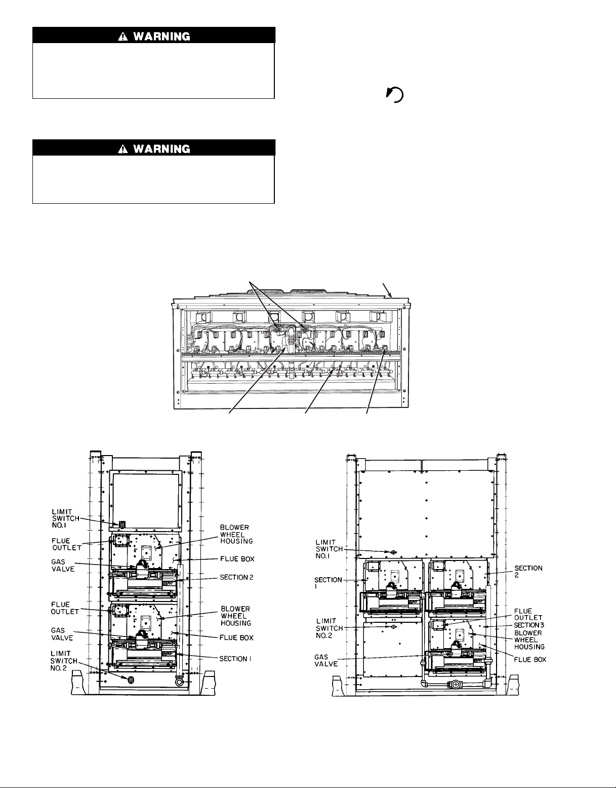
See Fig. 1 for location of gas valves. Refer to Fig. 2 while
proceeding with the following steps.
Step 1 — Set room thermostat to the lowest temperature
setting and set SYSTEM switch to HEAT.
Step 2 — Close the external manual gas valve.
Step 3 — Turn off the electrical supply to the unit.
Step 4 — Remove the burner compartment access panel.
Step 5 — Turn the control dial on the internal gas valve
clockwise to the OFF position and wait 5 minutes.
Step 6 — Turn control dial on internal gas valve clock-
wise to ON position.
Step 7 — Replace the burner compartment access panel.
Before performing recommended maintenance, be sure
main power switch to unit is turned off. Electrical shock
could cause personal injury.
Your combination heating/cooling unit is equipped with
an automatic intermittent pilot and induced draft power combustion blower.
Pilot will light automatically. Do not attempt to light by
hand; personal injury may result.
Manufacturer reserves the right to discontinue, or change at any time, specifications or designs without notice and without incurring obligations.
Book 1 1
Tab 1a 1c
PC 111 Catalog No. 564-920 Printed in U.S.A. Form 48-13SO Pg 1 3-98 Replaces: 48-12SO
Step 9 — Open the external gas valve.
Step 10 — Set room thermostat selector slightly above
room temperature to start unit. The induced-draft combustion air fan will start. Pilot lights within 30 seconds. Main
gas valves will open and main burners should ignite within
2 minutes from the pilot light ignition. Indoor blowers will
start within a few minutes of main ignition. On 48MA units,
if burners do not light within 2 minutes, the ignition control
will lock out. Begin again at Step 1. If burners still do not
light, contact your dealer for service.
Step 11 — Set the temperature selector on room thermo-
stat to desired setting.
Step 8 — Turn on the electrical supply to unit.
Step 2 — Close the external manual gas valve.
If the pilot fails to light, the main burners fail to light,
or the blower fails to come on, shut down gas heating
section and call your dealer for service. Failure to
follow these requirements could result in serious
personal injury.
TO SHUT UNIT OFF
Do not turn off the electrical power to unit without first
turning off the gas supply.
Failure to follow these procedures can result in
serious fire or personal injury.
See Fig. 1 for location of gas valve. Refer to Fig. 3 while
proceeding with the following steps.
Step 1 — Set room thermostat to lowest temperature set-
ting and set SYSTEM switch to OFF.
MAIN MANUAL GAS
SUPPLY VALVES
Step 3 — Turn off the electrical power supply to the unit.
Step 4 — Remove the burner compartment access panel.
Step 5 — Turn the control dial on the internal gas valve
counterclockwise to the OFF position.
Step 6 — Replace the burner compartment access panel.
Step 7 — If unit is being shut down because of a mal-
function, call your dealer as soon as possible.
If unit is being shut down because the heating season has
ended, restore electrical power to the unit to ensure operation of the cooling system during the cooling season.
Should overheating occur, or the gas supply fail to shut
off,shut off the manual gas valve to the furnace before shutting off the electrical supply.
Do not use this furnace if any part has been under water.
Immediately call a qualified service technician to inspect the
furnace and to replace any part of the control system and
any gas control which has been under water.
HEAT EXCHANGER
SECTION
FAN MOTOR
NOTE: High heat consists of sections 1 and 2. Low heat consists of
section 1 only.
48DJ,DK,FJ,FK,JJ,JK034-048
PILOT BURNERSFORCED DRAFT
Fig. 1 — Heat Section Details
MAIN REDUNDANT
GAS VALVES (ZONES)
48MA
NOTE: High heat consists of sections 1-3. Low heat consists of sections 1 and 2 only.
48DJ,DK,FJ,FK,JJ,JK054-074
2
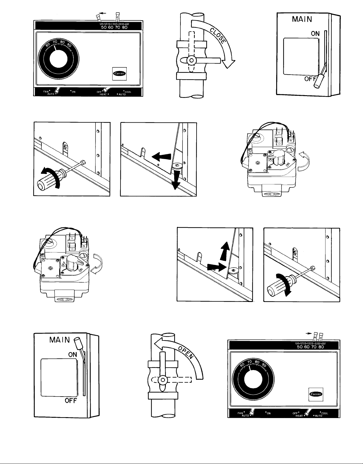
STEP 1
STEP 2
STEP 3
STEP 6
STEP 4
STEP 5
STEP 7
STEP 8
STEP 9
Fig.2—ToLight Unit
3
STEP 10
 Loading...