


PC880
COPYRIGHT
©
1999 CANON INC. CANON PC800s/900s REV.0 AUG. 1999 PRINTED IN JAPAN (IMPRIME AU JAPON)
REVISION 0
FY8-13GA-000
AUG. 1999
PC860
F13-8491 TYA00001-
PC880
F13-8291 TZA00001-
PC890
F13-8242 UAA00001-
PC920
F13-8431 TVB00001-
F13-8441 PUD00001-
PUE00001-
F13-8461 PUH00001-
PC921
F13-8432 TVC00001-
PC940
F13-8436 TVD00001-
PC941
F13-8437 TVE00001-
PC950
F13-8231 TVF00001-
F13-8241 PUF00001-
PUG00001-
PC960
F13-8434 TVG00001-
PC980
F13-8232 TVH00001-
PC981
F13-8233 TVJ00001-

COPYRIGHT
©
1999 CANON INC. CANON PC800s/900s REV.0 AUG. 1999 PRINTED IN JAPAN (IMPRIME AU JAPON)
IMPORTANT
THIS DOCUMENTATION IS PUBLISHED BY CANON INC., JAPAN, TO SERVE AS A SOURCE
OF REFERENCE FOR WORK IN THE FIELD.
SPECIFICATIONS AND OTHER INFORMATION CONTAINED HEREIN MAY VARY SLIGHTLY
FROM ACTUAL MACHINE VALUES OR THOSE FOUND IN ADVERTISING AND OTHER
PRINTED MATTER.
ANY QUESTIONS REGARDING INFORMA TION CONTAINED HEREIN SHOULD BE DIRECTED
TO THE COPIER SERVICE DEPARTMENT OF THE SALES COMPANY.
THIS DOCUMENT ATION IS INTENDED FOR ALL SALES AREAS, AND MA Y CONTAIN INFOR-
MATION NO T APPLICABLE TO CERTAIN AREAS.
COPYRIGHT © 1999 CANON INC.
Printed in Japan
Imprimé au Japon
Use of this manual should be strictly su-
pervised to avoid disclosure of confidential
information.
Prepared by
OFFICE IMAGING PRODUCTS TECHNICAL SUPPORT DIVISION
CANON INC.
5-1, Hakusan 7-chome, Toride-shi, Ibaraki 302-8501 Japan

COPYRIGHT © 1999 CANON INC. CANON PC800s/900s REV.0 AUG. 1999 PRINTED IN JAPAN (IMPRIME AU JAPON)
i
This service manual has been prepared for the PC800/900 Series machines,
providing basic information used for servicing the machines in the field so as to ensure
their quality and performance.
This service manual consists of the following chapters:
Chapter 1
General Description
introduces the machine's features, specifications,
names of parts, and how originals are reproduced.
Chapter 2
Basic Operation
explains how copies are made on a step-by-step basis.
Chapter 3
Exposure System
discusses the principles of operation used for the
machine's exposure system. It also explains the timing at which exposure-
related mechanisms are operated, and shows how they may be
disassembled/assembled and adjusted.
Chapter 4
Image Formation System
discusses the principles of operation used for the
machine's image formation system. It also explains the timing at which image
formation-related mechanisms are operated, and shows how they may be
disassembled/assembled and adjusted.
Chapter 5
Pick-Up/Feeding System
discusses the principles of operation used for the
machine's pickup/feeding system. It also explains the timing at which pickup/
feeding-related mechanisms are operated, and shows how they may be
disassembled/assembled and adjusted.
Chapter 6
Fixing System
discusses the principles of operation used for the machine's
fixing system. It also explains the timing at which fixing-related mechanisms
are operated, and shows how they may be disassembled/assembled and
adjusted.
Chapter 7
Externals/Auxiliary Mechanisms
discusses the principles of operation used
for the machine's externals/auxiliary mechanisms. It also explains the timing
at which auxiliary mechanism-related mechanisms are operated, and shows
how they may be disassembled/assembled and adjusted.
Chapter 8
ADF
explains the principles of operation of the ADF in view of electrical and
mechanical functions and in relation to their timing of operation. It also shows
how the unit may be disassembled/assembled and adjusted.
Chapter 9
Installation
introduces requirements for the site of installation, and shows
how the machine may be installed using step-by-step instructions.
Chapter 10
Maintenance and Servicing
provides tables of periodically replaced parts and
consumables/durables and scheduled servicing charts.
Chapter 11
Troubleshooting
provides tables of maintenance/inspection, standards/
adjustments, and problem identification (image fault/malfunction).
Appendix contains a general timing chart and general circuit diagrams.
INTRODUCTION

COPYRIGHT © 1999 CANON INC. CANON PC800s/900s REV.0 AUG. 1999 PRINTED IN JAPAN (IMPRIME AU JAPON)
ii
The following rules apply throughout this Service Manual:
1. Each chapter contains sections explaining the purpose of specific functions and the
relationship between electrical and mechanical systems with reference to the timing
of operation.
In the diagrams,
represents the path of mechanical drive—where a signal name
accompanies the symbol
, the arrow indicates the direction of the electric sig-
nal.
The expression “turn on the power” means flipping on the power switch, closing the
front door, and closing the delivery unit door, which results in supplying the machine
with power.
2. In the digital circuits, ‘1’ is used to indicate that the voltage level of a given signal is
“High,” while ‘0’ is used to indicate “Low.” (The voltage value, however, differs from
circuit to circuit.)
In practically all cases, the internal mechanisms of a microprocessor cannot be checked
in the field. Therefore, the operations of the microprocessors used in the machines
are not discussed: they are explained in terms of from sensors to the input of the DC
controller PCB and from the output of the DC controller PCB to the loads.
The descriptions in this Service Manual are subject to change without notice for
product improvement or other reasons, and major changes will be communicated in the
form of Service Information bulletins.
All service persons are expected to have a good understanding of the contents of this
Service Manual and all relevant Service Information bulletins and be able to identify and
isolate faults in the machine.

COPYRIGHT © 1999 CANON INC. CANON PC800s/900s REV.0 AUG. 1999 PRINTED IN JAPAN (IMPRIME AU JAPON)
iii
Model
PC860
PC880
PC890
PC920
PC920
PC920
PC920
PC921
PC940
PC941
PC950
PC950
PC950
PC960
PC980
PC981
Type
code
TYA
TZA
UAA
PUD
PUE
PUH
TVB
TVC
TVD
TVE
PUF
PUG
TVF
TVG
TVH
TVJ
Multi-
feeder
√
√
√
√
√
√
√
√
Single
feeder
√
√
√
√
√
√
√
√
Zoom
√
√
√
√
√
√
√
√
√
√
√
√
√
Default
ratio
2R2E
2R2E
2R2E
2R2E
2R2E
2R2E
3R1E
3R1E
3R1E
3R1E
2R2E
2R2E
3R1E
3R1E
3R1E
3R1E
ADF
as
standard
√
√
√
√
Cassette
250 sheets
250 sheets
250 sheets
Universal
Universal
Universal
Universal
Universal
Universal
Universal
Universal
Universal
500 sheets
Universal
500 sheets
500 sheets
Copying
speed
(cpm) at
Direct
12
12
12
10
10
10
10
10
13
13
12
12
13
10
13
13
The notation “√” indicates that the item in question is available.
• This service manual covers the models shown in the following table. Be sure to have a
good understanding of the difference from model to model before referring to this
manual.
Density
correction
switch
(SW101)
√
√
√
√
√
√
√
√

COPYRIGHT © 1999 CANON INC. CANON PC800s/900s REV.0 AUG. 1999 PRINTED IN JAPAN (IMPRIME AU JAPON)
iv

COPYRIGHT © 1999 CANON INC. CANON PC800s/900s REV.0 AUG. 1999 PRINTED IN JAPAN (IMPRIME AU JAPON)
v
CONTENTS
CHAPTER 1 GENERAL DESCRIPTION
CHAPTER 2 BASIC OPERATION
CHAPTER 3 EXPOSURE SYSTEM
I. FEATURES ..................................1-1
II. SPECIFICATIONS .......................1-2
A. Copier....................................1-2
B. ADF .......................................1-8
III. NAMES OF PARTS................... 1-10
A . External View ..................... 1-10
B. Cross Section..................... 1-13
IV. USING THE MACHINE ............. 1-15
A. Control Panel...................... 1-15
V. ROUTINE MAINTENANCE
BY THE USER .......................... 1-17
VI. IMAGE FORMATION ................ 1-20
A. Outline................................ 1-20
I. BASIC OPERATIONS .................. 2-1
A. Functional Construction ........2-1
B. Outline of Electrical
Circuitry .................................2-2
C. Basic Sequence of
Operations.............................2-3
D. Controlling the Main Motor
(M1) .......................................2-5
E. Inputs to and Outputs from
the DC Controller ..................2-7
I. OPERATIONS ..............................3-1
A. Outline...................................3-1
B. Varying the Reproduction
Ratio......................................3-2
C. Lens Drive System ................3-3
D. Scanner Drive System ..........3-4
II. EXPOSURE SYSTEM .................3-9
A. Controlling the Scanning
Lamp .....................................3-9
III. DISASSEMBLY/ASSEMBLY ..... 3-12
A. Scanner Drive Assembly.... 3-13
B. Lens Drive Assembly ......... 3-31
C. Exposure System ............... 3-37

COPYRIGHT © 1999 CANON INC. CANON PC800s/900s REV.0 AUG. 1999 PRINTED IN JAPAN (IMPRIME AU JAPON)
vi
CHAPTER 4 IMAGE FORMATION SYSTEM
CHAPTER 5 PICK-UP/FEEDING SYSTEM
I. IMAGE FORMATION SYSTEM ...4-1
A. Outline...................................4-1
B. Timing Chart for the Image
Formation System .................4-3
C. Controlling the Pr imary
Charging Roller Bias .............4-4
D. Controlling the Transfer
Roller Bias.............................4-8
E. Controlling the Developing/
Separation Static Eliminator
Bias .................................... 4-11
F. Measuring the Density of
Originals ............................. 4-16
G. Controlling the Side Blanking
Mechanism......................... 4-21
II. DISASSEMBLY/ASSEMBLY ..... 4-22
A. Cartridge ............................ 4-23
B. Transfer Charging
Assembly............................ 4-25
C. Blank Exposure .................. 4-26
I. PICKUP/FEEDING SYSTEM ....... 5-1
A. Outline................................... 5-1
B. Controlling the Pickup
Roller .....................................5-3
C. Controlling the Movement of
Paper.....................................5-9
D. Detecting Jams .................. 5-12
II. DISASSEMBLY/ASSEMBLY ..... 5-18
A. Pickup Assembly ................ 5-19
B. Multifeeder Assembly......... 5-28
C. Single-feeder Assembly ..... 5-31
D. Feeding Assembly.............. 5-33
E. Registration Roller
Assembly............................ 5-34
F. Delivery Assembly.............. 5-36
CHAPTER 6 FIXING SYSTEM
I. OPERATIONS ..............................6-1
A. Outline...................................6-1
B. Controlling the Fixing
Temperature ..........................6-3
II. DISASSEMBLY/ASSEMBLY ..... 6-10
A. Fixing Assembly................. 6-11

COPYRIGHT © 1999 CANON INC. CANON PC800s/900s REV.0 AUG. 1999 PRINTED IN JAPAN (IMPRIME AU JAPON)
vii
CHAPTER 7 EXTERNALS/AUXILIARY MECHANISMS
CHAPTER 9 INSTALLATION
CHAPTER 10 MAINTENANCE AND SERVICING
CHAPTER 8 ADF
I. FANS............................................7-1
II. POWER SUPPLY SYSTEM.........7-3
A. Outline of the Power Supply
System ..................................7-3
B. Power Supply Circuit.............7-4
C. Detecting an Error on
the Composite Power Supply
PCB .......................................7-6
D. Protecting the Power Supply
Circuit ....................................7-6
III. DISASSEMBLY/ASSEMBLY ........7-7
A. External Covers..................... 7-8
B. Control Panel...................... 7-15
C. Copyboard Glass ............... 7-16
D. Main Motor/Main Drive
Assembly............................ 7-17
E. Electrical System ............... 7-21
I. ADF ..............................................8-1
A. Outline................................... 8-1
B Basic Construction ................8-2
C. Basic Operations...................8-4
D. Detecting an Original ............8-6
E. Pickup Operation ...................8-8
F. Delivery .............................. 8-12
G. Controlling the Pickup
Motor .................................. 8-14
H. Controlling the Belt Motor .. 8-15
I. Detecting Original Jams..... 8-16
J. Power Supply ..................... 8-17
II. DISASSEMBLY/ASSEMBLY ..... 8-18
A. Removing the ADF............. 8-19
B. External Covers.................. 8-21
C. Drive System...................... 8-23
D. Feeding System ................. 8-26
E. Electrical System ............... 8-33
I. SELECTING A SITE ....................9-1
II. UNPACKING AND
INSTALLATION ............................9-2
A. Unpacking and Installation....9-2
B. Placing Copy Paper............... 9-9
III. MOVING THE MACHINE.......... 9-12
I. PERIODICALLY REPLACED
PARTS....................................... 10-1
II. DURABLES AND
CONSUMABLES ...................... 10-1
III. SCHEDULED SERVICING....... 10-1
IV. STORING AND HANDLING
THE CARTRIDGE..................... 10-2
A. Storing the Cartr idge with the
Packaging Seal Intact ........ 10-2
B. Storing and Handling the
Cartr idge with the Packaging
Seal Removed.................... 10-3

COPYRIGHT © 1999 CANON INC. CANON PC800s/900s REV.0 AUG. 1999 PRINTED IN JAPAN (IMPRIME AU JAPON)
viii
APPENDIX
CHAPTER 11 TROUBLESHOOTING
I. MAINTENANCE AND
INSPECTION ............................ 11-3
A. Image Adjustment Basic
Procedure........................... 11-3
B. Points to Note for
Servicing ............................ 11-4
II. STANDARDS AND
ADJUSTMENTS ....................... 11-5
A. Mechanical ......................... 11-5
B. ADF .................................. 11-30
C. Electr ical........................... 11-41
III. TROUBLESHOOTING IMAGE
FAULTS ................................... 11-48
A. Making Initial Checks ....... 11-48
B. Sample Image Faults ....... 11-52
C. Troubleshooting Image
Faults................................ 11-53
IV. TROUBLESHOOTING
MALFUNCTIONS.................... 11-61
A. Troubleshooting
Malfunctions ..................... 11-61
V. TROUBLESHOOTING FEEDING
PROBLEMS ............................ 11-75
A. Copy Paper Jam............... 11-75
B. Faulty Feeding.................. 11-78
VI. ARRANGEMENT AND
FUNCTIONS OF ELECTRICAL
PARTS..................................... 11-79
A. Sensors and Solenoids.... 11-79
B. Switches........................... 11-80
C. Lamp, Heater, Motor, Etc. 11-81
D. PCBs ................................ 11-82
E. ADF .................................. 11-83
F. Variable Resistors (VR) and
Check Pins by PCB.......... 11-84
VII. SELF DIAGNOSIS .................. 11-86
A. GENERAL TIMING CHART ........ A-1
B. SIGNALS AND
ABBREVIATIONS ....................... A-3
C. GENERAL CIRCUIT
DIAGRAM ................................... A-5
D. DC CONTROLLER CIRCUIT
DIAGRAM ................................... A-7
E. ADF CONTROLLER CIRCUIT
DIAGRAM ................................. A-15
F. COMPOSITE POWER SUPPLY
CIRCUIT DIAGRAM.................. A-19
G. CONTROL PANEL CIRCUIT
DIAGRAM ................................. A-27
H. AE SENSOR CIRCUIT
DIAGRAM ................................. A-29
I. SENSOR CIRCUIT
DIAGRAM ................................. A-30
J. NOISE FILTER CIRCUIT
DIAGRAM ................................. A-31
K. HIGH VOL TAGE CONT A CT
CIRCUIT DIAGRAM.................. A-32
L. BLANK EXPOSURE (front)
CIRCUIT DIAGRAM.................. A-33
M. BLANK EXPOSURE (rear)
CIRCUIT DIAGRAM.................. A-34
N. SPECIAL TOOLS...................... A-35
O. SOLVENTS/OILS...................... A-36

COPYRIGHT © 1999 CANON INC. CANON PC800s/900s REV.0 AU G. 1999 PRINTED IN JAPAN (IMPRIME AU JAPON)
CHAPTER 1
GENERAL DESCRIPTION
This chapter provides specifications of the machine, instructions on how to operate
the machine, and an outline of copying process.
I. FEATURES ..................................1-1
II. SPECIFICATIONS .......................1-2
A. Copier....................................1-2
B. ADF .......................................1-8
III. NAMES OF PARTS................... 1-10
A . External View ..................... 1-10
B. Cross Section..................... 1-13
IV. USING THE MACHINE ............. 1-15
A. Control Panel...................... 1-15
V. ROUTINE MAINTENANCE
BY THE USER .......................... 1-17
VI. IMAGE FORMATION ................ 1-20
A. Outline ................................ 1-20


CHAPTER 1 GENERAL DESCRIPTION
COPYRIGHT © 1999 CANON INC. CANON PC800s/900s REV.0 AUG. 1999 PRINTED IN JAPAN (IMPRIME AU JAPON)
1-1
I. FEATURES
1. Personal Copier with a Zoom Function and a Fixed Copyboard
• You can choose either a default enlargement/reduction ratio or any ratio between 70% and
141% in 1% increments.
2. Ecology-Conscious
• The use of a roller charging method has resulted in a considerable reduction of ozone: 0.01
ppm or less on the average, 0.02 ppm or less at maximum (1/100 to 1/1000 compared with
existing Canon machines).
3. SURF Fixing Assembly
• The wait time is 0 sec (at 20°C room temperature), enabling speedy copying work immedi-
ately after power-on.
4. Various Paper Sizes
• The paper may be between A4 (LGL) and A5 (STMT) (*Using the universal cassette).
• In manual feed mode, paper may be as large as A4 (LGL) or as small as a business card.
5. All-in-One Cartridge for Simple Maintenance
• The photosensitive drum, toner case, charging roller, developing assembly, and cleaning as-
sembly are constructed as a single entity (cartridge).
The user may expect quality copy images at all times as long as he/she performs simple
replacement/cleaning work.
6. Large Paper Source
• The source of paper may contain as many as 550 sheets of paper (500-sheet cassette +
multifeeder; multifeeder type).
7. Separate top unit
• The machine’s top unit may be opened to make jam removal easy.
8. ADF Type
• Continuous copying is possible with the use of the ADF.

CHAPTER 1 GENERAL DESCRIPTION
COPYRIGHT © 1999 CANON INC. CANON PC800s/900s REV.0 AUG. 1999 PRINTED IN JAPAN (IMPRIME AU JAPON)
1-2
II. SPECIFICATIONS
A. Copier
1. Type
Descriptions
Desk top
Fixed
Halogen lamp (80 V/110 W for 120V-model; 150 V/160 W
for 220/240 V-model)
Fixed focal point lens
OPC drum (24-mm dia.)
Item
Body
Copyboard
Source of light
Lens
Photosensitive medium
Table 1-201
2. Mechanisms
Descriptions
Indirect static reproduction
Roller (direct charging)
Slit (moving light source)
Auto or manual
Dry (toner projection)
Cassette (1 pc.)
Single-feeder (single-feeder type)
Multifeeder (multifeeder type)
Curvature separation + static eliminator
Flat heater
Blade
Center reference (copyboard)
Item
Reproduction
Charging
Exposure
Copy density adjustment
Development
Pickup
Separation
Fixing
Cleaning
Original orientation
Table 1-202

CHAPTER 1 GENERAL DESCRIPTION
COPYRIGHT © 1999 CANON INC. CANON PC800s/900s REV.0 AUG. 1999 PRINTED IN JAPAN (IMPRIME AU JAPON)
1-3
3. Performance
Descriptions
Sheet, book, 3-D object (2kg max.)
A4 (297 × 210 mm)/LGL (216 × 356 mm)
Inch/AB-configuration: 2R2E Inch-configuration: 3R1E
70% to 141% (in 1% increments
*1
)
0 sec (at 20°C room temperature)
10 sec or less (at 20°C room temperature; Direct, non-AE,
from the cassette)
100 (max.)
A4/LGL (297 × 210 mm/216 × 356 mm max.)
Business card (90 × 55 mm, min.)
Cassette:
Plain paper (64 to 80 g/m
2
), tracing paper (SM-1, A4R/
B5R), colored paper, recycled paper (64 to 80 g/m
2
; A4R/
B5R), eco paper (80 g/m
2
; A4R)
Manual Feeder:
Plain paper (52 to 128 g/m
2
), tracing paper (SM-1, GNT-
80
*2
; A4R/B5R), transparency
*2,*4
(A4R/LTRR
*3
), colored
paper, business card (200 g/m
2
or less), label sheet
*2
(A4R/
LTRR), recycled paper (64 to 80 g/m
2
; A4R/B5R), eco pa-
per (80 g/m
2
; A4R), postcard
*3
Double-Sided/Overlay Copying
*5
:
Plain paper (64 to 128 g/m
2
), colored paper, business card
(200 g/m
2
or less), recycled paper (64 to 80 g/m
2
; A4R/
B5R), eco paper (80 g/m
2
; A4R), postcard
*3
With claws
Universal cassette (250 sheets of 80 g/m
2
paper; A4/LGL to
A5/STMT)
250-sheet cassette (250 sheets of 80 g/m
2
)
500-sheet cassette (500 sheets of 80 g/m
2
)
5 mm deep (approx.; 50 sheets of 80 g/m
2
)
100 sheets (A4; 80 g/m
2
)
Leading edge: 2.0 ±1.5 mm (Direct; 4.0 mm or less otherwise)
Left/right: 0.0 +2.0, -0.0 mm (0 +4.0, -0.0 mm for LTR)
Provided (5 min, approx.; fixed)
*6
Item
Original type
Maximum original size
Reproduction ratio
Zoom
Wait time
First copy time
Continuous copying
Copy size
Copy paper type
Cassette
Multifeeder tray
Copy tray
Non-image width
Auto power-off
Table 1-203

CHAPTER 1 GENERAL DESCRIPTION
COPYRIGHT © 1999 CANON INC. CANON PC800s/900s REV.0 AUG. 1999 PRINTED IN JAPAN (IMPRIME AU JAPON)
1-4
*1. Applies only to models with a zoom function.
*2. Applies only to single pickup if the multifeeder is used.
*3. Applies only to vertical feeding.
*4. Upon delivery, be sure to remove each from the copy tray.
*5. Be sure to remove any curling before feeding for a second time.
*6. If stopped because paper ran out during copying operation, 1 hr.

CHAPTER 1 GENERAL DESCRIPTION
COPYRIGHT © 1999 CANON INC. CANON PC800s/900s REV.0 AUG. 1999 PRINTED IN JAPAN (IMPRIME AU JAPON)
1-5
4. Others
Descriptions
7.5°C to 32.5°C/44.5°F to 90.5°F
5% to 85% RH
607.95 to 1013.25 hPa (0.6 to 1 atm)
120 V 60 Hz 220/240 V 50 Hz, 60 Hz
TVBxxxxx PUDxxxxx PUHxxxxx
TVCxxxxx PUExxxxx
TVDxxxxx PUFxxxxx
TVExxxxx PUGxxxxx
TVFxxxxx TYAxxxxx
TVGxxxxx TZAxxxxx
TVHxxxxx UAAxxxxx
TVJxxxxx
0.9 kW or less
Standby: 1.2W (approx.; about 5min; reference only)
Copying: 0.4kWh (approx.; reference only)
Standby: -(sound power level by ISO)
Copying: (sound power level by ISO)
• Single-feeder type: 68 dB or less
• Multifeeder type: 66 dB or less
0.01 ppm or less (average; 0.02 ppm or less, max.)
Copyboard Type
484.9 × 448.2 × 297.5 mm
*1
/ 329.0 mm
*2
19.1 in. × 17.6 in × 11.7 in
*1
/ 13.0 in
*2
ADF Type
484.9 × 448.2 × 358.3 mm
*1
/ 389.8 mm
*2
19.1 in × 17.6 in × 14.1 in
*1
/ 15.3 in
*2
Copyboard Type
Single-feeder type: 19.3 kg
*1
/ 42.5 lb
*1
, 20.9 kg
*2
/ 46.0 lb
*2
Multifeeder type: 19.5 kg
*1
/ 42.9 lb
*1
, 21.1 kg
*2
/ 46.4 lb
*2
ADF Type
Single-feeder type: 23.8 kg
*1
/ 52.4 lb
*1
, 25.2 kg
*2
/ 55.4 lb
*2
Multifeeder type: 24.0 kg
*1
/ 52.8 lb
*1
, 25.4 kg
*2
/ 55.9 lb
*2
Copy paper: Keep wrapped, and protect against humidity.
Toner: Avoid direct sunlight, and store at 40°C/104°F, 85%
or less.
Item
Operating condition
Temperature
Humidity
Atmospheric pressure
Power source
Serial number
Maximum power consumption
Noise
Ozone
Dimensions (WxDxH)
Weight (including the cassette)
Consumables
Table 1-204
*1. 250-sheet cassette type
*2. 500-sheet cassette type

CHAPTER 1 GENERAL DESCRIPTION
COPYRIGHT © 1999 CANON INC. CANON PC800s/900s REV.0 AUG. 1999 PRINTED IN JAPAN (IMPRIME AU JAPON)
1-6
5. Default Ratios
Table 1-205
2R2E (Inch/AB-configuration)
1:1.000
1:0.707
1:0816
1:1.154
1:1.414
Item
Direct
Reduce I
Reduce II
Reduce III
Reduce IV
Enlarge I
Enlarge II
3R1E (Inch-configuration)
1:1.000
1:0.707
1:0.786
1:0.860
1:1.414

CHAPTER 1 GENERAL DESCRIPTION
COPYRIGHT © 1999 CANON INC. CANON PC800s/900s REV.0 AUG. 1999 PRINTED IN JAPAN (IMPRIME AU JAPON)
1-7
6. Copying Speed
Table 1-206
*1. The number of copies starting with the pickup operation that follows the delivery of the
19th copy in a continuous copying job. (See p.5-8)
The specifications are subject to change for product improvement.
Number of copies
( Multifeeder
*1
)
(Copies / min)
13 (9)
11 (8)
13 (9)
13 (9)
13 (9)
13 (9)
10 (9)
12 (9)
12 (9)
12 (9)
12 (9)
12 (9)
12 (9)
10 (9)
10 (9)
10 (9)
10 (9)
10 (9)
10 (9)
10 (9)
10 m(9)
10 (9)
9
10 (9)
10 (9)
10 (9)
10 (9)
9
Copy size
LTRR
LGL
STMTR
MIN
LGL → LTRR
MARJIN
MAX
A4R
B5R
A5R
A4R → A5R
B5R → A5R
B5R → A4R
A5R→ A4R
A4R
B5R
A5R
A4R → A5R
B5R → A5R
B5R → A4R
A5R → A4R
LTRR
LGL
STMTR
MIN
LGL → LTRR
MARJIN
MAX
Reproduction ratio
Direct
Reduce I (70.7%)
Reduce II (78.6%)
Reduce IV (86.0%)
Enlarge II (141.4%)
Direct
Reduce I (70.7%)
Reduce III (81.6%)
Enlarge I (115.4%)
Enlarge II (141.4%)
Direct
Reduce I (70.7%)
Reduce III (81.6%)
Enlarge I (115.4%)
Enlarge II (141.4%)
Direct
Reduce I (70.7%)
Reduce II (78.6%)
Reduce III (86.0%)
Enlarge II (141.4%)
Copying speed
at Direct
13
12
10
10

CHAPTER 1 GENERAL DESCRIPTION
COPYRIGHT © 1999 CANON INC. CANON PC800s/900s REV.0 AUG. 1999 PRINTED IN JAPAN (IMPRIME AU JAPON)
1-8
B. ADF
Table 1-207
Descriptions
Auto pickup/delivery
Face-down
Center reference
Top separation
Single-sided (50 to 128 g/m
2
)
A5 (STMT) to A4R (LTRR), LGL
Length: 139.7 to 355.6 mm (feeding direction)
Width: 139.7 to 215.9 mm
30 sheets (80 g/m
2
or less; about 3 mm in height)
Single-sided original to single-sided copy
Yes (in feeding direction)
No
Yes
446 mm/sec
IPC
Width: 474 mm/ 18.7 in.
(659 mm/ 25.9 in. with the tray open)
Depth: 394 mm/ 15.5 in.
Height: 74 mm/ 2.9 in. (216 mm/ 8.5 in. with the tray open)
5 kg/ 11 lb (approx.)
24 VDC and 5 VDC (from the host)
40 W or less
Temperature: same as the host
Humidity: same as the host
Item
Original pickup
Original orientation
Original position
Original separation
Original type
Stack
Original processing mode
Original size detection
Mixed original sizes
Original detection
Original feeding speed
Communication with host
Dimensions
Weight
Power source
Maximum power consumption
Operating environment

CHAPTER 1 GENERAL DESCRIPTION
COPYRIGHT © 1999 CANON INC. CANON PC800s/900s REV.0 AUG. 1999 PRINTED IN JAPAN (IMPRIME AU JAPON)
1-9
*1. The following may not be used as an original:
• Sheet with a staple, clip, or glue.
• Sheet with a cut, hole, or tear.
• Sheet with holes for binding.
• Sheet with a carbon back.
• Sheet with a cut-and-paste piece.
• Sheet with curling, bending, or wrinkling.
The specifications are subject to change for product improvement.
CHAPTER 1 GENERAL DESCRIPTION
COPYRIGHT © 1999 CANON INC. CANON PC800s/900s REV.0 AUG. 1999 PRINTED IN JAPAN (IMPRIME AU JAPON)
1-10
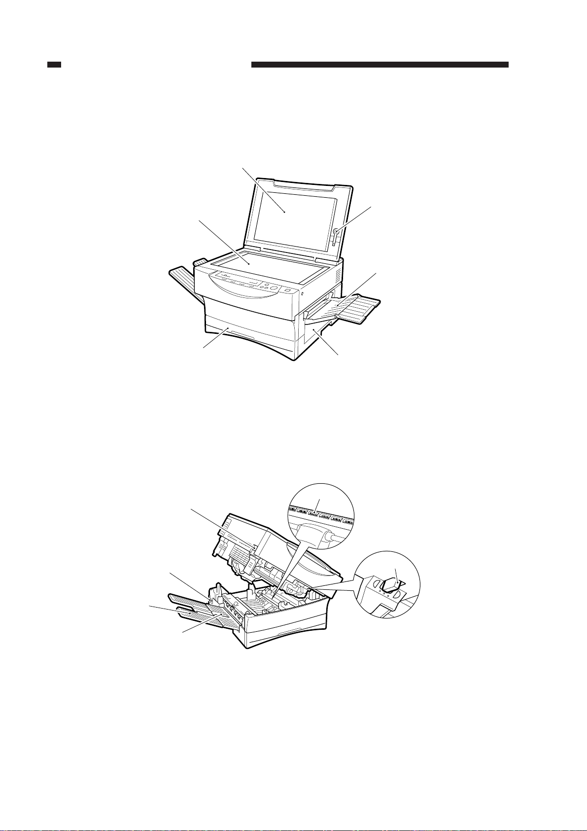
[1] Copy tray
[2] Power cord connector
[3] Open/close lever
[1] Copyboard cover
[2] Static eliminator cleaner
[3] Manual feed tray
[4] Right door
[5] Cassette
[6] Copyboard glass
[4] Static eliminator
[5] Copy density correction switch
[6] Delivery guide plate
[1]
[6]
[5]
[2]
[3]
[4]
[5]
[3]
[6]
[2]
[1]
[4]
III. NAMES OF PARTS
A. External View
1. Copyboard Type
Figure 1-301
Figure 1-302
CHAPTER 1 GENERAL DESCRIPTION
COPYRIGHT © 1999 CANON INC. CANON PC800s/900s REV.0 AUG. 1999 PRINTED IN JAPAN (IMPRIME AU JAPON)
1-11
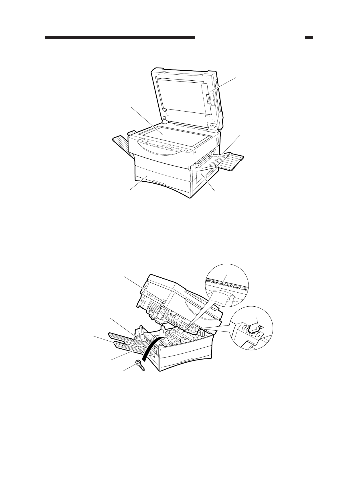
[1] ADF
[2] Manual feed tray
[3] Right door
[1] Static eliminator cleaner
[2] Delivery guide plate
[3] Copy tray
[4] Power cord connector
[4] Cassette
[5] Copyboard glass
[5]
[4]
[2]
[3]
[1]
[5] Open/close lever
[6] Static eliminator
[7] Copy density correction switch
[7]
[6]
[5]
[2]
[4]
[3]
[1]
2. ADF Type
Figure 1-303
Figure 1-304
CHAPTER 1 GENERAL DESCRIPTION
COPYRIGHT © 1999 CANON INC. CANON PC800s/900s REV.0 AUG. 1999 PRINTED IN JAPAN (IMPRIME AU JAPON)
1-12
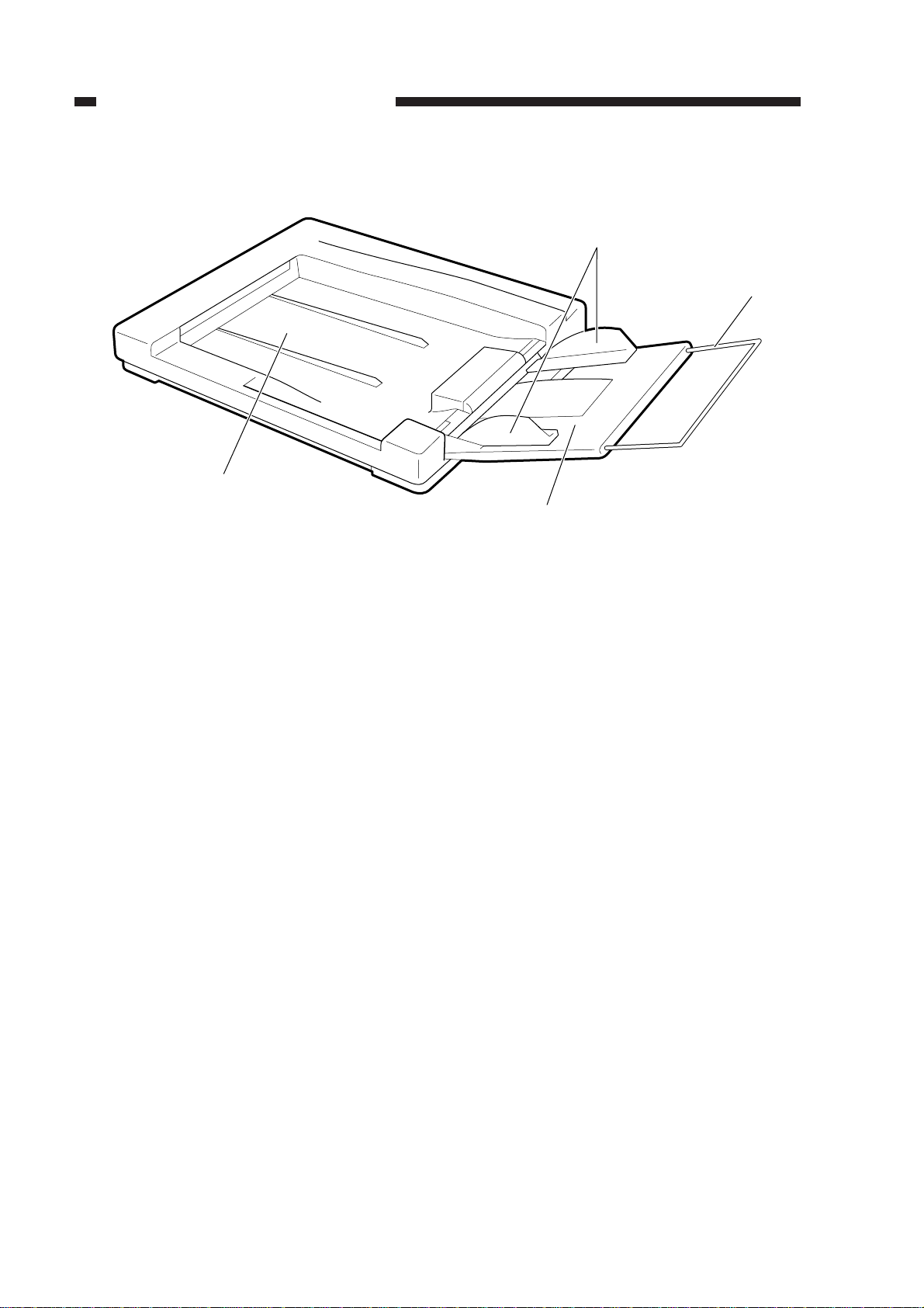
[1]
[4]
[3]
[2]
3. ADF
Figure 1-305
[1] Original tray
[2] Original delivery tray
[3] Slide guide
[4] Auxiliary tray
CHAPTER 1 GENERAL DESCRIPTION
COPYRIGHT © 1999 CANON INC. CANON PC800s/900s REV.0 AUG. 1999 PRINTED IN JAPAN (IMPRIME AU JAPON)
1-13
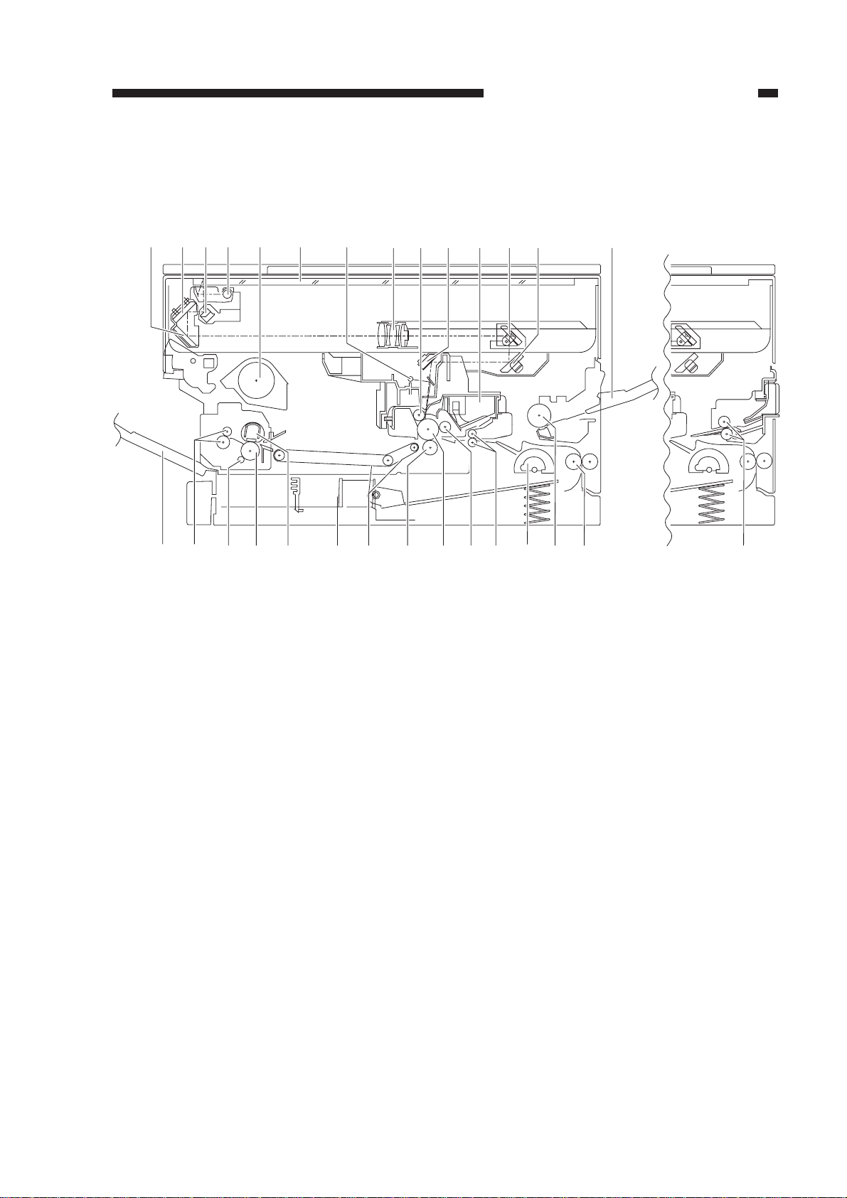
[1] No. 3 mirror
[2] No. 2 mirror
[3] No. 1 mirror
[4] Scanning lamp
[5] Heat exhaust fan
[6] Copyboard glass
[7] Side blanking lamp
[8] Lens
[9] Primary charging roller
[10] No. 6 mirror
[11] Cartridge
[12] No. 4 mirror
[13] No. 5 mirror
[14] Multifeeder tray
[15] Vertical path roller
[16] Multifeeder pickup roller
[17] Cassette pickup roller
[18] Registration roller
[19] Developing cylinder
[20] Photosensitive drum
[21] Transfer roller
[22] Feed belt
[23] Cassette
[24] Fixing upper unit
[25] Fixing lower roller
[26] Cleaning roller
[27] Delivery roller
[28] Copy tray
[29] Single-feeder pickup roller
[1]
[28] [27] [26] [25] [24] [23] [22] [21] [20] [19] [18] [17] [29][16] [15]
[2] [3] [4] [5] [6] [7] [8] [9] [10] [11] [12] [13] [14]
B. Cross Section
1. Body
Figure 1-306

CHAPTER 1 GENERAL DESCRIPTION
COPYRIGHT © 1999 CANON INC. CANON PC800s/900s REV.0 AUG. 1999 PRINTED IN JAPAN (IMPRIME AU JAPON)
1-14
[1] Delivery roller
[2] Copy tray
[3] Pickup roller 2
[4] Pickup roller 1
[5] Copyboard tray
[6] Auxiliary tray
[7] Guide plate
[8] Separation pad
[9] Registration roller
[10] Feed belt drive roller
[11] Feed belt
[12] Feed belt roller
[13] Feed belt link slave roller
[6][5][4][3][2][1]
[13] [12]
[11] [9] [8] [7][10]
2. ADF
Figure 1-307
CHAPTER 1 GENERAL DESCRIPTION
COPYRIGHT © 1999 CANON INC. CANON PC800s/900s REV.0 AUG. 1999 PRINTED IN JAPAN (IMPRIME AU JAPON)
1-15
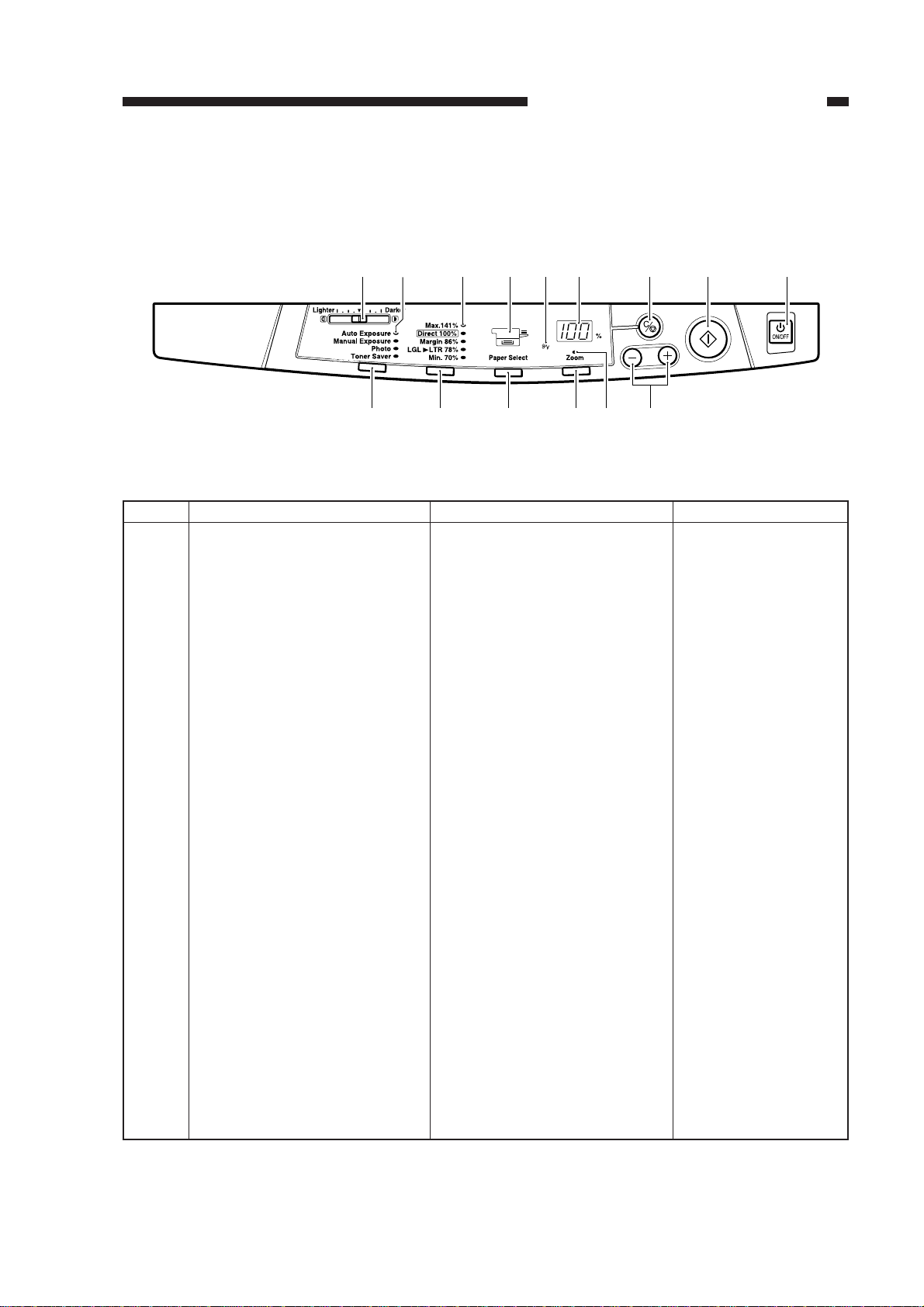
Description
Adjusts the density of copies
manually.
Indicates the selected copy den-
sity mode.
Indicates the selected default ra-
tio.
Indicates the selected cassette/
manual feed tray.If there is no
paper loaded, it flashes.
Flashes in response to a jam.
• Indicates the number of copies
or reproduction ratio.
• The symbol “%” turns on
when indicating a ratio.
Stops copying or returns copy-
ing mode to standard mode.
Starts copying.
Turns on and off the power.
No.
1
2
3
4
5
6
7
8
9
Remarks
100 (max.; continuous
copying)
Standard Mode
Ratio: 100%
Count: 1
Paper source: cassette
Copy density: auto
mode
Name
Copy density adjusting lever
Copy density mode indicator
Default ratio indicator
Paper selection indicator
*1
Jam indicator
Count/ratio indicator
Clear/stop key
Copy start key
Power switch
[8] [9][7][6][1]
[15] [14] [12] [10][11][13]
[5][4][3][2]
IV. USING THE MACHINE
A. Control Panel
Figure 1-401

CHAPTER 1 GENERAL DESCRIPTION
COPYRIGHT © 1999 CANON INC. CANON PC800s/900s REV.0 AUG. 1999 PRINTED IN JAPAN (IMPRIME AU JAPON)
1-16
Description
No.
Remarks
Name
10
11
12
13
14
15
Count/zoom set key
Zoom indicator
*2
Zoom key
*2
Paper selection key
*1
Default ratio key
Copy density mode selection
key
Sets the number of copies or a
zoom ratio.
Turns on when zoom mode is
selected.
Selects/deselects zoom mode.
Selects the cassette/ manual
feed tray.
Selects a default reproduction
ratio.
Selects copying density mode.
May be between 70%
and 141% in 1% incre-
ments.
Table 1-401
*1. Applies only to a multifeeder model.
*2. Applies only to a model equipped with a zoom function.

CHAPTER 1 GENERAL DESCRIPTION
COPYRIGHT © 1999 CANON INC. CANON PC800s/900s REV.0 AUG. 1999 PRINTED IN JAPAN (IMPRIME AU JAPON)
1-17
Zoom
V. ROUTINE MAINTENANCE BY THE USER
Instruct the user to clean the following if images tend to be soiled or copy paper tends to jam
often.
1. Soiled Images
a. Copyboard Glass/Copyboard Cover
Clean the cover with a moist cloth (with water or mild detergent solution); then, dry wipe it.
b. Feeding Belt (ADF type)
b.1 Cleaning in Feeder Cleaning Mode
1) Turn on the machine, and hold down the Copy Density Mode Selection key for 4 sec or
more.
• The count/ratio indicator will indicate ‘U6’.
Figure 1-501
2) Place about 10 sheets of blank copy paper (A4/LTR) on the original tray of the ADF.
3) Press the Copy Start key.
• Copy paper will be fed from the original tray.
• The indicator flashes ‘U6’ while the feeder is being cleaned.
4) Press the Copy Density Mode Selection key to end the mode.
Caution:
• You cannot start feeder cleaning mode while the machine is making copies or if an error
exists.
• The auto power-off mechanism does not operate while feeder cleaning mode is being
executed.
CHAPTER 1 GENERAL DESCRIPTION
COPYRIGHT © 1999 CANON INC. CANON PC800s/900s REV.0 AUG. 1999 PRINTED IN JAPAN (IMPRIME AU JAPON)
1-18
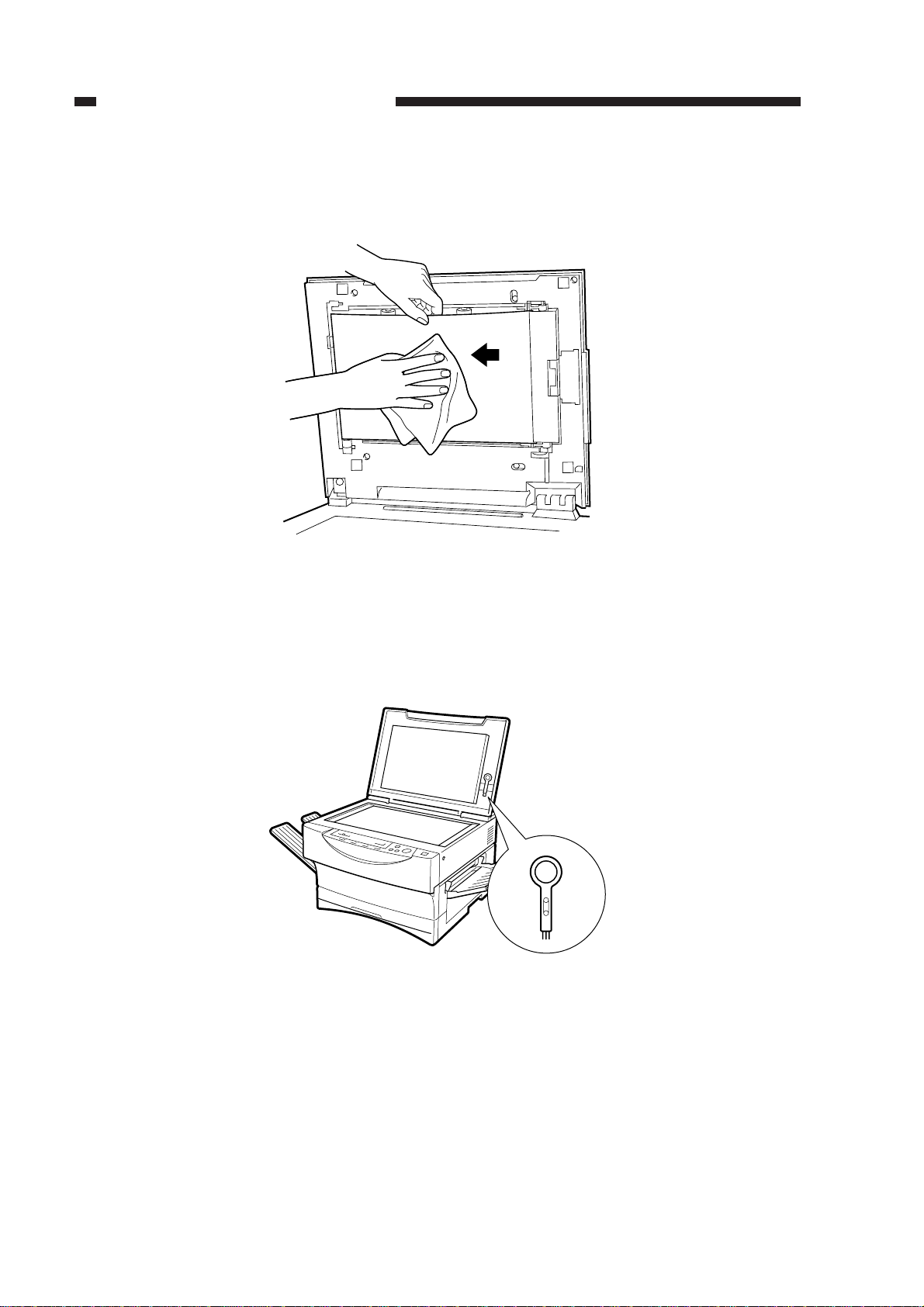
b.2 Cleaning by Hand
1) Wipe the feed belt with a moist cloth (water or mild detergent solution) in the direction of
the arrow in the figure; then, dry wipe it.
Figure 1-502
2. If Jams Occur Frequently
a. Static Eliminator
1) Remove the static eliminator cleaner from the machine.
Figure 1-503 (Copyboard type)
 Loading...