


 Loading...
REVISION 0
PC860
F13-8491 TYA00001-
PC880
F13-8291 TZA00001-
PC890
F13-8242 UAA00001-
PC920
F13-8431 TVB00001-
F13-8441 PUD00001PUE00001- F13-8461 PUH00001-
PC921
F13-8432 TVC00001-
PC940
F13-8436 TVD00001-
PC941
F13-8437 TVE00001-
PC950
F13-8231 TVF00001-
F13-8241 PUF00001PUG00001-
PC960
F13-8434 TVG00001-
PC980
F13-8232 TVH00001-
PC981
F13-8233 TVJ00001-
AUG. 1999 |
FY8-23B6-000 |
COPYRIGHT © 1999 CANON INC. |
CANON PC800s/900s REV.0 AUG. 1999 PRINTED IN JAPAN (IMPRIME AU JAPON) |

IMPORTANT
THIS DOCUMENTATION IS PUBLISHED BY CANON INC., JAPAN, TO SERVE AS A SOURCE OF REFERENCE FOR WORK IN THE FIELD.
SPECIFICATIONS AND OTHER INFORMATION CONTAINED HEREIN MAY VARY SLIGHTLY FROM ACTUAL MACHINE VALUES OR THOSE FOUND IN ADVERTISING AND OTHER PRINTED MATTER.
ANY QUESTIONS REGARDING INFORMATION CONTAINED HEREIN SHOULD BE DIRECTED TO THE COPIER SERVICE DEPARTMENT OF THE SALES COMPANY.
THIS DOCUMENTATION IS INTENDED FOR ALL SALES AREAS, AND MAY CONTAIN INFORMATION NOT APPLICABLE TO CERTAIN AREAS.
COPYRIGHT © 1999 CANON INC.
Printed in Japan
Imprimé au Japon
Use of this manual should be strictly su-
pervised to avoid disclosure of confidential
information.
Prepared by
OFFICE IMAGING PRODUCTS TECHNICAL SUPPORT DIVISION
CANON INC.
5-1, Hakusan 7-chome, Toride-shi, Ibaraki 302-8501 Japan
COPYRIGHT © 1999 CANON INC. |
CANON PC800s/900s REV.0 AUG. 1999 PRINTED IN JAPAN (IMPRIME AU JAPON) |
•This service handbook covers the models shown in the following table. Be sure to have a good understanding of the difference from model to model before referring to this handbook.
Model |
Type |
Multi- |
Single |
Zoom |
Default |
|
Density |
ADF |
Cassette |
Copying |
|
code |
feeder |
feeder |
|
ratio |
|
correction |
as |
|
speed |
|
|
|
|
|
|
|
switch |
standard |
|
(cpm) at |
|
|
|
|
|
|
|
(SW101) |
|
|
Direct |
PC860 |
TYA |
|
Ö |
Ö |
2R2E |
|
Ö |
|
250 sheets |
12 |
PC880 |
TZA |
Ö |
|
Ö |
2R2E |
|
Ö |
|
250 sheets |
12 |
PC890 |
UAA |
Ö |
|
Ö |
2R2E |
|
Ö |
Ö |
250 sheets |
12 |
PC920 |
PUD |
|
Ö |
Ö |
2R2E |
|
Ö |
|
Universal |
10 |
PC920 |
PUE |
|
Ö |
Ö |
2R2E |
|
Ö |
|
Universal |
10 |
PC920 |
PUH |
|
Ö |
Ö |
2R2E |
|
Ö |
|
Universal |
10 |
PC920 |
TVB |
|
Ö |
Ö |
3R1E |
|
|
|
Universal |
10 |
PC921 |
TVC |
|
Ö |
|
3R1E |
|
|
|
Universal |
10 |
PC940 |
TVD |
|
Ö |
Ö |
3R1E |
|
|
|
Universal |
13 |
PC941 |
TVE |
Ö |
Ö |
Ö |
3R1E |
|
Ö |
|
Universal |
13 |
PC950 |
PUF |
|
2R2E |
|
|
Universal |
12 |
|||
PC950 |
PUG |
Ö |
|
Ö |
2R2E |
|
Ö |
|
Universal |
12 |
PC950 |
TVF |
Ö |
|
Ö |
3R1E |
|
|
Ö |
500 sheets |
13 |
PC960 |
TVG |
Ö |
|
Ö |
3R1E |
|
|
Universal |
10 |
|
PC980 |
TVH |
Ö |
|
Ö |
3R1E |
|
|
Ö |
500 sheets |
13 |
PC981 |
TVJ |
Ö |
|
|
3R1E |
|
|
Ö |
500 sheets |
13 |
The notation “ Ö” indicates that the item in question is available.
i
i i

CONTENTS
CHAPTER 1 MAINTENANCE AND INSPECTION
A. |
Periodically Replaced Parts ......... |
1-1 |
B. |
Durables and Consumables ......... |
1-1 |
C. |
Scheduled Servicing .................... |
1-1 |
D. |
Storing and Handling |
|
|
the Cratridge ................................ |
1-2 |
D-1.Storing the Cartridge with |
|
|
|
the Packaging Seal Intact ............ |
1-2 |
D-2.Storing and Handling the Cartridge
|
with the Packaging Seal |
|
|
Removed ...................................... |
1-3 |
E. |
Image Adjustment Basic |
|
|
Procedure..................................... |
1-7 |
F. |
Points to Note for Servicing ......... |
1-8 |
1 |
2 |
3 |
CHAPTER 2 STANDARDS AND ADJUSTMENTS
A. |
Mechanical |
...................................2-1 |
C. Electrical ................................... |
2-37 |
B. |
ADF ........................................... |
2-26 |
|
|
4 |
CHAPTER 3 ARRANGEMENT AND FUNCTIONS OF
ELECTRICAL PARTS
A. |
Sensors and Solenoids ................ |
3-1 |
E. |
ADF .............................................. |
3-5 |
B. |
Switches ....................................... |
3-2 |
F. |
Variable Resistors (VR) and |
|
C. Lamp, Heater, Motor, Etc. ............ |
3-3 |
|
Check Pins by PCB ...................... |
3-6 |
|
D. |
PCBs ............................................ |
3-4 |
|
|
|
CHAPTER 4 SELF DIAGNOSIS
A. Self Diagnosis .............................. |
4-1 |
|
|
|
|
APPENDIX
A. |
General Timing Chart .................. |
A-1 |
D. |
Special Tools ............................... |
A-7 |
B. |
Signals and Abbreviations .......... |
A-3 |
E. |
Solvents/Oils ............................... |
A-8 |
C. |
General Circuit Diagram ............. |
A-5 |
F. |
Specifications .............................. |
A-9 |
iii

CHAPTER 1 MAINTENANCE AND INSPECTION
CHAPTER 1 MAINTENANCE AND INSPECTION
A.Periodically Replaced Parts
The machine does not have parts which must be replaced on a periodical basis.
B.Durables and Consumables
The machine does not have items designated as durables or consumables.
C.Scheduled Servicing
The machine does not have any parts which require scheduled servicing.
1 |
1-1

CHAPTER 1 MAINTENANCE AND INSPECTION
D.Storing and Handling the Cartridge
The cartridge is subject to the effects of the environment whether its packing seal is intact or removed or whether it is inside the machine or otherwise, changing over time regardless of the number of copies made. The degree of change is highly dependent on the site of installation and how it is maintained, and no general rule may be drawn; however, it is important to exercise care when storing or handling it.
D-1. Storing the Cartridge with the Packaging Seal Intact
If you are storing the cartridge in a warehouse or workshop, be sure that the environment is as indicated in Table 1-1; in addition, keep the following in mind:
•Avoid direct rays of the sun.
•Avoid vibration.
•Do not subject it to impact (as by hitting or dropping it).
Temperature |
Normal (9/10 of entire storage period) |
|
between 0°C/32°F and 35°C/95°F |
||||
|
|
|
|
|
|
|
|
|
|
High temperature |
|
between 35°C/95°F and 45°C/113°F |
|||
|
|
|
|
||||
|
Harsh (1/10 of entire storage period) |
|
|
|
|
||
|
Low temperature |
|
between -20°C/-4°F and 0°C/32°F |
||||
|
|
|
|
||||
|
|
|
|
|
|
|
|
|
Temperature changes (within 3-min period; approx.) |
|
from 40°C/104°F to 15°C/59°F |
||||
|
|
from -20°C/-4°F to 25°C/77°F |
|||||
|
|
|
|
|
|
||
|
|
|
|
|
|||
Humidity |
Normal (9/10 of entire storage period) |
|
between 35% and 85% RH |
||||
|
|
|
|
|
|
|
|
|
|
High humidity |
|
between 85% and 95% RH |
|||
|
|
|
|
||||
|
Harsh (1/10 of entire storage period) |
|
|
|
|
||
|
Low humidity |
|
between 10% and 35% RH |
||||
|
|
|
|
||||
|
|
|
|
|
|
|
|
|
|
Atmospheric pressure |
|
between 613.3 and 1013.3 |
|||
|
|
|
(hPa; 0.6 to 1 atm) |
||||
|
|
|
|
|
|
||
|
|
|
|
|
|||
|
|
Table 1-1 Temperature/Humidity Conditions for Storage |
|||||
|
|
|
|
|
|
|
|
|
|
Temperature |
|
|
Humidity |
|
|
|
|
between -20°C/-4°F and 40°C/104°F |
|
90% or less |
|
||
Table 1-2 Conditions for Transportation
1-2

CHAPTER 1 MAINTENANCE AND INSPECTION
D-2. Storing and Handling the Cartridge with the Packaging Seal Removed
The photosensitive medium is an organic photoconducting (OPC) material, which would deteriorate if subjected to storing light.
The cartridge also holds toner, requiring the user to exercise care when storing or handling it. (Be sure that the user stores it in an appropriate storage box for storage.)
1.Storage after Removing the Packaging Seal
a.Avoid areas subject to the direct rays of the sun, i.e., near a window. Do not keep it in a car for a long time, as it will be subjected to an extremely high temperature. (This applies even if the cartridge is inside a protective box.)
b.Avoid areas subjected to high or low temperature/humidity or where temperature or humidity tends to change abruptly (e.g., near an air conditioner).
c.Avoid areas subject to dust, ammonium gas, or organic solvent.
d.Make sure that the cartridge is stored at 40°C/104°F or lower.
1-3

CHAPTER 1 MAINTENANCE AND INSPECTION
2.Handling the Cartridge
a.Before setting the cartridge in the machine or if copies have white spots as when it starts to run out of toner, hold the cartridge level and shake it about 90° several times as shown in Figure 1- 1 to even out the toner inside.
If you shake it in a different way, the toner can spill out of the developing assembly or the cleaning assembly.
Figure 1-1 |
b. Do not place the cartridge on its end or turn it over as shown in Figure 1-2.
Figure 1-2
1-4
CHAPTER 1 MAINTENANCE AND INSPECTION
c.Do not touch the surface of the photosensitive drum as by opening the shutter for the photosensitive drum cover found at the bottom of the cartridge.
(If you have soiled the surface of the photosensitive drum, wipe it with a flannel cloth coated with toner. Do not clean it using solvents.)
d.Do not disassemble the cartridge.
e.Do not subject the cartridge to excess vibration or impact. In particular, do not impose force on the shutter for the photosensitive drum shutter.
f.Make sure that it is out of reach of children.
g.The photosensitive drum is susceptible to strong light, and the light-blocking shutter is provided as a means of protection.
If the drum is exposed to strong light for a long time, however, copies can start to show white spots or vertical bands. Try leaving the machine alone as long as possible if such a problem is noted; the memory (i.e., cause of white spots or vertical bands), however, may not disappear. Keep the following in mind:
Caution:
1.Try to work briskly when removing a jam or replacing the cartridge.
2.If the cartridge must be taken out of the machine for storage, be sure to put it in a protective box or put a cover over it. Do not leave it outside the machine unprotected.
Reference:
If the photosensitive drum is exposed to light of 1500 lux (general lighting) for 5 min and then left alone in a dark place for 5 min, it should recover so that it will not cause practical problems. Nevertheless, avoid direct sunshine. (The rays of the sun is as strong as 10000 and 30000 lux.)
1-5

Making Pre-Checks
Clean the parts.
Scanning system, pickup/feeding system, delivery assembly
NO
Is the copy density correction switch (SW101) set to the middle index?
(Note 1)
Set it at |
YES |
the middle. |
|
Select non-AE, and set the copy density adjusting lever to the middle index; then, make two to three copies of the Test Sheet (NA-3).
Check the following:
1.Density of gray scale No. 9
2.Presence/absence of difference between front and rear (Note 2)
3.Density of gray scale No. 1 (good or bad; Note 2)
4.Fogging of background (Note 2)
E.Image Adjustment Basic Procedure
Adjusting the Optimum Density
Is gray scale No. |
9 |
YES |
barely visible? |
|
|
NO
Can the
deviation be corrected
YES
using the copy density correction switch (SW101)?
(Note 1)
NO
Is the optimum
density obtained by intensity YES adjustment?
(Note 3)
NO
Check the following:
1.Cartridge
2.Scanning lamp
3.AE sensor PCB
4.DC controller PCB
5.Composite power supply PCB (See the appropriate troubleshooting
procedure.)
END
Note:
1.Applies only if the machine is equipped with a copy density correction switch (SW101).
2.The machine is not equipped with a function to correct image faults. See the appropriate troubleshooting procedure.
3.See p. 2-38.
1-7

F.Points to Note for Servicing
Copyboard, Scanner
Item |
Tools/solvent |
Work/remarks |
|
|
|
Copyboard cover |
Alcohol |
Cleaning. |
Copyboard glass |
Alcohol |
Cleaning. |
Lens |
Blower brush |
Cleaning. |
Scanning lamp |
Lint-free paper |
Dry wiping. |
Reflecting plate |
Blower brush |
If dirt cannot be removed, |
No. 1 through |
|
dry-wiping with lint-free |
No. 6 mirror |
|
paper. |
|
|
|
Fixing Assembly, Delivery Assembly
Item |
Tools/solvent |
Work/remarks |
|
|
|
Inlet guide |
Solvent |
Cleaning. |
|
|
|
ADF
Item |
Tool/solvent |
Work/remarks |
|
|
|
Feeding belt |
Cloth moistened with |
Dry-wiping. |
|
water* |
|
Separation pad |
Cloth |
Cleaning. |
Pickup roller |
Cloth moistened with |
Cleaning. |
|
water* or alcohol |
|
|
|
|
*Be sure to wring it well.
Cartridge
Item |
Tools/solvents |
Work/remarks |
|
|
|
Drum cover |
Most cloth |
Cleaning; be sure to |
shutter |
|
remove all toner to prevent |
|
|
toner soiling images. |
|
|
|
Pickup, Feeding, and Transfer Assemblies and Static Eliminator
Item |
Tools/solvents |
Work/remarks |
|
|
|
Single-feeder |
Moist cloth or alcohol |
Cleaning. |
pickup roller |
|
|
Multifeeder, |
Moist cloth or alcohol |
Cleaning. |
Pickup roller |
|
|
Cassette pickup |
Moist cloth or alcohol |
Cleaning. |
roller |
|
|
Registration roller |
Moist cloth |
Cleaning. |
Transfer guide |
Moist cloth |
Cleaning. |
Transfer charging |
Lint-free paper |
Cleaning. Do not use |
roller |
|
water or solvent. Take |
|
|
care not to touch it or |
|
|
leave solvent or oil. |
Static eliminator |
Special brush |
Cleaning. |
Feed belt |
Moist cloth |
Cleaning. |
|
|
|
1-8

CHAPTER 2 STANDARDS AND ADJUSTMENTS
CHAPTER 2 STANDARDS AND ADJUSTMENTS
A.Mechanical
1.Copier
a.Leading Edge Non-Image Width
Make adjustments so that the leading edge non-image width is 2.0 ±1.5 mm when the Test Sheet is copied in Direct.
Caution:
If you have performed this adjustment, be sure to adjust the image leading edge margin.
2 |
2.0 ± 1.5mm
Figure 2-1
1) Turn VR105 on the DC controller PCB so that the width is as indicated.
J130 |
|
J114 |
|
|
J101 |
|
|
J102 |
J101 |
J131 |
|
|
|
|
VR103VR102 |
J107 |
J103 |
J104 |
|
|
|
|
|
VR105
J102
VR104VR105VR106
 VR107
VR107
J106
J105 |
J109 |
Figure 2-2
Turing VR105 and Leading Edge Non-Image Width
Direction of VR105 |
|
Leading edge non-image width |
Clockwise |
|
Decreases |
Counterclockwise |
|
Increases |
|
Table 2-1 |
|
2-1

CHAPTER 2 STANDARDS AND ADJUSTMENTS
b.Image Leading Edge Margin (registration activation timing)
Make adjustments so that the leading edge margin is 2.5 ±1.5 mm when the Test Sheet is copied.
Caution:
Be sure to check that the leading edge non-image width is as indicated before performing this adjustment.
2.5 ± 1.5mm
Figure 2-3
1) Turn VR104 on the DC controller PCB so that the margin is as indicated.
VR104
J130 |
|
J114 |
|
|
J101 |
|
|
J102 |
J101 |
J131 |
|
|
|
|
VR103VR102 |
J107 |
J103 |
J104 |
|
|
|
|
|
J102
VR104VR105VR106
 VR107
VR107
J106
J105 |
J109 |
|
Figure 2-4 |
|
Turing VR104 and Image Leading Edge Margin |
||
|
|
|
Direction of VR104 |
|
Image leading edge margin |
Clockwise |
|
Increases |
Counterclockwise |
|
Decreases |
Table 2-2
2-2
CHAPTER 2 STANDARDS AND ADJUSTMENTS
c. Adjusting the Mirror Position (optical length between No. 1 mirror and No. 2 mirror)
If you have replaced the scanner drive cable, you must adjust the mirror position, by changing the position of the cable retainer of the No. 1 mirror mount.
Reference:
1.As more and more copies are made, the cable tends to become slack, requiring adjustment.
2.If the optical length between the No. 1 mirror and the No. 2 mirror is not correct, the horizontal reproduction ratio will be wrong, causing poor sharpness or blurred images.
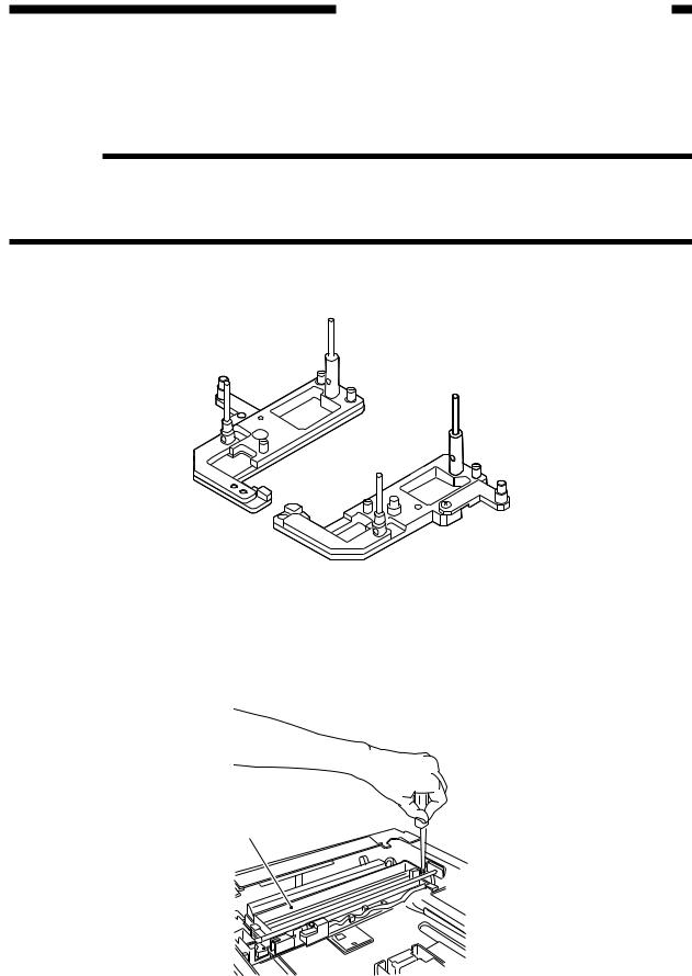
1) Fit the mirror positioning tool (FY9-3009) as shown.
Figure 2-5
2)Remove the copyboard glass.
3)Loosen the screws used to secure the cable retainer at the rear and the front of the No. 1 mirror mount [1].
[1]
Figure 2-6
2-3

CHAPTER 2 STANDARDS AND ADJUSTMENTS
4)Turn the cable drive pulley [3] so that the three shafts [2] of the mirror positioning tool for the front and the rear may be arranged as shown.
[2] |
[3] |
[2]
Figure 2-7 (rear)
[2]
[2]
Figure 2-8 (front)
2-4

CHAPTER 2 STANDARDS AND ADJUSTMENTS
5)While keeping the condition of 4), tighten the positioning screw at the rear and the front of the No. 1 mirror mount [1].
[1]
Figure 2-9 (rear)
[1]
Figure 2-10 (front)
2-5
CHAPTER 2 STANDARDS AND ADJUSTMENTS
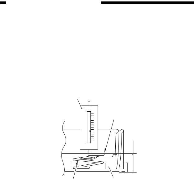
d.Checking the Force of the Cassette Spring
If the force of the spring used to hold up the holding plate of the cassette is not correct, pickup faults or the like can occur.
If a fault is suspected, check the force of the spring using a spring gauge (CK-0054), and replace the spring if it is not as indicated:
Standard: 970 ±150 g
Making Measurements
Push the spring gauge against the middle of the spring as shown, and check to make sure that the reading of the spring gauge is 970 ±150 g when the holding plate is 18 mm away from the bottom of the cassette.
Spring gauge (CK-0054)
Holding plate
18mm
Cassette spring |
Cassette |
|
Figure 2-11
2-6
CHAPTER 2 STANDARDS AND ADJUSTMENTS
e-1. Routing the Scanner Drive Cable
Wind 1.5 times. (black cable)
Wind 7.5 times. (silvercolored cable)
Figure 2-12
2-7

CHAPTER 2 STANDARDS AND ADJUSTMENTS
e-2. Routing the Scanner Drive Cable
1. Before Starting the Work
Prepare the following:
•Mirror positioning tool (FY9-3009)
•Cable clip (FY9-3017)
•Adhesive tape
1)Set the mirror positioning tool as shown.
Figure 2-13
2)Prepare about five strips of adhesive tape (each one about 20 × 50 mm).
3)Remove the copyboard glass.
4)Disconnect the connectors (J101, J131) [1] from the DC controller PCB.
[1]
Figure 2-14
2-8
CHAPTER 2 STANDARDS AND ADJUSTMENTS
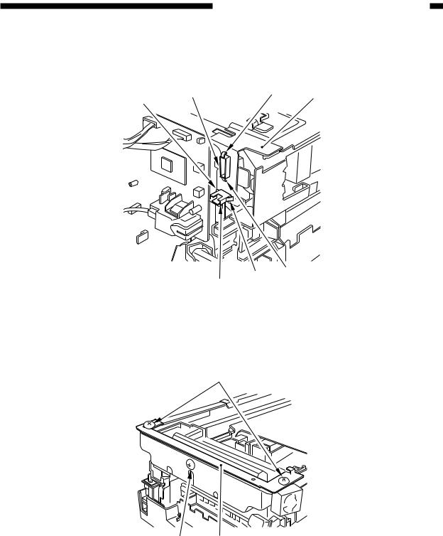
5)If the machine is equipped with an ADF, free the hook [2], and disconnect the two relay connectors [3] from the left upper stay [4].
[3] |
[2] |
[4] |
[2] |
|
|
[2] [2]
[3]
Figure 2-15
6) Remove the three screws [5], and detach the left upper stay [4].
[5]
[5][4]
Figure 2-16
2-9

CHAPTER 2 STANDARDS AND ADJUSTMENTS
7) Remove the four screws [7], and detach the lens cover [8].
[7] |
[7] |
[8]
Figure 2-17
2-10

CHAPTER 2 STANDARDS AND ADJUSTMENTS
2.Routing the Reversing Cable
1)Wind the reversing cables (silver-colored) [2] on the cable drive pulley [1] 7.5 times with the longer of the two on top; then, secure it in position with a cable clip [3].
[1]
Longer end
Shorter end
[2]
Face with a marking
Figure 2-18
[1]
[3]
[3]
Top view
Figure 2-19
2-11
CHAPTER 2 STANDARDS AND ADJUSTMENTS
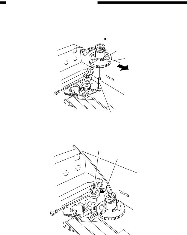
2)Put the cable drive pulley [1] into the shaft [4], and secure it in position with an E-ring [5]. When putting the cable drive pulley into the shaft, be sure that the hook is at the front.
 [5]
[5]
Hook
[1]
(front)
[4]
Figure 2-20
3) Hook the shorter end [6] on the pulley [7].
[7]
[6]
Figure 2-21
2-12
CHAPTER 2 STANDARDS AND ADJUSTMENTS
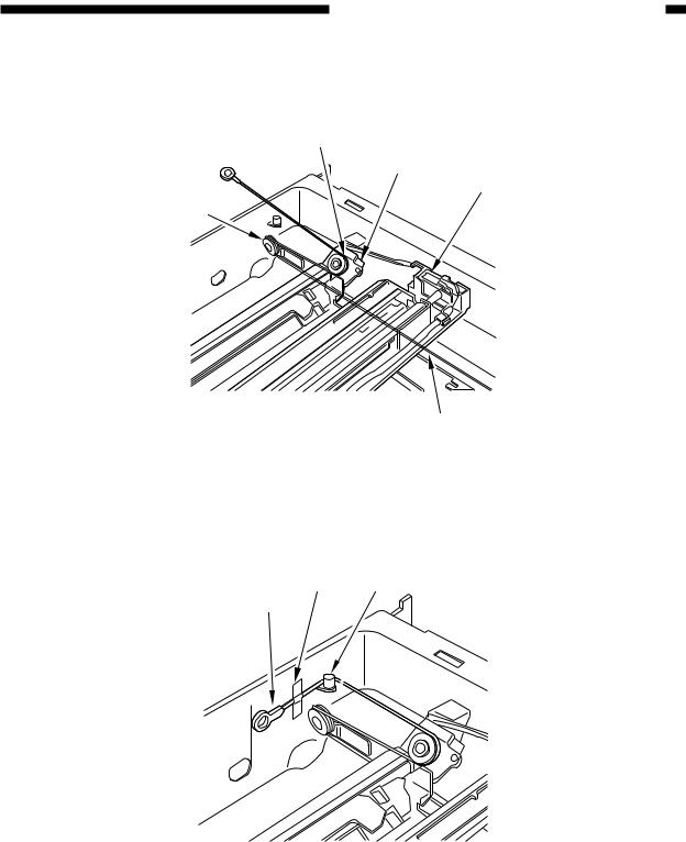
4)Lead the shorter end [6] under the No. 1 mirror mount [8] and the No. 2/3 mirror mount [9]; then, hook it on the left rear pulley [10] and the pulley [11] of the No. 2/3 mirror mount.
[11]
[9]
[8]
[10]
[6]
Figure 2-22
5)After fitting the shorter end [6] on the cable hook [12], secure its end with adhesive tape [13]. Be sure that the secured end of the cable is found where the hole in the left side plate and the tip of the cable matches.
[13][12]
[6]
Figure 2-23
2-13
Loading...