


Confidential
New Product Information
iR2200/2800/3300
Date |
: |
January 25, 2001 |
File No. |
: |
C-17-01-001 |
Released by : |
Canon Inc. |
|
|
|
OIP QA Center |
|
|
OIP TS Division |
This document precedes the Service Manual for the product in question and serves as a reference, thereby providing the Sales Companies with a good understanding of the product in advance.
Most of the contents of this document are not official and, therefore, are subject to change before the product is brought into being, making it important to bear in mind that the descriptions are true only as of the date indicated on the cover.
Yoshiaki Takase, General Manager
OIP QA Division
(TS001102)
New Product Information
Introduction to New Product Information
The document “New Product Information” replaces the Trainer’s Manual (TR) most of you are familiar with, and is the result of our efforts to provide information useful to all departments concerned in each Sales Company.
Most of the contents of this document are not official and, therefore, are subject to change before the product is brought into being, making it important to bear in mind that the descriptions are true only as of the date indicated on the cover.
The Service Manual for the product will have descriptions updated to reflect the changes that may have occurred. Kindly make arrangements so that this document is properly disposed of as soon as the Service Manual is released.
January,25, 2001
Canon Inc.
OIP QA Center
OIP QA Division

CHAPTER 1
GENERAL DESCRIPTION
COPYRIGHT © 2001 CANON INC. |
CANON iR3300/2800/2200 REV.0 JAN. 2001 |

CHAPTER 1 GENERAL DESCRIPTION
1 Specifications
1.1 Main Body
1.1.1 |
Type |
|
Item |
|
Description |
|
|
|
Body |
|
Desktop |
Copyboard |
Fixed |
|
Light source |
Xenon lamp |
|
Lens |
|
Lens array |
Photosensitive medium |
OPC drum (30-mm dia.) |
|
|
|
T01-101-01 |
1.1.2 |
Systems |
|
Item |
|
Description |
|
|
|
Reproduction |
Indirect electrostatic |
|
Charging |
AC roller |
|
Exposure |
Laser |
|
Copy density adjustment |
Auto or manual |
|
Development |
Single-component toner projection |
|
Pickup |
Auto |
Front cassette (2 cassettes) |
|
|
Retard method (about 500 sheets of 80 g/m2 paper, about 550 |
|
|
sheets of 64 g/m2 paper) |
|
Manual |
Multifeeder |
|
|
Dual process method (about 50 sheets of 80 g/m2 paper) |
Transfer |
Roller |
|
Separation |
Static eliminator (static separation) + curvature |
|
Cleaning |
Blade |
|
Fixing |
|
SURF method (plane heater and fixing film) |
|
|
T01-101-02 |
COPYRIGHT © 2001 CANON INC. |
CANON iR3300/2800/2200 REV.0 JAN. 2001 |
1-1 |

CHAPTER 1 GENERAL DESCRIPTION
1.1.3 Functions
Item |
|
|
Description |
Resolution |
Reading |
|
600dpi×600dpi |
|
Copying |
|
1200dpi×600dpi |
|
Printer output |
2400dpi×600dpi |
|
Original type |
|
|
Sheet, book 3-D object (2 kg max.) |
Maximum original size |
|
A3/279.4×431.8mm (11"×17") |
|
Reproduction ratio |
|
Direct (1:1), Reduce I (1:0.250), Reduce II (1:0.500), |
|
|
|
|
Reduce III (1:0.611), Reduce IV (1:0.707), Reduce III (1:1.414), |
|
|
|
Enlarge IV (1:2.000), Enlarge V (1:4.000), Enlarge VI (1:8.000), |
|
|
|
Zoom (1:0.250 to 8.000 in 1% increments) |
Wait time |
|
|
10 sec or less (at 20°C) |
First copy time |
|
|
5.4 sec (book mode, cassette 1, Direct, A4/LTR, text mode) |
Continuous copying |
|
999 copies max. |
|
Copy size |
|
|
|
Cassette |
|
A/B |
A3 max., A5 (vertical feed) min. |
|
|
Inch |
279.4×431.8 mm (11"×17") max., STMT (vertical feed) min. |
Manual feed |
AB |
A3 max., postcard (vertical feed) min. |
|
|
|
Inch |
279.4×431.8 mm (11"×17") max., STMT (vertical feed) min. |
Cassette 1/2 |
|
|
• Plain paper (64 to 80 g/m2):A3, B4, A4, B5, A5R, A4R, B5R, |
|
|
|
279.4×431.8mm (11"×17"), LGL, LTR, LTRR, STMT, STMTR |
|
|
|
• Tracing paper (SM-1):A3, B4, A4, B5, A4R, B5R |
|
|
|
• Colored paper (Canon-recommended):B4, A4, A4R |
Multifeeder |
|
|
• Plain paper (64 to 80 g/m2):A3, B4, A4, B5, A5R, A4R, B5R, |
|
|
|
279.4×431.8mm (11"×17"), LGL, LTR, LTRR, STMT, STMTR |
• Tracing paper (SM-1, GSN-75):A3, B4, A4, B5, A4R, B5R
• Transparency (Canon-recommended):A4, A4R, LTR, LTRR
• Colored paper (Canon-recommended):B4, A4, A4R
• Postcard: Jpn (vertical feed), double-card, 4-sheet card
• Label sheet (Canon-recommended):B4, A4, A4R, LTR, LTRR
• Thick paper (90 to 128 g/m2):A3, B4, A4, B5, A4R, B5R, LTR, LTRR
• Envelope
T01-101-03
1-2 |
COPYRIGHT © 2001 CANON INC. |
CANON iR3300/2800/2200 REV.0 JAN. 2001 |
|
CHAPTER 1 GENERAL DESCRIPTION |
|
|
Item |
Description |
|
|
Single-sided copying mode |
• Plain paper (64 to 80 g/m2):A3, B4, A4, B5, A5R, A4R, B5R, |
|
279.4×431.5mm (11"×17"), LGL, LTR, LTRR, STMT, STMTR |
|
• Tracing paper (SM-1, GSN-75):A3, B4, A4, B5, A4R, B5R |
|
• Transparency (Canon-recommended)A4, A4R, LTR, LTRR |
|
• Colored paper (Canon-recommended):B4, A4, A4R |
|
• Postcard: Jpn postcard (vertical feed), double-card, 4-sheet card |
|
• Label sheet (Canon-recommended):B4, A4, A4R, LTR, LTRR |
|
• Thick paper (90 to 128 g/m2):A3, B4, A4, B5, A4R, B5R, LTR, |
|
LTRR |
|
• Envelope |
Double-sided copying mode (automatic)
•Plain paper (64 to 80 g/m2):A3, B4, A4, B5, A5R, A4R, B5R, 279.4×431.8mm (11"×17"), LGL, LTR, LTRR, STMT, STMTR
•Colored paper (Canon-recommended):B4, A4, A4R
•Thick paper (90 to 128 g/m2):A3, B4, A4, B5, A4R, B5R, LTR, LTRR
Double-sided copying mode (multifeeder)
•Plain paper (64 to 80 g/m2):A3, B4, A4, B5, A5R, A4R, B5R, 279.4×431.8mm (11"×17"), LGL, LTR, LTRR, STMT, STMTR
•Colored paper (Canon-recommended):B4, A4, A4R
•Postcard: Jpn (vertical feed), double-card, 4-sheet card
•Thick paper (90 to 128 g/m2):A3, B4, A4, B5, A4R, B5R, LTR, LTRR
T01-101-04
COPYRIGHT © 2001 CANON INC. |
CANON iR3300/2800/2200 REV.0 JAN. 2001 |
1-3 |

CHAPTER 1 GENERAL DESCRIPTION
Item |
|
Description |
Cassette |
Claw |
None |
|
Capacity |
55 mm deep (approx.; about 500 sheets of 80 g/m2 paper) |
Hard disk |
|
6.4GB (*1) |
Non-image width |
Leading edge |
Direct, Enlarge/Reduce:4.0±1.5/-1.0mm <4.5±1.8mm>*2 |
|
Trailing edge |
Direct, Enlarge/Reduce:2.0±1.5mm <2.0±1.8mm>*2 |
|
Left/right (1st side) |
Direct, Enlarge/Reduce:2.5±1.5mm <2.5±2.0mm>*2 |
Auto clear |
|
Yes (2 min standard; may be changed in 1-min increments |
|
|
between 0 and 9 min) |
Auto power-off |
|
Yes |
Low-power mode |
|
Yes (15 min standard; may be changed in user mode to |
|
|
10, 15, 20, 30, 40, 50, 60, 90 min, 2, 3, or 4 hr) |
Sleep mode |
|
Yes (60 min standard; may be changed in user mode to |
|
|
10, 15, 20, 30, 40, 50, 60, 90 min, 2, 3, or 4 hr) |
|
|
Yes (-10% standard; may be changed in user mode to - |
|
|
10%, -25%, -50%, or no return (0%)) |
Accessory |
|
• DADF-H1 |
|
|
• Copyboard Cover Type-E |
|
|
• Copyboard-D1 |
|
|
• Copy Tray-F1 |
|
|
• Saddle Finisher-G1 |
|
|
• Puncher Unit-G1 |
|
|
• Finisher-J1 |
|
|
• Inner 2-Way Tray-A1 |
|
|
• Side Paper Deck-L1 |
|
|
• 2-cassette Pedestal-W1 |
|
|
• Options Power Supply-B1 (required for SF, PD) |
|
|
• Cassette Heater Kit-16N |
|
|
• Control Card-IV |
|
|
• Network LIPS Printer Kit-A1 (100V model only) |
|
|
• Network Multi-PDL Printer Kit-A1 (120/230V model |
|
|
only) |
*1:The HDD that comes with the machine and the HDD that is made available as a service part may have different memory sizes; however, the area of the HDD used by the machine will be the same, and either may be used without a problem.
*2:The values within parentheses indicate when the DADF is used.
T01-101-05
The above specifications are subject to change for product improvement.
1-4 |
COPYRIGHT © 2001 CANON INC. |
CANON iR3300/2800/2200 REV.0 JAN. 2001 |
|
|
CHAPTER 1 GENERAL DESCRIPTION |
|
|
|
1.1.4 Others |
|
|
Item |
|
Description |
|
|
|
Operating environment |
Temperature range |
15° to 30°C |
|
Humidity range |
5 to 80% |
|
Atmospheric pressure |
810.6 to 1013.3 hpa (0.8 to 1.0 atm) |
Power supply |
|
E201 |
|
|
LQHxxxxx |
100V (50/60Hz) |
|
LQJxxxxx |
|
|
NRFxxxxx |
120V (50/60Hz) |
|
NRGxxxxx |
|
|
PKMxxxxx |
220V/60Hz |
|
PKKxxxxx |
230V (50/60Hz) |
|
PKLxxxxx |
|
|
QCWxxxxx |
|
|
RBZxxxxx |
|
|
SCKxxxxx |
|
|
TBZxxxxx |
|
|
UFMxxxxx |
Power consumption |
Maximum |
E201: 1.5 kW or less |
|
Standby |
E201: 282 W (approx.; reference only) |
|
Continuous |
E201: 995 W (approx.; reference only) |
Noise |
|
Sound power level (Impulse mode) |
|
Copying |
E201: 66 dB or less, E202: 71 dB or less |
|
Standby |
E201: 40 dB or less, E202: 50 dB or less |
Ozone |
|
0.01 ppm or less avg., 0.02 ppm or less max. |
Dimensions (mm) |
(iP-Lite) |
565 (W) × 678 (D) × 1020 (H) |
|
(iP-Std) |
565 (W) × 678 (D) × 1040 (H) |
Weight |
|
80 kg (approx.) |
Consumables |
Copy paper |
Keep wrapped to protect against humidity. |
Toner |
|
Keep away from direct sunshine, and keep at |
|
|
40°C/85% or less. |
T01-101-06
COPYRIGHT © 2001 CANON INC. |
CANON iR3300/2800/2200 REV.0 JAN. 2001 |
1-5 |

CHAPTER 1 GENERAL DESCRIPTION
Reproduction mode |
Side |
Paper size |
copies /min (1-to-N) |
|
|
|
|
E201 |
E202 |
|
|
|
|
|
Direct |
A3 (297×420mm) |
A3 |
- |
16 |
|
A4 (210×297mm) |
A5 |
- |
- |
|
A5 (149×210mm) |
A4 |
22 |
33 |
|
B4 (257×364mm) |
B4 |
- |
14 |
|
B5 (182×257mm) |
B5 |
- |
28 |
|
A4R (297×210mm) |
A4R |
- |
- |
|
B5R (257×182mm) |
B5R |
- |
- |
|
A5R (210×149mm) |
A5R |
- |
- |
Reduce II |
|
|
|
|
(50.0%) |
A3 → A5R |
A5R |
- |
- |
III |
|
|
|
|
(61.1%) |
A3 → B5R |
B5R |
- |
- |
IV |
|
|
|
|
(70.7%) |
B4 → B5R |
B5R |
- |
- |
V |
A3 → A4R |
A4R |
- |
- |
(81.6%) |
B4 → A4R |
A4R |
- |
- |
VI |
B5R → A5R |
A5R |
- |
- |
(86.5%) |
A4 → B5 |
B5 |
- |
- |
|
A3 → B4 |
B4 |
- |
- |
Enlarge IV |
|
|
|
|
(200.0%) |
A5R → A3 |
A3 |
- |
- |
III |
|
|
|
|
(141.4%) |
A4R → A3 |
A3 |
- |
- |
II |
B5R → B4 |
B4 |
- |
- |
(122.4%) |
A4R → B4 |
B4 |
- |
- |
I |
A5 → B5 |
B5 |
- |
- |
(115.4%) |
B4 → A3 |
A3 |
- |
- |
|
B5 → A4 |
A4 |
- |
- |
Delivery by copier, Auto paper select ON, Auto density, Non-sort, Deck/Cassette
T01-101-07 Copying Speeds (copier only)
1-6 |
COPYRIGHT © 2001 CANON INC. |
CANON iR3300/2800/2200 REV.0 JAN. 2001 |

CHAPTER 1 GENERAL DESCRIPTION
Reproduction mode |
Size |
|
(1toN) |
|
|
|
|
E201 |
E202 |
|
|
|
|
|
Direct |
279.4×431.8mm |
279.4×431.8mm |
- |
16 |
|
(11"×17") |
(11"×17") |
|
|
|
LTR |
LTR |
22 |
33 |
|
LGL |
LGL |
- |
14 |
|
LTRR |
LTRR |
- |
- |
|
STMTR |
STMTR |
- |
- |
Reduce II |
279.4×431.8mm |
STMTR |
- |
- |
(50.0%) |
(11"×17") → STMTR |
|
|
|
III |
279.4×431.8mm |
LTRR |
- |
- |
(64.7%) |
(11"×17") → LTRR |
|
|
|
IV |
279.4×431.8mm |
LGL |
- |
- |
(73.3%) |
(11"×17") → LGL |
|
|
|
V |
LGL → LTRR |
LTRR |
- |
- |
(78.6%) |
|
|
|
|
Enlarge IV |
STMTR* → |
279.4×431.8mm |
- |
- |
(200.0%) |
279.4×431.8mm |
(11"×17") |
|
|
|
(11"×17") |
|
|
|
III |
LTRR → |
279.4×431.8mm |
- |
- |
(129.4%) |
279.4×431.8mm |
(11"×17") |
|
|
|
(11"×17") |
|
|
|
II |
LGL → |
279.4×431.8mm |
- |
- |
(121.4%) |
279.4×431.8mm |
(11"×17") |
|
|
|
(11"×17") |
copies/min |
|
|
|
Paper size |
|
|
|
*STMTR cannot be used as an original.
Delivery by copier, Auto paper select ON, Auto density, Non-sort, Deck/Cassette
T01-101-08 Copying Speeds (copier only)
The above specifications are subject to change for product improvement.
COPYRIGHT © 2001 CANON INC. |
CANON iR3300/2800/2200 REV.0 JAN. 2001 |
1-7 |
CHAPTER 1 GENERAL DESCRIPTION
1.2 Side Paper Deck-L1
Item |
Description |
|
Pickup method |
Retard |
|
Paper accommodation |
Front loading |
|
Paper type (horizontal feed only) |
Plain paper (65 to 80 g/m2): A4, B5, LTR |
|
|
Colored paper (Canon-recommended): A4 |
|
Capacity |
2,500 sheets (approx.; 80 g/m2 paper) |
|
Serial number |
A4 type:XCQxxxxx |
LTR type: XCRxxxxx |
Paper size switch |
By size guide plate/in service mode |
|
Dimensions |
324 (W) × 591 (D) × 432 (H) mm |
|
Weight |
30 kg (approx.) |
|
Power supply |
None (DC power supplied by accessories power supply of |
|
|
host machine) |
|
Operating conditions |
Same as host machine |
|
T01-200-01
The above specifications are subject to change for product improvement.
1-8 |
COPYRIGHT © 2001 CANON INC. |
CANON iR3300/2800/2200 REV.0 JAN. 2001 |

CHAPTER 1 GENERAL DESCRIPTION
2 Names of Parts
2.1 External View
[1]
[2]
[3]
[7]
[4] |
[5] |
[6]
[1]ADF
[2]Original tray
[3]Control panel
[4]Front cover
[5]Cassette 1
[6]Cassette 2
[7]Delivery tray
[8]Multifeeder
 [8]
[8]
[9]
[9]Right lower cover
[10]DIMM ROM replacement cover
[11]Network card slot
[12]Parallel connector
[13]Extension board slot
[14]Main power switch
[15]Cassette heater switch
F01-201-01 External View 1
COPYRIGHT © 2001 CANON INC. |
CANON iR3300/2800/2200 REV.0 JAN. 2001 |
1-9 |

CHAPTER 1 GENERAL DESCRIPTION
[1]
[2]
[3] |
[5] |
|
[4]
[7]
[6]
[1] |
Copyboard glass |
[5] |
Developing assembly releasing |
[2] |
DADF reading glass |
|
lever |
[3] |
Left cover |
[6] Feeding assembly releasing lever |
|
[4] Left lower rear cover (waste toner |
[7] |
Duplex feeding assembly releas- |
|
|
case cover) |
|
ing lever |
F01-201-02 External View 2
1-10 |
COPYRIGHT © 2001 CANON INC. |
CANON iR3300/2800/2200 REV.0 JAN. 2001 |

CHAPTER 1 GENERAL DESCRIPTION
2.2 Cross Section
F01-202-01 Cross Section
COPYRIGHT © 2001 CANON INC. |
CANON iR3300/2800/2200 REV.0 JAN. 2001 |
1-11 |

CHAPTER 1 GENERAL DESCRIPTION
[1]DADF reading glass
[2]No. 1 mirror
[3]Scanning lamp
[4]Copyboard glass
[5]Fixing assembly
[6]Feeding assembly
[7]Laser mirror 3
[8]Laser mirror 2
[9]Laser mirror 1
[10]Drum cleaner assembly
[11]Primary charging assembly
[12]Photosensitive drum
[13]Laser mirror 4
[14]CCD unit
[15]Laser unit
[16]Dust-proofing glass
[17]Developing cylinder
[18]Pre-transfer charging assembly
[19]Multifeeder pickup roller
[20]Multifeeder separation roller
[21]Registration roller
[22]Transfer roller
[23]Static eliminator
[24]Cassette 1 pickup roller
[25]Cassette 1 feeding roller
[26]Cassette 1 separation roller
[27]Cassette 2 pickup roller
[28]Cassette 2 feeding roller
[29]Cassette 2 separation roller
[30]Cassette 1
[31]Cassette 2
[32]Lower fixing roller
[33]Inside delivery roller
[34]Outside delivery roller
[35]Upper fixing roller
[36]No. 3 mirror
[37]No. 2 mirror
T01-202-01
1-12 |
COPYRIGHT © 2001 CANON INC. |
CANON iR3300/2800/2200 REV.0 JAN. 2001 |

CHAPTER 1 GENERAL DESCRIPTION
3. System Configuration
3.1 Functional Construction
The machine may be broadly divided into the following six functional blocks:
|
|
|
Various |
|
|
|
|
networks or public |
|
Original |
|
telephone |
|
|
|
network |
|
||
Optical path |
Original |
|
|
|
illumination |
|
Various |
|
|
|
Control |
|
||
|
|
|
||
|
Original |
accessory |
|
|
CCD PCB |
panel |
|
||
boards |
|
|||
|
Exposure Block |
|
|
|
Reader controller |
|
|
|
|
PCB |
Main controller PCB |
|
||
|
|
|
||
|
|
Image Processing Block |
HDD |
|
|
|
|
||
DC controller |
|
|
|
|
PCB |
|
|
|
|
DC power |
Control |
|
supply PCB |
||
Block |
Laser driver PCB
Laser scanner |
Laser |
Exposure Block
|
|
Charging |
|
|
|
|
|
|
|
Photo- |
|
|
|
|
|
Cleaning |
sensitive |
Development |
|
|
|
|
|
|
drum |
|
|
|
Fixing |
|
Separation |
Transfer |
Image Formation Block |
|
Delivery |
Feeding |
Pickup |
Multi- |
|||
tray |
|
|
|
|
control |
feeder |
Lower feeding assembly |
Side paper |
|
|
Cassette 1 |
deck |
|
(accessory) |
Cassette 2 |
Pickup/Feeding Block |
|
F01-301-01
COPYRIGHT © 2001 CANON INC. |
CANON iR3300/2800/2200 REV.0 JAN. 2001 |
1-13 |

CHAPTER 1 GENERAL DESCRIPTION
3.2 Outline of the Electrical Circuitry
3.2.1 Construction of the Electrical Circuit
The major electrical mechanisms of the machine are controlled by the following PCBs:
[1]Man controller PCB; controls the system as a whole, processes images
[2]DC controller PCB; controls the printer unit, controls the finisher communication
[3]Reader controller PCB; controls the reader unit, controls the DADF communication
|
|
|
|
|
|
|
|
|
|
|
CCD |
PCB |
|
|
ADF |
|
|
|
|
|
LA2 |
|
|
|
IC5025 |
(CPU) |
|
|
IC5016 |
(ROM) |
IC5008 |
IC5009 |
(RAM) |
|
IC5027 |
(EEPROM) |
|
IC5021 |
(IPC comm- |
unication 2) |
Reader |
|
controller PCB |
|
Inverter |
PCB |
|
|
|
|
|
|
|
|
M3 |
Scanner |
motor |
||||||||||||||
Accessory boards |
|
IC1010 |
(CPU) |
Maincontroller PCB |
|
|
IC125 (CPU) |
IC104,105 |
IC109,110 |
IC127,130 (EEPROM) |
|
|
Main |
power |
supply |
PCB |
|
|
|||||
|
|
|
|
|
Drum |
sensor PCB |
|
|
|||||||||||||||
|
|
|
|
|
|
PCB (RAM) |
|
|
|
|
IC121 DIMM/ |
IC122 ROM |
(RAM) (IC117) |
PCBcontrollerDC |
|
|
Composite |
power |
supply |
PCB |
|
|
|
Hard disk drive |
(HDD) |
|
Control |
panel |
|
IC120 |
|
|
|
LaserBD |
supply |
PCB |
|
|
|||||||||
|
|
|
-(DIMM |
ROM) |
|
|
|
|
|
|
|
|
|
|
Accessories |
power |
|
|
|
|
|||
|
|
|
IC6501 |
(CPU) |
|
• Finisher |
(accessory) (IPC comm- |
DC loads unication 2) • Clutch • Solenoid • Motor |
• Sensor • Fan • Etc. |
Pickup |
PCB PCB drive PCB |
|
|
||||||||||
|
|
|
|
|
|
|
|
|
F01-302-01 |
|
|
|
|
|
|
|
|
|
|||||
1-14 |
COPYRIGHT © 2001 CANON INC. |
CANON iR3300/2800/2200 REV.0 JAN. 2001 |

CHAPTER 1 GENERAL DESCRIPTION
3.3 Inputs to and Outputs from the Major PCBs
3.3.1 Wiring Diagram of the Major PCBs
Potential |
|
|
|
|
|
|
|
|
J103 |
|
|||||
control |
|
|
|
|
|
|
|
|
|
|
|
|
|
|
|
PCB |
|
J3 |
|
|
|
|
|
|
|
|
|
|
|||
|
|
|
|
|
|
|
|
|
|
|
|
|
|
|
|
|
|
|
|
|
|
|
|
|
|
|
|
|
|
|
|
Duplex |
|
|
|
|
|
|
|
|
J107 |
|
|||||
driver |
|
|
|
|
|
|
|
|
|
|
|
|
|
|
|
PCB |
J2302 |
|
|
|
|
|
|
|
|||||||
|
|
|
|
|
|
|
|
|
|
|
|
|
|
|
|
|
|
|
|
|
|
|
|
|
|
|
|
|
|
|
|
Laser scanner |
|
|
|
|
|
J116 |
|
||||||||
motor |
|
|
|
|
|
|
|
|
|
|
|
|
|
|
|
M15 |
|
|
|
|
|
|
|
|
|
|
|
||||
J2511 |
|
|
|
|
|
|
|
||||||||
|
|
|
|
|
|
|
|
|
|
|
|
|
|
|
|
|
|
|
|
|
|
|
|
|
|
|
|
|
|
|
|
Laser drive |
|
|
|
|
|
J121 |
|
||||||||
|
|
|
|
|
|
|
|
|
|
|
|
||||
PCB |
|
|
|
|
|
|
|
|
|
|
|
|
|
|
|
|
J2501 |
|
|
|
|
|
|
|
|||||||
|
|
|
|
|
|
|
|
|
|||||||
|
|
|
|
|
|
|
|
|
|
|
|
|
|
|
|
|
|
|
|
|
|
|
|
|
J120 |
|
|||||
BD PCB |
|
|
|
|
|
|
|
|
|
|
|
|
|
|
|
|
J2701 |
|
|
|
|
|
|
|
|||||||
|
|
|
|
|
|
|
|
|
|
|
|
|
|
|
|
|
|
|
|
|
|
|
|
|
|
|
|
|
|
|
|
DC power |
|
|
|
|
|
|
|
|
J101 |
|
|||||
|
|
|
|
|
|
|
|
|
|
|
|
|
|
|
|
supply PCB |
|
|
|
|
|
|
|
|
|
|
|
|
DC |
||
J4003 |
|
|
|
|
|
|
|||||||||
|
|
|
|
|
|
|
|
||||||||
|
|
|
|
|
|
|
|
|
|
|
|
controller |
|||
|
|
|
|
|
|
|
|
|
J102 |
||||||
HVT PCB |
|
|
|
|
|
|
|
|
|
|
|
|
|
|
PCB |
|
|
|
|
|
|
|
|
|
|
||||||
|
|
|
|
|
|
|
|
|
|
|
|
|
|
|
|
|
|
|
|
J4502 |
|
|
|
|
|
|
|
||||
|
|
|
|
|
|
|
|
|
|
|
|
|
|
|
|
|
|
|
|
|
|
|
|
|
J113 |
|
|||||
Environment |
|
|
|
|
|
||||||||||
|
|
|
|
|
|
|
|
|
|
|
|
||||
sensor PCB |
|
J8492 |
|
|
|
|
|
|
|||||||
|
|
|
|
|
|
|
|||||||||
|
|
|
|
|
|
|
|
|
|
|
|
|
|
|
|
|
|
|
|
|
|
|
|
|
|
|
|
|
|
|
|
Cassette 3 |
|
|
|
J113 |
|
|
|
|
|
|
|||||
paper level |
|
|
|
|
|
|
|
|
|
|
|
|
|||
detection |
|
|
|
|
|
|
|
|
|
|
|
|
|
|
|
|
J806 |
|
|
|
|
|
|
|
|
|
|||||
PCB |
|
|
|
|
|
|
|
|
|
|
|||||
|
|
|
|
|
|
|
|
|
|
|
|
|
|
|
|
|
|
|
|
|
|
|
J113 |
|
|
|
|
|
|
||
Cassette 4 |
|
|
|
|
|
|
|
|
|
||||||
paper level |
|
|
|
|
|
|
|
|
|
|
|
|
|||
detection |
|
|
|
|
|
|
|
|
|
|
|
|
|
|
|
PCB |
|
|
J810 |
|
|
|
|
|
|
|
|
|
|||
|
|
|
|
|
|
|
|
|
|
|
|
|
|
|
|
|
|
|
|
|
|
|
|
|
|
|
|
|
|
|
|
AC driver |
|
|
|
|
|
|
J102 |
|
|
|
|
|
|
||
|
|
|
|
|
|
|
|
|
|
|
|
|
|
|
|
PCB |
|
|
|
|
|
|
|
|
|
|
|
|
|
|
|
|
J2052 |
|
|
|
|
|
|
|
|||||||
|
|
|
|
|
|
|
|
|
|||||||
|
|
|
|
|
|
|
J104 |
|
|||||||
Motor |
|
|
|
|
|
|
|
|
|
|
|
|
|
|
|
|
|
J2101 |
|
|
|
|
|
|
|
||||||
driver |
|
|
|
|
|
|
J105 |
|
|
|
|
|
|
||
|
|
|
|
|
|
|
|
|
|
|
|
||||
PCB |
|
|
|
|
|
|
|
|
|
|
|
|
|
|
|
|
|
|
|
J2108 |
|
|
|
|
|
|
|
||||
|
|
|
|
|
|
|
|
|
|
|
|
|
|
|
|
|
|
|
|
|
|
|
|
|
|
|
|
|
|
|
|
|
|
J6604 |
|
||
LCD panel |
J6503 |
|
J6502 |
|
|
J6509 |
|
||||
(LCD) |
|
|
|||
|
|
|
|
||
|
J6507 Control |
|
J6601 |
|
|
|
J6504 |
Keypad |
|||
InverterJ956 |
panel |
||||
|
|
PCB |
|||
CPU PCB |
J6602 |
||||
PCB |
|
|
|
||
J6506 |
J6501 |
|
|||
|
|
||||
|
|
|
J6603 |
|
|
|
|
J6508 |
|
||
J122
Hard disk
J1551
Control
Card-IV (accessory)
J1532
Copy Data Controller (accessory)
J1530
|
J6605 |
J6505 |
J6801 |
J1012 |
J1018 |
J1015 |
|
J1017
Controller J5004
assembly
J1060 J1014
|
Reader |
|
controller |
J1022 |
PCB |
CCD/AP |
J5003 |
|
|
PCB J6002 |
|
Scanner |
J5011 |
motor M3 |
|
Inverter |
J5007 |
|
|
PCB J5101 |
|
Note: The |
in the diagram indicates connection between PCBs, NOT the flow of signals. |
F01-303-01
COPYRIGHT © 2001 CANON INC. |
CANON iR3300/2800/2200 REV.0 JAN. 2001 |
1-15 |
CHAPTER 1 GENERAL DESCRIPTION
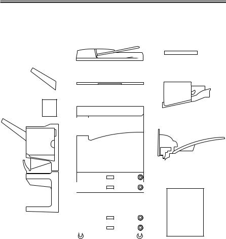
3.4 Configuration with Accessories
3.4.1 Accessories for Original/Paper Feeding
|
[1] |
[3] |
|
|
|
[4] |
[2] |
[7] |
|
[6]
[5]
[8]
[9]
[10]
|
|
|
|
|
|
|
|
|
|
|
|
|
|
|
|
|
|
|
|
|
|
|
|
|
|
|
|
[1] |
DADF-H1 |
[7] |
Finisher-J1 |
|||
[2] |
Copyboard Cover Type-E |
[8] |
Inner 2-Way Tray-A1 |
|||
[3] |
Copyboard-D1 |
[9] |
Side Paper Deck-L1 |
|||
[4] |
Copy Tray-F1 |
|
|
[10] 2-Cassette Pedestal-W1 |
||
[5] |
Saddle Finisher-G1 |
|
|
[11] Options Power supply-N1 |
||
[6] |
Puncher Unit-E1 |
|
|
|
(required when [5] or [9] is used) |
|
|
|
F01-304-01 |
|
|
||
1-16 |
COPYRIGHT © 2001 CANON INC. |
CANON iR3300/2800/2200 REV.0 JAN. 2001 |

CHAPTER 1 GENERAL DESCRIPTION
3.4.2 Accessory Boards
LIPS Printer Kit-B1
|
|
|
|
|
|
|
|
|
|
|
|
|
|
|
|
|
|
|
|
|
|
|
|
|
|
|
|
|
|
|
|
|
LPS |
|
|
|
Relay |
|
|
Network |
|
|
|||
|
|
|
|
|
|
|
|
|
PCB |
|
|
|
PCB |
|
|
|
PCB |
|
|
|||
|
|
|
|
|
|
|
|
|
|
|
|
|
|
|
|
|
|
|
|
|
|
|
|
|
|
|
|
|
|
|
|
|
|
|
|
|
|
|
|
|
|
|
|
|
|
|
|
|
|
|
|
|
|
Network Multi-PDL |
|
|
|
|
|
|||||||||
|
|
|
|
|
|
|
|
Printer Kit-B1 |
|
|
|
|
|
|||||||||
|
|
|
|
|
|
|
|
|
|
|
|
|
|
|
|
|
|
|
|
|||
|
|
|
|
|
|
|
|
|
|
|
|
|
|
|
|
|
||||||
|
|
|
|
|
|
|
|
|
RIP1 |
|
|
Relay |
|
Network |
|
|
||||||
|
|
|
|
|
|
|
|
|
|
|||||||||||||
|
|
|
|
|
|
|
|
|
PCB |
|
|
PCB |
|
|
PCB |
|
|
|||||
|
|
|
|
|
|
|
|
|
|
|
|
|
|
|
|
|
|
|
|
|
|
|
|
|
|
|
|
|
|
|
|
|
|
|
|
|
|
|
|
|
|
|
|
|
|
|
|
|
|
|
|
|
|
|
|
|
|
Network |
|
|
|
|
|
|||||
|
|
|
|
|
|
|
|
|
|
|
|
|
|
|
|
|
||||||
|
|
|
|
|
|
|
|
|
|
|
|
|
|
|
|
|||||||
|
|
|
|
|
|
|
|
|
|
|
|
|
|
|
|
|
|
|
|
|
||
|
|
|
|
|
|
|
|
|
|
|
|
|
Network |
|
|
|
|
|
|
|||
|
|
|
|
|
|
|
|
|
|
|
|
|
|
|
|
|
|
|
||||
|
|
|
|
|
|
|
|
|
|
|
|
|
|
PCB |
|
|
|
|
|
|
||
|
|
|
|
|
|
|
|
|
|
|
|
|
|
|
|
|
|
|
|
|||
|
|
|
|
|
|
|
|
|
Relay PCB |
|
Token Ring |
|
||||||||||
|
|
|
|
|
|
|
|
|
|
|
||||||||||||
|
|
|
|
|
|
|
|
|
|
|
||||||||||||
|
|
|
|
|
|
|
|
|
|
|
|
|
|
|
|
|||||||
|
|
|
|
|
|
|
|
|
|
Relay |
|
|
TokenRing |
|
|
|
||||||
|
|
|
|
|
|
|
|
|
|
PCB |
|
|
PCB |
|
|
|||||||
|
|
|
|
|
|
|
|
|
|
|
|
|
|
|
|
|
|
|||||
|
|
|
|
|
|
|
|
|
|
|
|
|
|
|
|
|
|
|
|
|
|
|
|
|
|
|
|
|
|
|
|
|
Super G3 FAX |
|
|
|
|
|
|||||||
|
|
|
|
|
|
|
|
|
|
Board-J1 |
|
|
|
|
|
|||||||
|
|
|
|
|
|
|
|
|
|
|
|
|
|
|
|
|
|
|||||
|
|
|
|
|
|
|
|
|
|
|
|
|
|
|
|
|
|
|||||
|
|
|
|
|
|
|
|
|
|
Multiport Kit-B1 |
|
|
|
|
|
|||||||
|
|
|
|
|
|
|
|
|
|
|
|
|
|
|
|
|
|
|
|
|
|
|
G4 FAX Board-B1
F01-304-02
Ethernet
network
TokenRing
network
Public telephone network
ISDN network
COPYRIGHT © 2001 CANON INC. |
CANON iR3300/2800/2200 REV.0 JAN. 2001 |
1-17 |
CHAPTER 2
ORIGINAL EXPOSURE SYSTEM
COPYRIGHT © 2001 CANON INC. |
CANON iR3300/2800/2200 REV.0 JAN. 2001 |

CHAPTER 2 ORIGINAL EXPOSURE SYSTEM
1. Outline of Operations
1.1 Outline
The original exposure system has the following major functions:
Item |
Description |
|
Original illumination |
Xenon tube |
|
Original scanning |
In Book mode: by moving scanner |
|
|
With ADF in use: by fixed No. 1 mirror base at stream reading po- |
|
|
sition |
|
scanner position detection |
Scanner HP sensor (PS400) |
|
Reproduction ratio (zoom) |
[1] Copyboard Mode (25% to 800%) |
|
|
Main scanning direction: image processing by controller assembly |
|
|
Sub scanning direction: |
for a ratio of 50% or higher, changing |
|
|
scanning speed of No. 1 mirror; for a |
|
|
ratio of lower than 50% and 400% or |
|
|
higher, chaining scanning speed and im- |
|
|
age processing |
|
[2] ADF Mode (25% to 400%) |
|
|
Main scanning direction: image processing by controller assembly |
|
|
Sub scanning direction: |
for a ratio of 50% or higher, changing |
|
|
original feeding speed; for a ratio of |
|
|
lower than 50% and 200% or higher, |
Scanner drive control |
No. 1/No. 2 mirror base: control by stepping motor (M400) |
|
Lens |
Lens array, fixed type |
|
Scanning lamp control |
[1] Control of activation by inverter circuit |
|
|
[2] Control for error detection |
|
Original size detection |
[1] In Book Mode |
|
|
Sub scanning direction: by reflection type sensor |
|
|
Main scanning direction: by CCD |
|
[2] With ADF in Use By ADF
COPYRIGHT © 2001 CANON INC. |
CANON iR3300/2800/2200 REV.0 JAN. 2001 |
2-1 |

CHAPTER 2 ORIGINAL EXPOSURE SYSTEM
1.2 Changing the Reproduction Ratio (Zoom)
[1]In Copyboard Mode
If for a reproduction ratio of 25% to 800%, the speed of the scanner is changed.
[2]With ADF in Use
If for a reproduction ratio of 25% to 400%, the speed of the movement of the original is changed.
1.2.1 Changing the Reproduction Ratio in Main Scanning Direction
For scanning direction, reading is always at 100% in both copyboard and ADF modes; the ratio is changed in the course of data processing in the main controller assembly.
To reduce, data units are skipped. To enlarge, data units are repeated.
1.2.2 Changing the Reproduction Ratio in Sub Scanning Direction
For sub scanning direction, the speed of the scanner/movement of the original is changed. However, for a reduction between 25% and 49% and enlargement between 401% and 800%, data processing in the main controller assembly is also used in combination.
[1]For enlargement, the speed of the mirror/original is reduced from that used in Direct: e.g., at 200%, the speed is 1/2 of the speed used in Direct.
[2]For reduction between 50% and 99%, the speed of the mirror/original is increased; e.g., at 50%, the speed is twice as high as that used in Direct.
(speed ratio)
2
1
1/2 1/4
(reproduction ratio)
50% |
100% |
200% |
400% |
F02-102-01
[3]For a reduction between 25% and 49%, image data read at 50% to 98% is subjected to skipping (1/2) in the main controller assembly.
[4]For an enlargement between 401% and 800%, image data read at 200% to 400% is subjected to repeating (doubling) in the main controller assembly.
2-2 |
COPYRIGHT © 2001 CANON INC. |
CANON iR3300/2800/2200 REV.0 JAN. 2001 |

CHAPTER 3
LASER EXPOSURE SYSTEM
COPYRIGHT © 2001 CANON INC. |
CANON iR3300/2800/2200 REV.0 JAN. 2001 |

CHAPTER 3 LASER EXPOSURE SYSTEM
1 Outline of Operations
1.1 Outline
Part 2>Chapter 4>1.1 “Outline of Laser Exposure”
The reader controller PCB serves to read image signals from the CCD and send image signals to the main controller assembly. The video signals from the main controller assembly are converted by the DC controller PCB into laser drive signals, and are turned into laser intensity signals to suit signal levels by the laser driver PCB.
The laser intensity signals are used to cause the laser unit to generate a laser beam, which is directed to the photosensitive drum for the formation of latent static images.
The laser beam is also used for blank exposure to create non-image areas.
Item |
Description |
Laser intensity control |
Laser power auto control (APC control) |
Laser scanning |
By semiconductor laser |
Synchronization control |
Main scanning direction: control by BD signal |
|
Sub scanning direction: control by image leading edge signal |
Laser scanner motor control |
Constant speed rotation control |
|
T03-101-01 |
COPYRIGHT © 2001 CANON INC. |
CANON iR3300/2800/2200 REV.0 JAN. 2001 |
3-1 |

CHAPTER 3 LASER EXPOSURE SYSTEM
F03-101-01 shows the major components for the laser exposure system; the machine’s laser scanning is performed by means of a 6-facet polygon mirror and a single-beam laser unit:
Laser unit |
Cylindrical lens |
Polygon mirror (6-faceted)
Laser scanner motor
BD mirror 
|
Collimating lens |
|
BD PCB |
|
Laser mirror |
Photosensitive drum |
|
|
F03-101-01 External View |
Component |
Description |
Laser semiconductor |
Visible laser light (about 6760 nm), single-beam |
Laser scanner motor (M10) |
DC brush-less motor, constant speed control |
Polygon mirror |
6-faceted |
BD mirror/BD PCB |
Laser beam detection |
Laser driver PCB |
Laser activation control |
DC controller PCB |
Laser scanner motor rotation control |
T03-101-02 List of Components
3-2 |
COPYRIGHT © 2001 CANON INC. |
CANON iR3300/2800/2200 REV.0 JAN. 2001 |

CHAPTER 3 LASER EXPOSURE SYSTEM
1.2 Sequence of Operations (laser exposure system)
Main power switch ON/sleep mode OFF Original set/ADF opened
Start key ON
180˚C
|
|
AINTR |
|
STBY |
INTR |
|
LSTR |
|
STBY |
|||||
|
|
|
8 sec |
|
|
|
|
|
|
|
|
* |
|
|
|
|
|
|
|
|
|
|
|
||||||
Laser scanner |
|
|
|
|
|
|
|
|
|
|||||
|
|
|
|
|
|
|
|
|
|
|||||
motor |
|
|
|
|
|
|
|
|
|
|
|
|||
|
|
|
|
|
|
|
|
|
|
|
||||
Image leading |
|
|
|
|
|
|
|
|
|
|
||||
edge signal |
|
|
|
|
|
|
|
|
|
|
||||
|
|
|
|
|
|
|
|
|
|
|||||
Laser
BD signal
*: If silent mode (in user mode) is selected, the motor stops after a specific period of time.
F03-102-01 Basic Sequence of Operations
COPYRIGHT © 2001 CANON INC. |
CANON iR3300/2800/2200 REV.0 JAN. 2001 |
3-3 |

CHAPTER 3 LASER EXPOSURE SYSTEM
2 Generating Sync Signals
2.1 Outline
Part 2>Chapter 4>2 “Generating BD Signals”
The BD signal used to synchronize the video signals in laser scanning direction is generated by the BD PCB with reference to the laser beam reflected by the BD mirror mounted in the path of the laser beam.
The edge of paper re-picked in double-sided mode is detected by the horizontal registration sensor to measure the displacement to the rear/front. Based on the measurement, the timing of laser activation is changed with reference to the BD signal so that the image will be placed at a specific position on the paper without fail.
Laser unit
Polygon mirror (6-faceted)
BD mirror 


BD PCB
Photosensitive drum
F03-201-01 Construction of the Control System
3-4 |
COPYRIGHT © 2001 CANON INC. |
CANON iR3300/2800/2200 REV.0 JAN. 2001 |

CHAPTER 3 LASER EXPOSURE SYSTEM
2.2 Flow of Sync signals
[1]The BD signal goes ‘0’ when laser light is detected.
[2]The phase is matched with the phase of the printer, and a sync signal is generated.
[3]Based on the printer sync signal, image data is read from the image memory.
[4]Video signal
[5]The 2-pixel parallel signal is converted into a single-pixel serial signal.
[6]The laser drive signal is used to drive the laser unit to suit the video signal.
|
|
J3129 |
J312 |
|
|
|
|
|
|
|
|
|
|
|
|
|
|||
|
|
|
|
|
|
|
|
|
|
|
|
|
|
|
|||||
|
|
|
|
GND |
|
|
|
|
|
|
|
|
|
|
|
|
|
|
|
|
4 |
|
|
B11 |
|
|
|
|
|
|
J1015 |
|
|
|
|
||||
BD PCB |
3 |
|
GND |
|
B12 |
|
Sync signal |
|
|
J122 |
|
|
|
|
|||||
|
[1] |
|
|
|
|
|
|
[3] |
|
|
|
|
|
||||||
|
2 |
|
5V |
|
B13 |
|
generation |
|
A18 |
|
|
A18 |
|
|
|
||||
|
1 |
|
|
B14 |
|
[2] |
|
|
|
|
|
|
|
|
|
|
|||
|
|
|
|
|
|
|
|
|
|
|
|
|
|
|
|||||
|
|
|
|
|
|
|
|
|
|
|
|
|
|
|
|
|
|
Memory |
|
|
|
|
|
|
|
|
|
|
|
|
|
|
|
||||||
|
J500 |
|
J307 |
|
|
|
|
|
J122 |
J1015 |
|
|
control |
|
|||||
|
|
|
|
Parallel/ |
|
|
|
|
|
|
|||||||||
|
|
|
|
[6] |
|
|
|
|
|
|
|
[4] |
|
|
|
|
|
||
Laser driver |
|
|
|
|
|
|
|
serial |
|
|
|
|
|
|
|
|
|
||
|
|
|
|
|
|
|
|
|
|
|
|
|
|
|
|
|
|||
|
|
|
|
|
|
|
|
conversion |
|
|
|
|
|
|
|
|
|
|
|
PCB |
|
|
|
|
|
|
|
|
|
|
|
|
|
|
|
|
|
||
|
|
|
|
|
|
|
|
[5] |
|
|
|
|
|
|
|
|
|
|
|
|
|
|
|
|
|
|
|
|
|
|
|
|
|
|
Controller assembly |
||||
|
|
|
|
|
|
|
|
|
|
|
|
|
|
|
|||||
|
|
|
|
|
|
|
|
DC controller |
|
|
|
|
|||||||
|
|
|
|
|
|
|
|
|
PCB |
|
|
|
|
|
|
|
|
||
|
|
|
|
|
|
|
|
|
|
|
|
|
|
|
|
|
|
|
|
F03-202-01 Flow of Signals
E100
Indicates that the BD signal cannot be detected within a specific period of time after the laser has been turned on.
COPYRIGHT © 2001 CANON INC. |
CANON iR3300/2800/2200 REV.0 JAN. 2001 |
3-5 |

CHAPTER 3 LASER EXPOSURE SYSTEM
3 Laser Driver Circuit
3.1 Controlling the Laser Unit
The laser driver circuit is used to drive the semiconductor laser according to the laser drive signal from the DC controller PCB.
The laser driver circuit performs the following:
1.Turning on/off the laser.
2.Controlling the light intensity of the laser (APC control).
The signals have the following meanings and functions:
[1]Laser drive signal; used to drive the semiconductor laser.
[2]Sample laser activation signal; used to turn on the laser for intensity sampling (the result is used for activation for imaging).
[3]Laser enable signal; goes ‘0’ when the laser is ready after the Start key is pressed.
[4]Image leading edge signal; used to start laser writing when paper reaches the image leading edge sensor (PSS12) mounted in front of the photosensitive drum.
[5]Used to monitor the laser intensity when the laser is turned on for sampling, and feeds back the level appropriate to the intensity to the laser driver circuit.
[6]Used to control the output so that the feedback level and the reference level from the DC controller will be identical.
[7]Laser intensity reference signal; used as the laser activation reference level determined by the DC controller.
[8]Horizontal registration paper detection signal; used to adjust the image position by changing the timing of laser activation with reference to the result of detection of the edge of paper re-picked in double-sided mode by the horizontal registration sensor (PS11).
3-6 |
COPYRIGHT © 2001 CANON INC. |
CANON iR3300/2800/2200 REV.0 JAN. 2001 |
 Loading...