


 Loading...
REVISION 0
Q30-2750-010 120V(CCSI)
Q30-2750-011 120V(CANADA)
Q30-2750-021 120V(UNIV)
Q30-2750-030 220V-240V(EUR)
Q30-2750-031 220V-240V(GER)
Q30-2750-032 220V-240V(FRN)
Q30-2750-033 220V-240V(HV)
Q30-2750-040 220V-240V(AUST)
Q30-2750-080 220V-240V(UK)
Q30-2751-035 (TWN, CHN)
Q30-2760-010 100V/50,60HZ(JPN)
MAR. 1998 |
QY8-3207-000 |
COPYRIGHT © 1998 CANON INC. CANON BJC-50/BJC-50v 0398 SE 2.00-0 PRINTED IN JAPAN (IMPRIME AU JAPON)
0398 SE 2.00-0

Application
This manual has been issued by Canon Inc. for qualified person to learn technical theory, installation, maintenance, and repair of products. This manual covers all localities where the products are sold. For this reason, there may be information in this manual that does not apply to your locality.
Corrections
This manual could include technical inaccuracies or typographical errors due to improvements or changes in the products. When changes occur in applicable products or in the content of this manual, Canon will release technical information as the need arises. In the event of major changes in the contents of this manual over a long or short period. Canon will issue a new editions of this manual.
The following paragraph does not apply to any countries where such provisions are inconsistent with local low.
Trademarks
The product names and company names described in this manual are the registered trademarks of the individual companies.
Copyright
This manual is copyrighted with all rights reserved. Under the copyright laws, this manual may not be copied, reproduced or translated into another language, in whole or in part, without the written consent of Canon Inc.
Copyright ã 1998 by Canon Inc. CANON INC.
BJ Printer Technical Support Dept.
16-1, Shimonoge 3-chome, Takatsu-ku, Kawasaki-shi, Kanagawa 213, Japan
DTP System
This manual was produced on an AppleÒ Power MacintoshÒ 7600/120 personal computer and Canon LBP-2030PS laser beam printer, final pages were printed on ValityperÒ 4300J. A Canon mo-5001Sä Magneto-optical Storage Subsystem with mo-502Mä Magneto-Optical Storage Disk Cartridge and mo-IF2ä MachitoshÒ interface kit were used for storing large volumes of page layout, graphic and parts list data for this manual.
Parts layout illustrations and Logotypes were created using MACROMEDIAÒ FreeHandÒ 5.5J.
Pattern drawing were scaned by EPSONÒ GT-8000 scanner with AdobeÒ photoshopÒ.
Documents and page layouts were created using QuarkXpressÒ 3.3J.
Parts lists were created using Helix TecnologiesÒ Herix XpressÒ and converted to EPS files.

I. CONTENTS
A.ILLUSTRATION INDEX
B.PARTS LAYOUT & PARTS LIST
C.SCREWS & WASHERS LIST
D.TOOL
E.NUMERICAL INDEX
I

II. ABOUT THIS MANUAL
A. ILLUSTRATION INDEX
For illustration index, the parts layout illustrations in this parts catalog are listed in abbreviated form in order of illustration number to identify the pages they appear on. To find an illustration of a part, see the ILLUSTRATION INDEX.
B. PARTS LAYOUT & PARTS LIST
Parts layout illustration
a) Parts search
Find a part from the parts layout illustration and find its key number from the parts list to identify the part number and name. For screws, nuts, washers, lock washers, pins, spacers, see SCREWS &WASHERS LIST.
Note: If parts have the same or similar shape but different specifications, their key number is assigned to several part numbers and names in the parts list.
b) Parts replacement procedure
To replace parts, the parts layout illustrations have figure numbers according to the disassembly procedure of the product. The parts that require careful work are shown the illustration.
Parts list
a) FIGURE & KEY No.
The FIGURE & KEY No. column corresponds to the key numbers assigned to the parts in the parts layout illustration.
It also corresponds to the part locations printed on the PC board.
b) PART NUMBER
The PART NUMBER column gives the part numbers corresponding to the key numbers. To order a part, indicate the part number clearly. Note: Parts marked NPN are not service parts.
c) RANK
The service parts with N in the RANK column are order parts.
d) QTY
The QTY column gives the number of parts in the corresponding components layout illustration.
e) DESCRIPTION
The DESCRIPTION column gives the part names in English.
To order a part, indicate the part name, too.
C. SCREWS & WASHERS LIST
This is a list of screws, nuts, washers, lock washers, pins, and spacers.
The QTY column does not give the number of parts used.
D. TOOL LIST
This is a list of tools used for servicing products.
E. NUMERICAL INDEX
All the parts listed in this parts catalog are arranged in order of part number. You can identify part locations and names from the NUMERICAL INDEX.
II
III

A. ILLUSTRATION INDEX
FIGURE 1 |
PRINTER SET |
See Page |
FIGURE 2 |
UPPER CASE |
See Page |
||
|
B - 1 |
|
B - 3 |
||||
|
|
|
|
||||
|
|
|
|
|
1 |
|
|
|
|
|
|
|
2 |
|
|
|
|
|
|
6 |
3 |
|
|
|
|
|
|
|
4 |
|
|
|
|
|
|
|
When removing the |
||
|
|
|
|
|
upper case |
unit, |
|
|
|
|
|
|
remove the |
lock |
|
|
|
|
|
|
switch cover. |
|
|
6 |
|
|
7 |
|
|
|
|
1 |
|
|
|
8 |
|
|
|
4 |
|
When removing and |
|
|
|
||
|
|
|
reinstalling the upper |
10 |
|
|
|
|
1 |
5 |
case unit, remove and |
5 |
|
||
|
reinstall, respectively, the |
9 |
|
|
|||
|
|
|
|
|
|||
|
|
|
2 claws on the paper |
|
|
|
|
|
|
|
feeder side first. |
|
|
|
|
|
2 |
7 |
|
|
|
|
|
3 |
|
|
S1 |
|
|
|
|
|
|
|
|
|
|
||
See FIGURE 7 |
|
|
|
|
|
|
|
|
|
|
|
12 |
|
|
|
|
|
|
|
S2 |
11 |
|
|
|
|
|
|
S1 |
S2 |
|
|
|
|
|
|
|
|
||
|
CONTROL BOARD |
See Page |
|
PRINT UNIT & |
See Page |
||
FIGURE 3 |
FIGURE 4 |
LOWER CASE UNIT |
|||||
|
B - 5 |
B - 7 |
|||||
|
|
|
|
||||
|
S3 |
|
S4 |
S3 |
1 |
|
1 |
|
|
|
3
S2
2
4
S3
2
S2 |
4 |
|
3
A-1

|
PRINTER BASE UNIT |
See Page |
|
CONTROL BOARD |
|
FIGURE 5 |
FIGURE 6 |
COMPONENT |
See Page |
||
|
B - 9 |
B - 11 |
|||
|
|
|
|
||
|
|
S2 |
|
|
|
|
|
1 |
|
|
|
|
4 |
|
|
|
|
|
3 |
|
|
|
|
|
4 |
|
|
|
|
|
3 |
|
|
|
|
|
4 |
2 |
|
|
|
|
3 |
|
|
|
|
|
|
|
|
|
|
|
4 |
|
|
|
|
|
|
3 |
|
|
|
|
|
|
TOP VIEW |
BOTTOM VIEW |
|
FIGURE 7 |
AC ADAPTER |
See Page |
FIGURE 8 |
TOOL |
See Page |
|
B - 19 |
|
D - 1 |
||
|
|
|
|
||
2 |
|
|
|
|
|
3 |
1 |
|
|
|
|
|
|
|
|
T1 |
|
|
|
|
|
|
|
4 |
|
|
|
|
|
5 |
|
|
|
|
|
|
|
A-2 |
|
|
|
B. PARTS LAYOUT & PARTS LIST
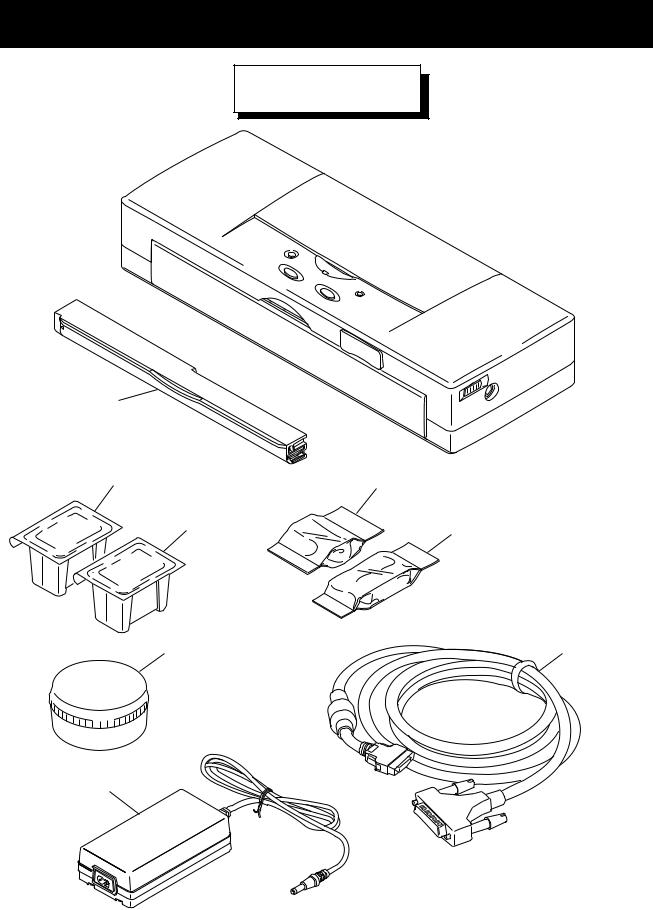
PRINTER SET
FIGURE 1
6
1 4
1 |
5 |
|
2 |
7 |
3
See FIGURE 7
B-1
|
|
FIGURE |
|
|
|
|
|
R |
|
|
Q |
|
|
|
|
|
|
|
|
|
||||||
|
|
|
|
|
|
|
A |
|
|
|
|
|
|
|
|
|
|
|
||||||||
& |
|
|
|
PART NUMBER |
|
|
|
|
T |
|
|
DESCRIPTION |
|
|
REMARKS |
|||||||||||
|
|
|
|
|
N |
|
|
|
|
|
|
|||||||||||||||
|
|
KEY NO. |
|
|
|
|
|
|
|
Y |
|
|
|
|
|
|
|
|
|
|||||||
|
|
|
|
|
|
|
K |
|
|
|
|
|
|
|
|
|
|
|
||||||||
|
|
|
|
|
|
|
|
|
|
|
|
|
|
|
|
|
|
|
|
|
|
|
|
|
||
|
|
|
|
|
|
|
|
|
|
|
|
|
|
|
|
|
|
|
|
|
|
|
|
|
||
|
|
|
|
|
|
|
|
|
|
|
|
|
|
|
|
|
|
|
|
|
|
|
|
|
||
|
1 - |
|
1 |
|
|
|
NPN |
|
|
|
|
|
|
|
1 |
|
|
BLACK BJ CARTRIDGE PACK |
|
|
|
CONSUMABLES |
|
|||
|
|
|
|
|
|
|
|
|
|
|
|
|
|
|
|
|
|
|
|
|
|
|
|
|
|
|
|
|
|
|
|
|
|
|
|
|
|
|
|
|
|
||||||||||||
|
|
|
|
|
|
|
|
NPN |
|
|
|
|
|
1 |
|
|
COLOR BJ CARTRIDGE |
PACK |
|
|
CONSUMABLES |
|||||
|
|
|
|
|
|
|
|
|
|
|
|
|
|
|
|
|
|
|
|
|
|
|
|
|
|
|
|
|
|
|
|
|
|
|
|
|
|
||||||||||||||||
|
|
2 |
|
|
|
NPN |
|
|
|
|
|
1 |
|
|
CARTRIDGE |
CONTAINER |
|
|
|
|
OPTION |
|||||
|
|
|
|
|
|
|
|
|
|
|
|
|
|
|
|
|
|
|
|
|
|
|
|
|
|
|
|
|
|
|
N |
|
|
|
|||||||||||||||||||
|
|
3 |
|
|
|
QH3-3349-000 |
|
|
|
1 |
|
|
AC ADAPTOR: 100V~240V |
50/60HZ |
|
|
OUTPUT 13VDC, 1.8A |
|||||||||
|
|
|
|
|
|
|
|
|
|
|
|
|
|
|
|
|
|
|
|
|
|
|
|
|
|
|
|
|
|
|
|
|
|
|
|
|
|
||||||||||||||||
|
|
4 |
|
|
|
NPN |
|
|
|
|
|
1 |
|
|
COLOR INK |
CARTRIDGE |
|
|
|
|
FOR COLOR BJ CARTRIDGE |
|||||
|
|
|
|
|
|
|
|
|
|
|
|
|
|
|
|
|
|
|
|
|
|
|
|
|
|
|
|
|
|
|
|
|
|
|
|
|
|
|
|
|
|
|
|
|
|
|
|
|
|
|
|
|
|
|
|
|
|
|
|
|
|
|
|
|
|
|
|
|
|
|
|
|
|
|
|
|
|
|
|
|
|
|
|
|
|
|
|
|
|
|
|
||||||||||||||||
|
|
5 |
|
|
|
NPN |
|
|
|
|
|
1 |
|
|
BLACK INK |
CARTRIDGE |
|
|
|
|
FOR COLOR BJ CARTRIDGE |
|||||
|
|
|
|
|
|
|
|
|
|
|
|
|
|
|
|
|
|
|
|
|
|
|
|
|
|
|
|
|
|
|
|
|
|
|
|
|
|
|
|
|
|||||||||||||
|
|
6 |
|
|
|
NPN |
|
|
|
|
|
1 |
|
|
LITHIUM ION |
BATTERY |
|
|
|
|
|
|
||||
|
|
|
|
|
|
|
|
|
|
|
|
|
|
|
|
|
|
|
|
|
|
|
|
|
|
|
|
|
|
|
|
|
|
|
|
|
|
|
|
|
|
||||||||||||
|
|
7 |
|
|
|
QH8-0080-000 |
|
|
|
|
|
1 |
|
|
I/F CABLE |
|
|
|
|
|
|
|
||||
|
|
|
|
|
|
|
|
|
|
|
|
|
|
|
|
|
|
|
|
|
|
|
|
|
|
|
|
|
|
|
|
|
|
|
|
|
|
|
|
|
|
|
|
|
|
|
|
|
|
|
|
|
|
|
|
|
|
|
|
|
|
|
|
|
|
|
|
|
|
|
|
|
|
|
|
|
|
|
|
|
|
|
|
|
|
|
|
|
|
|
|
|
|
|
|
|
|
|
|
|
|
|
|
|
|
|
|
|
|
|
|
|
|
|
|
|
|
|
|
|
|
|
|
|
|
|
|
|
|
|
|
|
|
|
|
|
|
|
|
|
|
|
|
|
|
|
|
|
|
|
|
|
|
|
|
|
|
|
|
|
|
|
|
|
|
|
|
|
|
|
|
|
|
|
|
|
|
|
|
|
|
|
|
|
|
|
|
|
|
|
|
|
|
|
|
|
|
|
|
|
|
|
|
|
|
|
|
|
|
|
|
|
|
|
|
B-2
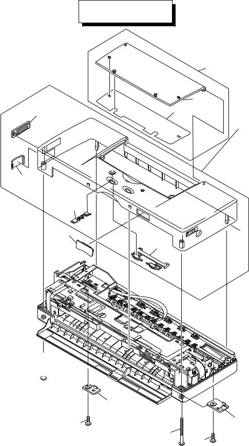
UPPER CASE
FIGURE 2
1
2
6 |
3 |
4
When removing the upper case unit, remove the lock switch cover.
7
|
|
8 |
When removing and |
|
|
reinstalling the upper |
10 |
|
case unit, remove and |
5 |
|
reinstall, respectively, the |
|
9 |
|
|
|
2 claws on the paper |
|
|
feeder side first. |
|
|
S1 
|
12 |
|
S2 |
|
11 |
S1 |
|
|
|
S2 |
|
|
|
B-3
Loading...