


REVISION 0
OCT. 1999 QY8-1368-000
COPYRIGHT ã 1999 CANON INC. CANON BJC-6500 1099 SE 0.30-0 PRINTED IN JAPAN (IMPRIME AU JAPON)
1099 SE 0.30-0

Target Readers
This manual is published by Canon Inc. for qualified persons and contains the necessary technical information for technical theory, installation, maintenance, and repair of products. This manual covers all localities where the products are sold. For this reason, it may contain information that does not apply to your locality.
Revisions
This manual may include technical inaccuracies or typographical errors due to improvements or changes in the products. When amendments are made to the content of this manual, Canon will issue technical information as the need arises. In the event of major alterations to the content of this manual over a long or short period, Canon will publish a revised version of the manual.
The following paragraphs do not apply to any countries where such provisions are
inconsistent with local law.
Trademarks
The product names and company names appearing in this manual are the registered trademarks or trademarks of the individual companies.
Copyright
This manual is copyrighted and all rights reserved. Under the copyright laws, this manual may not be copied, reproduced, or translated into other languages, in whole or in part, without the express written consent of Canon Inc. except in the case of internal business use.
Copyright ã 1999 by Canon Inc.
CANON INC.
BJ Products Quality Support Dept.
16-1, Shimonoge 3-chome, Takatsu-ku, Kawasaki-shi, Kanagawa 213, Japan
This manual was produced on an Apple Macintoshä Power Mac 9600/233 personal computer and Apple LaserWriterä II NTX-J laser beam printer; final pages were printed on Varityperä 5300 with 4000-J RIP. A Canon mo-5001S Magneto-Optical Storage Subsystem with mo-502M Magneto-Optical Storage Disk Cartridge and mo-IF2 interface kit were used for storing large volumes of page layout and graphic data for this manual.
All graphics were produced with MACROMEDIA FREEHANDä 7.0J.
All documents and all page layouts were created with QuarkXPressä 3.3J.
I. ABOUT THIS MANUAL
This manual is divided into five parts containing the information required for servicing the BJC-6500 printer.
Part 1: PRODUCT SPECIFICATIONS
This part outlines the product and its specifications.
Part 2: MAINTENANCE
This part explains maintenance of the unit. It includes precautions and details for disassembly and assembly, and adjustments required when assembling.
Part 3: OPERATION
This part explains how to operate the unit properly, and how to use the service mode.
PRODUCT |
SPECIFICATIONS |
MAINTENANCE |
|
OPERATION |
|
Part 4: TROUBLESHOOTING
This part explains how to resolve problems of the unit, and contains information on how to locate and replace serviceable units and parts. It is divided into two sections: "Troubleshooting by Errors" and "Troubleshooting by Symptoms."
Part 5: REFERENCE
This part outlines the unit operation giving technical information on hardware, and contains block diagrams, pin assignments, and wiring/circuit diagrams.
This manual does not contain complete information required for
REF. disassembling and assembling the BJC-6500 printer. Please also refer to the separate Parts Catalog.
TROUBLE |
SHOOTING |
REFERENCE |
|
I

II. TABLE OF CONTENTS
Page |
Part 1: PRODUCT SPECIFICATIONS |
|||||
1 |
- 1 |
1. |
PRODUCT OUTLINE |
|||
1 |
- |
1 |
|
1.1 |
Product Outline |
|
1 |
- 2 |
|
1.2 |
Features |
||
1 |
- 3 |
2. |
SPECIFICATIONS |
|||
1 |
- |
3 |
|
2.1 |
General Specifications |
|
1 |
- |
3 |
|
|
2.1.1 |
Printer specifications |
1 |
- |
4 |
|
|
2.1.2 |
Product life |
1 |
- |
4 |
|
2.2 |
Paper Specifications |
|
1 |
- |
4 |
|
|
2.2.1 |
Paper sizes |
1 |
- |
4 |
|
|
2.2.2 |
Paper type/settings |
1 |
- |
4 |
|
|
2.2.3 |
Printable area |
1 |
- |
5 |
|
2.3 |
BJ Cartridge Specifications |
|
1 |
- |
6 |
|
2.4 |
Scanner Cartridge Specifications |
|
1 |
|
6 |
|
|
2.4.1 |
Scannable area |
1 |
- |
7 |
|
2.5 |
Interface Specifiocations |
|
1 |
|
7 |
|
|
2.5.1 |
Parallel interface |
1 |
|
7 |
|
|
2.5.2 |
Serial interface |
1 |
- |
8 |
|
2.6 |
Printer Driver/Scanner Driver Types |
|
1 |
- 9 |
3. |
PRINTER PACKING |
|||
1 |
-10 |
4. |
NAMES OF PARTS AND THEIR FUNCTIONS |
|||
1 |
11 |
5. |
PRODUCT CODE LIST |
|||
Part 2: MAINTENANCE
2 - 1 |
1. PERIODICAL REPLACEMENT/MAINTENANCE |
|||
2 - |
1 |
1.1 |
Parts for Periodical Replacement |
|
2 - |
1 |
1.2 |
List of Periodical Maintenance |
|
2 - 2 |
2. DISASSEMBLY AND REASSEMBLY |
|||
2 - |
2 |
2.1 |
List of Tools |
|
2 - 3 |
2.2 |
Precautions for Disassembly and Reassembly |
||
2 - |
3 |
|
2.2.1 Precautions for ink stains (ink paths/ink mist) |
|
2 - |
4 |
|
2.2.2 Precautions for damage due to static electricity |
|
2 - |
5 |
|
2.2.3 Precautions for transporting the printer |
|
2 - |
5 |
|
2.2.4 Precautions on spur tip deformation |
|
2 - 6 |
2.3 |
Disassembling and Reassembling the Printer |
||
2 - |
6 |
|
2.3.1 |
Unlocking the carriage |
2 - |
6 |
|
2.3.2 |
Reinstalling tap screws |
2 - |
7 |
|
2.3.3 Removing the printer unit |
|
2 - 8 |
|
2.3.4 |
Removing the ASF unit |
|
2 - |
8 |
|
2.3.5 Removing the adjustable bushings supporting the carriage shaft |
|
2 - 9 |
|
2.3.6 Paper feed gear handling |
||
2 - |
9 |
|
2.3.7 Spur holder assembly installation |
|
2 -10 |
|
2.3.8 |
Grease application points |
|
2 -11 |
2.4 |
Adjustment/Setting Procedures |
||
2 -11 |
|
2.4.1 Adjustments (item, adjustment points, tools) |
||
2 -12 |
|
2.4.2 When to perform print head position adjustment |
||
2 -13 |
|
2.4.3 |
When to reset the EEPROM |
|
2 -13 |
|
2.4.4 How and when to adjust the carriage belt tension |
||
2 -14 |
|
2.4.5 How to adjust the ASF gear position |
||
2 -16 |
|
2.4.6 |
How to adjust the head gap |
|
2 -18 |
3. CONFIRMATION OF OPERATION |
|||
2 -18 |
3.1 |
Confirmation Methods |
||
II
2 -19 |
4. TRANSPORTING THE PRINTER |
2 -19 |
4.1 Procedures for Packing the Printer for Transportation |
Page |
Part 3: OPERATION |
||
3 - 1 |
1. FUNCTIONS RELATED TO PRINTER OPERATION |
||
3 - |
1 |
1.1 |
Status Display |
3 - |
2 |
|
1.1.1 Status display via the indicator |
3 - |
4 |
|
1.1.2 Status display via the BJ status monitor |
3 - 5 |
1.2 |
Operations from the Computer |
|
3 - |
5 |
|
1.2.1 Function settings using the printer driver |
3 - |
6 |
1.3 |
Operations from the Printer |
3 - |
6 |
|
1.3.1 Cleaning |
3 - |
6 |
|
1.3.2 Nozzle check pattern printing |
3 - 8 |
2. SERVICE FUNCTIONS |
||
3 - 8 |
2.1 |
Service Mode Operations |
|
3 - |
9 |
2.2 |
Printing the Service/Factory Test Print |
3 -10 |
2.3 |
Printing the EEPROM Information |
|
3 -11 |
2.4 |
Resetting the EEPROM |
|
3 -11 |
2.5 |
Setting the Model |
|
3 -11 |
2.6 |
Checking the Presence of Ink |
|
3 -11 |
2.7 |
Conducting the Print Head Position Adjustment |
|
3 -11 |
2.8 |
Powering Off and Locking the Carriage |
|
Part 4: TROUBLESHOOTING
4 - 1 |
1. |
TROUBLESHOOTING BY DISPLAYED ERRORS |
||
4 - |
1 |
|
1.1 |
Initial Flowchart |
4 - |
5 |
|
1.2 |
Error Indications (Indicator, Beeper, Error Code) |
4 - |
6 |
|
1.3 |
Troubleshooting by Errors |
4 -19 |
2. |
TROUBLESHOOTING BY SYMPTOMS |
||
4 -19 |
|
2.1 |
Troubleshooting by Symptoms |
|
III
Page |
Part 5: REFERENCE |
|
5 - 1 |
1. TECHNICAL REFERENCE |
|
5 - 1 |
1.1 |
Functions of the Paper Feed Unit |
5 - 2 |
1.2 |
Construction of the Paper Feed Unit |
5 - 3 |
1.3 |
Form Alignment Function |
5 - 4 |
1.4 |
Transmission Gear Unit |
5 - 5 |
1.5 |
Detection with Sensors |
5 - 5 |
1.6 |
BJ Cartridge Indenrification |
5 - 6 |
2. CONNECTOR POSITIONS AND PIN ASSIGNMENT |
|
5 - 6 |
2.1 |
Control Board |
5 -11 |
2.2 |
Carriage Board |
5 -14 |
2.3 |
BJ Cartridge |
5 -15 |
2.4 |
Scanner Cartridge (Optional) |
5 -16 |
2.5 |
AC Adapter |
5 -16 |
2.6 |
DC Power Supply Cable |
5 -17 |
2.7 |
Carriage Motor |
5 -17 |
2.8 |
Paper Feed Motor |
5 -17 |
2.9 |
Paper End Sensor |
5 -18 |
2.10 Ink Sensor |
|
5 -18 |
2.11 Print Position Sensor |
|
5 -18 |
2.12 Pump Sensor |
|
5 -19 |
3. INSTALLATION |
|
5 -19 |
3.1 |
Installation |
5 -19 |
|
3.1.1 Installation location |
5 -19 |
3.2 |
Installation Procedures |
5 -19 |
|
3.2.1 Connecting the interface cable |
5 -19 |
|
3.2.2 Connecting the power supply |
5 -20 |
4. MISCELLANEOUS |
|
5 -20 |
4.1 |
Similarities and Differences to the BJC-6100 |
IV

III. ILLUSTRATION INDEX
Page |
Part 1: PRODUCT SPECIFICATIONS |
||
1 - 1 |
Figure 1- |
1 |
Printer Appearance |
1 - 5 |
Figure 1- |
2 |
Printable Area |
1 - 6 |
Figure 1- |
3 |
Scannable Area |
1 - 9 |
Figure 1- |
4 |
Packaging |
1 -10 |
Figure 1- |
5 |
Names of Parts and Their Functions |
Part 2: MAINTENANCE
2 - 3 |
Figure |
2- |
1 |
Ink Paths |
2 - 4 |
Figure |
2- |
2 |
Ink Mist |
2 - 5 |
Figure |
2- |
3 |
Capping Position |
2 - 5 |
Figure |
2- |
4 |
Spur Unit |
2 - 6 |
Figure |
2- |
5 |
Unlocking the Carriage |
2 - 7 |
Figure |
2- |
6 |
Removing the Printer Unit |
2 - 8 |
Figure 2- |
7 |
Removing the ASF Unit |
|
2 - 8 |
Figure |
2- |
8 |
Adjustable Bushings Supporting the Carriage Shaft |
2 - 9 |
Figure 2- |
9 |
Paper Feed Gears |
|
2 - 9 |
Figure |
2- 10 |
Spur Holder Ass'y Installation |
|
2 -10 |
Figure 2- 11 |
Grease Points |
||
2 -12 |
Figure |
2- 12 |
Print Position Adjustment Pattern |
|
2 -13 |
Figure 2- 13 |
Carriage Belt Tension Adjustment |
||
2 -14 |
Figure 2- 14 |
ASF Gear Position Adjustment 1 |
||
2 -15 |
Figure 2- 15 |
ASF Gear Position Adjustment 2 |
||
2 -16 |
Figure 2- 16 |
Head Gap Adjustment 1 |
||
2 -17 |
Figure 2- 17 |
Head Gap Adjustment 2 |
||
Part 3: OPERATIONS
3 - 1 |
Figure 3- |
1 |
Operation Panel |
||
3 - 4 |
Figure 3- |
2 |
BJ Status Monitor (Sample) |
||
3 - |
5 |
Figure |
3- |
3 |
Printer Driver Utility (Sample) |
3 - |
7 |
Figure |
3- |
4 |
Nozzle Check Pattern Print (Sample for Black/Color Cartridge) |
3 - |
9 |
Figure |
3- |
5 |
Service/Factory Test Print |
3 -10 |
Figure 3- |
6 |
EEPROM Information Print (Sample) |
||
3 -11 |
Figure 3- |
7 |
Checking for Presence of Ink |
||
V
Part 5: REFERENCE
5 - 1 |
Figure 5- |
1 |
Paper Feed Path |
||
5 - 2 |
Figure 5- |
2 |
Paper Pick-up Unit |
||
5 - 3 |
Figure 5- |
3 |
Form Alignment Function |
||
5 - 3 |
Figure 5- |
4 |
Form Alignment Function On/Off |
||
5 - |
4 |
Figure |
5- |
5 |
Drive Switching Unit |
5 - |
4 |
Figure |
5- |
6 |
Operation of the Drive Switching Unit |
5 - |
5 |
Figure |
5- |
7 |
Sensor Positions |
5 - 6 |
Figure 5- |
8 |
Control Board |
||
5 - 6 |
Figure 5- |
9 |
Block Diagram |
||
5 -11 |
Figure 5- 10 |
Carriage Board |
|||
5 -14 |
Figure 5- 11 |
BJ Cartridge |
|||
5 -15 |
Figure 5- 12 |
Scanner Cartridge |
|||
5 -16 |
Figure 5- 13 |
AC Adapter |
|||
5 -16 |
Figure 5- 14 |
DC power Supply Cable |
|||
5 -17 |
Figure 5- 15 |
Carriage Motor |
|||
5 -17 |
Figure 5- 16 |
Paper Feed Motor |
|||
5 -17 |
Figure 5- 17 |
Paper End Sensor |
|||
5 -18 |
Figure 5- 18 |
Ink Sensor |
|||
5 -18 |
Figure |
5- 19 |
Print Position Sensor |
||
5 -18 |
Figure 5- 20 |
Pump Sensor |
|||
5 -19 |
Figure 5- 21 |
Printer Dimensions |
|||
VI
IV. TABLE INDEX
Page |
Part 3: OPERATION |
||
3 - 2 |
TABLE 3- |
1 |
STATUS DISPLAY VIA THE INDICATOR |
|
Part 4: |
TROUBLESHOOTING |
|
4 - 5 |
TABLE 4- |
1 |
ERROR INDICATIONS |
VII

Part 1
PRODUCT SPECIFICATIONS
Page |
|
|
|
|
1 - 1 |
1. |
PRODUCT OUTLINE |
||
1 - |
1 |
|
1.1 |
Product Outline |
1 - 2 |
|
1.2 |
Features |
|
1 - 3 |
2. |
SPECIFICATIONS |
||
1 - |
3 |
|
2.1 |
General Specifications |
1 - |
4 |
|
2.2 |
Paper Specifications |
1 - |
4 |
|
2.3 |
BJ Cartridge Specifications |
1 |
6 |
|
2.4 |
Scanner Cartridge |
1 - |
7 |
|
2.5 |
Interface Specifications |
1 - |
8 |
|
2.6 |
Printer Driver Types |
1 - 9 |
3. |
PRINTER PACKING |
||
1 -10 |
4. |
NAMES OF PARTS AND THEIR FUNCTIONS |
||
1 11 |
5. |
PRODUCT CODE LIST |
||

BJC-6500 |
Part 1: PRODUCT SPECIFICATIONS |
1.PRODUCT OUTLINE
1.1Product Outline
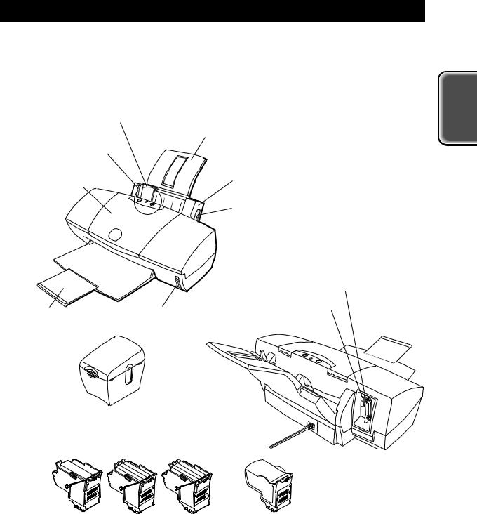
This printer is a BJC-6100 leveraged printer, attaining high performance in a businessuse setting. It supports on A3 size paper, and utilizes the BJC-6100 printer engine to achieve high-speed/high-quality printing.
Operation Panel
Paper Support
Paper Guide
Front Cover |
Auto Sheet Feeder |
|
|
|
Paper Selector Lever |
|
Parallel Interface Connector |
Paper Output Tray |
USB Interface Connector |
Paper Thickness Lever |
PRODUCT |
SPECIFICATIONS |
SB-30
Cartridge Container
BC-30 |
BC-31 BC-32 Photo |
IS-32 |
|
BJ Cartridges |
Scanner Cartridge |
Figure 1-1 Printer Appearance
1-1
Part 1: PRODUCT SPECIFICATIONS |
BJC-6500 |
1.2 Features
This printer differs from the BJC-6100 in the following ways:
1.Supported paper size has increased from A4 to A3
2.Automatic Form Alignment Function (improves skew control) n/a→built-in
For details, refer to Part 5: REFERENCE (Page 5-20).
Other functions remain commonly shared with the BJC-6100, as follows.
•Laser-printer quality using pigment black ink
•Dual-cartridge system
High quality printing at high speed from a combination of the Black and Color cartridges or the Color and Photo cartridges
Black BJ cartridge: Drop modulation, replaceable ink tank (pigment black), 160 nozzle head
Color BJ cartridge: Drop modulation, individually replaceable ink tanks (yellow, magenta and cyan), 144 in-line nozzle head (48 nozzles for each of three colors)
Photo BJ cartridge: Drop modulation, individually replaceable ink tanks (dye black, photo-magenta and photo-cyan), 144 in-line nozzle head (48 nozzles for each of three colors)
•Individually replaceable ink tanks for high cost performance Black ink tanks: Pigment black ink tank
Color ink tanks: Yellow, magenta, and cyan ink tanks Photo ink tanks: Dye black, magenta, and cyan ink tanks
Ink-out detection, and translucent ink tanks for easier ink level checking
•High speed printing (9.0 PPM black printing or 6.0 PPM color printing in HS mode) 1440 x 720 dpi high resolution printing
•Automatic printing position adjustment
Ensures accurate printing position regardless of cartridges being used or carriage movement direction
•Supports a wide variety of print media
•Blue Angel compliant
•USB and IEEE 1284 compatible 8-bit parallel interfaces.
•Optional scanner cartridge with maximum readout resolution of 720×720 dpi also available.
1-2

BJC-6500 |
Part 1: PRODUCT SPECIFICATIONS |
2.SPECIFICATIONS
2.1General Specifications
2.1.1Printer specifications
Type |
|
Desktop serial color bubble-jet printer |
|
|
||||
Paper feeding method |
|
Automatic sheet feeder (no manual feed) |
|
|||||
Resolution |
|
1440dpi x 720dpi |
(maximum resolution) |
|
||||
Throughput |
|
|
|
|
HS |
|
HQ |
Fine |
|
|
BC-30 + BC-31 |
|
|
|
|
|
|
|
|
Black Text (PC Magazine) |
8.0ppm |
6.5ppm |
... |
|||
|
|
Black (New Black) |
|
9ppm |
7.1ppm ... |
|||
|
|
Color (New Color) |
|
6ppm |
4.6ppm |
... |
||
|
|
BC-32Photo + BC-31 |
|
|
|
|
||
|
|
Photo |
|
|
... |
|
... |
0.17ppm |
Printing direction |
|
HS mode: |
|
|
|
Bi-directional |
||
|
|
HQ mode: (360dpi x 360dpi): |
Bi-directional |
|||||
|
|
Fine mode (720dpi x 720dpi): |
Uni-directional |
|||||
|
|
Fine mode (1440dpi x 720dpi): |
Uni-directional |
|||||
|
|
|
|
|
|
|
|
|
Printing width |
|
289.6mm |
|
|
|
|
|
|
Line feed speed |
|
HQ, HS mode |
4 "/S |
|
|
|
|
|
Interface |
|
IEEE 1284-compatible 8-bit parallel interface |
|
|||||
|
|
(Compatible/nibble/ECP), USB |
|
|
|
|||
Automatic sheet feeder capacity |
|
|
|
|
|
|
||
Plain paper: |
10 mm max. stacking height (about 100 sheets of 64 g/m2 paper) |
|||||||
High-resolution paper: 10 mm max. stacking height (about 80 sheets of High- |
||||||||
|
resolution paper) |
|
|
|
|
|
||
Detection functions |
|
|
|
|
|
|
|
|
Cover open: |
|
Yes |
Paper detection: |
|
Yes |
|
||
BJ cartridge installed: |
|
Yes |
Ink-out : |
|
|
Yes |
|
|
Print position detection: |
Yes |
Waste ink amount: |
|
Yes |
|
|||
BJ cartridge identification: |
Yes |
Paper width detection: |
|
No |
|
|||
Pick-up roller position: |
|
Yes |
|
|
|
|
|
|
Acoustic noise during operation |
|
|
|
|
|
|
||
Approx. 48 dB / HQ mode |
(Sound pressure level: compliant with ISO9296) |
|||||||
Environmental conditions |
|
|
|
|
|
|
|
|
Operating: |
|
5 to 35°C (41 to 95° F), 10 to 90% RH (no condensation) |
||||||
Storage: |
|
0 to 35°C (32 to 95° F), 5 to 95% RH (no condensation) |
||||||
Power consumption |
|
Operating |
|
|
Standby |
|
|
|
|
|
Approx. 30 W max. |
Approx. 3 W max. |
|
||||
External dimensions |
|
574 mm W x 328mm D x 205 mm H |
|
|
||||
Weight |
|
6.8 kg, including BJ cartridges |
|
|
|
|||
|
|
|
|
|
|
|
|
|
Certification |
|
|
|
|
|
|
|
|
Electromagnetic radiance: |
VDE0871 CLASS B, CISPR PUBLICATION '22 |
|
||||||
Electrical safety: |
|
Energy Star, IEC950, AS, GS, FIMCO, SEMCO, SISIR, |
||||||
|
|
Electrical Safety Regulations of Korea, CCIB (China), |
||||||
|
|
CE Mark, EI, MEMCO |
|
|
|
|
||
Environmental regulations: |
Energy Star, Blue Angel |
|
|
|
|
|||
|
|
|
||||||
Serial No. location |
|
On the printer frame (visible when the front cover is open) |
||||||
|
|
|
|
|
|
|
|
|
PRODUCT |
SPECIFICATIONS |
1-3

Part 1: PRODUCT SPECIFICATIONS |
BJC-6500 |
2.1.2 Product life
The print quality can be assured during the product life given below, if the specified
maintenance is conducted. |
|
|
(1) |
Monochrome printing |
60,000 sheets (1500 ANK character pattern) OR, |
(2) |
Color printing |
12,000 sheets (7.5% duty per color pattern) OR, |
(3)5 years (from the start of use), whichever comes first
2.2Paper Specifications
2.2.1 Paper sizes
(1) Paper size
A5, A4, A3 (V), B5, B4 (V), Letter, Legal, A4+, Letter+, Envelope Com #10/DL, Other (100 x 100 ~ 297 x 584mm)
(2) Paper weight
Automatic Sheet Feeder: 64 ~ 105 g/m2
2.2.2 Paper type/settings
Paper Type |
|
Stacked in the ASF |
Paper selector |
Paper thickness |
|
|
|
lever position |
lever position |
|
|
|
|
|
Plain paper (64 g/m2) |
|
Approx. 10mm or less |
Back |
Up |
|
|
(Approx. 100 sheets) |
|
|
Color BJ paper |
LC-301 |
Approx. 10mm or less |
Back |
Up |
High-resolution |
HR-101 |
Approx. 10mm or less |
Back |
Up |
paper |
|
(Approx. 80 sheets) |
|
|
Glossy photo paper |
GP-301 |
1 sheet (portrait) |
Forward |
Up |
Glossy photo film |
HG-201 |
1 sheet |
Forward |
Up |
OHP film |
CF-102 |
30 sheets or less |
Back |
Up |
Back print film |
BF-102 |
10 sheets or less |
Back |
Up |
BJ cloth |
FS-101 |
1 sheet |
Forward |
Down |
Banner paper |
BP-101 |
1 sheet |
Forward |
Down |
T-shirt transfer |
TR-201 |
1 sheet |
Forward |
Down |
Glossy photo card |
FM-101 |
1 sheet |
Forward |
Up |
Envelope |
Com. #10 |
10 sheets or less |
Forward |
Down |
|
DL |
(portrait) |
|
|
Thick paper |
|
1 sheet |
Forward |
Down |
|
|
|
|
|
If the Paper Selector Lever/Paper Thickness Lever are incorrectly set for the CAUTION paper used, paper feeding or printing problems may occur. For details on the
lever positions, refer to Part 1: PRODUCT SPECIFICATIONS (Page 1-10).
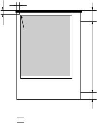
2.2.3 Printable area
Refer to Figure 1-2 Printable Area.
1-4

BJC-6500 |
Part 1: PRODUCT SPECIFICATIONS |
2.3 BJ Cartridge Specifications
|
|
|
|
|
Black BJ cartridge |
|
Color BJ cartridge |
Photo BJ cartridge |
||||||||||
Construction: |
|
Separate ink tank |
|
Separate ink tank |
Separate ink tank |
|||||||||||||
Print head: |
|
160 nozzles, in-line |
144 nozzles, in-line |
144 nozzles in-line |
||||||||||||||
|
|
|
|
|
|
|
|
|
|
(48 nozzles x 3) |
(48 nozzles x 3) |
|||||||
Inks: |
|
|
|
|
Pigment black |
|
C, M, Y |
|
|
|
|
Photo-Bk, Photo-C, Photo-M |
||||||
Cartridge life: |
|
Approx. 5000 pages* |
Approx. 3000 pages** |
Approx. 3000 pages** |
||||||||||||||
Ink tank: |
|
|
|
|
Black |
|
C, M, Y |
|
|
|
|
Photo-Bk, Photo-C, Photo-M |
||||||
Ink tank life: |
|
Approx. 500 pages* |
Approx. 280 pages** |
Approx. 280 pages** |
||||||||||||||
Cartridge weight: |
Approx. 60 g |
|
Approx. 60 g |
Approx. 60 g |
||||||||||||||
(w/o ink tank) |
|
|
|
|
|
|
|
|
|
|
|
|
|
|
|
|||
|
|
|
|
|
|
|
|
|
|
|
|
|
|
|
|
|
|
|
* |
Monochrome printing |
(1500-character, HQ mode) |
||||||||||||||||
** |
Color printing |
(7.5% duty, HQ mode) |
|
|
|
|
||||||||||||
|
|
A3, A4, A5 and B5 sizes |
|
|
Letter (LTR) and legal (LGL) |
|||||||||||||
|
|
|
|
|
|
|
|
(1) 18.5mm |
|
|
|
|
|
|
|
(1) 18.5mm |
||
|
|
|
|
|
|
|
|
|
|
|
|
|
|
|
|
|||
|
3mm |
|
|
|
|
|
3mm |
|
|
|
||||||||
|
|
|
|
|
|
|
|
|
(2) 26.5mm |
|
|
|
|
|
|
|
(2) 26.5mm |
|
|
|
|
|
|
|
|
|
|
|
|
|
|
|
|
|
|
|
|
|
(2) 27.0mm |
|
|
5.0mm |
(1) 22.5mm |
|
|
3.4mm |
3.4mm |
(2) 27.0mm |
|
(1) 22.5mm |
|||
|
5.0mm |
||
|
6.4mm |
6.4mm |
PRODUCT |
SPECIFICATIONS |
A4+ and letter+ (LTR+) sizes
27.94mm
27.94mm
5.08mm |
A4+ 5.88mm |
|
***+ 5.08mm |
29.21mm
sizes
Envelope |
|
3.0mm |
|
29.21mm |
|
5.0mm |
|
6.4mm |
6.4mm |
|
: Recommended printing area |
(1) |
Monochrome printing |
|
: Printable area |
(2) |
Color or photo printing |
|
|||
|
|
|
|
Figure 1-2 Printable Area
1-5
Part 1: PRODUCT SPECIFICATIONS |
BJC-6500 |
||
2.4 Scanner Cartridge Specifications |
|||
|
|
|
|
|
Name |
IS-32 |
|
|
Type |
Cartridge replacement type color scanner |
|
|
|
|
|
|
Resolution (dpi) |
90×90, 180×180, 300×360, 360×360, 720×720 |
|
|
Image sensor |
Single-line, 256 pixel CCD |
|
|
|
|
|
|
Light source |
RGB (R; Red, G; Green, B; Blue) |
|
|
|
|
|
|
Scanning method/direction |
Sequential RGB light source switching method |
|
|
|
|
|
|
Document feeding method |
Place the document into the scanning holder and feed it |
|
|
|
through ASF |
|
|
|
|
|
|
Gradation |
10 bit input, 8 bit output |
|
|
|
|
|
|
Input voltage |
5/12 V |
|
|
|
|
|
|
Power consumption |
Approx 30 W (90 dpi, monochrome), SW (stand by) |
|
|
|
|
|
|
Interface |
ECP/Nibble |
|
|
|
|
|
|
External dimensions |
Approx. 41 mm W × 90 mm D × 77 mm H |
|
|
Weight |
Approx. 100 g |
|
|
|
|
|
|
Others |
Raise the paper selector lever on the printer upward |
|
|
|
when scanning |
|
|
|
|
|
|
|
Scannable paper thickness: 0.25 mm or less |
|
|
|
|
|
2.4.1 Scannable area
Place the image to scan in the scanning holder with the upper left corner fitted to the placement point.
Holder Type |
Paper |
Size (width x height) |
Scannable area (width x height) |
|
|
|
|
SH-101 |
A6 |
105 x 148 mm |
98.2 x 138 mm |
(220 x 327 mm) |
A5 |
148 x 210 mm |
141.2 x 200 mm |
|
A4 |
210 x 297 mm |
203.2 x 287 mm |
|
B5 |
182 x 257 mm |
175.2 x 247 mm |
|
Letter |
8.5 x 11 inch |
208.2 x 269.4 mm |
SH-102 |
A3 |
297 x 420 mm |
289 x 410 mm |
(300 x 458 mm) |
Ledger |
11 x 17 inch |
272.6 x 421.8 mm |
|
Legal |
8.5 x 14 inch |
208.2 x 332.6 mm |
|
B4 |
257 x 364 mm |
250.2 x 354 mm |
|
|
|
|
|
3.4mm |
6mm |
32mm |
|
|
|
Placement point |
|
Recommended scanning area |
|
23mm |
Scanning holder

 : Scannable Area
Figure 1-3 Scannable Area
1-6
BJC-6500 |
Part 1: PRODUCT SPECIFICATIONS |
2.5Interface Specifications
2.5.1Parallel interface
1) Interface type
IEEE 1284 compatible parallel interface
2) Data transfer
8-bit parallel interface (supports nibble/ECP modes)
3) Signal voltage levels
Input: |
|
"Low" level: |
0.0V to +0.8V |
"High" level: |
+2.4V to +5.0V |
PRODUCT |
SPECIFICATIONS |
Output: |
|
|
"Low" level: |
0.0V to +0.8V |
|
"High" level: |
+2.4V to +5.25V |
|
4) |
Input/output |
|
Each signal pulled up with +5V |
||
5) |
Interface cable |
|
Twisted-pair double shielded cable, shorter than 2.0m |
||
IEEE 1284 compatible required |
||
Material: |
AWG No. 28 or higher (AWG: American Wire Gauge) |
|
6) |
Interface connector |
|
Printer-side |
Amphenol 57-40360 (or equivalent) |
|
Cable-side |
Amphenol 57-30360 (or equivalent) |
|
7) |
Input/output signal and pin arrangements |
|
Refer to Part 5: 2. CONNECTOR POSITIONS AND PIN ASSIGNMENT (Page 5-6) for details.
2.5.2 Serial interface
1) Interface type
USB Interface (Universal Serial Bus; USB Specification Release Number 1.10)
2) Data transfer
Control transfer method Bulk transfer method
3) Signal voltage level
Input:
Input difference sensitivity: +0.2V (Max) Common-mode difference: +0.8V to +2.5V
Output: |
|
Static output high: |
+2.8V to 3.6V |
Static output low: |
less than +0.3V |
4) Input/output
Each signal pulled up with 3.3V
5) Interface cable
Twisted-pair shielded cable
USB standard compatible required
Material AWG No.28, Data pair (AWG: American Wire Gauge) AWG No.20 to No.28, Power distribution pair
6) Interface connector
Printer-side |
USB standard, Series B receptacle |
Cable-side |
USB standard, Series B plug |
7) Input/output signal and pin arrangements
Refer to Part 5: 2. CONNECTOR POSITIONS AND PIN ASSIGNMENT (Page 5-6) for details.
1-7
Part 1: PRODUCT SPECIFICATIONS |
BJC-6500 |
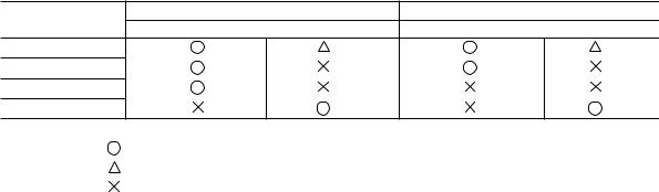
2.6 Printer Driver / Scanner Driver Types
For support of dual interfaces (USB and Centronics) and scanner, 6 drivers are
prepared.
Windows:
Macintosh:
Available combinations of interface and driver under each OS are given in the table below.
|
For use of the printer (BJ Raster driver) |
For use of the scanner (Scanner driver) |
|
OS |
Parallel interface |
USB interface |
Parallel interface*3 USB interface |
Windows 95 / 98 |
|
*2 |
*2 |
Windows NT 4.0 |
|
|
|
Windows 2000 |
|
|
|
Macintosh |
|
|
|
|
: Usable. |
|
|
|
: Usable on condition. |
|
|
|
: Not usable |
|
|
*1: At installation of the driver, select either parallel or USB according to the cable connected.
*2: Correct operation is guaranteed only for Windows 98 pre-installed computers, though the USB interface may operate under Windows 95.
*3: The parallel interface operates in the nibble or ECP modes.
1-8

BJC-6500 |
Part 1: PRODUCT SPECIFICATIONS |
3. PRINTER PACKING
After opening the printer box, confirm that all items below are included.
Set Up Software &
Reference Guide
Quick Start Guide
Read This First
Paper Output Tray
User's Guide
Paper Support
Ink Tanks |
Packing |
|
Packing |
Printer |
Cartridge Container
BJ Cartridges
Packing
Packing |
Tape |
|
PRODUCT |
SPECIFICATIONS |
Figure 1-4 Packaging
1-9
Part 1: PRODUCT SPECIFICATIONS |
BJC-6500 |
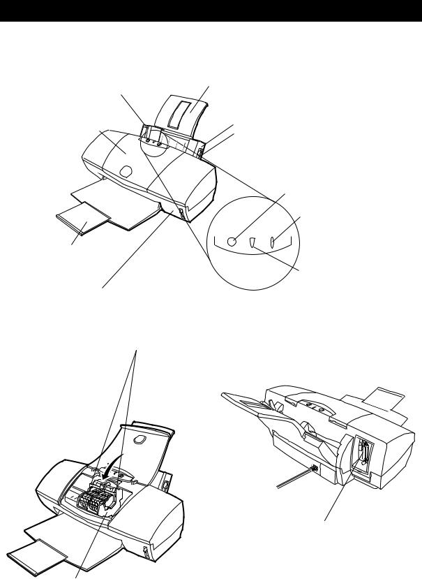
4. NAMES OF PARTS AND THEIR FUNCTIONS
The names of the printer parts, and their functions are as shown below.
Paper Guide
Lightly press this guide against the left side of paper sheets to align them.
Paper Support
Extend this paper rest to support larger sized paper.
Front Cover
Open this cover when replacing BJ cartridges or, clearing paper-jams.
Paper Output Tray
Auto Sheet Feeder
Paper Selector Lever
By moving the lever back or forward, the paper feed method ( to use or not use the ASF unit's claws ) is selected. Here the lever is in the forward position.
POWER button
Press this button to power on or off the printer.
RESUME button
After correcting a problem,  press this button to make the
printer ready.
Allows smooth ejection of paper and reduces paper friction.
Paper Thickness Selector Lever
Use this selector to adjust the gap between the print head and the paper for different paper types. Set it to the uppermost position for normal plain paper.
Operation Panel
Cartridge Lock Lever
Use this lever to secure the BJ cartridges to the carriage.
Raise it to remove the BJ cartridge.
Carriage
The left side of the carriage holds the Black or Photo BJ cartridge, and the right side hold the Color BJ cartridge.
Indicator
Not lit when powered off. When lit in green, the printer is ready to print.
When lit or blinking in orange, an error has occurred, and the printer cannot print.
Interface Connectors
Connects to the interface cable from the computer.
Two types of connector interface, USB and parallel, are provided.
Figure 1-5 Names of Parts and Their Functions
1-10

BJC-6500 Part 1: PRODUCT SPECIFICATIONS
5. PRODUCT CODE LIST
The product codes for the printer, consumables, and options are shown in TABLE 1-1. |
|
|
|||
|
|
|
|
|
|
Item |
|
Name |
Product code |
|
|
Printer |
- |
BJC-6500 |
Q30-3300 |
PRODUCT |
SPECIFICATIONS |
|
|
|
Q30-3182 |
||
|
|
|
|
|
|
BJ cartridge |
Black |
BC-30 |
F45-1471 |
|
|
|
Color |
BC-31 |
F45-1491 |
|
|
|
Photo |
BC-32 Photo |
F45-1511 |
|
|
Ink tank |
Black |
BCI-3BK |
F47-2171 |
|
|
|
Cyan |
BCI-3C |
F47-2181 |
|
|
|
Magenta |
BCI-3M |
F47-2191 |
|
|
|
Yellow |
BCI-3Y |
F47-2201 |
|
|
|
Photo Black |
BCI-3PBK Photo |
F47-2231 |
|
|
|
Photo Cyan |
BCI-3PC Photo |
F47-2211 |
|
|
|
Photo Magenta |
BCI-3PM Photo |
F47-2221 |
|
|
Cartridge container |
- |
SB-30 |
Q70-4040 |
|
|
Scanner cartridge |
- |
IS-32 |
Q70-4070 |
|
|
Scanning holder for A4, LTR |
Scanning Holder |
SH-101 |
Q70-3640 |
|
|
Scanning holder for A3, LDR |
Scanning Holder |
SH-102 |
Q70-4140 |
|
|
1-11
Part 1: PRODUCT SPECIFICATIONS |
BJC-6500 |
This page intentionally left blank
1-12

Part 2
MAINTENANCE
Page |
|
|
|
|
2 - 1 |
1. |
PERIODICAL REPLACEMENT/MAINTENANCE |
||
2 - |
1 |
|
1.1 |
Parts for Periodical Replacement |
2 - |
1 |
|
1.2 |
List of Periodical Maintenance |
2 - 2 |
2. |
DISASSEMBLY AND REASSEMBLY |
||
2 - |
2 |
|
2.1 |
List of Tools |
2 - 3 |
|
2.2 |
Precautions for Disassembly and Reassembly |
|
2 - 6 |
|
2.3 |
Disassembling and Reassembling the Printer |
|
2 -11 |
|
2.4 |
Adjustment/Setting Procedures |
|
2 -18 |
3. |
CONFIRMATION OF OPERATION |
||
2 -18 |
|
3.1 |
Confirmation Methods |
|
2 -19 |
4. |
TRANSPORTING THE PRINTER |
||
2 -19 |
|
4.1 |
Procedures for Packing the Printer for Transportation |
|

BJC-6500 |
Part 2: MAINTENANCE |
1.PERIODICAL REPLACEMENT / MAINTENANCE
1.1Parts for Periodical Replacement
Level |
Parts for periodical replacement |
User |
None |
Service personnel |
None |
|
|
|
|
Level |
Consumable |
|
|
User |
Black BJ cartridge |
|
Color BJ cartridge |
|
Photo BJ cartridge |
|
Black ink tank for the Black BJ cartridge |
|
Cyan, magenta, and yellow ink tanks for the Color BJ cartridge |
|
Photo cyan, photo magenta, and photo black ink tanks for the |
|
Photo BJ cartridge |
|
Scanner cartridge (Optional) |
|
|
Service personnel |
None |
1.2 List of Periodical Maintenance |
|
|
|
Level |
Location |
|
|
User |
None |
Service personnel |
None |
|
|
MAINTENANCE
2-1

Part 2: MAINTENANCE |
BJC-6500 |
2.DISASSEMBLY AND REASSEMBLY
2.1List of Tools
Ordinary Tools |
Note |
Phillips screwdriver |
For removing and replacing screws |
Phillips screwdriver |
For removing and replacing screws for the control board |
(about 38 mm long) |
|
Blade screwdriver |
For removing plastic parts |
Long-nose pliers |
For removing and replacing springs |
Tweezers |
For removing and installing flexible cables |
Flat brush |
For applying grease (one per grease type) |
Oil applicator |
For applying FLOIL 946P |
Multimeter |
For troubleshooting |
Paperclip (diameter 1.27 mm) |
Substitute for Lock Pin QY9-0053 |
|
|
Special Tools (part no.) |
Note |
1.9-mm gap gauge |
One for head gap adjustment (see Page 2-17) |
(QY9-0038-000) |
|
0.5-mm gap gauge |
One for head gap adjustment (see Page 2-17) |
(QY9-0001-000) |
|
Tension spring |
For carriage belt tension adjustment (see Page 2-13) |
(QY9-0052-000) |
|
Lock pin |
For matching gear-phase of the ASF drive switching unit |
(QY9-0053-000) |
(see Page 2-15) |
MOLYKOTE PG-641 grease |
For application to specified locations (see Page 2-10) |
(CK-0562-000) |
|
FLOIL 946P grease |
For application to specified locations (see Page 2-10) |
(QY9-0045-000) |
|
|
|
2-2
 Loading...