


V85
Burnham V85, V86, V87, V88, V89 Installation & Service Instructions Manual
...
8
DNAGNITAREPO,NOITALLATSNI
ROFSNOITCURTSNIECIVRES
SEIRES8V
RELIOBDERIF-LIO
gnikeesnehW.reilppusliororotcartnocgnitaehruoyllac,reliobotsriaperroecivresroF
gnitaRnonwohssarebmuNlaireSdnarebmuNledoMrelioBedivorp,reliobnonoitamrofni
.reliobehtfopotnodetacollebaL
rebmuNledoMrelioB rebmuNlaireSrelioB etaDnoitallatsnI
____-____8V_ _______6
rotcartnoCgnitaeH rebmuNenohP
sserddA
As an
ENERGY
®
Partner,
STAR
Burnham Hydronics
has determined that the
V83S, V83WM, V84S,
V84WM, V85S, V85WM,
V86S, V86WM and V87
meet the ENERGY STAR
guidelines for Energy
efciency established by the
United States Environmental
Protection Agency (EPA).
®
8142824R10.5-4/07
Price - $3.00
IMPORTANT INFORMATION - READ CAREFULLY
All boilers must be installed in accordance with National, State and Local Plumbing, Heating
and Electrical Codes and the regulations of the serving utilities. These Codes and Regulations
may differ from this instruction manual. Authorities having jurisdiction should be consulted
before installations are made.
In all cases, reference should be made to the following Standards:
USA BOILERS
A. Current Edition of American National Standard ANSI/NFPA 31, “Installation of Oil
Burning Equipment”, for recommended installation practices.
B. Current Edition of American National Standard ANSI/NFPA 211, “Chimneys, Fireplaces,
Vents, and Solid Fuel Burning Appliances”, For Venting requirements.
C. Current Edition of American Society of Mechanical Engineers ASME CSD-1, “Controls and
Safety Devices for Automatically Fired Boilers”, for assembly and operations of controls
and safety devices.
D. All wiring on boilers installed in the USA shall be made in accordance with the National
Electrical Code and/or Local Regulations.
CANADIAN BOILERS
A. Current Edition of Canadian Standards Association CSA B139, “Installation Code for Oil
Burning Equipment", for recommended Installation Practices.
B. All wiring on boilers installed in Canada shall be made in accordance with the Canadian
Electrical Code and/or Local Regulations.
The following terms are used throughout this manual to bring attention to the presence of
hazards of various risk levels, or to important information concerning product life.
REGNAD
suodrazahyltnenimminasetacidnI
tluserlliw,dediovatonfi,hcihwnoitautis
i
.egamadytreporp
laitnatsbusroyrujnisuoires,htaedn
.egamad
GNINRAW
suodrazahyllaitnetopasetacidnI
dluoc,dediovatonfi,hcihwnoitautis
royrujnisuoires,htaednitluser
reporplaitnatsbus
.egamadyt
NOITUAC
ECITON
.sdrazahyrujnilanosrep
ECITON
.snoitcurtsniesehthtiwecnadroccanidetarepo
suodrazahyllaitnetopasetacidnI
tluseryam,dediovatonfi,hcihwnoitautis
ytreporproyrujnironimroetaredomni
nosnoitcurtsnilaicepssetacidnI
ecnanetniamro,noitarepo,noitallatsni
otdetalertontubtnatropmierahcihw
.launamsihtfokcabehtnodetnirpsihcihwfoypoca,ytnarrawdetimilasahreliobsihT
dnadeniatniam,dellatsnineebsahreliobehtfiylnodilavsireliobsihtrofytnarrawehT
2
rpgnirutcafunamehtotdetubirttaebyamsnoitcesnoritsacnotsurecafruS
ehttceffatonseoddnalamronsitsurecafruS.egarotsgnirudnoitasnednocsa
reliobafoytivegnolroecnamrofrep
.
llewsasseco

REGNAD
rosihtfoytinicivehtnisdiuqilrosropavelbammalfrehtoroenilosagesuroerotsTONOD
.ecnailpparehtoyna
GNINRAW
ytreporpesuacnacecnanetniamroecivres,noitaretla,tnemtsujda,noitallatsnireporpmI
illawollofoteruliaF.efilfossolroyrujnilanosrep,egamad
anosrepesuacnacredro
raendetsopdnanoitidnocelbigelnierutaretildnalaunamsihtpeeK.ecnailppa
.naicinhcetecivresdnarenwoybecnereferrofecnailppa
reporpehtnisnoitcurtsn
,snoitcurtsnilladnatsrednudnadaeR.htaedroyrujnil
dedivorperahcihwslaunamsrerutcafunamtnenopmocnideniatnocesohtllagnidulcni
sihtgnicivresrogniniatniam,gnitarepo,pu-gnitrats,gnillatsnierofebecnailppaehthtiw
efasetarepootecivresdnaecnanetniamralugerseriuqerreliobsihT
.launamsihtnideniatnocsnoitcurtsni
epxenaybylnodemrofrepebtsumecivresdna,ecnanetniam,noitallatsnI
.ycnegaecivresrorellatsnielbaegdelwonkdnadelliks
ordyhfonoitallatsnidnatuoyalehtnielbaegdelwonk
.reliobynafonoitallatsnitpmetta
ievlavfeilererusserpasselnuetelpmoctonsinoitallatsnI
.sliatedrof
opserehtsitI
.detelpmocsinoitallatsniehtnehwylreporpgnitarepoeradnadellatsni
olfelbitsubmocnonoitallatsnirofelbatiussireliobsihT
.gniteprac
oD
.detalumuccasahelacsrotoosfidenaelc
.slortnocroreliobehtretlarohtiwrepmatton
mahcnoitsubmocegamadtonod,reliobsihtgninaelcnehW
ehtwolloF.yl
,decneir
snosrepylnodnasrotcartnoctnetepmocybdengisedebdluohssmetsysgnitaehllA
dluohssmetsysgnitaehcin
gnippatehtotnidellatsnis
launamsihtfosnoitceSmirTdnagnipiPeeS-noitcestnorfforenroctfelpotnodetacol
yltcerroceraslortnocllatahteesotrotcartnocgnillatsniehtfoytilibisn
noreliobllatsnitonoD.gniro
.nosaesgnitaehehtfotratsehttaylbareferp-raeyaecnotsaeltasyaweulftcepsnI
ebdluohssyaweulfreliobdnametsystneveht,rebmahcnoitsubmocehtfoedisniehT
tegratraerro/dnarenilreb
.yletaidemmidecalperebtsumnoitalusnirebmahcnoitsubmoc,degamadfI.llaw
.detatissecen
nuetarepotonoD
.retaw
ebyamsaroraeyaecnotsaeltadekcehcebtsumslortnoCdnarenruBliO
oslortnoctnesbaroderepmujhtiwtinuetarepotonoD
.ecnailppaehtybraengnikrowrognicivresnehw
.secivedytefasr
ottcejbusneebsahecivedro,tnenopmoc,hctiws,lortnocynafiti
niatnocleufehtdnanoitsubmocfostcudorp,noitcurtsnocfoslairetamecnailppA
edla,sedixonegortin,edixonomnobrac,slatemyvaeh,acilis,animula
rehtodnastcefedhtrib,recnacesuacotainrofilaCfoetatsehtotnwonkera
ro/dnasedyh
hcihwdnayrujnisuoiresrohtaedesuacnachcihwsecnatsbuslufmrahrocixotrehto
tnempiuqednasrotaripser,gnihtolcytefasreporpesusyawlA.mrahevitcudorper
3

GNINRAW
TABLE OF CONTENTS
epipynawercsnutonoD.erusserphgihrednuretawtohyrevsniatnocreliobsihT
ylevitisoptuohtiwreliobsihtfostnenopmocynatcennocsidottpmettaronsgnittif
nirussa
ihT.reliobehtfoerusserp
.loocerayehtsselnustnenopmocynahcuottonoD.gnitareposireliobeht
dnagnihtolcevitcetorpraewsyawlA.erusserponsahdnaloocsiretawehtg
.seirujnidlacstneverpotreliobsihtgnicivresropugnitrats,gnillatsninehwtnempiuqe
dnaerutarepmetehtenimretedotseguagerutarepmetdnaerusserpehtnoylertonoD
nehwtohyrevemocebhcihwstnenopmocsniatnocreliobs
sihtfI.yrujnignidlacsfoksirehtesaercniserutarepmetretawhgiH
awcitsemodrofretaehsselknatahtiw
mirTdnagnipiPeeS.gnipipretaehsselknatniylreporpdellatsniebtsumevlav
liatedroflaunamsihtfosnoitceS
.s
poefasrofriahserfsdeenreliobsihT
.rianoitalitnevdnanoitsubmocetauqedarofsnoisivorp
nwollaotyrassecensieulfyenmihcdetcurtsbonudnanaelcA
.ycneiciffes'reliob
reliobsihT
orpparo;rehtaewdlocnidednettanutfelebtondluohsmetsys
.evitareponi
eraerehtosdellatsniebtsumdnanoitare
deppiuqesireliob
gniximcitamotuadnarotalugerwolfa,ylppusret
nimetsystnevdevorppanaotdetcennocdnadetnevylreporpebtsumecnailppasihT
.me
tsystnevdevorppanafoecnesbaehthtiwreliobetarepotonoD.noitidnocdoog
dluoctahtsemufsuoixo
ehtgniniatniamdrawotetubirtnoclliwdnaylefastnevotefilfossolroyrujniesuac
tondnanwodtuhsotreliobehtesuacyamhcihwslortnochtiwdeilppussi
gnitaeheht,ytilibissopasisepipnezorfoteudegamadfI.ecivrestuohtiwtrats-er
dnasdraugefasetairp
sireliobehtfiegamadtneverpotmetsysgnitaehehtnodellatsniebdluohssmrala
esacknarc,enilosagesutonoD.ylnolioleuf2.oNnrubotdengisedsireliobsihT
.
reliobsihtnirepaproegabragnrubreveN.enilosaggniniatnoclioynaro,sgniniard
leufsuoesagynaottrevnoctonoD.)laoc,doow.e.i(leufdilosynaottrevnoctonoD
ebdluohs,.cte,sparcsdoow,repap,sgar,sirbedelbammalfllA.)PL,saglarutan.e.i(
.sdrazaheriffoeerfdnanaelcaerareliobehtpeeK.semitllatareliobehtforaelctpek
.detelpmocsiecivresnehw
TABLE OF CONTENTS
I. Pre-Installation .........................................10
II. Knockdown Boiler Assembly ....................12
III. Packaged Boiler Assembly .........................26
IV. Water Boiler Piping & Trim ......................31
V. Steam Boiler Piping & Trim ......................36
VI. Tankless & Indirect Water Heater Piping ..38
VII. Venting & Air Intake Piping .....................41
VIII. Electrical ...................................................44
4
wdrazahlaitnetopaevahroodgniwsrenrubhtiwdeppiuqesreliobllA
derongifihcih
gninepoerofeB.efilfossolroyrujnilanosrep,egamadytreporperevesesuacnac
renrubfogniriflatnediccatneverpotreliobothctiwsecivresffonrut,roodgniws
yletelpmocrenetsafroodgniwsnethgitoteruseB.rebmahcnoitsubmocehtedistuo
IX. Oil Piping .................................................63
X. System Start-Up ........................................65
XI. Maintenance & Service Instruction ...........74
XII. Boiler Cleaning .........................................78
XIII. Trouble Shooting ......................................80
XIV. Repair Parts ...............................................81
XV Appendix
Low Water Cut Off ....................................97

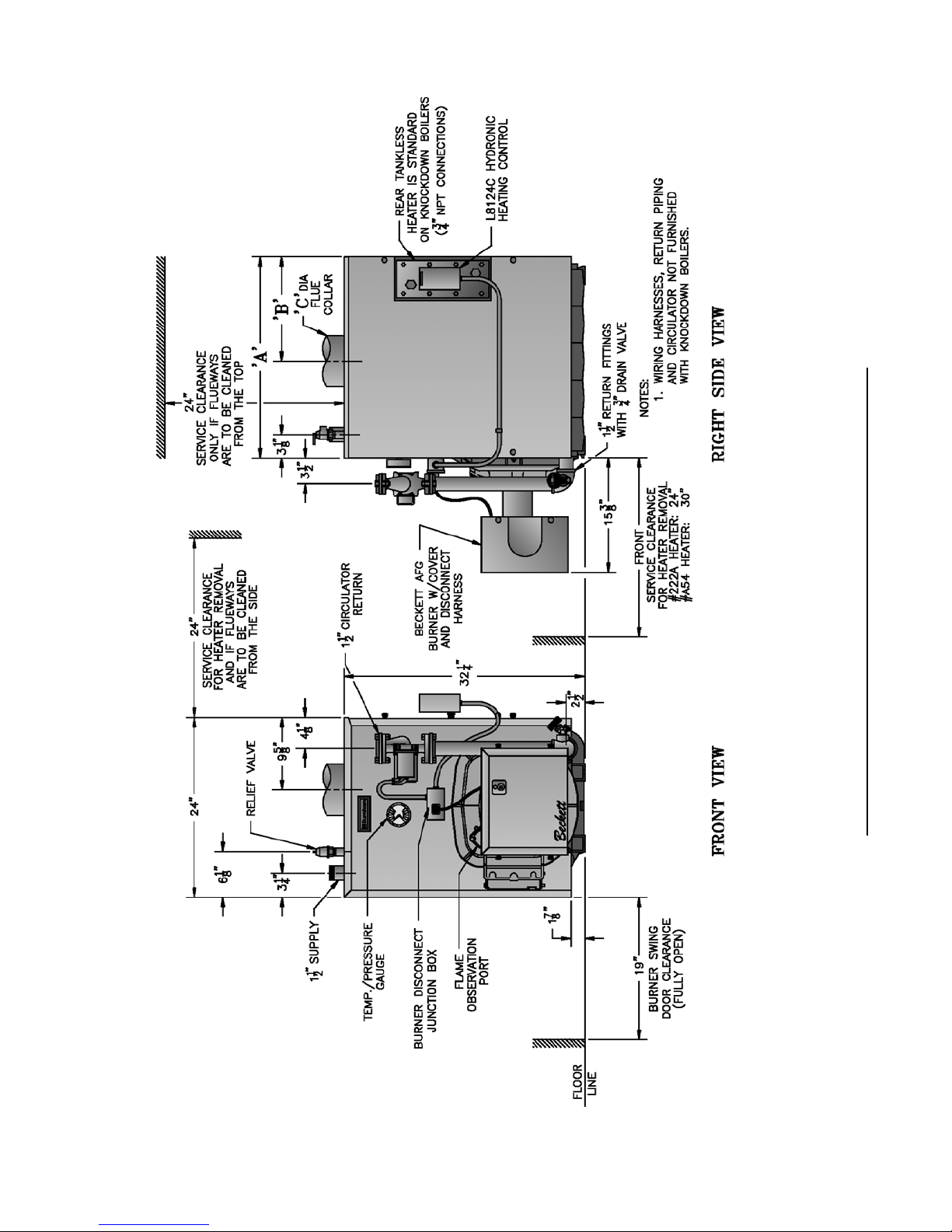
TABLE 1A: DIMENSIONAL DATA (SEE FIGURES 1A THRU 1D)
Boiler
Model No.
Dimensions
See Figures 1A - 1D
Water Content - Gallons
Heat Transfer
Surface Area
- Sq. Ft.
Approximate
Shipping Weight
(LB.)
"A"
"B"
"C"
Steam
Boiler
Water
Boiler
Steam Boiler
V82
12-1/8"
6-5/8"
5"
10.0
450
V83
17-1/8"
9-1/8"
6"
10.3
12.8
15.88
542
V84
22-1/8"
11-5/8"
6"
12.4
15.7
22.92
634
V85
27-1/8"
14-1/8"
7"
14.6
18.5
29.96
726
V86
32-1/8"
16-5/8"
7"
16.7
21.4
37.00
818
V87
37-1/8"
19-1/8"
8"
18.8
24.2
44.04
910
V88
42-1/8"
21-5/8"
8"
20.9
27.1
51.08
1002
V89
47-1/8"
24-1/8"
8"
23.0
30.0
58.12
1094
NOTE: 1
The V82 Boiler is available as a packaged water boiler only.
22Maximum working Pressure: Steam: 15 PSI; Water: 30 PSI Shipped From Factory (Std.),
40 PSI Optional, 50 PSI Optional
Boiler
Model No.
*
Burner Capacity
I=B=R NET Ratings
Minimum Chmney
Requirements
AFUE %
GPH
MBH
DOE Heating
Capacity MBH
Water
MBH
Steam
MBH
Steam
Sq. Ft.
Round
In. Dia.
Rectangle
In. x In.
Height
Ft.
Steam
Water
V82W
0.60
70
61
6
8 x 8
15
82.1
V83W
1.05
147
123
107
6
8 x 8
15
82.6
V83S
V83WM
0.75
105
91
79
68
283
6
8 x 8
15
85.1
86.0
V84W
1.35
189
159
138
7
8 x 8
15
83.2
V84S
V84WM
1.05
147
127
110
95
396
6
8 x 8
15
85.3
86.1
V85W
1.65
231
196
170
7
8 x 8
15
83.9
V85S
V85WM
1.35
189
164
143
123
512
7
8 x 8
15
85.4
86.2
V86W
1.90
266
227
197
8
8 x 8
15
84.6
V86S
V86WM
1.65
231
201
175
151
629
7
8 x 8
15
85.7
86.3
V87S
V87W
2.10
294
252
219
189
787
8
8 x 8
15
84.7
85.0
V88S
2.35
329
266
200
833
8
8 x 12
15
V88W
2.35
329
275
239
8
8 x 12
15
V89S
2.60
364
298
224
933
9
8 x 12
15
V89W
2.60
364
299
260
9
8 x 12
15
*
Boiler Model Suffi x: S=Steam at standard rate, W=Water, WM=Water at minimum rate
Dimensions
Boiler
Model No.
V82
V83
V84
V85
V86
V87
V88
V89
NOTE: 1
See Figures 1A - 1D
"A"
12-1/8"
17-1/8"
22-1/8"
27-1/8"
32-1/8"
37-1/8"
42-1/8"
47-1/8"
The V82 Boiler is available as a packaged water boiler only.
Maximum working Pressure: Steam: 15 PSI; Water: 30 PSI Shipped From Factory (Std.),
40 PSI Optional, 50 PSI Optional
"B"
6-5/8"
9-1/8"
11-5/8"
14-1/8"
16-5/8"
19-1/8"
21-5/8"
24-1/8"
"C"
5"
6"
6"
7"
7"
8"
8"
8"
Water Content - Gallons
Steam
Boiler
10.3
12.4
14.6
16.7
18.8
20.9
23.0
Water
Boiler
10.0
12.8
15.7
18.5
21.4
24.2
27.1
30.0
Heat Transfer
Surface Area
- Sq. Ft.
Steam Boiler
15.88
22.92
29.96
37.00
44.04
51.08
58.12
Approximate
Shipping Weight
(LB.)
450
542
634
726
818
910
1002
1094
TABLE 1B: RATING DATA
Minimum Chmney
Burner Capacity
Boiler
Model No.
*
V82W
V83W
V83S
V83WM
V84W
V84S
V84WM
V85W
V85S
V85WM
V86W
V86S
V86WM
V87S
V87W
V88S
V88W
V89S
V89W
*
Boiler Model Suffi x: S=Steam at standard rate, W=Water, WM=Water at minimum rate
GPH
0.608484
1.05
0.75
1.35
1.05
1.65
1.35
1.90
1.65
2.10
2.35
2.35
2.60
2.60
MBH
147
105
189
147
231
189
266
231
294
329
329
364
364
DOE Heating
Capacity MBH
70
123
91
159
127
196
164
227
201
252
266
275
298
299
I=B=R NET Ratings
Water
MBH
107
138
110
170
143
197
175
219
239
260
61
79
Steam
MBH
68
95
123
151
189
200
224
Steam
Sq. Ft.
283
396
512
629
787
833
933
Requirements
Round
In. Dia.
6
6
6
7
6
7
7
8
7
8
8
8
9
9
Rectangle
In. x In.
8 x 8
8 x 8
8 x 8
8 x 8
8 x 8
8 x 8
8 x 8
8 x 8
8 x 8
8 x 8
8 x 12
8 x 12
8 x 12
8 x 12
Height
Ft.
15
15
15
15
15
15
15
15
15
15
15
15
15
15
AFUE %
Steam
85.1
85.3
85.4
85.7
84.7
Water
82.1
82.6
86.0
83.2
86.1
83.9
86.2
84.6
86.3
85.0
5
6
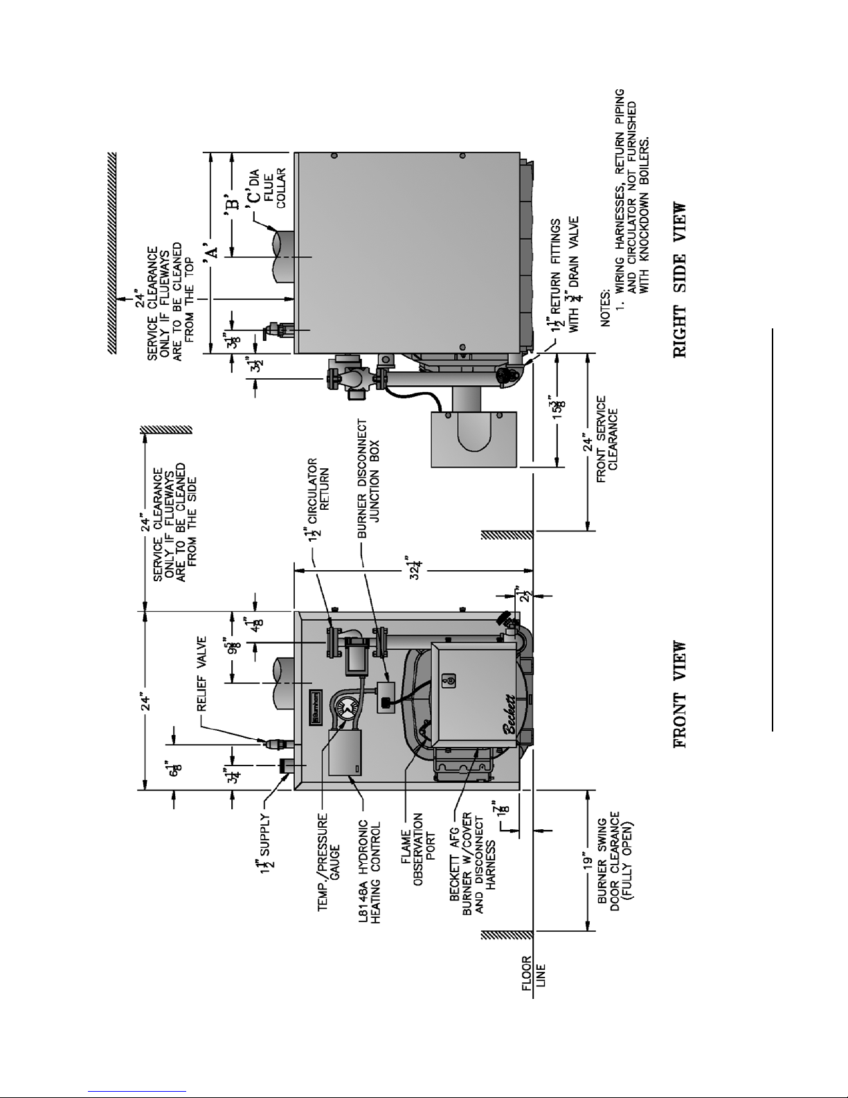
Figure 1A: V82 thru V89 Water Boiler without Tankless Heater
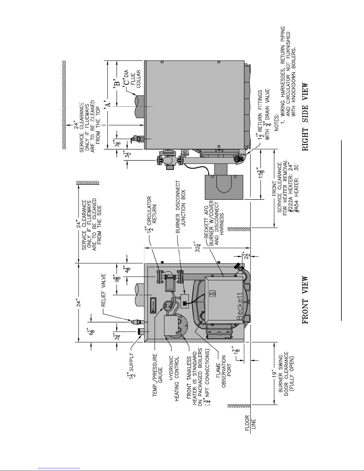
Figure 1B: V83 thru V89 Water Boiler with Front Tankless Heater
7
8
Figure 1C: V83 thru V89 Water Boiler with Rear Tankless Heater
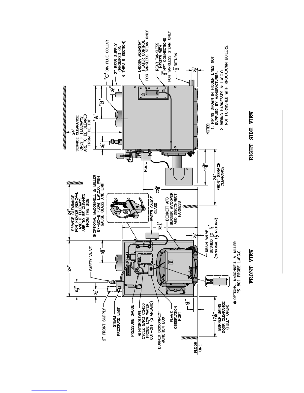
Figure 1D: V83 thru V89 Steam Boiler with or without Tankless Heater
9
SECTION I: PRE-INSTALLATION
A. INSPECT SHIPMENT carefully for any signs of
damage.
1. All equipment is carefully manufactured, inspected
and packed. Our responsibility ceases upon delivery
of crated boiler to the carrier in good condition.
2. Any claims for damage or shortage in shipment
must be fi led immediately against the carrier by the
consignee. No claims for variances from, or shortage
in orders, will be allowed by the manufacturer
unless presented within sixty (60) days after receipt
of goods.
B. LOCATE BOILER in front of fi nal position before
removing crate. See Figures 1A thru 1D.
1. LOCATE so that vent pipe connection to chimney
will be short and direct.
2. BOILER IS SUITABLE FOR INSTALLATION
ON COMBUSTIBLE FLOOR. Boiler cannot be
installed on carpeting.
3. FOR BASEMENT INSTALLATION, provide
a solid elevated base, such as concrete, if fl oor is
not level, or if water may be encountered on fl oor
around boiler.
4. PROVIDE SERVICE CLEARANCE of at least
24” clearance from front jacket panel for servicing
and removal of front tankless heater (increase to
30" for #A54 heater). If boiler is equipped with
a rear tankless heater, provide at least 24" service
clearance on the right side of the boiler. Boiler
fl ueways may be cleaned either from the top or from
the right side. Provide at least 24" clearance from
either the right side of the boiler or the top of the
boiler for cleaning fl ueways.
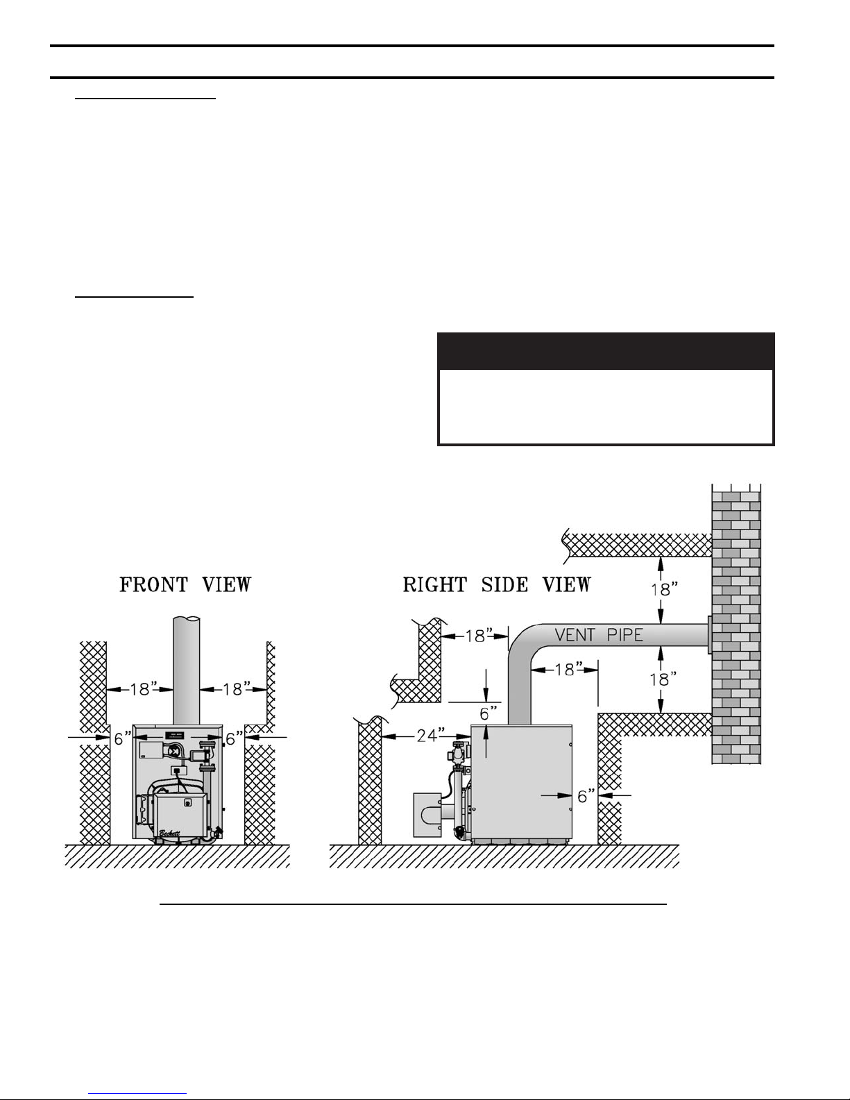
5. For minimum clearances to combustible materials.
See Figure 2.
ECITON
tnevllawelgnisrofsignitnevotecnaraelC
yamecnaraelc,desusitnevLepyTfI.epip
ehtybderiuqermuminimehtotdecudereb
.rerutcafunamepiptnev
Figure 2: Minimum Installation Clearances To Combustible Materials (Inches)
NOTES:
1. Listed clearances comply with American
National Standard ANSI/NFPA 31, Installation of
Oil Burning Equipment.
2. V8 Series boilers can be installed in rooms with
clearances from combustible material as listed
10
above. Listed clearances cannot be reduced for
alcove or closet installations.
3. For reduced clearances to combustible material,
protection must be provided as described in the
above ANSI/NFPA 31 standard.

C. PROVIDE COMBUSTION AND VENTILATION
AIR. Local and National Codes may apply and should
be referenced.
GNINRAW
noitalitnevdnanoitsubmocetauqedA
reporperussaotdedivorpebtsumria
efasniatniamotdnanoitsubmoc
etriatneibma
yhfosecruos
.derots
1. Determine volume of space (boiler room). Rooms
communicating directly with the space in which
the appliances are installed, through openings not
furnished with doors, are considered a part of the
space.
Volume(ft3) = Length(ft) x Width(ft) x Height(ft)
2. Determine total input of all appliances in the space.
Add inputs of all appliances in the space and round
the result to the nearest 1000 BTU per hour.
3. Determine type of space. Divide Volume by total
input of all appliances in space. If the result is
greater than or equal to 50 ft3/1000 BTU per hour,
then it is considered an unconfi ned space. If the
result is less than 50 ft3/1000 BTU per hour then the
space is considered a confi ned space.
4. For boiler located in an unconfi ned space of a
conventionally constructed building, the fresh
air infi ltration through cracks around windows
and doors normally provides adequate air for
combustion and ventilation.
5. For boiler located in a confi ned space or an
unconfi ned space in a building of unusually tight
construction, provide outdoor air.
a. Outdoor air for combustion may be provided
with an optional Burnham V8 Inlet Air
Accessory Kit, Part Number 611280031 (ONLY
AVAILABLE WITH BECKETT BURNER).
See Section VII for installation details.
or
.serutarepm
roenilosagerehwreliobllatsnitonoD
ro,sdiuqilrosropavelbammalfrehto
,sehcaelb.e.i(snobracord
rodesuera).cte,srenetfoscirbaf
b. Outdoor air may be provided with the use of two
permanent openings which communicate directly
or by duct with the outdoors or spaces (crawl or
attic) freely communicating with the outdoors.
Locate one opening within 12 inches of top
of space. Locate remaining opening within 12
inches of bottom of space. Minimum dimension
of air opening is 3 inches. Size each opening per
following:
i. Direct communication with outdoors.
Minimum free area of 1 square inch per
4,000 BTU per hour input of all equipment
in space.
ii. Vertical ducts. Minimum free area of 1
square inch per 4,000 BTU per hour input of
all equipment in space. Duct cross-sectional
area shall be same as opening free area.
iii. Horizontal ducts. Minimum free area of 1
square inch per 2,000 BTU per hour input of
all equipment in space. Duct cross-sectional
area shall be same as opening free area.
Alternate method for boiler located within
confi ned space. Use indoor air if two
permanent openings communicate directly
with additional space(s) of suffi cient volume
such that combined volume of all spaces
meet criteria for unconfi ned space. Size each
opening for minimum free area of 1 square
inch per 1,000 BTU per hour input of all
equipment in spaces, but not less than 100
square inches.
6. Louvers and Grilles of Ventilation Ducts
a. All outside openings should be screened and
louvered. Screens used should not be smaller
than 1/4 inch mesh. Louvers will prevent the
entrance of rain and snow.
b. Free area requirements need to consider the
blocking effect of louvers, grilles, or screens
protecting the openings. If the free area of the
louver or grille is not known, assume wood
louvers have 20-25 percent free area and metal
louvers and grilles have 60-75 percent free area.
c. Louvers and grilles must be fi xed in the open
position, or interlocked with the equipment to
open automatically during equipment operation.
11
SECTION II: KNOCKDOWN BOILER ASSEMBLY
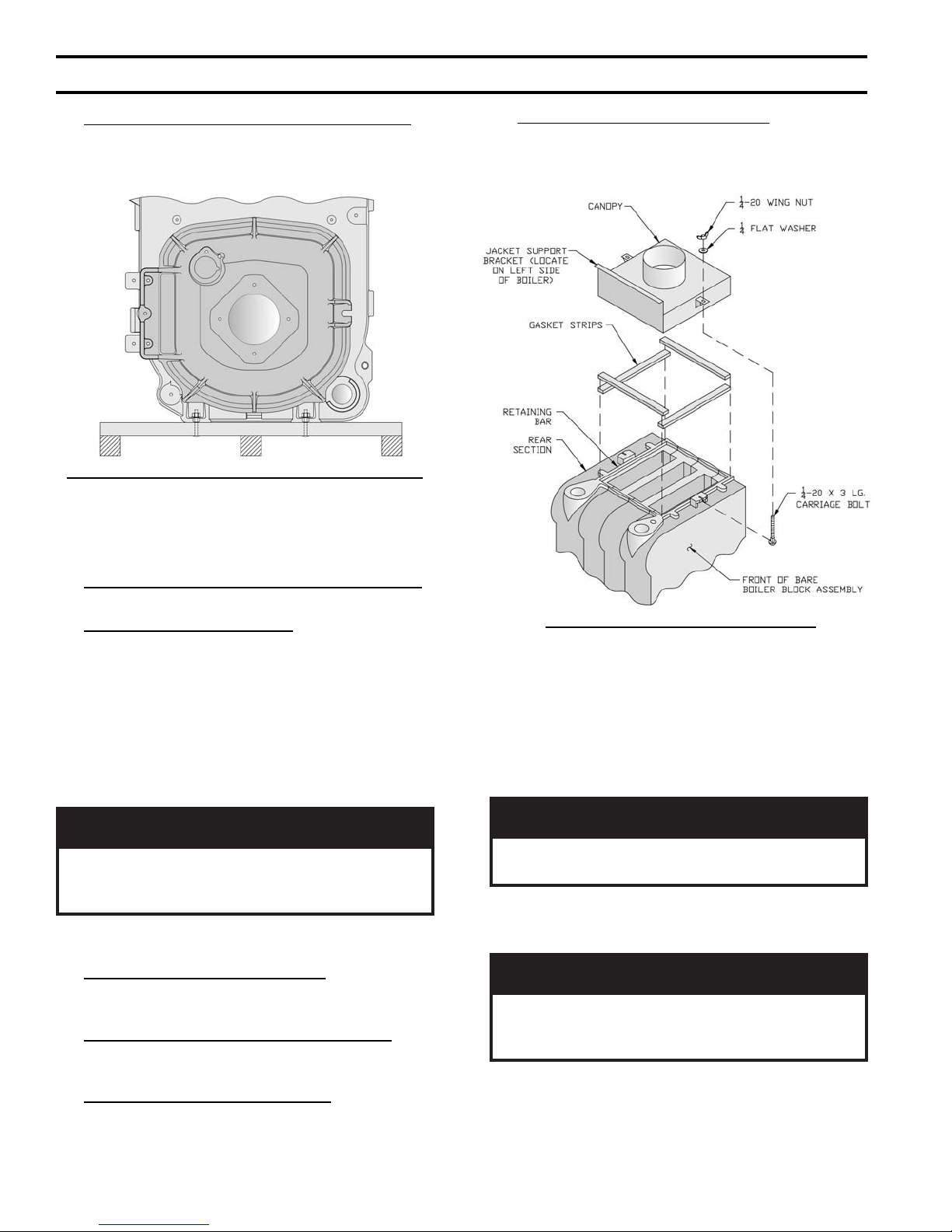
A. REMOVAL OF BARE BOILER FROM SKID
1. Boiler is secured to skid with 4 bolts, 2 in front and
2 in rear of shipping skid, see Figure 3. Remove all
bolts.
Figure 3: Knockdown Boiler Removal from Skid
2. Tilt boiler to right and to rear. Using right rear leg
as pivot, rotate boiler 90° in a clockwise direction,
and lower left side of boiler to fl oor. Tilt boiler and
remove skid.
B. MOVE BOILER TO PERMANENT POSITION
by sliding or walking.
C. TEST BOILER FOR LEAKS before installing
controls, trim, and jacket, and before connecting to
heating system.
1. Loosen nuts on tie rods until only fi nger tight.
2. Install pressure gauge (at least 50 PSI capacity),
a hose to the city water and a valve in the supply
tapping. Plug remainder of tappings.
3. Fill boiler with water and apply a pressure of at least
10 PSI but no more than 50 PSI gauge pressure.
G. INSTALL AND SECURE CANOPY with gasket
and hardware provided to ensure gas tight seal — see
Figure 4.
Figure 4: Boiler Canopy Installation
1. Cut two (2) strips 13 ¾” long from the roll of gasket
insulation. Place one (1) strip across the top of the
front section and the other across the rear section as
shown in Figure 4.
2. Cut the remainder of the roll into two (2) equal
pieces. Place each piece along the sides, allowing
the ends to overlap the front and rear pieces.
GNINRAW
.riadezirusserphtiwskael
4. Examine boiler carefully inside and outside for leaks
or damage due to shipment or handling.
D. DRAIN WATER FROM BOILER. Remove gauge,
valve and plugs from those tappings to be used. Leave
other tappings plugged or bushed according to Figure 5.
E. INSPECT JOINTS BETWEEN SECTIONS. All
joints are factory sealed. If there are any spaces due to
shipment or handling, seal them with boiler putty.
F. INSPECT FLUE COVER PLATES for tightness.
If loose, retighten mounting hardware. If fl ue plate or
sealing rope is damaged, repair or replace as needed.
12
NOITUAC
reliobedisnitfelriaonsierehttahterussA
roftsettonoD.skaelrofgnikcehcnehw
.teksag
3. Position canopy body within the retaining bar which
borders the fl ueway openings on top of the bare
boiler block assembly.
ybegakcolbyaweulfynawollatonoD
ECITON
tfelgnicafebtsumtekcarbtroppustekcaJ
tonlliwtekcaJ.4erugiFees-reliobfoedis
rbfitif
4. Secure canopy to boiler with two (2) 1/4" - 20 x 3"
long carriage bolts, 1/4" fl at washers and 1/4" - 20
wing nuts provided.
.yltcerrocdetneirotonsitekca
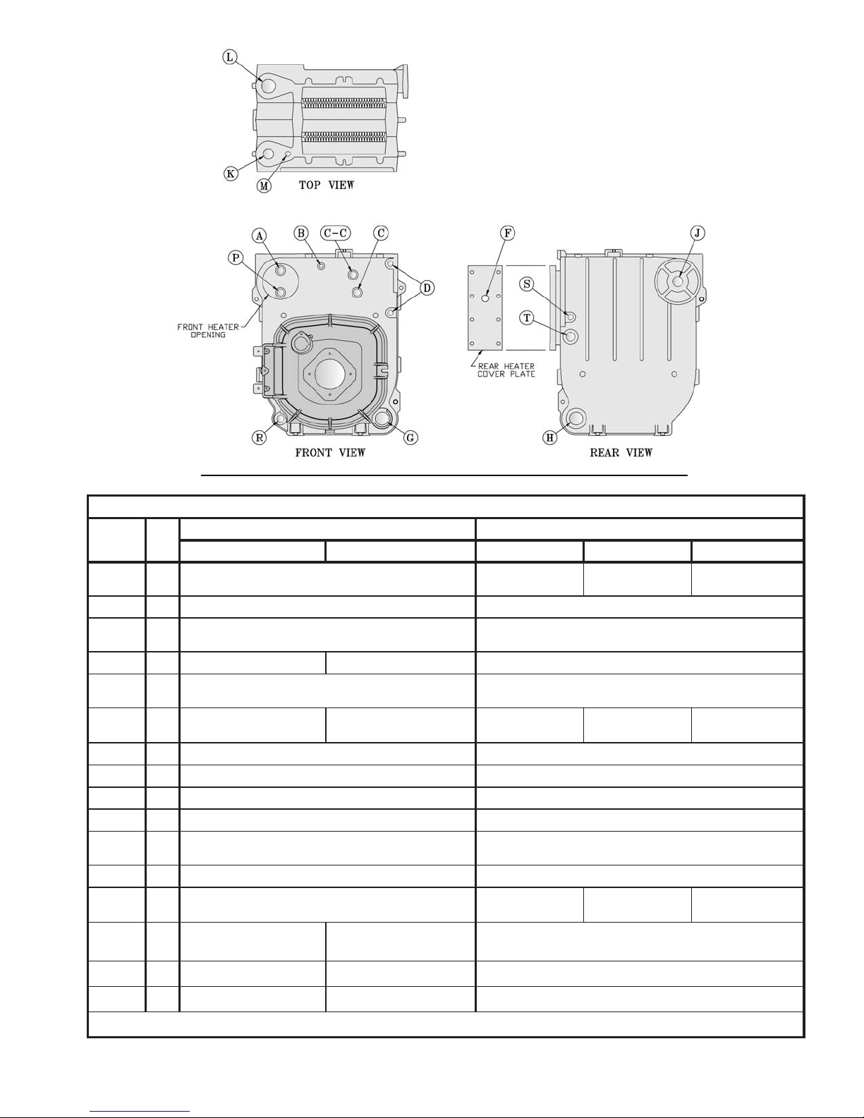
gnippaT
noitacoL
A"¾
B"¼
C"¾
C-C"¾
D"½
F"¾
G"½1
H"½1
J"½1
K"2
L"2
M"¾
P"¾
R"¾
Figure 5: Boiler Tapping Locations and Usage (Knockdown Boilers Only)
SGNIPPATFOESOPRUP
eziS
TPN
retaeH-noNretaeH/wretaeH-noNretaeHtnorFretaeH
gulPhsulFgulPhsulFA/N
A/NlortnoCgnitarepOA6004LA/NA/N
deggulP-gnippaT.xuA
)nruteRtceridnI(
relioBmaetSrelioBretaW
)OCWLeborP(timiLerusserP
)OCWLtaolF(deggulP
eguaGerusserP eguaGerusserP/erutarepmeT
.dtSOCWLeborP
)OCWLtaolF(deggulP
)OCWLeborP(ssalGeguaGretaW
nruteRdeggulP
deggulP-ffowolBecafruS gulPhsulF
)noitceS9urht3(ylppuStnorF )noitceS9urht3(ylppuStnorF
evlaVytefaS evlaVfeileR
deggulP-gnippaTyrailixuA
)taolF(OCWLdna,lorterusserP,ssalGeguaGretaW
)nruteRlanoitpO(evlaVniarDrof"¾otdehsuB nruteR
)noitceS5urht3(ylppuSdnoceSlanoitpO,deggulP
)noitceS9urht6(ylppuSdnoceSderiuqeR
deggulP-gnippaT.xuA
)nruteRtceridnI(
*
A8418L
lortnoCgnitarepO
-gnippaT.xuA
deggulP
raeR
C4218L
lortnoCgnitarepO
A/N
A/N
gulPhsulF
C4218L
lortnoCgnitarepO
)noitceS9urht3(deggulP
A/N
deggulP-gnippaTyrailixuA
-gnippaT.xuA
deggulP
S"½
T"1
*
retaeHsselknaTfoueilnI
timiLtceridnI
ylppuStceridnI
timiLtceridnI
*
ylppuStceridnI
*
A/N
A/N
13
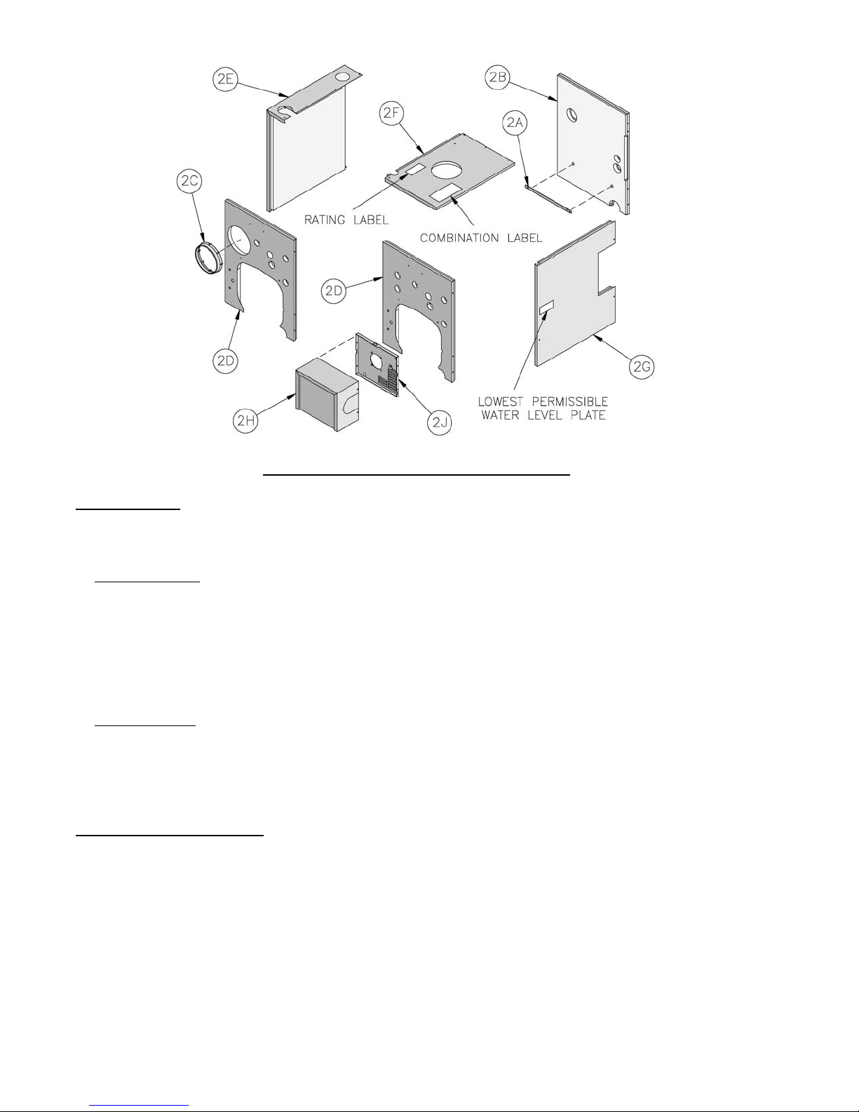
Figure 6: Knockdown Boiler Jacket Assembly
H. INST ALL TRIM. The following steam or water trim
will be concealed or inaccessible after boiler jacket is
installed, see Figure 5 for boiler tapping locations and
usage.
1. STEAM BOILER — Top tappings:
a. Tapping "L" — Install 2" NPT plug in rear
section top supply tapping on boiler sizes V83
thru V85, if only one supply riser is used.
b. Tapping “M” — Install ¾” NPT coupling and
¾” NPT x 8” long nipple into ¾” NPT tapping
located next to front section top supply tapping
— all boiler sizes.
2. WATER BOILER — Top tappings:
a. Tapping “L” — Install 2” NPT plug in rear
section top supply tapping — all boiler sizes.
b. Tapping “M” —Install ¾” NPT x 8” long nipple
into ¾” NPT tapping located next to front section
top supply tapping — all boiler sizes.
I. INSTALL BOILER JACKET. (See Figure 6).
1. Remove burner swing door and hinge assembly.
Remove one (1) 5/16"-18 fl ange nut and washer
from right side latching stud and one (1) 5/16"-
18 x 3½" cap screw on left side used for securing
burner swing door to the boiler section. Swing door
open and remove 5/16" hairpin cotter from rear
hinge pin. While holding swing door remove hinge
pin and set door aside. Remove two (2) 5/16" -
18 x ¾" long cap screws securing the hinge bracket
to the boiler section.
2. Install jacket rear panel support bracket. (See Figure
6, Item 2A). Align bracket with two (2) 5/16" - 18
tapped holes in rear section and secure with two (2)
5/16" - 18 x 1/2" long cap screws.
3. Install jacket rear panel. (See Figure 6, Item 2B).
Align holes in jacket rear panel and support bracket.
Secure with two (2) #8 x 1/2" long sheet metal
screws.
4. Jacket Front Panel
a. Install black plastic collar extension to jacket
front panels for 7-13/16" diameter tankless
heater opening. (See Figure 6, Items 2C and
2D). Engage two (2) of the collar retaining
tabs over raw edge of jacket opening. Provide
support behind the panel with one hand while
applying pressure on collar to snap each tab
over edge of opening until all eight (8) tabs are
securing collar.
b. Install jacket front panel. Locate two (2) 11/32"
diameter holes, one round, one obround, on front
panel approximately 16” up from the bottom of
the panel. Align these holes with the similarly
located 5/16" - 18 tappings on the front section.
Secure with two (2) 5/16" - 18 x 1/2" long cap
screws.
5. Install jacket left side panel. (See Figure 6, Item
2E). Fold panel at perforation keeping insulation
inward. Align left side panel mounting holes with
the front and rear panel holes. Secure with #8 x ½”
long sheet metal screws.
14
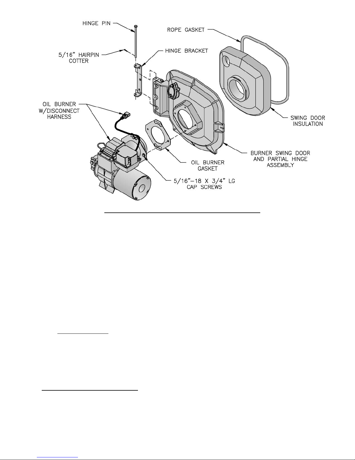
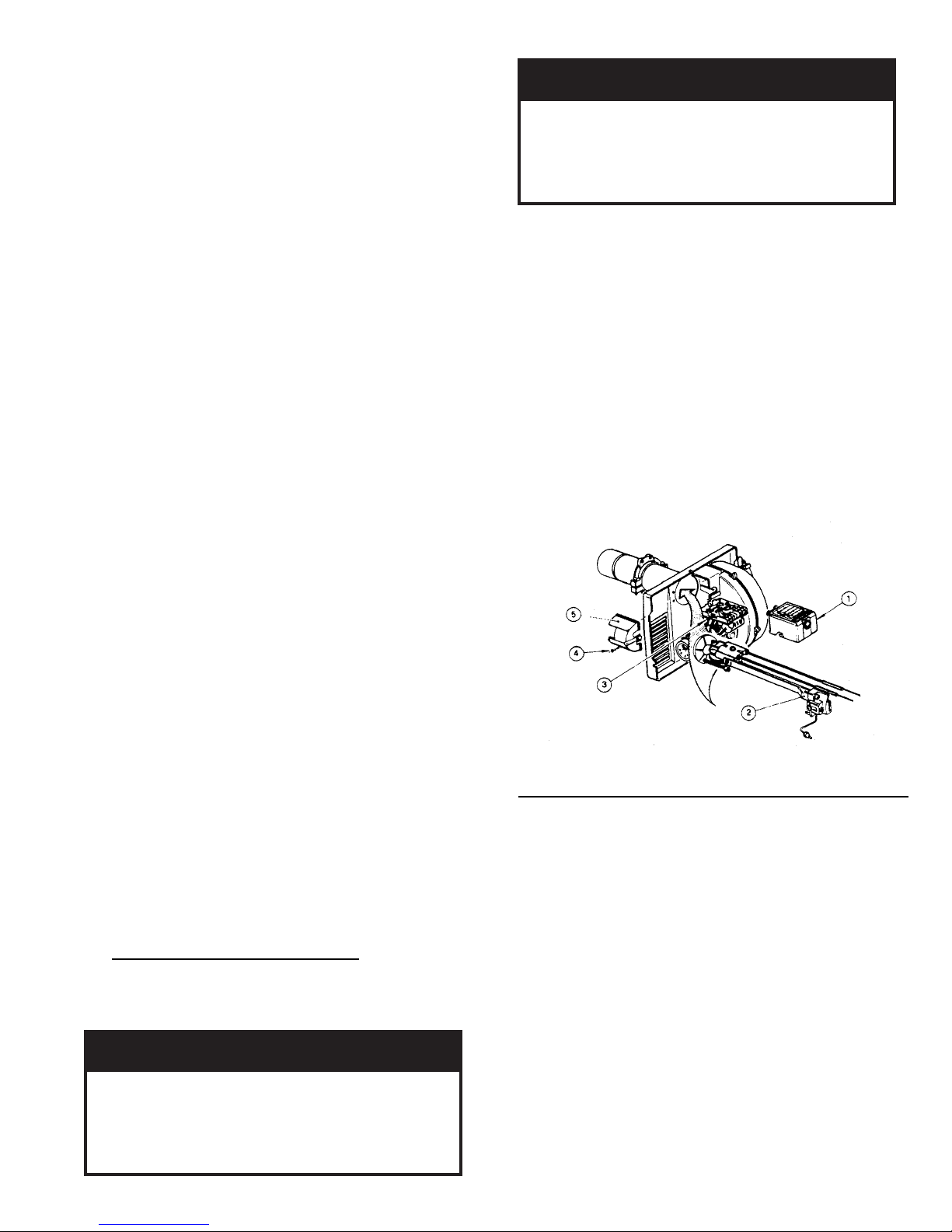
Figure 7: Oil Burner Installation (Beckett Burner Shown)
6. Install jacket top panel. (See Figure 6, Item 2F).
Place jacket top panel on boiler and secure to front,
rear and left side panels with #8 x ½” long sheet
metal screws.
7. Install jacket right side access panel. (See Figure
6, Item 2G). Align right side panel mounting holes
with front and rear panel holes. Secure with #8 x ½”
long sheet metal screws.
8. Attach the labels shipped in the instruction envelope
as follows:
a. Locate both the Rating Label and Combination
Warning Label (P/N 8142803). Remove paper
backing from the labels and apply to the jacket
top panel in approximate locations shown in
(Figure 6, Item 2F).
b. On steam boilers only; locate Lowest Permissible
Water Level Plate (Form No. 1204 shipped in
Steam Trim Carton). Align plate with two 1/8"
diameter holes located near the front edge; in
line with the lower sight glass tapping, of the
jacket right side access panel. Attach plate with
two (2) #8 x 1/2" long sheet metal screws. (See
Figure 6, Item 2G).
J. INSTALL BECKETT OIL BURNER. (See Figure
7).
1. Check target wall and combustion chamber blanket.
If any damage or movement occurred during
shipment, replace as needed.
2. Locate burner swing door and hinge assembly
removed in Paragraph I, No. 1. Check the burner
swing door insulation and rope gasket for damage
and adhesion. If damaged, replace insulation or
gasket. If insulation or gasket is loose, reattach to
swing door with RTV 732 or 736 silicone caulk.
3. Install burner swing door in reverse order from
Paragraph I, No. 1.
4. Use the following procedure to properly close
and secure the burner swing door after it has been
removed and re-installed for Field Assembly
(Knockdown Boiler) or opened for inspection,
cleaning or fi eld service (refer to Figures 11A and
11B):
Step 1. Lift the door up unto the built-in cast ramp/
door rest (protruding from the bottom of the front
section casting - see Figure 11A), while rotating
the articulated hinge and door to the right and
engaging the slot (on right side of door) unto the
5/16" stud protruding from the front section.
Step 2. Use one hand to help hold door in position
by applying pressure directly to the door while
re-installing the securing hardware with your
opposite hand. Always install right side
latching hardware (5/16" fl ange nut and
fl at washer) fi rst, then install left side hinge
hardware (5/16" x 3-1/2" lg. hex head fl ange
bolt) second. Apply additional pressure while
hand tightening the hardware as far as possible,
then release the pressure.
15

ECITON
ekamroodgniwsrenrubgnirucesnehW
Step 3. Use a hand wrench to tighten door hardware
and always start with the right side fl ange
nut fi rst (see fi gure 11B). Use an alternating
tightening method from right side fl ange nut
to left side fl ange bolt to tighten door equally
until sealed without applying excessive torque.
Never tighten left side fl ange bolt fi rst or tighten
either piece of hardware 100% without using the
alternating tightening method described above.
5. Place oil burner gasket on burner and align holes.
NOITUAC
.teksagtuohtiwrenrubllatsnitonoD
6. Insert oil burner into the opening of the burner
swing door. Align holes and install four (4) 5/16”
- 18 x ¾” long cap screws. Level burner and fully
tighten all four (4) screws.
7. Install oil nozzle in burner, inspect electrodes and
head setting.
REGNAD
elzzonlionaevahtonseodrenrubehT
deilppus,elzzonlioreporpehT.dellatsni
elzzonehtnidellatsniebtsum,esool
httuohtiwrenrubetarepotonoD.rotpada
.renrubehtnidellatsnielzzonlioreporp
e. Remove nozzle line electrode assembly.
f. Remove Beckett MD(V1) or MB(L1) Head.
g. Remove plug from nozzle adapter and install
.sedishtobnoyllauqeni-nwardsirooderus
K. INSTALL CARLIN 102CRD OIL BURNER. (See
e
the proper nozzle. Refer to Table 6 for proper
nozzle. The nozzle must be securely installed
to assure leak free joints between the nozzle and
adapter. When installing the nozzle, be careful
not to bump or move the burner electrodes.
h. Inspect and measure burner electrodes. Refer
to Figure 27A for the proper electrode setting.
Readjust electrode setting to the proper
dimensions if necessary.
i. Reinstall Beckett MD(V1) or MB(L1) Head.
j. Reinstall nozzle line electrode assembly.
k. Connect copper connector tube.
l. Inspect Beckett head setting on left side of
burner by insuring the blue line MD(V1) or the
line on the label MB(L1) are aligned, readjust if
necessary.
m. Tighten knurled nut.
n. Swing igniter closed, rotate tabs and tighten two
(2) igniter screws.
o. Replace burner cover and tighten burner cover
knobs.
Figure 7).
Follow instructions in Paragraph J, Steps 1 through 6.
7. Install oil nozzle in burner, inspect electrodes and
head setting.
REGNAD
16
a. Select the proper oil nozzle for the installation.
Two (2) oil nozzles are supplied loose with each
knockdown V83 - V86 boiler. Either nozzle may
be used with water boilers. Steam boilers must
use the lower input nozzle. The lower input
nozzle will provide greater boiler effi ciency
and for steam boilers, reduce boiler corrosion.
However, boiler output will be reduced. Refer
to Table 1B for ratings. The nozzle input is
stamped on the hex fl at of the nozzle.
NOITUAC
ehttadetarepoebylnotsumsreliobmaetS
etargnirifehtgnisaercnI.tupnirewol
detareleccanitluserlliwtupnisihtevoba
ytnarrawehtdiovlliwdnanoisorrocreliob
.reliobehthtiwdedivorp
b. Loosen burner cover knobs and remove cover.
c. Loosen two (2) igniter latching screws, rotate
tabs and swing open igniter about hinge.
d. Loosen knurled nut and disconnect copper
connector tube.
elzzonlionaevahtonseodrenrubehT
deilppus,elzzonlioreporpehT.dellatsni
elzzonehtnidellatsniebtsum,esool
e
httuohtiwrenrubetarepotonoD.rotpada
.renrubehtnidellatsnielzzonlioreporp
NOITUAC
ehttadetarepoebylnotsumsreliobmaetS
etargnirifehtgnisaercnI.tupnirewol
detareleccanitluserlliwtupnisihtevoba
ytnarrawehtdiovlliwdnanoisorrocreliob
.reliobehthtiwdedivorp
Steam Boilers Only
Knockdown V87 - V89 boilers are provided with
one nozzle, installed in the burner, that provides
the same fi ring rate as the water boiler of the
same size.
a. Installation/Removal of Drawer Assembly
i. Loosen screws, rotate latches and swing
open the transformer.
Disconnect the fl ared fi tting to the oil line
and remove the aluminum thumb-nut from
the nozzle line. Remove the combustion
head assembly from the air tube. Rotating
the assembly upside down will ease
removal. Inspect the nozzle for size and
type, refer to Table 6 of this manual.
ii. To change a nozzle, loosen the clamp screw
on the retention ring assembly and slide the
retention ring off the adaptor.
Install and tighten the proper nozzle in
the adaptor. See Table 6 of this manual.
Be careful not to damage the electrode
insulators or to bend the wires.
iii. Replace the retention ring assembly, slipping
one of the riveted arms through the 1/8-inch
gap between the electrode tips. This arm
should be straight up. Also, be sure that the
retention ring clamp is tight against the
shoulder on the adaptor. Then tighten the
clamping screw.
iv. Check the electrode settings specifi ed as
follows and shown in Figure 27B. 1/8-inch
gap, 1/4-inch above the nozzle centerline,
and 3/16-inch ahead of the nozzle tip.
v. Re-install the combustion head assembly
into the air tube. It may be necessary to turn
nozzle line assembly upside down to ease
insertion into the air tube. Then the threaded
adapter on the end of the nozzle line is
passed through the opening in the left side of
the housing.
vi. Run the aluminum (knurled) thumb-nut onto
the nozzle line and tighten hand-tight.
vii. Connect the fl ared fi tting on the copper oil
line to the nozzle line and tighten.
viii. Swing the transformer to the closed position,
rotate latches and tighten screws.
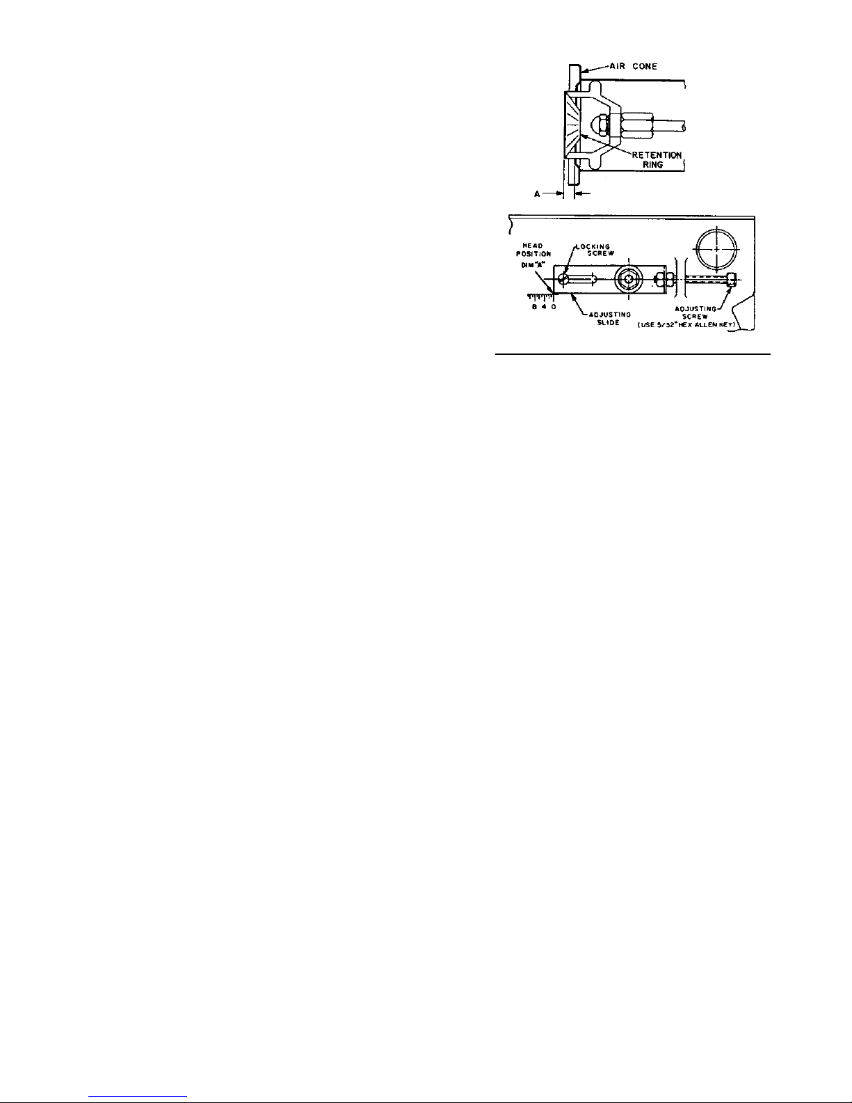
b. Combustion Head Setting/Adjustment
i. Verify combustion head setting, refer to
Table 6 of this supplement. Read the scale
embossed in the housing, which is calibrated
in 1/16-inch divisions (dimension ‘A’)
the position of the fl ame retention ring in
relation to the air cone can be determined at
a glance. Refer to Figure X.
ii. By moving the electrode and combustion
head assembly forward or backward, the
location of the fl ame retention ring relative
to the throttle ring can be controlled. Refer
to Figure 7A.
By loosening the locking screw and thumb-
nut and turning the adjusting screw using a
5/32-inch allen wrench, the assembly can be
Figure 7A: Combustion Head Adjustment
moved to the required position.
Turn the adjusting crew clockwise to move
the combustion head forward, increasing the
‘A’ dimension, counterclockwise will pull
the head back, decreasing the ‘A dimension.
To lock in place, fi rst tighten the thumb-nut
and then the locking screw.
c. Initial Air Shutter/Band Setting
i. The air shutter has a pointer which indicated
the percent of opening against a calibrated
scale (9 = 90%, fully open = 100%). The
setting is locked in place by a screw just
above the fuel unit.
ii. The air band is adjusted by loosening the
screw, rotating the air band and then locked
in place after fi nal adjustment. Refer to
Table 6 of this manual for initial settings.
iii. The burner is now set at the approximate
air band setting for the gallonage indicated.
During fi nal adjustment, using combustion
testing equipment, the air band may need
minor adjustment to achieve the desired
effi ciency.
Water Boilers Only
Knockdown V87 - V89 boilers are provided
with one nozzle, installed in the burner, that
provides the same fi ring rate as the steam
boiler of the same size.
Inspect the installed nozzle and assure that
the nozzle is the correct size and type as
specifi ed in Table 6 of this manual. The
nozzle input is stamped on the hex fl at of the
nozzle.
Refer to Paragraph K, 7, a for burner drawer
assembly removal.
17

L. INSTALL CARLIN ELITE EZ OIL BURNER.
(See Figure 7).
Follow instructions in Paragraph J, Steps 1 through 6.
7. Inspect oil nozzle, electrodes and head setting/
change fi ring rate.
REGNAD
elzzonlionaevahtonseodrenrubehT
deilppus,elzzonlioreporpehT.dellatsni
elzzonehtnidellatsniebtsum,esool
.renrubehtnidellatsnielzzonlioreporp
NOITUAC
etargnirifehtgnisaercnI.tupnirewol
detareleccanitluserlliwtupnisihtevoba
.reliobehthtiwdedivorp
Steam Boilers Only
Steam boilers must use the lower input nozzle.
The lower input nozzle will provide greater
boiler effi ciency and for steam boilers, reduce
boiler corrosion. However, boiler output will be
reduced.
Burners for knockdown V83 - V86 steam boilers
are shipped with the lower (standard) fi ring rate
nozzle installed. Knockdown V87 - V89 boilers
are provided with one nozzle, installed in the
burner, that provides the same fi ring rate as the
water boiler of the same size.
a. Installation/Removal of Drawer Assembly
i. Loosen screws, rotate latches and swing
open the transformer.
ii. The combustion head assembly can be
removed with the blower wheel access cover
in place or removed. If the access cover is
removed, the head assembly will not have to
be rotated.
Disconnect the fl ared fi tting to the oil line
and remove the aluminum thumb-nut from
the nozzle line. Remove the combustion
head assembly from the air tube. Rotating
the assembly upside down will ease
removal.
iii. Loosen the clamp screw on the retention
ring assembly and slide the retention ring off
the adaptor.
Install and tighten the proper nozzle in
the adaptor. See Table 6 of this manual.
Be careful not to damage the electrode
insulators or to bend the wires.
iv. Replace the retention ring assembly, slipping
one of the riveted arms through the 1/8-inch
gap between the electrode tips. This arm
should be straight up. Also, be sure that
the retention ring clamp is tight against the
shoulder on the adaptor. Then tighten the
clamping screw.
v. Check the electrode settings specifi ed as
follows and shown in Figure 27C. 1/8-inch
gap, 1/4 to 5/16-inch above the nozzle
centerline, and fl ush to 1/16-inch ahead of
ehttuohtiwrenrubetarepotonoD.rotpada
ehttadetarepoebylnotsumsreliobmaetS
ytnarrawehtdiovlliwdnanoisorrocreliob
b. Combustion Head Positioning Bars
the nozzle tip.
vi. Re-install the combustion head assembly
holding it upside down while inserting
into the housing. The fl ame retention ring
end of the assembly must be lifted and
guided through the throttle cone (a reduced
diameter) in the end of the air tube. DO
NOT FORCE IT.
vii. After attaching the proper positioning bar,
refer to Paragraph 7,b, run the thumb-nut
onto the nozzle line and tighten it lightly.
Connect the fl ared fi tting on the copper oil
line to the nozzle line and tighten.
i. The Elite EZ-1HP and EZ-2HP burners are
supplied with the proper positioning bar
installed onto the housing that matches the
high (standard) input oil nozzle installed in
the burner. A second positioning bar and
nozzle for the lower (minimum) fi ring rate
is shipped loose for the V83-V86 models,
attached the burner.
Verify that the installed positioning bar
matches the high input oil nozzle installed
in the burner or replace them both with the
nozzle and positioning bar that matches
the lower fi ring rate, refer to Table 6 of this
manual.
The remaining bar(s) should be placed in
the rear of the housing or junction box for
future use in the event the fi ring rate must be
changed.
In the case of the EZ-1HP, the proper head
positioning bar is still matched by the size
of the nozzle, not the input. For example, if
nozzle size is 0.75 GPH, input @ 150 psi is
approximately 0.90 GPH and the proper bar
is 0.75 GPH.
ii. Model EZ-1HP Positioning Bars: 0.50
GPH, 0.60-0.65 GPH, 0.75 GPH, 0.85-1.00
GPH, 1.10-1.25 GPH, 1.35-1.50 GPH, 1.65
GPH.
iii. Model EZ-2HP Positioning Bars: 1.50
GPH, 1.65-1.75 GPH, 2.00 GPH, 2.25 GPH.
18
c. Initial Air Band Setting
i. The nozzle size in GPH INPUT is printed
directly on the air band. Loosen the locking
screw, move the air band until the pointer
on the air shutter and housing lines up with
the appropriate GPH INPUT. Tighten the
locking screws.
ii. The Elite burners use calibrated air bands
marked in nozzle sizes. Models EZ-1HP
and EZ-2HP have air bands calibrated to
deliver the proper amount of air for their
specifi c pump pressure. The air bands on
H.P. models are designed to be set by the
rating stamped on the nozzle.
iii. The burner is now set at the approximate
air band setting for the gallonage indicated.
During fi nal adjustment, using combustion
testing equipment, the air band may need
minor adjustment to achieve the desired
effi ciency.
Water Boilers Only
Select the proper oil nozzle for the installation.
Burners for knockdown V8 water boilers are
shipped with the high (standard) input oil nozzle
installed in the burner.
A second oil nozzle for the lower (minimum)
fi ring rate is shipped loose for the V83 - V86
models, attached to the burner. Either nozzle
may be used with water boilers. The lower
(minimum) input nozzle will provide greater
boiler effi ciency. However, boiler output will be
reduced. Refer to Table 1B for fi ring rates. If
the higher rate is desired, inspect the installed
nozzle and assure that the nozzle is the correct
size and type as specifi ed in Table 6 of this
manual. The nozzle input is stamped on the hex
fl at of the nozzle.
If the lower (minimum) input is desired, remove
the nozzle which was factory installed. Locate
the lower (minimum) fi ring rate nozzle that is
supplied loose. Confi rm the nozzle is the proper
size and type for the lower fi ring rate as specifi ed
in Table 6 of this manual. Install the proper
nozzle in the burner nozzle adaptor.
Refer to Step 7a for burner drawer assembly
removal.
M. INSTALL RIELLO OIL BURNER. (See Figure 7).
Follow instructions in Paragraph J, Steps 1 through 6.
7. Install oil nozzle in burner, inspect electrodes and
head setting.
REGNAD
elzzonlionaevahtonseodrenrubehT
deilppus,elzzonlioreporpehT.dellatsni
elzzonehtnidellatsniebtsum,esool
ehttuohtiwrenrubetarepotonoD.rotpada
.renrubehtnidellatsnielzzonlioreporp
NOITUAC
ehttadetarepoebylnotsumsreliobmaetS
etargnirifehtgnisaercnI.tupnirewol
detareleccanitluserlliwtupnisihtevoba
ytnarrawehtdiovlliwdnanoisorrocreliob
.reliobehthtiwdedivorp
Steam Boilers Only
Steam boilers must use the lower input
nozzle. The lower input nozzle will provide
greater boiler effi ciency and for steam
boilers, reduce boiler corrosion. However,
boiler output will be reduced.
Burners for knockdown V83 - V86 steam
boilers are shipped with the lower (standard)
fi ring rate nozzle installed. Knockdown
V87 - V89 boilers are provided with one
nozzle, installed in the burner, that provides
the same fi ring rate as the water boiler of the
same size.
a. Installation/Removal of Drawer assembly, refer
to Figure 7B.
Figure 7B: Installation/Removal of Drawer Assembly
i. Removal:
• Disconnect oil delivery tube nut from
pump.
• Loosen SCREW (3), and then unplug
PRIMARY CONTROL (1) by carefully
pulling it back and then up.
• Remove the AIR TUBE COVER
PLATE (5) by loosening the retaining
SCREW (4) (Two SCREWS-Model F5).
• Loosen SCREW (2), and then slide the
complete drawer assembly out of the
combustion head as shown.
ii. Installation:
To insert drawer assembly, reverse the
procedure in Step i above.
b. Nozzle Replacement, refer to Figure 7C.
19

Figure 7C: Nozzle Replacement
i. Remove the nozzle adapter (2) from the
drawer assembly by loosening the screw (1).
ii. Remove existing nozzle from nozzle
adapter.
iii. Insert the proper nozzle into nozzle adapter
and tighten securely (Do not over tighten).
iv. Replace adapter, with nozzle installed, into
drawer assembly and secure with screw (1).
c. Inspect and measure burner electrodes. Refer to
Figure 27D for the proper electrode settings.
d. Re-install Drawer Assembly into Comustion
Head per Step 7c above.
e. Insertion Depth, verify the distance between
the tip of the end cone is equal to the distance
specifi ed in Table 6 of this manual.
f. Turbulator Setting, refer to Figure 7D.
i. Confi rm the turbulator setting is correct
for standard higher (maximum) input
oil nozzle installed in the burner. If the
lower (minimum) input is desired, readjust
turbulator setting to index mark specifi ed in
Table 6 of this manual.
ii. Loosen nut (1) and turn screw (2) until the
index marker (3) is aligned with the correct
index number in the Burner Setup Chart
(Table 6).
Figure 7D: Turbulator Setting
iii. Retighten the retaining nut (1).
MODEL F3 NOTE: Zero and three are scale
indicators only. From left to right the fi rst line is
3 and the last line 0.
MODEL F5: Same as above, except, scale
indicators are 0 and 4.
MODEL F10: Same as above, except, scale
indicators are 0 and 5.
i. Pump Connections and Port Identifi cation,
refer to Figure 7E.
This burner is shipped with the oil pump
set to operate on a single line system. To
operate on a two-line system the bypass
plug must be installed.
WARNING: Do not operate a single line system
with the by-pass plug installed. Operating a
single line system with the by-pass plug installed
will result in damage to the pump shaft seal.
NOTE: Pump pressure was factory pre-set but
must be checked at time of burner start-up. A
pressure gauge is attached to the PRESSURE/
BLEEDER PORT (7) for pressure readings. Two
PIPE CONNECTORS (4) are supplied with the
burner for connection to either a single or twoline system. Also supplied are two ADAPTORS
(3), two female ¼” NPT to adapt oil lines to
burner pipe connectors. All pump port threads
are British Parallel Thread design. Direct
connection of NPT threads to the pump will
damage the pump body.
Figure 7E: Pump Connections and Port Identifi cation
20

Riello manometers and vacuum gauges do not
require any adapters, and can be safely connected
to the pump ports. An NPT x metric adapter
must be used when connecting other gauge
models.
g. Replace Burner Cover and Tighten Burner Cover
Screws.
Water Boilers Only
Select the proper oil nozzle for the installation.
Burners for knockdown V8 water boilers are
shipped with the high (standard) input oil nozzle
installed in the burner.
A second oil nozzle for the lower (minimum)
fi ring rate is shipped loose for the V83 - V86
models, attached to the burner. Either nozzle
may be used with water boilers. The lower
(minimum) input nozzle will provide greater
boiler effi ciency. However, boiler output will be
reduced. Refer to Table 1B for fi ring rates. If
the higher rate is desired, inspect the installed
nozzle and assure that the nozzle is the correct
size and type as specifi ed in Table 6 of this
manual. The nozzle input is stamped on the hex
fl at of the nozzle.
If the lower (minimum) input is desired, remove
the nozzle which was factory installed. Locate
the lower (minimum) fi ring rate nozzle that is
supplied loose. Confi rm the nozzle is the proper
size and type for the lower fi ring rate as specifi ed
in Table 6 of this manual. Install the proper
nozzle in the burner nozzle adaptor.
Proceed to Step c for burner drawer assembly
removal.
N. INSTALL TRIM AND CONTROLS WITH
BECKETT BURNER. - Steam Boiler Only (see
Figures 1D & 5).
1. Thread the pressure gauge into the ¼” NPT tapping
"B", of the front section. Tighten with wrench
applied to the square shank of the gauge.
NOITUAC
.sgnidaeretaruccaninitluseryamsiht
2. Thread 1½” NPT x ¾” NPT bushing and a ¾” NPT
drain valve into the 1½” NPT tapping located in the
lower right corner of the front section. Tighten with
wrench.
ECITON
maetsnonruteretasnednocdradnats
.sreliob
3. Thread safety valve, as shown in Figure 1D, into ¾"
NPT coupling and ¾” NPT x 8” nipple previously
installed in Paragraph H, No. 1, step b. Tighten
with wrench. Pipe discharge as shown in Figure
14. Installation of the safety (relief) valve must be
consistent with ANSI/ASME Boiler and Pressure
Vessel Code, Section IV.
GNINRAW
ebtsumgnipipegrahcsidevlavytefaS
folaitnetopetanimileotroolfraendepip
aeraynaniepiptonoD.snrubereves
lla
tsnitonoD.ruccodluocgnizeerferehw
.spacrosgulp,sevlavffo-tuhsyna
4. Install probe type Low Water Cut-Off (LWCO) if so
equipped.
GNINRAW
snoitcurtsnis’rerutcafunamehtdaeR
reporprofOCWLeborpehthtiwdekcap
nolfeTesuTONOD.noitacilppaepodepip
nac
nolfetfoesU.sdaerhteborpnoepat
.lanoitareponiOCWLeborpehtredner
a. Thread probe into ¾” NPT tapping "C" located
on the front section, down and to the right of
the pressure gauge. Slip the low water cut-off
(LWCO) control over the probe and clamp in
place. Connect the wire(s) between the probe and
control per the manufacturer’s instructions.
b. Install the gauge glass using the two ½” NPT
tappings to the right of the probe LWCO.
5. Install fl oat-type LWCO, if so equipped.
See Figure 8.
a. Install nipples and unions in "D" Tappings.
b. Mount hardware to low water cut-off body.
Install assembly.
c. Install water gage glass on low water cut-off
assembly's tee fi ttings.
6. Install Pressure Limit Control.
-esaceguagehtoterusserpylppatonoD
rofdesusi"H"gnippaTnoitcesraerrewoL
a. Float LWCO only: Remove ¼" NPT plug from
top of Low Water Cut-Off. Install Syphon and
Limit into this tapping. See Figure 8.
b. Probe LWCO only: Install Limit in Tapping "A"
using ¾" NPT x 3" long nipple, ¾" NPT elbow,
¾" NPT x ¼" NPT bushing, and syphon. See
Figure 9.
c. Do not tighten the limit by holding the case;
apply a wrench to the brass hex below the case.
d. Level an L404A pressure limit by carefully
bending the syphon until the limit's leveling
indicator hangs freely with its pointer directly
over the index mark inside the back of the case.
21
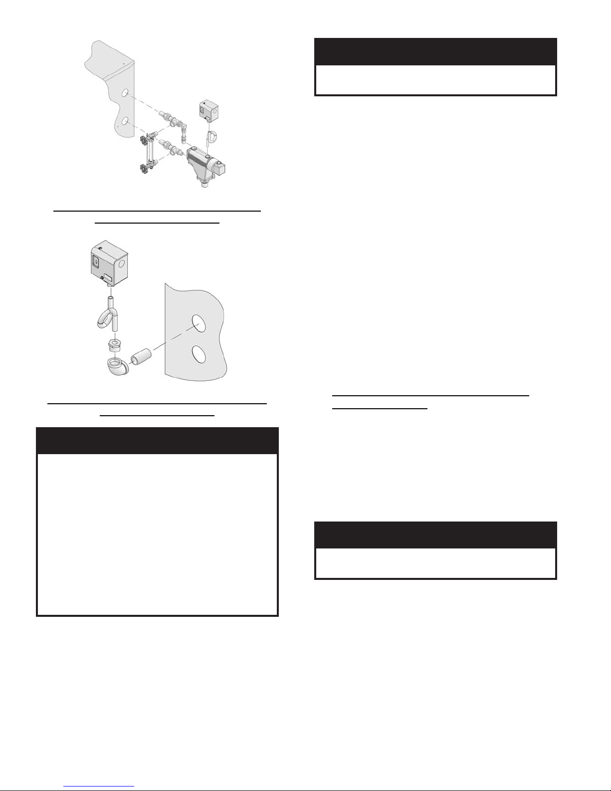
Figure 8: Float-Type Low Water Cut-Off and
Pressure Limit Installation
Figure 9: Pressure Limit Installation for Probe
LWCO Equipped Boilers
ECITON
oD.ebutdelaes
ton
.efillufesustifodneehtta
rucrem
.hsartehtnitimildlo
.ebutdelaesa
.2051-864-008-1
e. An L404F pressure limit does not require
leveling.
7. On units with a heater opening, install the aquastat
controller well in the ½" NPT or ¾” NPT tapping in
tankless heater plate or cover plate. Slip the bulb of
the aquastat into the well and secure the control in
place with the set screw.
22
od,ebutdelaesaniy
ton
tnemeganametsawlacolruoytcatnoC
gnidragersnoitcurtsnirofytirohtua
GNINRAW
otnidetresniyllufebtsumblubtatsauqA
.lleweht
8. Connect the fi eld wiring to the pressure limit, the
LWCO, the R8239A Control Center/J-box and the
burner J-box or burner disconnect J-box.
If equipped with tankless heater, connect fi eld
wiring from the aquastat control to the R8239A
Control Center transformer terminals or oil burner
primary control's "T-T" terminals.
Make the wiring connections as shown in Figures
19, 20 and 21.
NOTE:
• The R7184P Primary Control has pre-installed
"T-T" jumper resistor. To activate "T-T"
terminals, "T-T" jumper must be removed. To
remove, use side cutting pliers to cut jumper (see
Figure 28).
• Do not remove (cut) "T-T" jumper unless
wiring diagram indicates a direct connection
from thermostat and/or tankless heater aquastat
control to the oil burner primary control's "T-T"
terminals.
Refer to Paragraph S for details on use of burner
disconnect junction box provided with all
knockdown boiler builds.
O. INSTALL TRIM AND CONTROLS WITH
BECKETT BURNER. - Water Boilers Only (See
Figures 1A, 1B, 1C and 5).
1. Thread ½” NPT pipe plugs into gauge glass tappings
in the upper right side of front section.
aniyrucremniatnocstimiLerusserPA404L
hsartehtnitimilecalp
sniatnoctahttimilagnicalpersitimilsihtfI
ruoyecalp
2. Thread ¾” NPT pipe plug in probe low water cut off
tapping (just left of gauge glass tappings).
3. Thread combination pressure/temperature gauge into
¼” NPT tapping. Tighten with wrench applied to the
square shank of the gauge.
NOITUAC
sihtfolasopsidreporpehtdnagnilcycer
niyrucremgniniatnoctimildlonaforo,timil
ta.cnIllewyenoHllac,snoitseuqevahuoyfI
4. Screw drain valve into ¾" NPT side outlet of the
1½” NPT x 90° elbow (note - lower front section
tapping “G” is used for standard return on water
boilers).
5. If circulator (not supplied with boiler) is to be
mounted directly to 1½" NPT boiler return tapping
"G", use the piping arrangements outlined in steps a.
thru e. as follows: (see Figures 13A, 13B and 13C)
a. Thread 1½” NPT x 3” long nipple and 1½”
NPT x 90° elbow with ¾" NPT side outlet
into the return tapping and tighten with a pipe
wrench.
-esaceguagehtoterusserpylppatonoD
.sgnidaeretaruccaninitluseryamsiht

b. Thread 1½” NPT x 15” long nipple into the 1½"
NPT x 90° elbow and tighten with a pipe wrench.
c. Thread one of the circulator fl ange onto the
nipple and tighten with a pipe wrench. Position
fl ange so that the bolt slots are parallel to the
boiler front.
d. Place a circular fl ange gasket in the fl ange
groove on the circulator and mount the circulator
on the fl ange. Note that this is the return piping
and the fl ow arrow on the circulator should point
down Ð. Fasten circulator with 7/16” - 14 x 1½"
long cap screws and 7/16" - 14 nuts.
e. Fasten the second circulator fl ange and gasket to
the circulator.
6. Install relief valve, as shown in Figure 1A, 1B, and
1C, onto ¾” NPT x 8” nipple previously installed in
Paragraph H, No. 2, step b. Tighten with wrench.
Pipe discharge as shown in Figures 13A, 13B
and 13C. Installation of the relief valve must be
consistent with ANSI/ASME Boiler and Pressure
Vessel Code, Section IV.
GNINRAW
ebtsumgnipipegrahcsidevlavytefaS
folaitnetopetanimileotroolfraendepip
aeraynaniepiptonoD.snrubereves
llatsnitonoD.ruccodluocgnizeerferehw
.spacrosgulp,sevlavffo-tuhsyna
7. On units without a heater opening, install the well
into the ¾” NPT tapping "A" located on the front of
the boiler in the upper left corner. See Figures 1A
and 5. Tighten the well and insert the control’s bulb
into the well. Secure control to well with set screw.
GNINRAW
NOTE:
• Do not remove (cut) "T-T" jumper on R7184P
Primary Control for application 9a or 9b
above.
c. Refer to Paragraph S for details on use of burner
disconnect junction box provided with all
knockdown boiler builds.
P. INSTALL TRIM AND CONTROLS WITH
CARLIN 102CRD BURNER.
Follow instructions in Paragraph N, Steps 1 through 7.
Steam Boilers Only (see Figures 1D and 5).
8. Connect Field Wiring
a. Steam Boiler with Hydrolevel CG450 LWCO,
Carlin Burner.
Connect the fi eld wiring to the pressure limit, the
LWCO, R8239C Control Center and the burner
disconnect J-box or directly to burner J-box on
burners less disconnect harness (power cord).
If equipped with tankless heater, connect fi eld
wiring from the aquastat control to the R8239C
Control Center’s “R-G” terminals. Make the
wiring connections as shown in Figure 19A.
b. Steam Boiler with McDonnell & Miller
PS-801 or McDonnell & Miller 67 LWCO,
Carlin Burner.
Connect the fi eld wiring to the LWCO, the
pressure limit and the burner disconnect J-box.
If equipped with tankless heater, connect fi eld
wiring from the aquastat control to the oil burner
primary control’s “T-T” Terminals. Make the
wiring connections as shown in Figures 20A, and
21A.
c. Refer to Paragraph S for details on use of burner
disconnect junction box provided with all
knockdown boiler builds.
.lleweht
8. On units with a heater opening, install the well in
the ½" NPT or ¾” NPT tapping on the tankless
heater plate or cover plate. See Figures 1B, 1C and
5. Tighten the well and insert the control’s bulb into
the well. Secure control to well with set screw.
9. Connect Field Wiring.
a. Water boilers without tankless heater and with
front tankless heater. Connect the fi eld wiring
from the circulator to the aquastat control and
from the control to the burner disconnect J-box
or directly to the burner J-box. Make the wiring
connections as shown on Figures 22, 23A and
23D.
b. Water boilers with rear tankless heater. Connect
the fi eld wiring from a standard junction box
or burner disconnect J-box to the circulator,
aquastat control and burner. Make the wiring
connections as shown on Figure 23B.
otnidetresniyllufebtsumblubtatsauqA
Water boilers Only (see Figures 1A, 1B, 1C and 5).
Follow instructions in Paragraph O, Steps 1 through 7
9. Connect Field Wiring
a. Water boilers without tankless heater and with
front tankless heater. Connect the fi eld wiring
from the circulator to the aquastat control and
from the control to the burner disconnect J-box
or directly to oil burner primary control on
burners less disconnect harness (power cord).
Make the wiring connections as shown on
Figures 22A and 23B .
b. Water boilers with rear tankless heater. Connect
the fi eld wiring from a standard junction box
or burner disconnect J-box to the circulator,
aquastat control and burner. Make the wiring
connections as shown on Figure 23E.
c. Refer to Paragraph S for details on use of burner
disconnect junction box provided with all
knockdown boiler builds.
23

Q. INSTALL TRIM AND CONTROLS WITH
CARLIN ELITE EZ BURNER.
Follow instructions in Paragraph N, Steps 1 through 7.
Steam Boilers Only (see Figures 1D and 5).
8. Connect Field Wiring
a. Steam Boiler with Hydrolevel CG450 LWCO,
Carlin Burner.
Connect the fi eld wiring to the pressure limit, the
LWCO, R8239C Control Center and the burner
disconnect J-box or directly to burner J-box on
burners less disconnect harness (power cord).
If equipped with tankless heater, connect fi eld
wiring from the aquastat control to the R8239C
Control Center’s “R-G” terminals. Make the
wiring connections as shown in Figure 19.
b. Steam Boiler with McDonnell & Miller
PS-801 or McDonnell & Miller 67 LWCO,
Carlin Burner.
Connect the fi eld wiring to the pressure limit,
the R8239C Control Center, the LWCO and
the burner disconnect J-box. If equipped with
tankless heater, connect fi eld wiring from
the aquastat control to the oil burner primary
control’s “T-T” Terminals. Make the wiring
connections as shown in Figures 20 and 21.
c. Refer to Paragraph S for details on use of burner
disconnect junction box provided with all
knockdown boiler builds.
Water boilers Only (see Figures 1A, 1B, 1C and 5).
Follow instructions in Paragraph O, Steps 1 through 7.
9. Connect Field Wiring
a. Water boilers without tankless heater and with
front tankless heater. Connect the fi eld wiring
from the circulator to the aquastat control and
from the control to the burner disconnect J-box
or directly to oil burner primary control on
burners less disconnect harness (power cord).
Make the wiring connections as shown on
Figures 22 and 23A.
b. Water boilers with rear tankless heater. Connect
the fi eld wiring from a standard junction box
or burner disconnect J-box to the circulator,
aquastat control and burner. Make the wiring
connections as shown on Figure 23B.
c. Refer to Paragraph S for details on use of burner
disconnect junction box provided with all
knockdown boiler builds.
R. INSTALL TRIM AND CONTROLS WITH
RIELLO BURNER.
Follow instructions in Paragraph N, Steps 1 through 7.
Steam Boilers Only (see Figures 1D and 5).
8. Connect Field Wiring
a. Steam boiler with Hydrolevel CG450 or
McDonnell & Miller 67 LWCO, Riello Burner.
Connect the fi eld wiring to the pressure limit,
the LWCO, R8239C Control Center and the
burner disconnect J-box or directly to oil burner
primary control on burners less disconnect
harness (power cord). If equipped with tankless
heater, connect fi eld wiring from the aquastat
control to the R8239C Control Center’s “R-G”
terminals. Make the wiring connections as shown
in Figures 19 and 21.
b. Steam boiler with McDonnell & Miller PS-801
LWCO, Riello Burner.
Connect the fi led wiring to the pressure limit,
the R8239C Control Center, the LWCO and the
burner J-box. If equipped with tankless heater,
connect fi eld wiring from the aquastat control to
the R8239C Control Center’s “R-G” terminals.
Make the wiring connections as shown in Figure
20.
c. Refer to Paragraph S for details on use of burner
disconnect junction box provided with all
knockdown boiler builds.
Water Boilers Only (see Figures 1A, 1B, 1C and 5).
Follow instructions in Paragraph O, Steps 1 through 7.
9. Connect Field Wiring
a. Water boilers without tankless heater and with
front tankless heater. Connect the fi eld wiring from
the circulator to the aquastat control and from the
control to the burner disconnect J-box or directly
to oil burner primary control on burners less
disconnect harness (power cord). Make the wiring
connections as shown on Figures 22 and 23A.
b. Water boilers with rear tankless heater. Connect the
fi eld wiring from a standard junction box or burner
disconnect J-box to the circulator, aquastat control
and burner. Make the wiring connections as shown
on Figure 23B.
c. Refer to Paragraph S for details on use of burner
disconnect junction box provided with all
knockdown boiler builds.
S. BURNERS SUPPLIED BY BURNHAM utilize
a burner disconnect harness that is pre-wired into the
burner junction box and primary control. Packed in the
canopy carton is the mating burner disconnect junction
assembly and mounting hardware for use with these
burners.
If you are using a burner with the disconnect harness,
complete the following assembly instructions for
mounting the mating burner disconnect junction box,
see Figure 10.
24
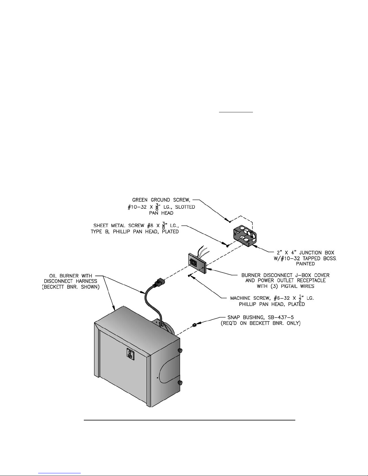
1. Remove (2) #6 x 1/2" lg. machine screws and J-box
cover from junction box.
2. Secure 2" x 4" junction box to jacket front panel
with (2) #8 x 3/8" lg. sheet metal screws using prepunched holes below tridicator or pressure gauge
tapping.
3. Complete the fi eld wiring phase of Paragraphs N &
O (Beckett), P (Carlin 102CRD), Q (Carlin Elite
EZ) or R (Riello) Install end of harness from low
water cut-off (LWCO), R8239A Control Center
or Aquastat Control into appropriate knockout of
burner disconnect junction box according to source,
refer to Figures 1A thru 1D.
4. Use wire nuts to connect wires from control or
power source to (3) pigtail wires connected to spade
terminals on rear of power outlet receptacle. Make
the connections as shown in appropriate wiring
diagram based on boiler confi guration, refer to
Figures 19 thru 23F.
5. Secure J-box cover to junction box with (2) #6 x ½"
lg. machine screws.
6. Insert mating end of burner disconnect harness
(power cord) into power outlet receptacle on J-box.
7. Install snap bushing into 7/16" diameter hole in
upper right corner of burner enclosure back plate
on all Beckett burners, see Figure 10. On certain
builds, 18/2 wire from L4006A Aquastat Control
mounted in rear heater will pass through this snap
bushing and connect to "T-T" terminals on primary
control, refer to Figures 20 and 21.
IMPORTANT: Remove (cut) jumper resistor on
R7184P Primary Control to activate "T-T" terminals
when making a direct connection from thermostat
and/or tankless heater aquastat control.
Figure 10: Burner Disconnect Junction Box with Power Outlet Receptacle
(Mated to Burners with Disconnect Harness)
25
SECTION III: PACKAGED BOILER ASSEMBLY
A. REMOVE CRATE.
1. Remove all fasteners at crate skid.
2. Lift outside container and remove all other inside
protective spacers and bracing. Remove draft
regulator box and miscellaneous trim bag containing
safety or relief valve, and pipe fi ttings.
B. REMOVE BOILER FROM SKID.
1. Boiler is secured to base with 4 bolts, 2 in front and
2 in rear of shipping skid, see Figure 11. Remove all
bolts.
Figure 11: Packaged Boiler Removal from Skid
2. Tilt boiler to right and to rear. Using right rear leg
as pivot, rotate boiler 90° in a clockwise direction,
and lower left side of boiler to fl oor. Tilt boiler and
remove crate skid. Care should be exercised to
prevent damage to jacket or burner.
NOITUAC
reliobpmubtonoD.reliobpordtonoD
.roolftsniagatekcaj
C. MOVE BOILER TO PERMANENT POSITION
by sliding or walking.
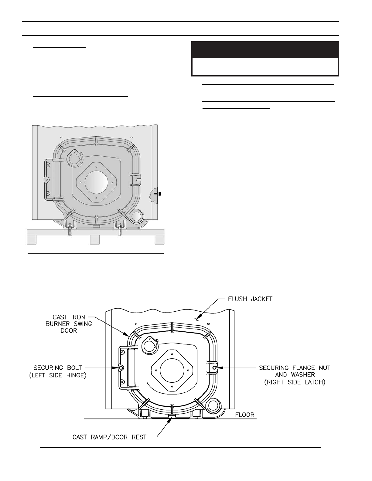
D. PROCEDURE TO OPEN, CLOSE AND SECURE
BURNER SWING DOOR with articulated hinge.
Throughout this manual you will be instructed to
open and close the burner swing door for various
reasons. There is a proper and improper method to
closing and securing the burner swing door after it
has been removed and re-installed for Field Assembly
(Knockdown Boiler) or opened for inspection, cleaning
or fi eld service.
1. TO OPEN BURNER SWING DOOR (see Figures
11A and 11B).
Step 1. Loosen and remove right side latching
hardware (5/16" fl ange nut and washer).
Step 2. Loosen and remove left side hinge hardware
(5/16" x 3-1/2" lg. hex head fl ange bolt).
Step 3. The duel pivot articulated hinge allows right
side of door to be pulled outward and rotated
to the left all in one motion. To do so, place
your right hand under burner air tube and lift up
slightly to help carry the weight of the door and
burner. Use your left hand to grasp the door's
left side hinge fl ange, pull outward to rotate the
hinge, this motion will move the door outward
and to the left approximately 3" (see Figure 11B,
Position 2).
Figure 11A: Partial Front View - Burner Swing Door Mounted to Boiler - Fully Closed and Secured
26
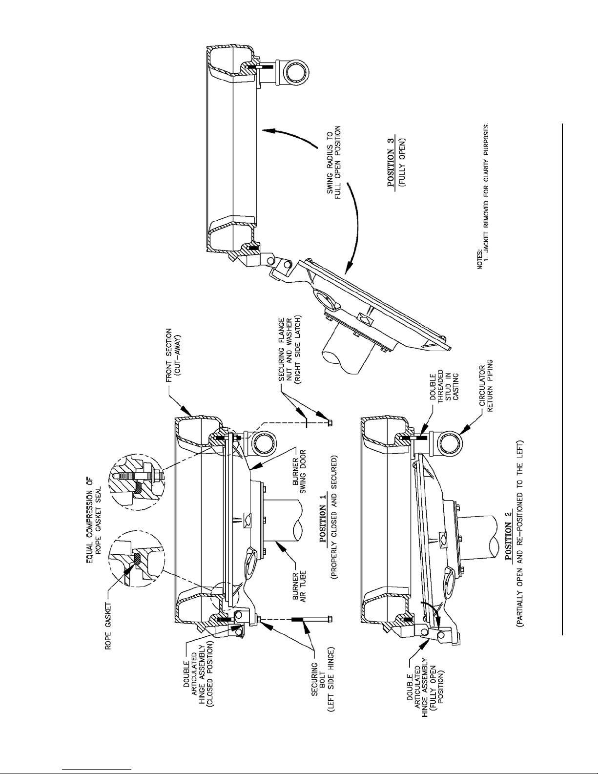
Figure 11B: Top View - Burner Swing Door Mounted to Cast Iron Block Assembly (Jacket Removed for Clarity)
27
Step 4. From this position the door can be swung
clear of the vertical circulator return piping to
provide full access to the combustion chamber
and burner head (see Figure 11B, Position 3).
2. Perform routine inspection, service or cleaning as
necessary.
3. To close Burner Swing Door (see Figures 11A and
11B):
Step 1. From the fully open position, rotate Burner
Swing Door toward the closed position. Make
sure that the articulated hinge is rotated to the
extreme left position to allow the door to clear
the vertical circulator return piping as shown in
Figure 11B, Position 2.
Step 2. Grasp the door's left side hinge fl ange
in your left hand and place your right hand
under the burner air tube to lift upward. Lift
the door up unto the built-in cast ramp/door
rest (protruding from the bottom of the front
section casting - see Figure 11A), while rotating
the articulated hinge and door to the right and
engaging the slot (on right side of door) unto the
5/16" stud protruding from the front section.
Step 3. Use one hand to help hold door in position
by lifting up on rear burner housing or applying
pressure directly to the door while re-installing
the securing hardware with your opposite hand.
Always install right side latching hardware
(5/16" fl ange nut and fl at washer) fi rst, then
install left side hinge hardware (5/16" x 31/2" lg. hex head fl ange bolt) second. Apply
additional pressure while hand tightening the
hardware as far as possible, then release the
pressure.
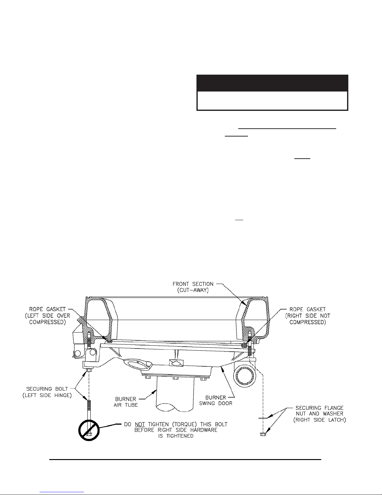
ECITON
ekamroodgniwsrenrubgnirucesnehW
.sedishtobnoyllauqeni-nwardsirooderus
Step 4. Use a hand wrench to tighten door hardware
and always start with the right side fl ange
nut fi rst. Use an alternating tightening method
from right side fl ange nut to left side fl ange
bolt to tighten door equally until sealed without
applying excessive torque. Never tighten left
side fl ange bolt fi rst or tighten either piece of
hardware 100% without using the alternating
tightening method described above.
Failure to follow the prescribed procedure could
cause thread damage to casting or a leak in the
door seal. If left side fl ange bolt is tightened
before right side fl ange nut, right side of door
can not be drawn-in to provide an air tight seal,
as shown in Figure 11C. Applying excessive
torque will only cause thread damage.
Figure 11C: Top View - Burner Swing Door Fully Closed but Not Properly Secured or Sealed
28

E. INSPECT COMBUSTION CHAMBER TARGET
WALL AND LINER, AND SWING DOOR
GASKET.
1. Open burner swing door using procedure previously
outlined in Paragraph D of this section.
2. Using a fl ashlight, inspect the rear target wall and
liner. The target wall should be rigidly secured to
the rear boiler section. The combustion chamber
liner should be evenly distributed in the boiler
chamber. If either is damaged, they must be
replaced.
3. Inspect ceramic rope located on the swing door.
The rope must be evenly distributed around the
perimeter of the door groove and cannot bunch or
overhang. There must not be a gap where the two
ends of the rope meet. Repair or replace if the rope
is damaged or if there is a gap between the ends.
F. INSPECT NOZZLE AND ELECTRODES /
CHANGE FIRING RATE FOR BECKETT
BURNERS. Refer to Section II, Paragraph J, No. 7,
steps b through o for nozzle installation, electrode and
head setting inspection.
Steam Boilers Only
Packaged V83 - V86 steam boilers are shipped with
the lower (standard) fi ring rate nozzle installed.
Packaged V87 - V89 boilers are provided with one
nozzle, installed in the burner, that provides the
same fi ring rate as the water boiler of the same size.
Inspect the installed nozzle and assure that the
nozzle is the correct size and type as specifi ed in
Table 6 of this manual.
Inspect and measure burner electrodes. Refer to
Figure 27 of this manual for the proper electrode
settings.
Close the burner swing door and securely seal the
door to the boiler front section by reinstalling the
hardware and securing the door using procedure
previously outlined in Paragraph D of this section.
Water Boilers Only
Packaged V8 water boilers are shipped with the
higher input oil nozzle installed in the burner.
A second oil nozzle for the lower (minimum) fi ring
rate is shipped loose for the V83 - V86 models,
attached to the burner. Select the proper oil
nozzle for the installation. The lower (minimum)
input nozzle will provide greater boiler effi ciency.
However, boiler output will be reduced. Refer to
Table 1B for ratings. If the higher rate is desired,
inspect the installed nozzle and assure that the
nozzle is the correct size and type as specifi ed in
Table 6 of this manual.
If the lower (minimum) input is desired, remove
the nozzle which was factory installed. Locate the
lower (minimum) fi ring rate nozzle that is supplied
loose. Confi rm the nozzle is the proper size and
type for the lower fi ring rate as specifi ed in Table
6 of this manual. Install the proper nozzle in the
burner nozzle adaptor.
G. INSPECT NOZZLE AND ELECTRODES
/ CHANGE FIRING RATE FOR CARLIN
102CRD BURNERS. Refer to Section II, Paragraph
K, No. 7, steps b through d for nozzle installation,
electrode and head setting inspection.
Follow instructions in Paragraphs A through E.
Steam or Water Boilers
Packaged V87 - V89 steam boilers are provided
with one nozzle, installed in the burner, that
provides the same fi ring rate as the water boiler of
the same size.
Inspect the installed nozzle and assure that the
nozzle is the correct size and type as specifi ed in
Table 6 of this manual.
H. INSPECT NOZZLE AND ELECTRODES /
CHANGE FIRING RATE FOR CARLIN ELITE
EZ BURNERS. Refer to Section II, Paragraph L, No.
7, steps a through c for nozzle installation, electrode
and head setting inspection.
Follow instructions in Section III, Paragraphs A through
E.
Steam Boilers Only
Packaged V83 - V86 steam boilers are shipped with
the lower (standard) fi ring rate nozzle installed.
Packaged V87 - V89 boilers are provided with one
nozzle, installed in the burner, that provides the
same fi ring rate as the water boiler of the same size.
Inspect the installed nozzle and assure that the
nozzle is the correct size and type as specifi ed in
Table 6.
Water Boilers Only
Packaged V8 water boilers are shipped with the
higher input oil nozzle installed in the burner.
A second oil nozzle for the lower (minimum) fi ring
rate is shipped loose for the V83 - V86 models,
attached to the burner. Select the proper oil
nozzle for the installation. The lower (minimum)
input nozzle will provide greater boiler effi ciency.
However, boiler output will be reduced. Refer
to Table 1B For fi ring rates. If the higher rate is
desired, inspect the installed nozzle and assure that
the nozzle is the correct size and type as specifi ed in
Table 6.
29

If the lower (minimum) input is desired, remove
the nozzle which was factory installed. Locate the
lower (minimum) fi ring rate nozzle that is supplied
loose. Confi rm the nozzle is the proper size and
type for the lower fi ring rate as specifi ed in Table
6. Install the proper nozzle in the burner nozzle
adaptor.
I. INSPECT NOZZLE AND ELECTRODES
/ CHANGE FIRING RATE FOR RIELLO
BURNERS. Refer to Section II, Paragraph M, No. 7,
steps a through g for nozzle installation, electrode and
head setting inspection.
Steam Boilers Only
Packaged V83 - V86 steam boilers are shipped with
the lower (standard) fi ring rate nozzle installed.
Packaged V87 - V89 boilers are provided with one
nozzle, installed in the burner, that provides the
same fi ring rate as the water boiler of the same size.
Inspect the installed nozzle and assure that the
nozzle is the correct size and type as specifi ed in
Table 6 of this supplement.
Water Boilers Only
Packaged V8 water boilers are shipped with the
higher input oil nozzle installed in the burner.
A second oil nozzle for the lower (minimum) fi ring
rate is shipped loose for the V83 - V86 models,
attached to the burner. Select the proper oil
nozzle for the installation. The lower (minimum)
input nozzle will provide greater boiler effi ciency.
However, boiler output will be reduced. Refer
to Table 1B for fi ring rates. If the higher rate is
desired, inspect the installed nozzle and assure that
the nozzle is the correct size and type as specifi ed in
Table 6.
If the lower (minimum) input is desired, remove
the nozzle which was factory installed. Locate the
lower (minimum) fi ring rate nozzle that is supplied
loose. Confi rm the nozzle is the proper size and
type for the lower fi ring rate as specifi ed in Table
6. Install the proper nozzle in the burner nozzle
adaptor.
GNINRAW
folaitnetopetanimileotroolfraendepipeb
aeraynaniepiptonoD.snrubereves
llatsnitonoD.ruccodluocgnizeerferehw
.spacrosgulp,sevlavffo-tuhsyna
K. PACKAGED BOILERS WITH PROBE STYLE
LWCO. Install Limit in Tapping "A" using ¾" NPT x
2" nipple, ¾" NPT elbow, ¾" NPT x ¼" NPT bushing,
and syphon included in trim bag. See Figure 9.
1. Do not tighten the limit by holding the case; apply a
wrench to the brass hex below the case.
2. Connect wiring harness from Low Water Cut-Off to
steam pressure limit.
3. Level an L404A pressure limit by carefully bending
the syphon until the limit's leveling indicator hangs
freely with its pointer directly over the index mark
inside the back of the case.
ECITON
aniyrucremniatnocstimiLerusserPA404L
oD.ebutdelaes
ton
.efillufesustifodneehtta
od,ebutdelaesaniyrucrem
ton
.hsartehtnitimildlo
gnidragersnoitcurtsnirofytirohtua
opsidreporpehtdnagnilcycer
.ebutdelaesa
.2051-864-008-1
4. An L404F pressure limit does not require leveling.
hsartehtnitimilecalp
sniatnoctahttimilagnicalpersitimilsihtfI
tnemeganametsawlacolruoytcatnoC
sihtfolas
tsumgnipipegrahcsidevlavfeilerroytefaS
ruoyecalp
niyrucremgniniatnoctimildlonaforo,timil
ta.cnIllewyenoHllac,snoitseuqevahuoyfI
J. INSTALL SAFETY OR RELIEF VALVE IN
TAPPING "M".
Use ¾" NPT x 8" nipple and/or ¾" NPT coupling
included in trim bag. Safety or Relief Valve must
be installed with spindle in vertical position. Pipe
discharge as shown in Figures 13A, 13B, 13C and
14. Installation of the safety or relief valve must be
consistent with ANSI/ASME Boiler and Pressure
Vessel Code, Section IV.
30
 Loading...