


INSTALLATION, OPERATING AND SERVICE INSTRUCTIONS FOR
Model MPC™ MULTI-PASS
COMMERCIAL CAST IRON BOILER
3050579
For service or repairs to boiler, call your heating contractor. When seeking information on boiler, provide Boiler Model Number and Serial Number as shown on Rating Label.
Boiler Model Number |
Boiler Serial Number |
Installation Date |
_ - MPC _ _ - _ _ _ _ |
|
|
|
|
|
Heating Contractor |
|
Type of Fuel |
|
|
|
Address |
|
Phone Number |
|
|
|
|
|
Commercial Boilers |
||
101786-01R5-11/10 |
www.burnhamcommercialcastiron.com |
||
|
|
Price - $5.00 |
|
EQUIPMENT CHECK LIST
NOTE: Only factory packaged and firetested units are eligible to bear the UL listing mark.
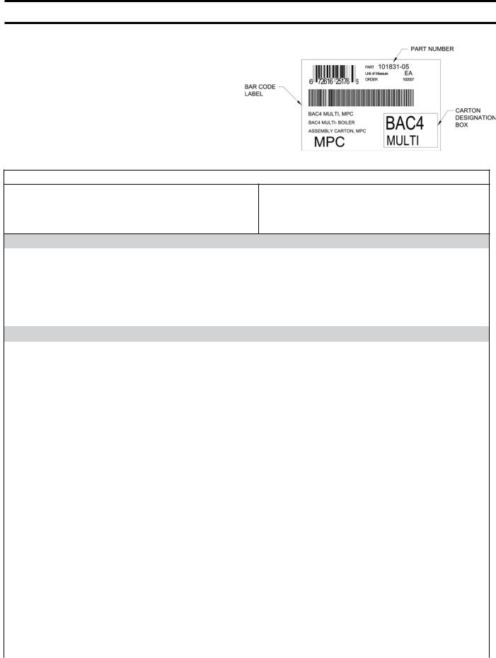
This Equipment Check List has been provided so that the Installer can determine if all parts have been provided for the boiler ordered. It covers standard equipment for Knockdown boilers, 4 thru 18 section models. Optional equipment ordered will be in addition to, or in lieu of, equipment shown below.
To simplify boiler assembly, instructions refer to carton |
|
designations located in box on Bar Code Labels, see Figure |
|
1a. When instructed, locate and open specified carton. |
|
Some cartons use all contents immediately and others use |
Figure 1a: Carton Identification |
parts throughout the assembly procedure until depleted. |
KNOCKDOWN BOILER - EQUIPMENT CHECK LIST
|
Carton |
|
|
Component Description |
Designation |
Part |
|
on Bar Code |
Number |
||
|
|||
|
Label |
|
|
|
|
|
Qty. Req’d. Per Boiler Size
4 Sect. |
5 Sect. |
6 Sect. |
7 Sect. |
8 Sect. |
9 Sect. |
10 Sect. |
11 Sect. |
12 Sect. |
13 Sect. |
14 Sect. |
15 Sect. |
16 Sect. |
17 Sect. |
18 Sect. |
|
|
|
|
|
|
|
|
|
|
|
|
|
|
|
Castings (Shipped Loose - Field Assembly)
MPC Common Castings & Parts Skid |
|
|
|
|
|
|
|
|
|
|
|
|
|
|
|
|
|
|
|||
(Includes Front Section, Rear Section, |
|
|
|
|
|
|
|
|
|
|
|
|
|
|
|
|
|
|
|||
Burner Swing Door Assembly, |
CP-S |
101829-01 |
1 |
|
1 |
1 |
1 |
1 |
1 |
1 |
1 |
1 |
1 |
1 |
1 |
1 |
1 |
1 |
|||
|
|
|
Rear Flue Collector and |
|
|
|
|
|
|
|
|
|
|
|
|
|
|
|
|
|
|
Miscellaneous Common Parts Carton) |
|
|
|
|
|
|
|
|
|
|
|
|
|
|
|
|
|
|
|||
|
|
Center Section - Machined |
|
|
|
|
|
|
|
|
|
|
|
|
|
|
|
|
|
|
|
[Quantity shown shipped on separate |
MPC-C |
100657-01 |
2 |
|
3 |
4 |
5 |
6 |
7 |
8 |
9 |
10 |
11 |
12 |
13 |
14 |
15 |
16 |
|||
|
skid(s), Maximum 6 per skid] |
|
|
|
|
|
|
|
|
|
|
|
|
|
|
|
|
|
|
||
|
|
|
|
|
Parts Cartons |
|
|
|
|
|
|
|
|
|
|
|
|
|
|
||
|
|
|
|
BAC4 |
101831-01 |
1 |
|
|
|
|
1 |
1 |
|
|
|
1 |
|
|
|
|
|
|
|
|
|
BAC5 |
101831-02 |
|
|
1 |
|
|
|
|
1 |
|
|
|
1 |
|
|
|
1 |
|
|
|
Boiler Assembly Cartons |
BAC6 |
101831-03 |
|
|
|
1 |
|
|
|
|
1 |
|
|
|
1 |
|
|
|
|
|
|
BAC7 |
101831-04 |
|
|
|
|
1 |
|
|
|
|
1 |
|
|
|
1 |
1 |
|
|
|
|
|
|
|
|
|
|
|
|
|
|
|
|
|
|
||||||
|
|
|
|
BAC4 Multi |
101831-05 |
|
|
|
|
|
1 |
|
|
|
|
1 |
1 |
1 |
1 |
|
2 |
|
|
|
|
BAC5 Multi |
101831-06 |
|
|
|
|
|
|
1 |
1 |
1 |
1 |
1 |
1 |
1 |
1 |
2 |
1 |
Supply & Return Manifold Carton |
S/RM CI |
103818-01 |
1 |
|
1 |
1 |
1 |
1 |
1 |
1 |
1 |
1 |
1 |
1 |
1 |
1 |
1 |
1 |
|||
|
|
|
|
RWMT 4 RC |
102804-04 |
1 |
|
|
|
|
|
|
|
|
|
|
|
|
|
|
|
|
|
|
|
RWMT 5 RC |
102804-05 |
|
|
1 |
|
|
|
|
|
|
|
|
|
|
|
|
|
|
|
|
|
RWMT 6 RC |
102804-06 |
|
|
|
1 |
|
|
|
|
|
|
|
|
|
|
|
|
|
|
|
|
RWMT 7 RC |
102804-07 |
|
|
|
|
1 |
|
|
|
|
|
|
|
|
|
|
|
|
|
|
|
RWMT 8 RC |
102804-08 |
|
|
|
|
|
1 |
|
|
|
|
|
|
|
|
|
|
|
|
|
|
RWMT 9 RC |
102804-09 |
|
|
|
|
|
|
1 |
|
|
|
|
|
|
|
|
|
Return Water Mixing Tube Cartons |
RWMT 10 RC |
102804-10 |
|
|
|
|
|
|
|
1 |
|
|
|
|
|
|
|
|
|||
RWMT 11 RC |
102804-11 |
|
|
|
|
|
|
|
|
1 |
|
|
|
|
|
|
|
||||
|
|
|
Restricted Clearance |
|
|
|
|
|
|
|
|
|
|
|
|
|
|
|
|||
|
|
|
RWMT 12 RC |
102804-12 |
|
|
|
|
|
|
|
|
|
1 |
|
|
|
|
|
|
|
|
|
|
|
|
|
|
|
|
|
|
|
|
|
|
|
|
|
|
|||
|
|
|
|
RWMT 13 RC |
102804-13 |
|
|
|
|
|
|
|
|
|
|
1 |
|
|
|
|
|
|
|
|
|
RWMT 14 RC |
102804-14 |
|
|
|
|
|
|
|
|
|
|
|
1 |
|
|
|
|
|
|
|
|
RWMT 15 RC |
102804-15 |
|
|
|
|
|
|
|
|
|
|
|
|
1 |
|
|
|
|
|
|
|
RWMT 16 RC |
102804-16 |
|
|
|
|
|
|
|
|
|
|
|
|
|
1 |
|
|
|
|
|
|
RWMT 17 RC |
102804-17 |
|
|
|
|
|
|
|
|
|
|
|
|
|
|
1 |
|
|
|
|
|
RWMT 18 RC |
102804-18 |
|
|
|
|
|
|
|
|
|
|
|
|
|
|
|
1 |
Jacket |
|
|
Jacket Frame (Front/Rear Rails) |
JF-1 |
101834-01 |
1 |
|
1 |
1 |
|
|
|
|
|
1 |
1 |
1 |
1 |
1 |
|
|
|
|
Jacket Frame |
|
|
|
|
|
|
|
|
|
|
|
|
|
|
|
|
|
|
|
Frame |
|
|
JF-2 |
101834-02 |
|
|
|
|
1 |
1 |
1 |
1 |
1 |
|
|
|
|
|
1 |
1 |
|
|
|
(Front/Center/Rear Rails) |
|
|
|
|
|
|
|
|
|
||||||||||
Cartons |
|
|
|
|
|
|
|
|
|
|
|
|
|
|
|
|
|
|
|
||
|
Jacket Frame (Center Rails) |
JF-3 |
101834-03 |
|
|
|
|
|
|
|
|
|
1 |
1 |
1 |
1 |
1 |
1 |
1 |
||
|
|
|
|
|
|
|
|
|
|
|
|
||||||||||
|
|
|
|
|
(Continued) |
|
|
|
|
|
|
|
|
|
|
|
|
|
|
||
|
|
|
|
|
|
|
|
|
|
|
|
|
|
|
|
|
|
|
|
|
|

KNOCKDOWN BOILER - EQUIPMENT CHECK LIST |
(Continued) |
|
|
|
|
|
|
||||||||||
|
Carton |
|
|
|
|
|
Qty. Req’d. Per Boiler Size |
|
|
|
|
||||||
Component Description |
Designation |
Part |
Sect.4 |
Sect.5 |
Sect.6 |
Sect.7 |
Sect.8 |
Sect.9 |
Sect.10 |
Sect.11 |
Sect.12 |
Sect.13 |
Sect.14 |
Sect.15 |
Sect.16 |
Sect.17 |
Sect.18 |
Code Label |
|
||||||||||||||||
|
on Bar |
Number |
|
|
|
|
|
|
|
|
|
|
|
|
|
|
|
|
|
|
|
|
|
|
|
|
|
|
|
|
|
|
|
|
|
Parts Cartons (Continued)
|
Complete Heat Exchanger |
CPHW 4 |
101835-04 |
1 |
|
|
|
|
|
|
|
|
|
|
|
|
|
|
|
CPHW 5 |
101835-05 |
|
1 |
|
|
|
|
|
|
|
|
|
|
|
|
|
|
|
Insulation Wrapper |
|
|
|
|
|
|
|
|
|
|
|
|
|
|
|||
|
CPHW 6 |
101835-06 |
|
|
1 |
|
|
|
|
|
|
|
|
|
|
|
|
|
|
|
|
|
|
|
|
|
|
|
|
|
|
|
|
|
|||
|
Front Heat Exchanger |
FTHW 1 |
101849-01 |
|
|
|
1 |
|
|
|
|
|
|
|
|
|
|
|
|
FTHW 2 |
101849-02 |
|
|
|
|
1 |
1 |
|
|
1 |
1 |
1 |
|
|
1 |
1 |
|
Heat Exchanger |
Insulation Wrapper |
|
|
|
|
|
|
|
|
|||||||||
FTHW 3 |
101849-03 |
|
|
|
|
|
|
1 |
1 |
|
|
|
1 |
1 |
|
|
||
|
|
|
|
|
|
|
|
|
|
|
|
|||||||
Insulation Bags |
|
|
|
|
|
|
|
|
|
|
|
|
||||||
Rear Heat Exchanger |
RRHW 1 |
101850-01 |
|
|
|
1 |
1 |
|
|
|
1 |
|
|
|
|
1 |
|
|
|
|
|
|
|
|
|
|
|
|
|
|
|||||||
|
RRHW 2 |
101850-02 |
|
|
|
|
|
1 |
1 |
|
|
1 |
1 |
1 |
|
|
1 |
|
|
Insulation Wrapper |
|
|
|
|
|
|
|
|
|
||||||||
|
RRHW 3 |
101850-03 |
|
|
|
|
|
|
|
1 |
|
|
|
|
1 |
|
|
|
|
|
|
|
|
|
|
|
|
|
|
|
|
|
|
||||
|
Center Heat Exchanger |
CTHW 1 |
101851-01 |
|
|
|
|
|
|
|
|
1 |
1 |
|
|
|
1 |
1 |
|
Insulation Wrapper |
CTHW 2 |
101851-02 |
|
|
|
|
|
|
|
|
|
|
1 |
1 |
1 |
1 |
1 |
|
Jacket Common Panels |
JC-1 |
101836-01 |
1 |
1 |
1 |
1 |
1 |
1 |
1 |
1 |
1 |
1 |
1 |
1 |
1 |
1 |
1 |
|
(Front and Rear) |
|||||||||||||||||
|
|
|
|
|
|
|
|
|
|
|
|
|
|
|
|
|
|
|
|
|
|
|
|
|
|
|
|
|
|
|
|
|
|
|
|
|
|
|
|
JC2- 4 |
101837-04 |
1 |
|
|
|
|
|
|
|
|
|
|
|
|
|
|
|
|
JC2- 5 |
101837-05 |
|
1 |
|
|
|
|
|
|
|
|
|
|
|
|
|
|
|
JC2- 6 |
101837-06 |
|
|
1 |
|
|
|
|
|
|
|
|
|
|
|
|
|
|
JC2- 7 |
101837-07 |
|
|
|
1 |
|
|
|
|
|
|
|
|
|
|
|
|
|
JC2- 8 |
101837-08 |
|
|
|
|
1 |
|
|
|
|
|
|
|
|
|
|
|
|
JC2- 9 |
101837-09 |
|
|
|
|
|
1 |
|
|
|
|
|
|
|
|
|
|
Jacket Uncommon Panels |
JC210 |
101837-10 |
|
|
|
|
|
|
1 |
|
|
|
|
|
|
|
|
|
(Outer Top Panels, Tie Bars, |
|
|
|
|
|
|
|
|
|
|
|
|
|
|
|
|
|
|
JC211 |
101837-11 |
|
|
|
|
|
|
|
1 |
|
|
|
|
|
|
|
|
|
Chaseway Channels & |
|
|
|
|
|
|
|
|
|
|
|
|
|
|
|||
|
JC212 |
101837-12 |
|
|
|
|
|
|
|
|
1 |
|
|
|
|
|
|
|
|
Internal Wiring Harness) |
|
|
|
|
|
|
|
|
|
|
|
|
|
|
|||
|
|
JC213 |
101837-13 |
|
|
|
|
|
|
|
|
|
1 |
|
|
|
|
|
|
|
JC214 |
101837-14 |
|
|
|
|
|
|
|
|
|
|
1 |
|
|
|
|
|
|
JC215 |
101837-15 |
|
|
|
|
|
|
|
|
|
|
|
1 |
|
|
|
Jacket Panel |
|
JC216 |
101837-16 |
|
|
|
|
|
|
|
|
|
|
|
|
1 |
|
|
Cartons |
|
|
|
|
|
|
|
|
|
|
|
|
|
|
|
|
|
|
|
JC217 |
101837-17 |
|
|
|
|
|
|
|
|
|
|
|
|
|
1 |
|
|
(4 Cartons |
|
|
|
|
|
|
|
|
|
|
|
|
|
|
|
|||
|
JC218 |
101837-18 |
|
|
|
|
|
|
|
|
|
|
|
|
|
|
1 |
|
Required per |
|
|
|
|
|
|
|
|
|
|
|
|
|
|
|
|||
Boiler) |
|
JC3- 4 |
101838-04 |
1 |
|
|
|
|
|
|
|
|
|
|
|
|
|
|
|
|
JC3- 5 |
101838-05 |
|
1 |
|
|
|
|
|
|
|
|
|
|
|
|
|
|
|
JC3- 6 |
101838-06 |
|
|
1 |
|
|
|
|
|
|
|
|
|
|
|
|
|
|
|
|
|
|
|
|
|
|
|
|
|
|
|
|
|
|
|
|
|
JC3- 7 |
101838-07 |
|
|
|
1 |
|
|
|
|
|
|
|
|
|
|
|
|
|
JC3- 8 |
101838-08 |
|
|
|
|
1 |
|
|
|
|
|
|
|
|
|
|
|
|
JC3- 9 |
101838-09 |
|
|
|
|
|
1 |
|
|
|
|
|
|
|
|
|
|
Jacket Uncommon Top |
JC310 |
101838-10 |
|
|
|
|
|
|
1 |
|
|
|
|
|
|
|
|
|
JC311 |
101838-11 |
|
|
|
|
|
|
|
1 |
|
|
|
|
|
|
|
|
|
Panels Cartons |
|
|
|
|
|
|
|
|
|
|
|
|
|
|
|||
|
|
JC312 |
101838-12 |
|
|
|
|
|
|
|
|
1 |
|
|
|
|
|
|
|
|
JC313 |
101838-13 |
|
|
|
|
|
|
|
|
|
1 |
|
|
|
|
|
|
|
JC314 |
101838-14 |
|
|
|
|
|
|
|
|
|
|
1 |
|
|
|
|
|
|
|
|
|
|
|
|
|
|
|
|
|
|
|
|
|
|
|
|
|
JC315 |
101838-15 |
|
|
|
|
|
|
|
|
|
|
|
1 |
|
|
|
|
|
JC316 |
101838-16 |
|
|
|
|
|
|
|
|
|
|
|
|
1 |
|
|
|
|
JC317 |
101838-17 |
|
|
|
|
|
|
|
|
|
|
|
|
|
1 |
|
|
|
|
|
|
|
|
|
|
|
|
|
|
|
|
|
|
|
|
|
|
JC318 |
101838-18 |
|
|
|
|
|
|
|
|
|
|
|
|
|
|
1 |
(Continued)
|
KNOCKDOWN BOILER - EQUIPMENT CHECK LIST |
|
(Continued) |
|
|
|
|
|
|
|
||||||||||
|
|
|
Carton |
|
|
|
|
|
Qty. Req’d. Per Boiler Size |
|
|
|
||||||||
Component Description |
|
Designation |
Part |
4 Sect. |
5 Sect. |
6 Sect. |
7 Sect. |
|
8 Sect. |
9 Sect. |
10 Sect. |
11 Sect. |
12 Sect. |
13 Sect. |
14 Sect. |
15 Sect. |
16 Sect. |
17 Sect. |
18 Sect. |
|
|
on Bar |
Number |
|
|||||||||||||||||
|
|
|
|
|||||||||||||||||
|
|
|
Code Label |
|
|
|||||||||||||||
|
|
|
|
|
|
|
|
|
|
|
|
|
|
|
|
|
|
|
|
|
|
|
Parts Cartons (Continued) |
|
|
|
|
|
|
|
|
|
|
|
|
|
|
||||
|
|
|
JC4- 4 |
101839-04 |
1 |
|
|
|
|
|
|
|
|
|
|
|
|
|
|
|
|
|
|
JC4- 5 |
101839-05 |
|
1 |
|
|
|
|
|
|
|
|
|
|
|
|
|
|
|
|
|
JC4- 6 |
101839-06 |
|
|
1 |
|
|
|
|
|
|
|
|
|
|
|
|
|
|
|
|
JC4- 7 |
101839-07 |
|
|
|
1 |
|
|
|
|
|
|
|
|
|
|
|
|
|
|
|
JC4- 8 |
101839-08 |
|
|
|
|
|
1 |
|
|
|
|
|
|
|
|
|
|
(Continued) |
|
|
JC4- 9 |
101839-09 |
|
|
|
|
|
|
1 |
|
|
|
|
|
|
|
|
|
|
Jacket Uncommon Side |
|
JC410 |
101839-10 |
|
|
|
|
|
|
|
1 |
|
|
|
|
|
|
|
|
|
|
JC411 |
101839-11 |
|
|
|
|
|
|
|
|
1 |
|
|
|
|
|
|
|
|
Jacket Panel Cartons |
Panel Cartons |
|
|
|
|
|
|
|
|
|
|
|
|
|
|
|
|
|||
|
JC412 |
101839-12 |
|
|
|
|
|
|
|
|
|
1 |
|
|
|
|
|
|
||
(4 Cartons Required |
|
|
|
|
|
|
|
|
|
|
|
|
|
|
|
|
|
|||
per Boiler) |
|
|
JC413 |
101839-13 |
|
|
|
|
|
|
|
|
|
|
1 |
|
|
|
|
|
|
|
|
|
|
|
|
|
|
|
|
|
|
|
|
|
|
|
|||
|
|
|
JC414 |
101839-14 |
|
|
|
|
|
|
|
|
|
|
|
1 |
|
|
|
|
|
|
|
JC415 |
101839-15 |
|
|
|
|
|
|
|
|
|
|
|
|
1 |
|
|
|
|
|
|
JC416 |
101839-16 |
|
|
|
|
|
|
|
|
|
|
|
|
|
1 |
|
|
|
|
|
JC417 |
101839-17 |
|
|
|
|
|
|
|
|
|
|
|
|
|
|
1 |
|
|
|
|
JC418 |
101839-18 |
|
|
|
|
|
|
|
|
|
|
|
|
|
|
|
1 |
|
|
|
2FB-18 |
101840-01 |
1 |
|
|
|
|
|
|
|
|
|
|
|
|
|
|
|
|
|
|
2FB-24 |
101840-02 |
|
1 |
|
|
|
|
|
|
|
|
|
|
|
|
|
|
|
|
|
2FB-31 |
101840-03 |
|
|
1 |
|
|
|
|
|
|
|
|
|
|
|
|
|
|
Second Pass Flueway |
|
2FB-38 |
101840-04 |
|
|
|
1 |
|
|
|
|
|
|
|
|
|
|
|
|
|
|
2FB-45 |
101840-05 |
|
|
|
|
|
1 |
|
|
|
|
|
|
|
|
|
|
|
|
Baffle Cartons |
|
|
|
|
|
|
|
|
|
|
|
|
|
|
|
|
|||
|
(Stainless Steel) |
|
2FB-51 |
101840-06 |
|
|
|
|
|
|
1 |
|
|
|
|
|
|
|
|
|
Flueway Baffle Cartons |
|
|
2FB-58 |
101840-07 |
|
|
|
|
|
|
|
1 |
1 |
|
|
|
|
|
|
1 |
|
|
|
|
|
|
|
|
|
|
|
|
|
|
|
|
|||||
|
|
|
2FB-65 |
101840-08 |
|
|
|
|
|
|
|
|
|
|
|
|
|
1 |
1 |
|
|
|
|
2FB72 |
101840-09 |
|
|
|
|
|
|
|
|
|
1 |
|
|
1 |
|
|
|
|
|
|
2FB78 |
101840-10 |
|
|
|
|
|
|
|
|
|
|
1 |
1 |
|
|
|
|
|
Third Pass Flueway |
|
|
|
|
|
|
|
|
|
|
|
|
|
|
|
|
|
|
|
|
Baffle Carton |
|
3FB |
101852-01 |
1 |
1 |
1 |
1 |
|
1 |
1 |
1 |
1 |
|
|
|
|
|
|
|
|
(Cold Rolled Steel) |
|
|
|
|
|
|
|
|
|
|
|
|
|
|
|
|
|
|
|
|
|
|
WT30-A |
101841-01 |
1 |
1 |
1 |
|
|
|
|
|
|
|
|
|
|
|
|
|
|
30 PSI Water Trim |
|
WT30-B |
101841-02 |
|
|
|
1 |
|
1 |
1 |
|
|
|
|
|
|
|
|
|
|
& Control Cartons |
|
WT30-C |
101841-03 |
|
|
|
|
|
|
|
1 |
1 |
1 |
1 |
1 |
1 |
1 |
|
|
Water Trim and |
|
|
WT30-D |
101841-04 |
|
|
|
|
|
|
|
|
|
|
|
|
|
|
1 |
1 |
|
|
WT50-A |
101853-01 |
1 |
1 |
1 |
1 |
|
1 |
1 |
|
|
|
|
|
|
|
|
|
|
Control Cartons |
50 PSI Water Trim |
|
|
|
|
|
|
|
|
|
|
|
||||||||
|
WT50-B |
101853-02 |
|
|
|
|
|
|
|
1 |
1 |
1 |
1 |
|
|
|
|
|
||
|
|
|
|
|
|
|
|
|
|
|
|
|
|
|||||||
|
& Control Cartons |
|
|
|
|
|
|
|
|
|
|
|
|
|
||||||
|
|
WT50-C |
101853-03 |
|
|
|
|
|
|
|
|
|
|
|
1 |
1 |
1 |
1 |
1 |
|
|
|
|
|
|
|
|
|
|
|
|
|
|
|
|||||||
|
|
|
|
|
|
|
|
|
|
|
|
|
|
|
|
|
|
|
|
|
|
80 PSI Water Trim |
|
WT80-A |
101854-01 |
1 |
1 |
1 |
1 |
|
1 |
1 |
1 |
1 |
1 |
|
|
|
|
|
|
|
& Control Cartons |
|
WT80-B |
101854-02 |
|
|
|
|
|
|
|
|
|
|
1 |
1 |
1 |
1 |
1 |
1 |
Flue Outlet Damper Carton - 7” |
|
FODC7 |
102473-01 |
1 |
1 |
|
|
|
|
|
|
|
|
|
|
|
|
|
|
|
Flue Outlet Damper Carton - 8” |
|
FODC8 |
102473-02 |
|
|
1 |
1 |
|
1 |
|
|
|
|
|
|
|
|
|
|
|
Flue Outlet Damper Carton - 10” |
|
FODC10 |
102473-03 |
|
|
|
|
|
|
1 |
1 |
1 |
|
|
|
|
|
|
|
|
Flue Outlet Damper Carton - 12” |
|
FODC12 |
102473-04 |
|
|
|
|
|
|
|
|
|
1 |
1 |
1 |
1 |
1 |
1 |
1 |
|
INSPECT SHIPMENT carefully for any signs of damage. All equipment is carefully manufactured, inspected and packed.
Our responsibility ceases upon delivery of Boiler to carrier in good condition. Any claims for damage or shortage in shipment must be filed immediately against the carrier by the consignee. No claims for variances or shortages will be allowed by Boiler Manufacturer, unless presented within thirty (30) days after receipt of equipment.

IMPORTANT INFORMATION -
READ and save these instructions for reference
All boilers must be installed in accordance with National, State and Local Plumbing, Heating and Electrical Codes and the regulations of the serving utilities. These Codes and Regulations may differ from this instruction manual. Authorities having jurisdiction should be consulted before installations are made.
In all cases, reference should be made to the following Standards:
USA BOILERS
A.Current Edition of American National Standard ANSI/NFPA 31, “Installation of Oil Burning Equipment”, for recommended installation practices.
B.Current Edition of National Fuel Gas Code, NFPA 54/ANSI Z223.1.
C.Current Edition of American National Standard ANSI/NFPA 211, “Chimneys, Fireplaces, Vents, and Solid Fuel Burning Appliances”, for venting requirements.
D.Current Edition of American Society of Mechanical Engineers ASME CSD-1, “Controls and Safety Devices forAutomatically Fired Boilers”, for assembly and operations of controls and safety devices.
E.All wiring on boilers installed in the USA shall be made in accordance with the National Electrical Code and/or Local Regulations.
CANADIAN BOILERS
A.Current Edition of Canadian Standards Association CSA B139, “Installation Code for Oil Burning Equipment”, for recommended Installation Practices.
B.The equipment shall be installed in accordance with the current Installation Code for Gas Burning Appliances and Equipment, CSA B149, and applicable Provincial Regulations for the class; which should be carefully followed in all cases.
Authorities having jurisdiction should be consulted before installations are made.
C.All wiring on boilers installed in Canada shall be made in accordance with the Canadian Electrical Code and/or Local Regulations.
DANGER
Indicates an imminently hazardous situation which, if not avoided, will result in death, serious injury or substantial property damage.
CAUTION
Indicates a potentially hazardous situation which, if not avoided, may result in moderate or minor injury or property damage.
WARNING
Indicates a potentially hazardous situation which, if not avoided, could result in death, serious injury or substantial property damage.
NOTICE
Indicates special instructions on installation, operation, or maintenance which are important but not related to personal injury hazards.
NOTICE
This boiler has a limited warranty, a copy of which is printed on the back of this manual.
It is the responsibility of the installing contractor to see that all controls are correctly installed and are operating properly when the installation is complete. The warranty for this boiler is valid only if the boiler has been installed, maintained and operated in accordance with these instructions.

DANGER
DO NOT store or use gasoline or other flammable vapors or liquids in the vicinity of this or any other appliance.
WARNING
Improper installation, adjustment, alteration, service or maintenance can cause property damage, personal injury or loss of life. Failure to follow all instructions in the proper order can cause personal injury or death. Read and understand all instructions, including all those contained in component manufacturers manuals which are provided with the appliance before installing, starting-up, operating, maintaining or servicing this appliance. Keep this manual and literature in legible condition and posted near appliance for reference by owner and service technician.
This boiler requires regular maintenance and service to operate safely. Follow the instructions contained in this manual.
Installation,maintenance,andservicemustbeperformedonlybyanexperienced,skilledandknowledgeable installer or service agency.
All heating systems should be designed by competent contractors and only persons knowledgeable in the layout and installation of hydronic heating systems should attempt installation of any boiler.
It is the responsibility of the installing contractor to see that all controls are correctly installed and are operating properly when the installation is completed.
Installation is not complete unless a pressure relief valve is installed into the specified tapping on the supply manifold located on top and at rear of appliance - See Section III, Paragraph R, Item 3 of this manual for details.
All boiler builds, except boilers bearing the ULLabel, are suitable for installation on combustible flooring. Do not install boiler on carpeting. Do not operate on floors where heat affected material is below.
Do not tamper with or alter the boiler or controls. Retain your contractor or a competent serviceman to assure that the unit is properly adjusted and maintained.
Clean boiler at least once a year - preferably at the start of the heating season to remove soot and scale. The inside of the combustion chamber should also be cleaned and inspected at the same time.
Have Burner and Controls checked at least once a year or as may be necessitated. Do not operate unit with jumpered or absent controls or safety devices. Do not operate unit if any control, switch, component, or device has been subject to water.
This boiler is designed to operate with lower return water temperatures and avoid thermal shock and accumulation of condensate if operated per the following criteria:
•Minimum Return Water Temperature = 80°F
•Maximum Delta T Between Boiler Supply and Return = 80°F
•Minimum Supply Water Temperature = 130°F
Continued operation beyond these limitations will result in sustained condensing within the combustion chamber and potentially reduce boiler longevity and may result in premature boiler failure through thermal shock.

WARNING
Appliance materials of construction, products of combustion and the fuel contain alumina, silica, heavy metals, carbon monoxide, nitrogen oxides, aldehydes and/or other toxic or harmful substances which can cause death or serious injury and which are known to the state of California to cause cancer, birth defectsandotherreproductiveharm. Alwaysusepropersafetyclothing,respiratorsandequipmentwhen servicing or working nearby the appliance.
This boiler contains very hot water under high pressure. Do not unscrew any pipe fittings nor attempt to disconnect any components of this boiler without positively assuring the water is cool and has no pressure. Always wear protective clothing and equipment when installing, starting up or servicing this boiler to prevent scald injuries. Do not rely on the pressure and temperature gauges to determine the temperature and pressure of the boiler. This boiler contains components which become very hot when the boiler is operating. Do not touch any components unless they are cool.
This appliance must be properly vented and connected to an approved vent system in good condition. Do not operate boiler with the absence of an approved vent system.
This boiler needs fresh air for safe operation and must be installed so there are provisions for adequate combustion and ventilation air.
The interior of the venting and air intake systems must be inspected and cleaned before the start of the heating season and should be inspected periodically throughout the heating season for any obstructions. Clean and unobstructed venting and air intake systems are necessary to allow noxious fumes that could cause injury or loss of life to vent safely and will contribute toward maintaining the boiler’s efficiency.
This boiler is supplied with controls which may cause the boiler to shut down and not re-start without service. If damage due to frozen pipes is a possibility, the heating system should not be left unattended in cold weather; or appropriate safeguards and alarms should be installed on the heating system to prevent damage if the boiler is inoperative.
This boiler is designed to burn No. 2 fuel oil only. Do not use gasoline, crankcase drainings, or any oil containing gasoline. Never burn garbage or paper in this boiler. Do not convert to any solid fuel (i.e. wood, coal). Do not convert to any gaseous fuel (i.e. natural gas, LP). All flammable debris, rags, paper, wood scraps, etc., should be kept clear of the boiler at all times. Keep the boiler area clean and free of fire hazards.
Always keep the oil supply valve shut off if the burner is shut down for an extended period of time.
Probe and float type low water cutoff devices require annual inspection and maintenance. Refer to instructions in Section VI, Paragraph C for inspection and cleaning instructions.
NOTICE
Model MPC cast iron boilers are designed, built, marked and tested in accordance with the ASME Boiler and Pressure Vessel Code, Section IV, Heating Boilers. An ASME Data Label is factory applied to each MPC jacket, which indicates the boiler Maximum Allowable Working Pressure (MAWP). Each cast iron section is permanently marked with the MAWP listed on the boiler’s ASME Data Label. This value for the MPC is as follows:
MAWP, Water (USA and Canada) - 80 PSI
It is common and acceptable practice to install these boilers in lower pressure systems, below the boiler MAWP. Therefore, Burnham offers safety relief valves set at or below the MAWP of the boiler. See Page 12 for available safety relief valve set pressures.

Table of Contents |
|
SECTION I - GENERAL INFORMATION |
|
Dimensional Information.................................................................................................................. |
10 |
Ratings/Data....................................................................................................................................... |
12 |
Locating the Unit ............................................................................................................................... |
13 |
Air Supply/Venting............................................................................................................................. |
14 |
SECTION II - CAST IRON BLOCK ASSEMBLY INSTRUCTIONS (Knockdown Boiler) |
|
Knockdown Boiler w/ Factory Assembled Section......................................................................... |
17 |
Assembly of Sections, Manual Draw-up ......................................................................................... |
18 |
Assembly of Sections, Hydraulic Draw-up ..................................................................................... |
23 |
Hydrostatic Test ................................................................................................................................ |
24 |
SECTION III - BOILER ASSEMBLY INSTRUCTIONS (Knockdown Boiler) |
|
Install Common Parts to Block (Hinge Hardware, Flue Collector, Clean-out Covers, Etc.) ....... |
25 |
Install Supply and Return Manifolds ............................................................................................... |
27 |
Install Return Water Mixing Tube...................................................................................................... |
27 |
Install Jacket Support Frame to Block............................................................................................. |
30 |
Install Heat Exchanger Insulation..................................................................................................... |
37 |
Install Internal Wiring Harness Components ................................................................................. |
38 |
Install Jacket Top Corner Panels ..................................................................................................... |
43 |
Install Jacket Front and Rear Panels .............................................................................................. |
44 |
Install Jacket Top and Side Panels .................................................................................................. |
45 |
Install Burner Swing Door (BSD) ..................................................................................................... |
47 |
Install 2nd and 3rd Pass Flueway Baffles........................................................................................... |
49 |
Procedure to Close and Secure Burner Swing Door...................................................................... |
50 |
Install Burner Adapter Plate and Mount Burner (Burner Specific)................................................ |
50 |
Connecting Internal Wiring Harness to Burner Controls............................................................... |
51 |
Install Standard Water Trim and Control.......................................................................................... |
52 |
Install Optional Controls: |
|
• Probe LWCO............................................................................................................................. |
54 |
• High Limit Control w/ Manual Reset....................................................................................... |
54 |
• Low Fire Hold Control.............................................................................................................. |
54 |
• Low / High / Low Control or Modulating Control................................................................... |
55 |
Install Flue Outlet Damper Assembly............................................................................................... |
56 |
Install Optional Burner Swing Door Cover Split Jacket Panels..................................................... |
57 |
SECTION IV - INSTALLATION INSTRUCTIONS |
|
Packaged Boiler - Shipping Information.......................................................................................... |
58 |
Boiler Piping - Heating Applications................................................................................................ |
58 |
Boiler Piping - Domestic Hot Water.................................................................................................. |
64 |
Relief Valve Piping............................................................................................................................. |
64 |
Electric Wiring.................................................................................................................................... |
64 |
SECTION V - OPERATING INSTRUCTIONS |
|
Filling System..................................................................................................................................... |
65 |
Adjusting Controls............................................................................................................................. |
65 |
Adjusting Burner................................................................................................................................ |
65 |
Test Controls...................................................................................................................................... |
66 |
Initial Cleaning, Water Boilers........................................................................................................... |
66 |
Frequent Water Addition................................................................................................................... |
67 |
Oxygen Corrosion.............................................................................................................................. |
67 |

Table of Contents (continued)
SECTION VI - SERVICE INSTRUCTIONS |
|
Cleaning Boiler Heating Surfaces.................................................................................................... |
68 |
Maintenance of Low Water Cutoff Devices...................................................................................... |
69 |
Checking Burner & Controls............................................................................................................. |
70 |
Lubrication.......................................................................................................................................... |
70 |
General Maintenance Considerations.............................................................................................. |
70 |
Attention to Boiler While Not in Operation...................................................................................... |
70 |
Recommended Periodic Testing....................................................................................................... |
71 |
SECTION VII - BURNER SPECIFICATIONS |
|
Beckett Burners (Tables XIIIa and XIIIb).......................................................................................... |
73 |
Power Flame Burners (Tables XIVa, XIVb and XIVc)....................................................................... |
74 |
SECTION VIII - REPAIR PARTS |
|
Regional Office Directory.................................................................................................................. |
76 |
Cast Iron Section Assembly.............................................................................................................. |
76 |
Common Bare Boiler Components.................................................................................................. |
78 |
Front & Center Section Frame Rail Assembly................................................................................. |
82 |
Rear Section Frame Rail Assembly.................................................................................................. |
84 |
Return Water Mixing Tube Assembly............................................................................................... |
86 |
Heat Exchanger Insulation Wrapper................................................................................................ |
88 |
Internal Wiring Harness Components.............................................................................................. |
90 |
Jacket Panel Assembly...................................................................................................................... |
92 |
2nd and 3rd Pass Flueway Baffles....................................................................................................... |
96 |
Standard Water Trim and Controls................................................................................................... |
98 |
Optional Working Pressure Trim.................................................................................................... |
100 |
Optional Controls............................................................................................................................. |
102 |
APPENDIX A - LIST OF FIGURES................................................................................................................ |
104 |
APPENDIX B - LIST OF TABLES.................................................................................................................. |
107 |
WARRANTY................................................................................................................................ |
REAR COVER |

10
* Wiring harness shown in this location for illustration purposes - typically, wiring harness leads will exit jacket on same side as BSD hinges.
Figure 1b: Dimensional Information
SECTION I - GENERAL INFORMATION
Table I: Dimensional Information
|
Number |
|
* Burner Dimension B (Inches) |
Minimum Flue |
Vent (Flue Outlet |
Approx. Weight of |
Approx. |
||||
Boiler |
Dim. A |
Beckett |
Power Flame |
Baffle Installation |
Damper) |
Shipping |
|||||
of |
Sections - LBS. |
||||||||||
Model |
(Inches) |
|
|
|
|
Clearance Dim. C |
Connection Size |
Weight - LBS. |
|||
Sections |
CF |
CG |
C |
JR |
(Block Assy.) |
||||||
|
|
(Inches) |
Dim. D (Inches) |
(KD Boiler) |
|||||||
|
|
|
|
||||||||
|
|
|
|
|
|
|
|
|
|
|
|
MPC4 |
4 |
33-3/4 |
10-1/4 |
20-3/4 |
29-5/8 |
23 |
35 |
7” |
1875 |
2370 |
|
|
|
|
|
|
|
|
|
|
|
|
|
MPC5 |
5 |
40-1/2 |
12-1/4 |
21-3/4 |
29-5/8 |
23 |
35 |
7” |
2321 |
2821 |
|
|
|
|
|
|
|
|
|
|
|
|
|
MPC6 |
6 |
47-1/4 |
20-1/2 |
28-1/2 |
29-5/8 |
23 |
41 |
8” |
2767 |
3272 |
|
|
|
|
|
|
|
|
|
|
|
|
|
MPC7 |
7 |
54 |
20-1/2 |
28-1/2 |
29-5/8 |
23 |
48 |
8” |
3213 |
3733 |
|
|
|
|
|
|
|
|
|
|
|
|
|
MPC8 |
8 |
60-3/4 |
21 |
29 |
34-5/8 |
25-3/4 |
55 |
8” |
3659 |
4194 |
|
|
|
|
|
|
|
|
|
|
|
|
|
MPC9 |
9 |
67-1/2 |
21 |
29 |
34-5/8 |
25-3/4 |
61 |
10” |
4105 |
4655 |
|
|
|
|
|
|
|
|
|
|
|
|
|
MPC10 |
10 |
74-1/4 |
21 |
29 |
34-5/8 |
25-3/4 |
68 |
10” |
4551 |
5116 |
|
|
|
|
|
|
|
|
|
|
|
|
|
MPC11 |
11 |
81 |
22-1/2 |
29 |
34-5/8 |
25-3/4 |
68 |
10” |
4997 |
5577 |
|
|
|
|
|
|
|
|
|
|
|
|
|
MPC12 |
12 |
87-7/8 |
22-1/2 |
29-3/8 |
34-5/8 |
--- |
82 |
10” |
5443 |
6073 |
|
|
|
|
|
|
|
|
|
|
|
|
|
MPC13 |
13 |
94-5/8 |
22-1/2 |
29-3/8 |
34-5/8 |
--- |
88 |
12” |
5889 |
6544 |
|
|
|
|
|
|
|
|
|
|
|
|
|
MPC14 |
14 |
101-3/8 |
22-1/2 |
29-3/8 |
34-5/8 |
--- |
88 |
12” |
6335 |
7015 |
|
|
|
|
|
|
|
|
|
|
|
|
|
MPC15 |
15 |
108-1/8 |
22-1/2 |
29-3/8 |
39-1/2 |
--- |
82 |
12” |
6781 |
7486 |
|
|
|
|
|
|
|
|
|
|
|
|
|
MPC16 |
16 |
114-7/8 |
26-3/8 |
29-3/8 |
39-1/2 |
--- |
75 |
12” |
7227 |
7957 |
|
|
|
|
|
|
|
|
|
|
|
|
|
MPC17 |
17 |
121-5/8 |
26-3/8 |
29-3/8 |
39-1/2 |
--- |
75 |
12” |
7673 |
8438 |
|
|
|
|
|
|
|
|
|
|
|
|
|
MPC18 |
18 |
128-3/8 |
26-3/8 |
29-3/8 |
39-1/2 |
--- |
68 |
12” |
8119 |
8919 |
|
|
|
|
|
|
|
|
|
|
|
|
|
* Burner control panel configuration may change this dimension.
11

|
|
|
|
|
|
|
TABLE II: Ratings/Data |
|
|
|
|
|
||||
|
|
|
|
|
|
|
|
|
|
|
|
|
|
|
|
|
|
|
|
|
Model MPC™ Boilers |
|
|
|
|
|
|
|
|
|
|||
|
(1) |
|
|
(3) |
|
|
(2) |
|
|
|
|
|
(4) |
|
|
|
|
|
|
|
|
|
|
|
|
|
|
|
|
|
|
|
|
|
ModelBoiler |
HorsepowerBoiler |
(GPH)Oil |
(MBH)Oil |
(MBH)Gas |
OutputGross(MBH) |
I=B=RNetRating (MBH) |
Combustion |
|
SurfaceHeating Ft.)(Sq. |
FurnaceNetVolume Ft.)(Cu. |
inPressureFirebox Wtr.(InchesColumn) |
ContentWater (Gallons) |
WeightBoiler (LBS.)w/Water |
(FlueVentOutlet Damper)Dia. (Inches) |
|
|
%-Oil |
%-Gas |
|
|||||||||||||
|
|
|
Burner Input |
|
|
Efficiency |
|
|
|
|
|
|
|
|||
|
|
|
|
|
|
|
|
|
|
|
|
|
|
|
|
|
|
MPC4 |
12.7 |
3.55 |
497 |
500 |
424 |
369 |
89.0 |
86.3 |
|
75.0 |
7.1 |
0.10 |
63 |
2820 |
7 |
|
|
|
|
|
|
|
|
|
|
|
|
|
|
|
|
|
|
MPC5 |
19.5 |
5.50 |
770 |
773 |
652 |
567 |
88.8 |
86.1 |
|
95.3 |
9.1 |
0.19 |
78 |
3396 |
7 |
|
|
|
|
|
|
|
|
|
|
|
|
|
|
|
|
|
|
MPC6 |
25.0 |
7.10 |
994 |
995 |
837 |
728 |
88.7 |
86.0 |
|
115.5 |
11.0 |
0.28 |
93 |
3972 |
8 |
|
|
|
|
|
|
|
|
|
|
|
|
|
|
|
|
|
|
MPC7 |
30.6 |
8.70 |
1218 |
1216 |
1023 |
890 |
88.7 |
86.0 |
|
135.8 |
12.9 |
0.34 |
108 |
4558 |
8 |
|
|
|
|
|
|
|
|
|
|
|
|
|
|
|
|
|
|
MPC8 |
36.1 |
10.2 |
1428 |
1438 |
1209 |
1051 |
88.6 |
85.9 |
|
156.1 |
14.8 |
0.39 |
123 |
5144 |
8 |
|
|
|
|
|
|
|
|
|
|
|
|
|
|
|
|
|
|
MPC9 |
41.7 |
11.8 |
1652 |
1660 |
1395 |
1213 |
88.6 |
85.9 |
|
176.4 |
16.7 |
0.45 |
137 |
5721 |
10 |
|
|
|
|
|
|
|
|
|
|
|
|
|
|
|
|
|
|
MPC10 |
47.2 |
13.4 |
1876 |
1881 |
1580 |
1374 |
88.6 |
85.9 |
|
196.6 |
18.6 |
0.50 |
152 |
6307 |
10 |
|
|
|
|
|
|
|
|
|
|
|
|
|
|
|
|
|
|
MPC11 |
52.8 |
15.0 |
2100 |
2103 |
1766 |
1536 |
88.5 |
85.9 |
|
216.9 |
20.6 |
0.66 |
167 |
6893 |
10 |
|
|
|
|
|
|
|
|
|
|
|
|
|
|
|
|
|
|
MPC12 |
58.3 |
16.6 |
2324 |
2325 |
1951 |
1697 |
88.5 |
85.8 |
|
237.2 |
22.5 |
0.82 |
182 |
7489 |
12 |
|
|
|
|
|
|
|
|
|
|
|
|
|
|
|
|
|
|
MPC13 |
63.8 |
18.2 |
2548 |
2547 |
2137 |
1858 |
88.5 |
85.8 |
|
257.5 |
24.4 |
0.98 |
196 |
8077 |
12 |
|
|
|
|
|
|
|
|
|
|
|
|
|
|
|
|
|
|
MPC14 |
69.4 |
19.8 |
2772 |
2769 |
2322 |
2019 |
88.5 |
85.8 |
|
277.7 |
26.3 |
1.14 |
211 |
8673 |
12 |
|
|
|
|
|
|
|
|
|
|
|
|
|
|
|
|
|
|
MPC15 |
74.9 |
21.5 |
3010 |
2991 |
2508 |
2181 |
88.4 |
85.8 |
|
298.0 |
28.2 |
1.30 |
226 |
9269 |
12 |
|
|
|
|
|
|
|
|
|
|
|
|
|
|
|
|
|
|
MPC16 |
80.5 |
23.0 |
3220 |
3213 |
2694 |
2343 |
88.4 |
85.8 |
|
318.3 |
30.2 |
1.30 |
241 |
9865 |
12 |
|
|
|
|
|
|
|
|
|
|
|
|
|
|
|
|
|
|
MPC17 |
86.0 |
24.5 |
3430 |
3435 |
2880 |
2504 |
88.4 |
85.8 |
|
338.6 |
32.1 |
1.40 |
256 |
10470 |
12 |
|
|
|
|
|
|
|
|
|
|
|
|
|
|
|
|
|
|
MPC18 |
91.6 |
26.0 |
3640 |
3657 |
3065 |
2665 |
88.4 |
85.8 |
|
358.8 |
34.0 |
1.50 |
270 |
11068 |
12 |
|
|
|
|
|
|
|
|
|
|
|
|
|
|
|
|
|
(1)Suffix “N” indicates natural gas-fired, suffix “P” indicates LP gas-fired, “O” indicates oil-fired, “C” indicates combination natural gas/oil-fired, “D” indicates combination LP gas/oil-fired.
(2)I=B=R net ratings shown are based on 1.15 piping and pickup factor for water.
Consult manufacturer for installations having unusual piping and pickup requirements, such as intermittent system operation, extensive piping systems, etc.
(3)The I=B=R burner capacity in GPH is based on oil having a heat value of 140,000 BTU per gallon.
(4)Boiler ratings are based on 13.2% CO2 (oil) and 10.2% CO2 (natural gas) and +.10” water column pressure at boiler flue outlet.
Ratings shown above apply at altitudes up to 1000 feet on oil and 2000 feet on gas. For altitudes above those indicated, the ratings should be reduced at the rate of 4% for each 1000 feet above sea level.
Safety Relief Valve Set Pressure: Standard - 50 PSI; Optional - 30 PSI, 80 PSI
12

SECTION I - GENERAL INFORMATION (Continued)
A.INSPECT SHIPMENT carefully for any signs of damage.
1.ALL EQUIPMENT is carefully manufactured, inspected and packed. Our responsibility ceases upon delivery of crated Boiler to the carrier in good condition.
2.ANY CLAIMS for damage or shortage in shipment must be filed immediately against the carrier by the consignee. No claims for variances from,
or shortage in orders, will be allowed by the manufacturer unless presented within thirty (30) days after the receipt of goods.
B.LOCATE THE UNIT
NOTICE
Recommended clearance for service may be reduced to minimum clearance to combustible material. However, increased service and maintenance difficulty will result.
1.RECOMMENDED SERVICE CLEARANCE
-Locate the unit in the boiler room so as to provide ease of venting and adequate clearance for maintenance, serviceability, and installation of piping. Refer to Figure 1b and Table 1 for boiler dimensional data.
from Jacket Front Panel:
•Provide 54” service clearance for removal, maintenance, and servicing of burner and controls.
•Provide service clearance for removal of baffles to perform annual cleaning of
flueways, refer to Table I, Dimension “C”.
From Jacket Rear Panel:
•Provide a minimum service clearance from the boiler jacket for access to boiler supply and return piping, relief valve, drain valve, flue collector clean-out covers, vent piping and optional flue damper assembly. See
Table III.
Table III: Recommended Rear Service Clearance
Flue Outlet Size |
Combustible or Non-Combustible |
|
Surfaces |
||
|
||
|
|
|
7” Dia. |
36 |
|
8” Dia. |
36 |
|
10” Dia. |
36 |
|
12” Dia. |
36 |
From Jacket Left Side Panel:
•Provide clearance per Table I, Dimension ‘B’, for burner swing door (BSD), opened fully with burner mounted, otherwise 12” with burner removed.
•18” access clearance to service rear of boiler if right side clearance is less than 12”.
•12” minimum if right side clearance is 18” or larger to access and service rear of boiler.
From Jacket Right Side Panel:
•See Table I, Dimension ‘B’ if BSD is hinged to swing to right side with burner mounted, otherwise 12” minimum if left side clearance is 18” or larger to access and service rear of boiler.
From Jacket Top Panel:
•Provide a minimum clearance from the boiler jacket of 24”.
2.FOR MINIMUM CLEARANCES to combustible materials, See Table IV or Table V.
Table IV: Minimum Installation Clearances To
Combustible Materials (Inches) per
ANSI/NFPA 31 (Knockdown/Non-UL
Packaged Boiler)
|
|
|
C |
|
|
|
A |
B |
Chimney |
D |
E |
Boiler |
Above |
Front |
Connector |
Rear |
Sides |
|
|
|
|
|
|
MPC |
6 |
24 |
18 |
6 |
6 |
Note: See Table III for recommended service clearance to access rear of boiler.
NOTE 1: Listed clearances comply with American National Standard ANSI/NFPA 31, Installation of Oil Burning Equipment.
NOTE 2: MPC Series boilers can be installed in rooms with clearances from combustible material as listed above. Listed clearances cannot be reduced for alcove or closet installations.
NOTE 3: For reduced clearances to combustible material, protection must be provided as described in the above ANSI/NFPA 31 Standard.
13

Table V: Minimum Installation Clearances To
Combustible Materials (Inches) per
UL726 (Packaged / Firetested Boiler)
|
|
|
C |
|
|
|
|
A |
B |
Chimney |
D |
E |
F |
Boiler |
Above |
Front |
Connector |
Rear |
Sides |
Below |
|
|
|
|
|
|
|
MPC |
18 |
48 |
18 |
18 |
18 |
NC * |
* NC - Noncombustible Flooring
Note: See Table III for recommended service clearance to access rear of boiler.
NOTE 1: Listed clearances comply with UL 726, Standard for Oil-Fired Boiler Assemblies.
NOTE 2: MPC Series boilers can be installed in rooms with clearances from combustible material as listed above. Listed clearances cannot be reduced for alcove or closet installations.
3.PROVIDE ADEQUATE FOUNDATION for the unit. Refer to Figure 2.
WARNING
All boiler builds, except boilers bearing the UL Label, are suitable for installation on combustible floor. Do not install boiler on carpeting.
Floor construction should have adequate load bearing characteristics to bear the weight of the boiler filled with water (see
Table 1). A boiler foundation similar to the one shown in Figure 2 is recommended if the boiler room floor is weak or uneven or if a water condition exists.
4.PROVIDE AIR SUPPLY AND VENTILATION to accommodate proper combustion.
WARNING
Failure to supply adequate air to the boiler will result in unsafe boiler operation.
For commercial and industrial equipment, permanent facilities for supplying an ample amount of outside air shall be provided in accordance with the following.
For boiler rooms adjacent to outside walls, and where combustion air is provided by natural ventilation from the outside, there shall be a permanent air supply inlet having a total free area of not less than 1 sq. in. per 4,000 Btu per hr. (35 sq. in. per gal. per hr.) (5.5 cm2 per kw.) of total input rating of the burner or burners and in no case less than 35 sq. in. (0.425 m2).
For boiler rooms not adjacent to outside walls, the combustion air shall be supplied in a manner acceptable to the authority having jurisdiction.
Figure 2: Boiler Foundation
14

a.In the absence of local requirements, the confined space shall be provided with two permanent openings, one in or near the top of the room and one near the bottom. The openings shall communicate by means of ducts, with the outdoors or to such spaces (crawl or attic) that communicate with the outdoors.
i.Where communicating by means of vertical ducts, each opening shall have a free area of not less than 1 sq. in. per 4,000 Btuh (35 sq. in. per gph.) (5.5 cm2 per kw) of total input rating of all appliances in the enclosure.
ii.If horizontal ducts are used, each opening shall have a free area of not less than 1 sq. in. per 2,000 Btuh (70 sq. in. per gph.) (11 cm2 per kw) of total input of all appliances in the enclosure.
5.CHIMNEY OR VENT (Be sure to read below WARNINGS.)
The Model MPC™ Series boiler is designed for forced draft firing and may be used with a conventional natural draft stack (15’ minimum height) or a stub vent, sometimes called a diesel stack (see Figure 3a). See Table I for the proper vent outlet size. For low silhouette vent
terminations, see Figure 3b. Draft controls are not normally required, although they may be used on installations where a natural draft stack is used or on multiple boiler installations with a common stack. For proper operation, boiler must maintain positive pressure of 0.1” W.C. at the breech in the cast iron flue collector during burner high fire operation (see breeching pressure sensing port in Figure 1b). To obtain the above, a factory supplied MPC Flue Outlet Damper Assembly (see Page 56 for details) must be attached directly to the Rear Flue Collector Outlet.
If the venting system is designed for positive or forced draft venting, the boiler, vent connector and stack will operate under positive pressure. Gas tight vent systems designed for pressure systems must
Figure 3a: MPC with Rear Outlet Vent
be used to prevent flue by-product leakage. The vent height is usually limited to prevent negative draft, typically three (3) feet above the roof line (see Figure 3a). The damper shall be adjusted to maintain a positive pressure of 0.1” W.C. at the flue outlet during burner high fire operation.
If the venting system is designed for negative pressure (natural draft), the boiler still operates with positive pressure in the chamber and up to the fixed damper on the flue collar. However, if the venting system is larger than what is required, the stack will provide a surplus draft (or negative pressure) that may require the use of a barometric damper to maintain the positive 0.1” W.C. pressure
at the flue outlet. Multiple forced draft boiler stacks should always be designed as negative to ensure the products of combustion do not exit a boiler that is not firing.
NOTICE
When an MPC gas fired boiler is connected to a venting system that is designed so that it will operate under a negative pressure, the use of Type B, or other manufactured vent systems designed for negative pressure is acceptable.
When an MPC oil fired or combination gas/oil fired boiler is connected to a venting system that is designed so that it will operate under a negative pressure, the use of Type L or other manufactured vent systems designed for negative pressure is acceptable.
Unlined masonry chimneys are not acceptable. Lined masonry chimneys are acceptable with the appropriate vent connectors using materials described above.
MPC oil or combination gas/oil boilers should be vented using Type L vent, regardless if the vent pressure is positive or negative.
15

WARNING
Single wall Type C vent material is not approved for MPC boiler venting. When an MPC gas fired boiler is connected to a venting system that is designed so that it will operate under a negative pressure, manufactured vent systems, designed and approved for positive pressure application per UL1738, must be used (for example, Van-Packer Model CS, Protech Model FasNSeal / FasNSeal W2, Heatfab
Saf-T-Vent or equivalent).
When an MPC oil fired or combination gas/oil fired boiler is connected to a venting system that is designed so that it will operate under a positive pressure, manufactured vent systems, designed and approved for positive pressure application, must be used (for example, Selkirk Metalbestos Model PS/
IPS, Van-Packer Model ES or equivalent).
Typical Vents that are used on Forced Draft Boilers, on Low Silhouette Buildings
VENT SIZING - Area must be the same as or greater than the boiler breeching (Smoke Outlet). A barometric damper may be required on installations with a high draft condition.
FAULTY BOILER BURNER OPERATION
1.If improper vent is suspected, remove pipe at breeching and operate boiler. This will determine if excessive down draft, blocked or restricted flue, etc. is causing the problem.
2.If using type shown in A above, be sure cap is raised sufficiently above main pipe to allow flue gases to vent unimpeded.
3.A popular type cap is shown in B.
4.The tee is frequently used as shown in C.
5.D and E should not be used due to possible fluctuations in back pressure.
Figure 3b: Vents - Faults and Suggestions
WARNING
Venting Instructions are recommendations only. Consult a venting expert on the design of a specific vent system for your application. The ASHRAE Venting Guide and The National Fuel Gas Code, NFPA 54 should be considered in all venting systems.
Conventional vent material may not be suitable for the application. Flue gases can leak carbon monoxide from the joints on these materials and can result in severe personal injury or death.
Installations having long horizontal runs or an excessive amount of tees or elbows will restrict the flow of combustion gases and can result in condensation, flue gas leakage of carbon monoxide, resulting in severe personal injury or death.
16

SECTION II - CAST IRON BLOCK ASSEMBLY INSTRUCTIONS
(Knockdown Boilers)
NOTE: Only factory packaged and firetested units are eligible to bear the UL listing mark.
A. FACTORY ASSEMBLED SECTIONS - The |
outlined in Section I. |
Lifting arrangement and weights |
|||||
assemblage should be set in the proper location as |
are given in Figures 4a and 4b. |
|
|
||||
|
|
|
|
|
|
|
|
|
|
Number of |
Lifting |
Lift Locations |
|
||
|
|
Weight |
|
||||
|
|
|
|
|
|||
|
|
Sections |
(lbs) |
|
Hooks 1 & 2 |
Hooks 3 & 4 |
|
|
|
|
|
|
|||
|
|
|
|
|
|
|
|
|
|
4 |
1875 |
|
Front |
Rear |
|
|
|
5 |
2321 |
|
Front |
Rear |
|
|
|
|
|
|
|
|
|
|
|
6 |
2767 |
|
Front |
Rear |
|
|
|
7 |
3213 |
|
Front |
Rear |
|
|
|
|
|
|
|
|
|
|
|
8 |
3659 |
|
Front |
Rear |
|
|
|
9 |
4105 |
|
Section 2 |
Rear |
|
|
|
|
|
|
|
|
|
|
|
10 |
4551 |
|
Section 2 |
Section 9 |
|
|
|
11 |
4997 |
|
Section 3 |
Section 10 |
|
|
|
|
|
|
|
|
|
|
|
12 |
5443 |
|
Section 3 |
Section 10 |
|
|
|
|
|
|
|
|
|
Figure 4a: Lifting Instructions - Limited to 4 thru 12 Section Block Assembly (No Steel Base)
1.Do not Tilt. Exercise caution when lifting to avoid damage.
2.This boiler can be lifted by fork truck. Do not truck from front.
Optional Steel Shipping Base - 4 thru 12 Section Block
|
Length |
Width |
Height |
Approx. |
Approx. |
|
Number of |
Center of |
Shipping |
||||
A |
B |
C |
||||
Sections |
Gravity |
Weight |
||||
(Inch) |
(Inch) |
(Inch) |
||||
|
D (Inch) |
(Lbs.) |
||||
|
|
|
|
|||
4 |
51½ |
48 |
61½ |
23¼ |
2068 |
|
5 |
57½ |
48 |
61½ |
26¼ |
2546 |
|
6 |
63½ |
48 |
61½ |
29¼ |
3009 |
|
|
|
|
|
|
|
|
7 |
69¾ |
48 |
61½ |
32½ |
3488 |
|
|
|
|
|
|
|
|
8 |
76 |
48 |
61½ |
35½ |
3952 |
|
9 |
82 |
48 |
61½ |
38½ |
4415 |
|
10 |
94¼ |
48 |
61½` |
44½ |
4896 |
|
11 |
100½ |
48 |
61½ |
47¾ |
5360 |
|
12 |
106½ |
48 |
61½ |
50¾ |
5838 |
Standard Steel Shipping Base - 13 thru 18 Section Block
|
Length |
Width |
Height |
Approx. |
Approx. |
|
Number of |
Center of |
Shipping |
||||
A |
B |
C |
||||
Sections |
Gravity |
Weight |
||||
(Inch) |
(Inch) |
(Inch) |
||||
|
D (Inch) |
(Lbs.) |
||||
|
|
|
|
|||
13 |
112½ |
48 |
61½ |
53¾ |
6301 |
|
14 |
118¾ |
48½ |
63½ |
57 |
6805 |
|
15 |
125 |
48½ |
63½ |
60 |
7270 |
|
16 |
131 |
48½ |
63½ |
63 |
7734 |
|
17 |
137 |
48½ |
63½ |
66 |
8199 |
|
18 |
143¼ |
48½ |
63½ |
69¼ |
8663 |
3.When lifting from rear, forks must extend from beyond center of gravity and second skid cross bar.
4.When lifting from side, forks must extend to opposite skid rail and straddle center of gravity.
5.Cablespreader is to prevent casting damage. Spreader width should equal B (width of skid) +12”.
Adjust cable lengths to lift at approximate center of gravity per chart.
Figure 4b: Lifting Instructions - 4 thru 18 Section Block Assembly w/Steel Base
17

Then proceed to Step C of this section on Page 24,
“HYDROSTATIC TEST”.
B.FIELD ASSEMBLED SECTIONS - If the boiler was ordered knockdown, to be field assembled, follow the assembly procedure outlined on the following pages.
1.ASSEMBLY OF SECTIONS (MANUAL DRAW-
UP)
These sections are designed to be drawn together one section at a time using the Manual Draw-up Kit (Burnham P/N 102008-01 or P/N 102008-02) using ordinary hand tools.
Tools required:
(1) ¾” Drive Ratchet
(1) 1¼” Socket
(1) 1¼” Combination or Open End Wrench
(1) Can Thread Cutting Oil or Grease
WHEN ASSEMBLING SECTIONS WITHOUT HYDRAULIC DRAW-UP EQUIPMENT, IT
IS RECOMMENDED THAT ONE SECTION BE ASSEMBLED AT A TIME. NEVER ASSEMBLE MORE THAN TWO SECTIONS AT A TIME.
Assembly Procedure (refer to Figure 5 for Exploded View of Block Assembly and Draw-up Hardware):
Step a. Place the rear section in its approximate final position, as outlined in Section I. Stand rear section up and brace in vertical position with a suitable prop. See Figure 6.
Step b. Clean the rope groove around perimeter of the rear section with a wire brush.
Step c. Open the Boiler Assembly Carton(s), marked ‘BAC’ and remove contents. Separate the items by type. There are two (2) different pre-cut lengths of the red silicone coated fiberglass rope. The combustion chamber rope is
86” long and the perimeter rope is 164” long.
Step d. Using the multi-purpose spray adhesive provided, apply the adhesive to the perimeter rope groove. Follow the directions on the can for application and tack time. GREAT CARE MUST BE TAKEN TO ENSURE THAT THE ADHESIVE DOES NOT COME
IN CONTACT WITH THE MACHINED NIPPLE PORTS.
Step e. While the adhesive is becoming tacky, clean the nipples ports and nipples thoroughly with a de-greasing solvent.
Step f. Locate a 164” length of silicone coated fiberglass rope and 10.3 oz. cartridge of RTV
6500 or RTV 736 Red Silicone Sealant. Starting at 3 o’clock position, push rope into groove and continue around perimeter until rope overlaps the starting point. Rope should be approximately
4” longer than required. Use a permanent black marker to mark the rope approximately 1/8” beyond point of overlap. Cut off excess with scissors or utility knife and wooden cutting block. Apply a generous bead of red sealant to both ends of cut rope, push ends together and smooth excess sealant over joint with your finger.
WARNING
Sealant must be properly applied to ALL boiler joints. Failure to properly seal the boiler joints will result in combustion gas leaks through the joint. DO NOT operate boiler with combustion gas leaks. The sealant should be applied before each section is placed on the assembly.
Step g. Use the Loctite #592 lubricant supplied to lubricate the nipples and nipple ports. Apply the lubricant to the nipples and nipple ports, then use a brush to disperse it evenly around the nipples and nipple ports. Use approximately 20 ml of lubricant per flueway [(1) 7” and (1) 3” nipple and their corresponding nipple ports - (2) in the rear section and (2) in the next adjoining section].
Step h. Drive nipples squarely into section using block of wood and hammer, or preferably, an aluminum head hammer. Burnham offers a polyethylene block for setting the nipples (part no. 8052601). Place block over entire nipple edge and hit the wood or polyethylene block with the hammer.
NOTICE
Nipples must be driven in evenly and to the proper depth to assure tight joints. Most nipple leaks are caused by tilted or cocked nipples.
DO NOT use steel/iron head hammer to drive nipples without using a wood or polyethylene block. Nipple damage may result.
Step i. A special nipple setting gauge is provided for the nipples. Gauge nipple at 90° angles to insure that it is driven to the proper depth into the nipple opening (nipple port). Cut-out in gauge must rest on nipple, with the legs of the gauge touching finished face of section, when nipple is properly driven. See Figure 7.
Step j. Apply a generous bead of RTV 6500 or RTV
736 sealant to the (4) flueway sealing grooves on rear section. Sealant should start against the rope gasket, run across the groove in one continuous bead, and end against rope gasket at the opposite side. Refer to Figure 5.
18

19
Figure 5: Manual or Hydraulic Draw-up Section Assembly

Figure 6: Vertical Bracing of Rear Section
Figure 7: Setting of Nipples
Figure 8: Inspection Pad Locations for
Section Draw-up
20
WARNING
This is a forced draft fired boiler and sealant must be applied where specified for proper and safe performance. Burnham Commercial has approved section joint sealants (silastics) manufactured by Dow-Corning under the product number RTV 736, and Sil-Bond under the product number RTV 6500.
WARNING
Sections must be drawn-up tight immediately after properly applying sealant for best results. Although sections may be joined within two
(2) hours of applying sealant, humidity and temperature affect cure time. If a “thick skin” has been formed on the sealant bead, remove and reapply sealant.
Step k. Position the next adjoining section to be assembled, so that the side with the sealing tongue around the combustion chamber and perimeter is facing the mating side of the rear section. Sections must always be assembled
so that the rope groove on one section mates to the sealing tongue on the next section in the assembly.
Step l. Clean and lubricate the nipple ports on the mating (tongue) side of the adjoining section. Place the nipple ports of the adjoining section onto the nipples previously installed in the rear section. To facilitate assembly, it is advisable to enter the upper nipple first in its port. Then enter the lower nipple in it’s respective port. If necessary, place a lifting bar (crowbar) under the center of the section and lift the nipple port onto the upper nipple. Drive section in place with a heavy block of wood, striking blows as squarely as possible over nipple ports.
Step m. From Manual Draw-up Kit, locate and assemble two (2) sets that include a ¾” x 23” lg. threaded rod, 6½” dia. pressure plate, ¾” flat washer and ¾” hex nut as shown in Figure
5. Insert one assembly through each of the 3” and 4” NPT bosses on rear section until pressure plate is tight against the boss. Locate and place the 8¾” dia. pressure plate on the opposite end of threaded rod in upper nipple port. Place remaining 6½” dia. pressure plate on rod protruding through lower nipple port. Install a ¾” washer, ¾” coupling spacer, ¾” washer and ¾” hex nut on each rod. Center upper pressure plates on nipple port and boss while tightening nut until tension holds assembly in place. Repeat for lower assembly. Refer to Figure 5 to verify proper arrangement.
Step n. DRAW UP SECTION SLOWLY AND EVENLY. When you start, machined surfaces between adjoining sections should be approximately 3/8” to 1/2” apart. The 7” nipple will pull harder than the 3” nipple. If two (2) people are pulling simultaneously, stop periodically to verify that gaps between adjoining sections are equal at both nipple ports. If not, pull the nipple with the larger gap until equal before proceeding. Continue draw-up, paying close attention to the nipple
lubricant as it squeezes when the sections come in close contact. The lubricant should continue to squeeze out until the sections are connected metal to metal at the designated inspection pads shown in Figure 8. If the sections still do not appear to be drawn metal to metal, use the feeler gauge provided to measure any gaps at the locations identified in Figure 8.
(Unless specified otherwise, gaps should be only measured at these locations). A maximum gap of .025”.
KEEP NIPPLES ALIGNED WITH NIPPLE PORTS. If necessary, tap edge of nipples lightly with a blunt tool or rod to keep nipples from cocking while sections are being drawn-up.
DO NOT DRAW UP SECTION WHEN NIPPLES ARE COCKED. If the torque required becomes excessive, periodically place a heavy block of wood over each nipple port and strike as squarely as possible with several blows to relieve tension on the draw-up rods.
Step o. Remove Draw-up Rod Assemblies and set aside.
Step p. Prepare center section on block assembly to receive next casting, see Figure 5. Clean the rope grooves around the combustion chamber and perimeter of the section with a wire brush. Repeat Step ‘d’ through step ‘p’ with the following exceptions:
•During Step ‘d’ procedure, apply multipurpose spray adhesive to combustion chamber rope groove as well as perimeter groove.
•During Step ‘e’ procedure, locate 86” length of red silicone coated fiberglass rope.
Starting at 9 o’clock position, push rope into groove and continue around combustion chamber until rope overlaps starting point. Mark joint, cut-off excess and seal joint per instructions.
•During Step ‘j’ procedure, apply sealant to the (6) flueway sealing grooves on the center section.
BE SURE TO APPLY THE SILICONE COATED FIBERGLASS ROPE AND SEALANT to the grooved joints between
21

adjacent sections as the boiler operates with a positive pressure in the firebox and products of combustion will escape between sections unless they are properly sealed. The rope and sealant should be applied before each section is placed on the assembly.
NOTICE
As assembled length increases, use 3/4” coupling nuts and additional rods, provided in Kit, to extend draw-up rod length.
Step q. CONTINUE ASSEMBLING SECTIONS IN THEIR RESPECTIVE ORDER until the block assembly is complete. Be certain that all sections are drawn up iron-to-iron at both nipple ports.
Do not remove the draw-up tool, leave it under tension until the retention rods are in place.
Step r. Locate the threaded 5/8” retention rods, washers, tension springs and nuts supplied in Boiler Assembly Carton marked ‘BAC’.
Assemble both top retention rod assemblies as shown in Figure 5, Detail B, using the proper arrangement per Table VI. The tension spring should always be located at the rear of the boiler. These rod assemblies can be lowered directly into slotted lugs on each side of the upper nipple port. Hand tighten the rear nuts only, do not torque nut at this time.
All casting legs have two (2) holes. Slide the lower retention rods through the upper hole in each leg. Start at the front or rear, which ever is easiest, per the arrangement shown in Table VI.
With the rods in place, install a 5/8” flat washer and 5/8” hex nut on each rod protruding through the front legs. On 8 through 18 section block assemblies, additional rods and couplings nuts are required to span the distance. On these larger sizes, thread couplings on front rods to mid point of coupling (halfway), pull next rod forward to meet front coupling. Hold front coupling, not front rod, while threading rear rod into coupling nut until it contacts front rod at mid point.
Repeat this process until both lower rods protrude through rear section legs. In the following order, place a 5/8” flat washer, 5/8” tension spring and 5/8” hex nut on both rods. Hand tighten rear nut only to remove all slack from the lower rod assemblies. Use a torque wrench adjusted for 20 ft/lb of torque to tighten four (4) rear hex nuts. In lieu of a torque wrench, use a combination wrench to tighten nuts approximately ¾ turn beyond hand tight, to set tension.
Excess length of draw-up rods must not extend beyond front and rear section to ensure proper fit of jacket, adjust accordingly.
Step s. Release tension on Manual Draw-up Assemblies and remove.
Now proceed to Step C of this Section on Page 24, Hydrostatic Test.
Table VI: Proper Arrangement of Threaded Rods and Coupling Nuts
|
Block Assembly Size |
|
Retention Rod / Coupling Nut Arrangement |
||||
Model |
Front |
Center |
|
Rear |
Front f |
Block Assembly |
g Rear |
|
Section |
Section |
Section |
||||
|
|
|
|
||||
MPC4 |
1 |
2 |
|
1 |
|
24¼” Rod |
|
MPC5 |
1 |
3 |
|
1 |
|
31” Rod |
|
MPC6 |
1 |
4 |
|
1 |
|
37¾” Rod |
|
MPC7 |
1 |
5 |
|
1 |
|
44½” Rod |
|
MPC8 |
1 |
6 |
|
1 |
|
24¼” Rod / Nut / 27” Rod |
|
MPC9 |
1 |
7 |
|
1 |
|
24¼” Rod / Nut / 34” Rod |
|
MPC10 |
1 |
8 |
|
1 |
|
31” Rod / Nut / 34” Rod |
|
MPC11 |
1 |
9 |
|
1 |
|
37¾”” Rod / Nut / 34” Rod |
|
MPC12 |
1 |
10 |
|
1 |
|
44½” Rod / Nut / 34” Rod |
|
MPC13 |
1 |
11 |
|
1 |
24¼” Rod / Nut / 27” Rod / Nut / 34” Rod |
||
MPC14 |
1 |
12 |
|
1 |
31” Rod / Nut / 27” Rod / Nut / 34” Rod |
||
MPC15 |
1 |
13 |
|
1 |
37¾” Rod / Nut / 27” Rod / Nut / 34” Rod |
||
MPC16 |
1 |
14 |
|
1 |
44½” Rod / Nut / 27” Rod / Nut / 34” Rod |
||
MPC17 |
1 |
15 |
|
1 |
44½” Rod / Nut / 34” Rod / Nut / 34” Rod |
||
MPC18 |
1 |
16 |
|
1 |
31” Rod / Nut / 27” Rod / Nut / 27” Rod / Nut / 34” Rod |
||
22

2.ASSEMBLY OF SECTIONS (HYDRAULIC
DRAW-UP)
• MPC4 through MPC12 Section Assemblies
The entire assemblage may be drawn-up at one time using the hydraulic draw-up equipment providing the operation is completed within two (2) hours after the sealant was applied to the first casting in the assembly. If time limit is reached, draw-up partial section assembly before continuing.
• MPC13 through MPC18 Section Assemblies
The total assemblage should be first drawn-up into two (2) sub-assemblies. Each sub-assembly may be drawn-up at one time using the hydraulic draw-up equipment providing the operation is completed within two (2) hours after the sealant was applied to the first casting in the sub-assembly. No more than
12 sections should be drawn up at one time.
“Hydraulic Draw-Up Tool Kit” is available through
Burnham by ordering part number 101904-01.
Step a. Repeat Step ‘a’ through Step ‘l’ under
“Field Assembled Sections (Manual Draw-Up)”.
Step b. Continue driving sections in place (in their respective order) until all sections are in the assemblage. Ground surfaces between adjoining sections should be spaced 3/8” to 1/2” apart. Spacing of more than 1/2” will limit number of sections that can be drawn up in one unit and could indicate cocked nipples.
WARNING
Sealant must be properly applied to ALL boiler joints. Failure to properly seal the boiler joints will result in combustion gas leaks through the joint. DO NOT operate boiler with combustion gas leaks. The sealant should be applied before each section is placed on the assembly.
On long boiler assemblies, it may be necessary to draw up a partial block if the entire boiler is not ready to be drawn up tight within two (2) hours of the first application of the Silastic. If the block assembly time extends overnight, the partial block completed must be drawn up tight before leaving the boiler overnight. If a joint springs apart, it
must be re-drawn tight within two (2) hours of first application of Silastic to the joint.
Step c. From the Hydraulic Draw-up Kit, locate and assemble one (1) set of draw-up assemblies that each include ¾” x 23” lg. threaded rod(s), ¾” coupling nut(s) (if applicable), the appropriate pressure plate, washer and ¾” hex nut as shown in Figure 5. Insert one (1) assembly through each of the 3” and 4” NPT bosses on rear section until pressure plate is tight against the boss. Locate and place the 8¾” dia. pressure plate on
the opposite end of threaded rod in upper nipple port. Place remaining 6½” dia. pressure plate on rod protruding through lower nipple port.
NOTICE
As assembled length increases, use 3/4” coupling nuts and additional rods, provided in Kit, to extend draw-up rod length.
Slide ¾” washer, hydraulic ram and second ¾” washer over each rod assembly. Remove all slack from assemblies and apply draw-up rod clamps.
Center upper pressure plates on nipple port and boss while pumping ram set until tension holds assembly in place. Repeat for lower assembly. Refer to Figure 5 to verify proper arrangement.
CAUTION
Rods should be approximately centered in openings so that rods and couplings (when used) do not drag on pipe thread in end section tappings.
WARNING
READ THE STATEMENTS BELOW BEFORE ATTEMPTING TO USE HYDRAULIC EQUIPMENT.
•Release pressure in ram pumps before attempting to remove clamps.
•Do not stand in line with draw-up rods at either end when hydraulic pressure is being applied. As a safety measure, ends of drawup rods should be covered while sections are being drawn in case rods should snap while under tension.
•Do not operate ram against draw-up coupling.
•Do not operate pump after ram has reached stroke limit.
Step d. Draw-up Sections
Use hydraulic rams to draw up sections by applying pressure alternately on the draw-up rods. When rams reach stroke limit, release pressure in ram pumps and then move clamps to new position.
Step e. Continue to draw-up until all sections make contact at the ground joints.
If the sections still do not appear to be drawn metal to metal, use feeler gauge provided to measure any gaps at the locations identified in Figure 8. (Unless specified otherwise, gaps should be measured at these locations). A maximum gap of .025” is acceptable.
23

Step f. After all sections have been drawn up, retention rods must be installed. Do not release hydraulic pressure until the retention rods are in place.
Step g. Locate the threaded 5/8” retention rods, washers, tension springs and nuts supplied in ‘BAC’ Boiler Assembly Carton. Assemble both top retention rod assemblies as shown in Figure 5, Detail B, using the proper arrangement per Table VI. The tension spring should always
be located at the rear of the boiler. These rod assemblies can be lowered directly into slotted lugs on each side of the upper nipple port. Hand tighten the rear nuts only, do not torque nut at this time.
All casting legs have two (2) holes. Slide the lower retention rods through the upper hole in each leg. Start the front or rear, which ever is easiest, per the arrangement shown in Table VI.
With the rods in place, install a 5/8” flat washer and 5/8” hex nut on each rod protruding through the front legs. On 8 through 18 section block assemblies, additional rods and couplings nuts are required to span the distance. On these larger sizes, thread couplings on front rods to mid point of coupling (halfway), pull next rod forward to meet front coupling. Hold front coupling, not front rod, while threading rear rod into coupling nut until it contacts front rod at mid point.
Repeat this process until both lower rods protrude through rear section legs. In the following order, place a 5/8” flat washer, 5/8” tension spring and 5/8” hex nut on both rods. Hand tighten rear nut only to remove all slack from the lower rod assemblies. Use a torque wrench adjusted for 20 ft/lb of torque to tighten four (4) rear hex nuts. In lieu of a torque wrench, use a combination wrench to tighten nuts approximately ¾ turn beyond hand tight, to set tension.
Excess length of draw-up rods must not extend beyond front and rear section to ensure proper fit of jacket, adjust accordingly.
Step h. Release tension on hydraulic pumps and rams and remove.
C.HYDROSTATIC TEST - After the boiler sections have been assembled, it is essential that the boiler be hydrostatically tested before the jacket frame,
insulation, internal wiring, piping or jacket is installed. This test is an ASME Code Requirement.
1.Block Assembly must be free of air, provide valve in 4” bushing on top supply tapping to purge air during the filling process. Plug all boiler tappings and fill entirely with cold water.
CAUTION
DO NOT install gauge until after hydrostatic testing the boiler. Gauge failure may result.
2.Assembled boilers shall be subjected to a hydrostatic test of not less than 1½ times the maximum allowable working pressure, as established by the relief valve supplied with the boiler. For example, a boiler with a 50 psi relief valve must be subjected to a test pressure of 75 psig to 85 psig.
WARNING
Failure to properly hydrotest all boilers at the correct pressure may result in section assembly failure in operation.
3.EXAMINE BOILER CAREFULLY, INSIDE AND OUTSIDE, to insure against leaks from cocked nipples or through concealed breakage caused in shipping and handling. This precaution is for your protection and will simplify handling of necessary replacements and adjustment claims.
4.After making certain that there are no leaks, drain boiler and remove plugs from boiler trim and other connections.
24

SECTION III - BOILER ASSEMBLY INSTRUCTIONS (Knockdown Boiler)
Figure 9: Installation of Common Parts to Block Assembly
25

SECTION III - BOILER ASSEMBLY INSTRUCTIONS (KD Boiler) - Continued
NOTE: Only factory packaged and firetested units are eligible to bear the UL listing mark.
A.INSTALL COMMON PARTS TO BLOCK ASSEMBLY, Refer to Figure 9.
1.Remove contents from Common Parts Carton marked ‘CPC’.
2.Locate four (4) C. I. burner swing door (BSD) hinge/latch castings, two (2) C. I. BSD hinge loop castings, ten (10) 7/16 split lock washers and ten (10) 7/16 -14 x 1-1/2 lg. cap screws.
NOTICE
Front section and burner swing door (BSD) are designed to use universal parts that can be mounted to make the hinge set work for either left hand or right hand swing.
For the purpose of these instructions, Burnham will default to mounting hinge set for left hand swing (left side).
3.Determine best hinge arrangement for your installation based on room size, piping arrangement, burner, fuel lines, utilities and service clearances.
4.For BSD left hand swing (left side hinge) -
a.Install hinge/latch castings, pin side up, on hinge pads located on left side of front section. Use two (2) 7/16” split lock washers and two (2) 7/16 -14 x 1-1/2 lg. cap screws per hinge pin, see Figures 9 and 10. Secure hardware wrench tight.
b.Install hinge/latch castings, latch side up, on hinge pads located on right side of front section using same hardware for hinge latch as was used for hinge pin, see Figures 9 and 10. Secure wrench tight.
Figure 10: Universal Hinge/Latch Casting
c.Locate and position burner swing door (BSD) vertically against wall or structure to allow access to both side, front and rear (insulation side).
d.Install hinge loops inside hinge pockets located on left side of BSD by engaging keyway slot in loop over pocket key to lock position, see Figure 11. Attach each hinge loop with one (1) 7/16” split lock washer and one (1) 7/16 -14 x 1-1/2” lg. cap screw, secure hardware wrench tight.
Figure 11: Hinge Loop
5.For BSD right hand swing (right side hinge) -
a.Repeat 4a thru 4d but install hinge set and hardware in reverse locations for right hand swing.
6.Complete Burner Swing Assembly (BSD) - see Figure 9.
a.Install BSD rope gasket to rear of door.
b.If necessary, clean the rope groove around perimeter of the BSD with a wire brush.
c.Using the multi-purpose spray adhesive provided, apply the adhesive to the perimeter rope groove. Follow the directions on the can for application and tack time.
d.Locate a 158” length of silicone coated fiberglass rope from common parts carton. Starting at
3 o’clock position, push rope into groove and continue around perimeter until rope overlaps the starting point. Rope should be approximately 4” longer than required. Use a permanent black marker to mark the rope approximately 1/8” beyond point of overlap. Cut off excess with scissors or utility knife and wooden cutting block.
e.Apply a generous bead of red sealant to both ends of cut rope, push ends together and smooth excess sealant over joint with your finger.
WARNING
Sealant must be properly applied to ALL boiler joints. Failure to properly seal the boiler joints will result in combustion gas leaks through the joint. DO NOT operate boiler with combustion gas leaks.
26
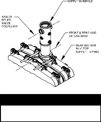
f.Install observation port sight glass. Locate 2”
x2-1/2” lg. nipple, sight glass envelope and 2” conduit bushing. Thread 2” nipple into observation port tapping directly above burner adapter opening on front of BSD. Open sight glass envelope and in this order place gasket, sight glass and gasket into conduit cap. Thread cap unto 2” nipple, hand tighten only until cap and glass are snug. Do not over tighten.
g.Do not install BSD on hinges at this time. Door must be installed after jacket assembly.
7.Mount C. I. flue collector to rear section - see Figure 9.
a.Use a wire brush to clean the rope groove on back surface of rear section.
b.Using the multi-purpose spray adhesive provided, apply the adhesive to the perimeter rope groove. Follow the directions on the can for application and tack time.
c.Locate remaining 158” length of silicone coated fiberglass rope from common parts carton.
Starting at 3 o’clock position, push rope into groove and continue around perimeter until rope overlaps the starting point. Rope should be approximately 4” longer than required. Use
apermanent black marker to mark the rope approximately 1/8” beyond point of overlap. Cut off excess with scissors or utility knife and wooden cutting block.
d.Apply a generous bead of red sealant to both ends of cut rope, push ends together and smooth excess sealant over joint with your finger.
e.Locate six (6) 3/8” flat washers and six (6) 3/8
-16 x 1-1/4” lg. cap screws from hardware bag. Thread one (1) washer and cap screw in each of the bottom tappings approximately four (4)
turns. Lift flue collector and engage bottom slots over cap screws to position unit on rear section. Install remaining hardware in four (4) upper slots and hand tighten hardware. Using a wrench, tighten hardware evenly, use an alternating pattern from top to bottom.
8.Do not install Flue Collector Clean-out Covers at this time. Covers must be installed after Jacket Rear Panels are in place.
9.Install 1/4” NPT brass plug into tapping located at
10 o’clock position on flue outlet collar. Wrench tighten plug, but do not over tighten. See Figure 9.
10.Apply thread sealant and install 3” NPT pipe plug in lower tapping on front section. Wrench tighten until water tight. See Figure 9.
11.Install Supply Manifold and 4” NPT nipple - See Figure 9.
a.Locate supply and return manifold carton marked ‘S/RM CI’ and remove contents.
b.Apply thread sealing compound to both ends of the 4” NPT nipple and install one end of the
4” NPT nipple into the non-flow arrowed end of the CI Supply Manifold and hand tighten the assembly.
c.Then - Install the threaded end of the 4” NPT nipple into 4” NPT tapping located on top of rear section.
d.Wrench - CI Supply Manifold Assembly until water tight and 1½” NPT tappings (relief valve) are aligned with front and rear axis as shown in Figure 12.
Figure 12: Orientation of Supply Manifold
NOTICE
Orientation of supply manifold is critical for proper alignment of controls and relief valve piping.
B.Assemble and Install Return Water Mixing Tube (RWMT RC) and Return Manifold into Block Assembly.
1.Locate return water mixing tube carton marked ‘RWMT RC’ and remove contents.
2.Modular return water mixing tubes start as a two
(2) tube assembly with end cap and increase with block size to become a seven (7) tube assembly with end cap. Assemble each RWMT RC in exact order shown in Table VII based on boiler size. Also refer to Figure 13.
3.Per Table VII, starting at the front, install RWMT End Cap on tube shown in next column to the right. Open ‘RH’ hardware bag and locate 3 oz. tube of sealant. Apply a continuous bead of silver silicone sealant to end of tube opposite the flared collar or ring. The end cap and each tube has a series of holes for alignment when secured together. Align the holes, push end cap over tube end with sealant and secure with four (4) #8 x 1/2 hex head screws.
27

28
Table VII: Modular Return Water Mixing Tube (RWMT RC)

Figure 13: Return Water Mixing Tube RC Assembly and Installation
29

Repeat this process for each joint, securing the previous assembly to the tube shown in next column to the right in Table VII, also refer to Figure 13
for details. If space behind the boiler is limited, on RWMT’s having two or more tubes, it may be necessary to assemble the end cap to the adjoining tube and then insert the assembly, capped end first, into the 4” NPT tapping on the back of the rear section before joining the remaining tube(s). Allow approximately 1½” of the tube to protrude from the tapping, so that the next tube can be secured to the assembly. Once the next tube is secured, insert the assembly further into the tapping. Repeat this procedure as necessary for up to seven (7) tube RWMT assemblies.
4.Insert the completed RWMT assembly into the 4” NPT tapping until the end cap reaches the front of the boiler. The front support clip on the end cap must rest on the internal shelf inside of the upper 3” NPT boss on the front section. If necessary, insert
along screw driver, wooden dowel or a short length of 1/2 pipe through the 3” NPT tapping and into the support collar on the end cap to lift and maneuver the tube into position.
5.Install CI Return Manifold and 4” NPT Nipple - See Figure 9.
a.Apply thread-sealing compound to both ends of 4” NPT nipple and hand tighten nipple into one end of the CI Return Manifold (return manifold casting is symmetrical about the ends).
b.Slide the CI Return Manifold Assembly over RWMT, and install the threaded end of the 4” NPT nipple into 4” NPT tapping in rear section.
c.Wrench CI Return Manifold Assembly until watertight and ½” NPT tappings (positioning plugs) are aligned with vertical axis of rear section as shown in Figure 14.
6.Thread upper and lower positioning plugs into 1/2” NPT tappings. If necessary, push forward or pull back on RWMT assembly and/or rotate until pins on positioning plugs engage alignment holes in tube, see Figure 13. Wrench both plugs until water tight.
7.Install RWMT front support plug into 3” NPT tapping on upper front section boss.
a.Looking through 3” tapped hole, check position of support collar on RWMT end cap. Collar should be located approximately in the center of the tapped hole both vertically and horizontally.
b.If necessary, adjust support collar position before installing front support plug. For horizontal adjustment, bend support clip up or down per the amount of visual mis-alignment.
c.Thread front support plug into 3” NPT upper front section boss, wrench plug water tight.
C.Install Jacket Support Frame to Block Assembly.
1.Locate Jacket Frame Carton(s), marked ‘JF’ and remove contents, see equipment list on Page 3 for quantity required.
2.Open “JF-P” Jacket Frame Parts Carton(s), packed inside Jacket Frame Carton(s), and remove contents.
3.Locate support channel brackets which are shipped flat and need to be hand formed by bending both legs down 90°, see Figure 15.
Figure 14: Orientation of Return Manifold
NOTICE
Orientation of return manifold is critical for proper alignment of return water mixing tube.
Figure 15: Hand Form Support Channel Bracket
4.Locate horizontal support channels and FH-1 Hardware Bag(s). Position two (2) support channel brackets on floor and place horizontal support channel over brackets. All three (3) holes in both parts must be in alignment, if they are not, rotate bracket. Secure brackets to channel using four (4) #8 x 1/2 hex head sheet metal screws, see Figure 16. Repeat until all horizontal channels and brackets are assembled.
30
 Loading...