


INSTALLATION, OPERATING AND SERVICE INSTRUCTIONS FOR
RSA™ SERIES
OIL - FIRED BOILER
For service or repairs to boiler, call your heating contractor. When seeking information on boiler, provide Boiler Model Number and Serial Number as shown on Rating Label.
Boiler Model Number |
Boiler Serial Number |
Installation Date |
|||||
RSA |
|
|
|
|
|
|
|
|
|
|
|
|
|
|
|
Heating Contractor |
|
|
|
|
|
|
Phone Number |
|
|
|
|
|
|
|
|
Address |
|
|
|
|
|
|
|
|
|
|
|
|
|
|
|
|
|
|
|
|
|
|
|
8143508R21-1/10 |
Price - $3.00 |
IMPORTANT INFORMATION - READ CAREFULLY
All boilers must be installed in accordance with National, State and Local Plumbing, Heating and Electrical Codes and the regulations of the serving utilities. These Codes and Regulations may differ from this instruction manual. Authorities having jurisdiction should be consulted before installations are made.
In all cases, reference should be made to the following Standards:
All wiring on boilers installed in the USA shall be made in accordance with the National Electrical Code and/or Local Regulations.
All wiring on boilers installed in Canada shall be made in accordance with the Canadian Electrical Code and/or Local Regulations.
USA BOILERS
A.Current Edition of American National Standard ANSI/NFPA 31, “Installation of Oil Burning Equipment”, for recommended installation practices.
B.Current Edition of American National Standard ANSI/NFPA 211, “Chimneys, Fireplaces, Vents, and Solid Fuel Burning Appliances”, For Venting requirements.
C.Current Edition of American Society of Mechanical Engineers ASME CSD-1, “Controls and Safety Devices for Automatically Fired Boilers”, for assembly and operations of controls and safety devices.
CANADIAN BOILERS
A.Current Edition of Canadian Standards Association CSA B139, “Installation Code for Oil Burning Equipment”, for recommended Installation Practices.
The following terms are used throughout this manual to bring attention to the presence of hazards of various risk levels, or to important information concerning product life.
DANGER
Indicates an imminently hazardous situation which, if not avoided, will result in death, serious injury or substantial property damage.
CAUTION
Indicates a potentially hazardous situation which, if not avoided, may result in moderate or minor injury or property damage.
WARNING
Indicates a potentially hazardous situation which, if not avoided, could result in death, serious injury or substantial property damage.
NOTICE
Indicates special instructions on installation, operation, or maintenance which are important but not related to personal injury hazards.
NOTICE
This boiler has a limited warranty, a copy of which is printed on the back of this manual.
It is the responsibility of the installing contractor to see that all controls are correctly installed and are operating properly when the installation is complete. The warranty for this boiler is valid only if the boiler has been installed, maintained and operated in accordance with these instructions.

DANGER
DO NOT store or use gasoline or other flammable vapors or liquids in the vicinity of this or any other appliance.
WARNING
Improper installation, adjustment, alteration, service or maintenance can cause property damage, personal injury or loss of life. Failure to follow all instructions in the proper order can cause personal injury or death. Read and understand all instructions, including all those contained in component manufacturers manuals which are provided with the appliance before installing, starting-up, operating, maintaining or servicing this appliance. Keep this manual and literature in legible condition and posted near appliance for reference by owner and service technician.
This boiler requires regular maintenance and service to operate safely. Follow the instructions contained in this manual. Installation, maintenance, and service must be performed only by an experienced, skilled and knowledgeable installer or service agency. All heating systems should be designed by competent contractors and only persons knowledgeable in the layout and installation of hydronic heating systems should attempt installation of any boiler. It is the responsibility of the installing contractor to see that all controls are correctly installed and are operating properly when the installation is completed. Installation is not complete unless a pressure relief valve is installed into the tapping located on top of appliance - See Section III of this manual for details.
This boiler is not suitable for installation on combustible flooring, unless installed with a combustible floor shield (available at extra cost).
Do not install boiler on carpeting.
When boiler is installed on concrete which is over a material that is subject to melting (PVC, PEX radiant tubing, etc.) the combustible floor shield must be used.
A concrete pad is not sufficient to protect combustible flooring.
Do not tamper with or alter the boiler or controls. Retain your contractor or a competent serviceman to assure that the unit is properly adjusted and maintained.
Have Firetubes cleaned at least once a year - preferably at the start of the heating season to remove soot and scale. The inside of combustion chamber should also be cleaned and inspected at the same time.
Have Oil Burner and Controls checked at least once a year or as may be necessitated. Do not operate unit with jumpered or absent controls or safety devices.
Do not operate unit if any control, switch, component, or device has been subject to water.
Appliance materials of construction, products of combustion and the fuel contain alumina, silica, heavy metals, carbon monoxide, nitrogen oxides, aldehydes and/or other toxic or harmful substances which can cause death or serious injury and which are known to the state of California to cause cancer, birth defects andotherreproductiveharm. Always usepropersafety clothing,respirators andequipmentwhen servicing or working nearby the boiler.
This boiler is designed to burn No. 2 fuel oil only. Do not use gasoline, crankcase drainings, or any oil containing gasoline. Never burn garbage or paper in this boiler. Do not convert to any solid fuel (i.e. wood, coal). Do not convert to any gaseous fuel (i.e. natural gas, LP). All flammable debris, rags, paper, wood scraps, etc., should be kept clear of the boiler at all times.
Keep the boiler area clean and free of fire hazards.

WARNING
This boiler contains very hot water under high pressure. Do not unscrew any pipe fittings nor attempt to disconnect any components of this boiler without positively assuring the water is cool and has no pressure. Always wear protective clothing and equipment when installing, starting up or servicing this boiler to prevent scald injuries. Do not rely on the pressure and temperature gauges to determine the temperature and pressure of the boiler. This boiler contains components which become very hot when the boiler is operating. Do not touch any components unless they are cool.
This appliance must be properly vented and connected to an approved vent system in good condition. Serious property damage could result if the boiler is connected to an approved vent system.
This boiler needs fresh air for safe operation and must be installed so there are provisions for adequate combustion and ventilation air.
The interior of the venting and air intake systems must be inspected and cleaned before the start of the heating season and should be inspected periodically throughout the heating season for any obstructions. Clean and unobstructed venting and air intake systems are necessary to allow noxious fumes that could cause injury or loss of life to vent safely and will contribute toward maintaining the boiler’s efficiency.
This boiler is supplied with controls which may cause the boiler to shut down and not re-start without service. If damage due to frozen pipes is a possibility, the heating system should not be left unattended in cold weather; or appropriate safeguards and alarms should be installed on the heating system to prevent damage if the boiler is inoperative.
Donotoperateboileroncombustiblefloorwithoutafactorysuppliedfloorshield. Concreteoverwoodjoists is considered combustible flooring. Do not operate on masonry floors, which may contain moisture.

Table of Contents
I. |
Pre-Installation........................................ |
7 |
VI. |
Oil Piping.............................................. |
28 |
II. |
Knockdown Boiler Assembly................. |
9 |
VII. System Start-Up.................................... |
30 |
|
III. |
Water Piping and Trim.......................... |
12 |
VIII. Service and Cleaning............................ |
38 |
|
IV. |
Venting.................................................. |
18 |
IX. |
Repair Parts........................................... |
40 |
V. |
Electrical and Sequence of Operation... |
20 |
X. |
Appendix |
|
|
|
|
|
Low Water Cut Off............................... |
50 |
|
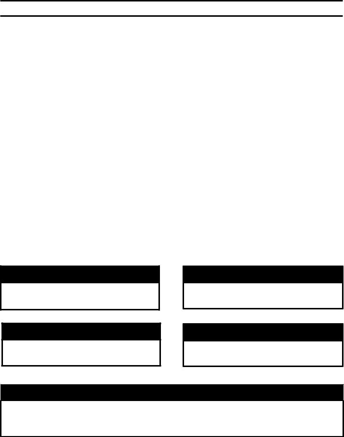
Dim. ‘A’ |
Minimum Recommended Chimney Sizes |
Water |
Approx. |
||
Boiler Model Number |
In. x In. x Ft. (ht.) |
In. (dia.) x Ft. (ht.) |
Capacity |
Shipping |
||
|
|
(gallons) |
Weight (lb.) |
|||
|
|
|
|
|||
RSA85 |
34¾ |
|
|
9.1 |
300 |
|
RSA110 |
8 x 8 x 20 |
6 x 15 |
8.5 |
|||
|
|
|||||
RSA125 |
41¼ |
|
13.9 |
340 |
||
|
|
|||||
RSA135 |
|
7 x 15 |
13.0 |
355 |
||
|
|
|||||
Figure 1: RSA Packaged Boiler (RSA85 / RSA135)
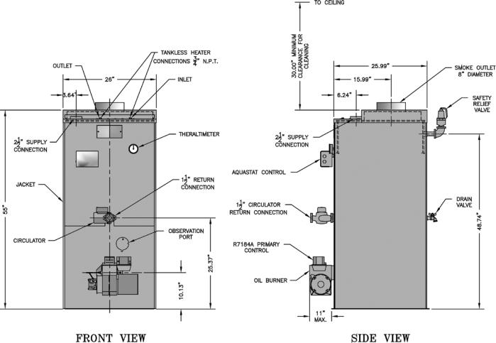
Figure 1A: RSA Packaged Boiler (RSA170 / RSA285)
Boiler |
Bare Boiler |
Minimum Recommended Chimney Sizes |
Water |
Approx. |
||
Model |
|
|
Capacity |
Shipping |
||
Assembly |
In. x In. x Ft. (height) |
In. (dia.) x Ft. (height) |
||||
Number |
(gallons) |
Weight (lb.) |
||||
|
|
|
||||
RSA170 |
WV-29-10 |
8 x 8 x 20 |
7 x 20 |
42.6 |
600 |
|
RSA195 |
WV-29-13A |
8 x 20 |
39.9 |
630 |
||
|
||||||
RSA240 |
WV-29-16A |
8 x 12 x 20 |
37.3 |
660 |
||
|
||||||
RSA285 |
WV-29-19A |
9 x 20 |
34.6 |
690 |
||
|
||||||
I. Pre-Installation
A. INSPECT SHIPMENT carefully for any signs of damage.
1.ALL EQUIPMENT is carefully manufactured, inspected and packed. Our responsibility ceases upon delivery of the crated boiler to the carrier in good condition.
2.ANY CLAIMS for damage or shortage of shipment must filed immediately against the carrier by
the consignee. No claims for variances from, or shortage in orders, will be allowed by the
manufacturer unless presented within sixty (60) days after receipt of goods.
B. LOCATE BOILER in front of final position before removing crate.
CAUTION
Do not drop boiler. Do not bump boiler jacket against floor.
1.LOCATE so that smoke pipe connection to chimney will be short and direct. BOILER IS NOT SUITABLE FOR INSTALLATION ON
COMBUSTIBLE FLOOR unless combustible floor shield, supplied by Burnham, is used. DO NOT
install on carpeting. See Figure 26 for floor shield part number and installation instructions.
2.FOR BASEMENT INSTALLATION, provide a solid base, such as concrete, if floor is not level, or if water may be encountered on floor around boiler.
3.PROVIDE SERVICE CLEARANCE of at least 48” from the front of the jacket for servicing of burner and removal of tankless heater.
For minimum clearances to combustible materials. See Figure 2.
WARNING
Do not support boiler by placing blocks at the four (4) corners of the boiler.
Boiler base must be evenly supported under entire base.
Do not operate boiler on combustible floor without a factory supplied floor shield. Concrete over wood joists is considered combustible flooring. Do not operate on masonry floors, which may contain moisture.
Figure 2: Minimum Clearances to Combustible Materials
NOTE:
1.Listed clearances comply with American National Standard ANSI/NFPA 31, Installation of Oil Burning Equipment.
2.RSA™ boilers can be installed in rooms with clearances from combustible material as listed above. Listed clearances can not be reduced for alcove or closet installations.
3.For reduced clearances to combustible material, protection must be provided as described in the above ANSI/NFPA 31 standard.

C.PROVIDE COMBUSTION AND VENTILATION AIR. Local code provisions may apply and should be referenced.
WARNING
Adequate combustion and ventilation air must be provided to assure proper combustion and to maintain safe ambient air temperatures.
Do not install boiler where gasoline or other flammable vapors or liquids, or sources of hydrocarbons (i.e. bleaches, fabric softeners, etc.) are used or stored.
1.Determine volume of space (boiler room). Rooms communicating directly with the space in which the appliances are installed, through openings not furnished with doors, are considered a part of the space.
Volume(ft3) = Length(ft) x Width(ft) x Height(ft)
2.Determine total input of all appliances in the space.
Add inputs of all appliances in the space and round the result to the nearest 1000 BTU per hour.
3.Determine type of space. Divide Volume by total input of all appliances in space. If the result is greater than or equal to 50 ft3/1000 BTU per hour, then it is considered an unconfined space. If the result is less than 50 ft3/1000 BTU per hour then the space is considered a confined space.
4.For boiler located in an unconfined space of a conventionally constructed building, the fresh air infiltration through cracks around windows and doors normally provides adequate air for combustion and ventilation.
5.For boiler located in a confined space or an unconfined space in a building of unusually tight construction, provide outdoor air with the use of two permanent openings which communicate directly or by duct with the outdoors or spaces (crawl or attic) freely communicating with the outdoors. Locate one
opening within 12 inches of top of space. Locate remaining opening within 12 inches of bottom of space. Minimum dimension of air opening is 3 inches. Size each opening per following:
a.Direct communication with outdoors.
Minimum free area of 1 square inch per 4,000 BTU per hour input of all equipment in space.
b.Vertical ducts. Minimum free area of 1 square inch per 4,000 BTU per hour input of all equipment in space. Duct cross-sectional area shall be same as opening free area.
c.Horizontal ducts. Minimum free area of 1 square inch per 2,000 BTU per hour input of all equipment in space. Duct cross-sectional area shall be same as opening free area.
Alternate method for boiler located within confined space. Use indoor air if two permanent openings communicate directly with additional space(s) of sufficient volume such that combined volume of all spaces meet criteria for unconfined space. Size each opening for minimum free area of 1 square inch per 1,000 BTU per hour input of all equipment in spaces, but not less than 100 square inches.
6.Louvers and Grilles of Ventilation Ducts
a.All outside openings should be screened and louvered. Screens used should not be smaller than 1/4 inch mesh. Louvers will prevent the entrance of rain and snow.
b.Free area requirements need to consider the blocking effect of louvers, grilles, or screens protecting the openings. If the free area of the louver or grille is not known, assume wood louvers have 20-25 percent free area and metal louvers and grilles have 60-75 percent free area.
c.Louvers and grilles must be fixed in the open position, or interlocked with the equipment to open automatically during equipment operation.
II. Knock-Down Boiler Assembly
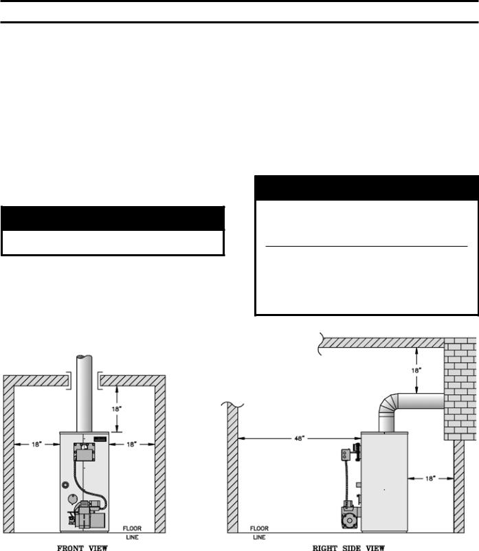
A. REMOVAL OF BOILER.
1.Remove, all boiler to skid, hold down fasteners. Refer to Figure 3.
2.Carefully walk boiler to the edge of skid. Tilt the boiler back, allowing an edge to rest on the floor, and remove the skid.
Figure 3: Base on Skid
B. TEST HEAT EXCHANGER FOR LEAKS before proceeding with jacket assembly. Heat exchanger, canopy, and base are preassembled.
1.Install pressure gauge supplied, a hose to the city water and a valve in the supply tapping. Plug remainder of tappings.
2.Fill boiler with water and apply a pressure of at least 10 psig but no more than 30 psig.
WARNING
Do not apply more than 30 psig to boiler.
WARNING
Any combustion chamber which was damaged must be replaced immediately.
CAUTION
If heat exchanger is not square on base DO NOT twist. Carefully lift and reposition.
WARNING
Do not assemble boiler without cerafelt gaskets between heat exchanger and combustion chamber. Gaskets must also be between canopy and heat exchanger.
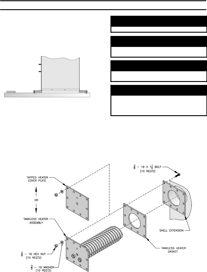
C.INSTALLING THE JACKET
1.Before jacket can be secured to boiler assembly tankless heater coil or blank plate must be attached. Using rubber gasket and bolts provided secure heater coil or blank plate to boiler extension
by inserting the bolts from the backside of the extension. Refer to Figure 4.
Figure 4: Coil Plate Attachment

2.Bend jacket according to Figure 28. Starting from the front, wrap the jacket around the boiler. Make sure that return pipe, observation port and shell extension fit proper into there corresponding clearance holes. Continue bending jacket around until front panels meet.
3.Attach jacket to boiler assembly with provided screws at appropriate locations. Make sure that the jacket is at least ½” to ¾” off of the floor before attaching.
4.Attach top panel with provided screws.
D. INSTALLATION OF BOILER CONTROLS
1.Install provided pressure/temperature gauge and immersion well into appropriate holes on tankless heater coil plate. Tighten so not to have any water leaks.
2.Mount the aquastat control onto the immersion well. Wire the control according to Figure 13 or 14, in the Electrical and Sequence of Operation Section.
3.Mount burner on Base front panel and wire according to instructions provided with the burner. Refer to Figure 5.
Figure 5: Burner Mounting
10
THIS PAGE IS LEFT INTENTIONALLY BLANK
11
III. Water Piping and Trim
WARNING
Failure to properly pipe boiler may result in improper operation and damage to boiler or structure.
Oxygen contamination of boiler water will cause corrosion of iron and steel boiler components, and can lead to boiler failure. Burnham’s Standard Warranty does not cover problems caused by oxygen contamination of boiler water or scale (lime) build-up caused by frequent addition of water.
A.Design a piping system and install boiler which will prevent oxygen contamination of boiler water and frequent water additions.
1.There are many possible causes of oxygen contamination such as:
a.Addition of excessive make-up water as a result of system leaks.
b.Absorption through open tanks and fittings.
c.Oxygen permeable materials in the distribution system.
2.In order to insure long product life, oxygen sources should be eliminated. This can be accomplished by taking the following measures:
a.Repairing system leaks to eliminate the need for addition of make-up water.
b.Eliminating open tanks from the system.
c.Eliminating and/or repairing fittings which allow oxygen absorption.
d.Use of non-permeable materials in the distribution system.
e.Isolating the boiler from the system water by installing a heat exchanger.
WARNING
System supply and return piping must be connected to correct boiler pipe.
Burnham recommends sizing the system circulator to supply sufficient flow (GPM) to allow a 20°F temperature differential in the system. When sizing the system circulator, the pressure drop of all radiators, baseboard and radiant tubing and all connecting piping must be considered.
3.Connect System supply and return piping to boiler. See Figures 8 and 9. Also, consult I=B=R Installation and Piping Guides. Maintain
minimum ½ inch clearance from hot water piping to combustible materials.
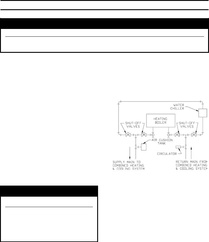
a.If this boiler is used in connection with refrigeration systems, the boiler must be installed so that the chilled medium is piped in parallel with the heating boiler using appropriate valves to prevent the chilled medium from entering
the boiler. See Figure 7. Also, consult I=B=R Installation and Piping Guides.
Figure 7: Recommended Piping for Combination Heating and Cooling (Refrigeration) System
b.If this boiler is connected to heating coils located in air handling units where they may be exposed to refrigerated air, the boiler piping must be equipped with flow control valves to prevent gravity circulation of boiler water during the operation of the cooling system.
c.If boiler is used with an Alliance™ Indirect-Fired Domestic Water Heater, install the Alliance™ as a separate heating zone. Refer to the Alliance™ Installation, Operating, and Service Instructions for additional information.
d.Use a system bypass if the boiler is to be operated in a system which has a large volume or excessive radiation where low boiler water temperatures may be encountered (i.e. converted gravity circulation system, etc.) The bypass should be the same size as the supply and return lines with valves located in the bypass
12

and return line as illustrated in Figures 8 and 9 in order to regulate water flow for maintenance of higher boiler water temperature. Set the bypass and return valves to a half throttle position to start. Operate boiler until the system water temperature reaches its normal operating range. Adjust the valves to maintain 180°F to 200°F boiler water temperature and greater the 120°F return temperature. Adjust both valves simultaneously. Closing the boiler return valve while opening the bypass valve will raise the boiler return temperature. Opening the boiler return valve while closing the by-pass valve will lower the boiler return temperature.
e.A water boiler installed above radiation level must be provided with a low water cutoff device as part of the installation.
If a low water cut-off is required, it must be mounted in the system piping above the boiler.
The minimum safe water level of a hot water boiler is just above the highest water containing cavity of the boiler; that is, a hot water boiler must be full of water to operate safely.
B. Install Safety Relief Valve. See Figures 8 and 9. Safety Relief Valve must be installed with spindle in the vertical position. Installation of the relief valve
must be consistent with ANSI/ASME Boiler and Pressure Vessel Code, Section IV.
WARNING
Safety (relief) valve discharge piping must be piped near floor to eliminate potential of severe burns. Do not pipe in any area where freezing could occur. Do not install any shut-off valves, plugs or caps.
C.Install Drain Valve in return piping. See Figures 8 and 9.
D. Oil, grease, and other foreign materials which accumulate in new hot water and a new or reworked system should be boiled out, and then thoroughly flushed. A qualified water treatment chemical specialist should be consulted for recommendations regarding appropriate chemical compounds and concentrations which are compatible with local environmental regulations.
E. After the boiler and system have been cleaned and flushed, and before refilling the entire system add appropriate water treatment chemicals, if necessary, to bring the pH between 7 and 11.
WARNING
Installation is not complete unless a safety relief valve is installed as shown in Figure 1 or 1A.
13

14
Figure 8: Recommended Water Piping for Circulator Zoned Heating Systems

15
Figure 9: Recommended Water Piping for Zone Valve Zoned Heating Systems

F. CONNECT TANKLESS HEATER PIPING AS SHOWN IN FIGURE 10. See Table 1 for Tankless Heater Rating.
WARNING
Install automatic mixing valve at tankless heater outlet to avoid risk of burns or scalding due to excessively hot water at fixtures. Adjust and maintain the mixing valve in accordance with the manufacturer's instructions. Do not operate tankless heater without mixing valve.
THE FOLLOWING GUIDELINES SHOULD BE FOLLOWED WHEN PIPING THE TANKLESS HEATER:
1.FLOW REGULATION — If flow through the heater is greater than its rating, the supply of adequate hot water may not be able to keep up with the demand.
For this reason a flow regulator matching the heater rating should be installed in the cold water line to the heater. The flow regulator should preferably be located below the inlet to the heater and a minimum of 3’ away from the inlet so that the regulator is not subjected to excess temperatures that may occur during “off” periods when it is possible for heat
to be conducted back through the supply line. The flow regulator also limits the flow of supply water regardless of inlet pressure variations in the range of 20 to 125 psi.
2.TEMPERING OF HOT WATER — Installation of an automatic mixing valve will lengthen the delivery of the available hot water by mixing some cold water with the hot. This prevents the possibility
of scalding hot water at the fixtures. In addition, savings of hot water will be achieved since the user will not waste as much hot water while seeking a water temperature. Higher temperature hot water required by dishwashers and automatic washers is possible by piping the hot water from the heater prior to entering the mixing valve. The mixing valve should be “trapped” by installing it below the cold water inlet to heater to prevent lime formation in the valve. Refer to Figure 10.
3.FLUSHING OF HEATER — All water contains some sediment which settles on the inside of the coil. Consequently, the heater should be periodically backwashed. This is accomplished by installing hose bibs as illustrated and allowing water at city pressure to run into hose bib A, through the heater, and out hose bib B until the discharge is clear. The tees in which the hose bibs are located should be the same size as heater connections to minimize pressure drop.
4.HARD WATER — A water analysis is necessary to determine the hardness of your potable water. This is applicable to some city water and particularly to well water. An appropriate water softener should be installed based on the analysis and dealer’s recommendation. This is not only beneficial to the tankless heater but to piping and fixtures plus the many other benefits derived from soft water.
16
 Loading...