


Price - $3.00
INSTALLATION,
OPERATING AND SERVICE
INSTRUCTIONS FOR
V7 SERIES OIL FIRED BOILER KNOCKDOWN & PACKAGED HEATING UNITS 

As an ENERGY STAR® Partner,
Burnham Corporation has determined that the V73WR (0.60 GPH), V74WR (0.80 GPH), V75WR (0.90 GPH), and V76WR (1.15 GPH)
meet the ENERGY STAR® guidelines for Energy efficiency established by the United States Environmental Protection Agency (EPA).
These instructions have been reviewed by ULC and found suitable for use in the installation of ULC labeled V-7 Series Boilers.
The ULC label or listed marking on a product is the only evidence provided by Underwriters' Laboratories of Canada to identify products which have been produced under the listing and follow-up service.
For service or repairs to boiler, call your heating contractor. When seeking information on boiler, provide Boiler Model Number and Serial Number as shown on Rating Label.
Boiler Model Number |
Boiler Serial Number |
Installation Date |
_V7 ____-____ |
6_ _ _ _ _ _ _ |
Heating Contractor |
Phone Number |
Address
8142711R24-7/99 |
1 |
|

IMPORTANT INFORMATION - PLEASE READ THIS PAGE CAREFULLY
1.THIS BOILER HAS LIMITED WARRANTIES, COPIES OF WHICH ARE PRINTED ON THE BACK COVER OF THIS MANUAL.
2.THIS BOILER IS SUITABLE FOR INSTALLATION ON COMBUSTIBLE FLOORING. BOILER CANNOT BE INSTALLED ON CARPETING.
3.ALL BOILERS MUST BE INSTALLED IN ACCORDANCE WITH NATIONAL, STATE AND LOCAL PLUMBING, HEATING AND ELECTRICAL CODES AND THE REGULATIONS OF THE SERVING UTILITIES WHICH MAY DIFFER FROM THIS MANUAL. AUTHORITIES HAVING JURISDICTION SHOULD BE CONSULTED BEFORE INSTALLATIONS ARE MADE.
IN ALL CASES, REFERENCE SHOULD BE MADE TO THE FOLLOWING STANDARDS:
USA BOILERS
A.Current Edition of American National Standard ANSI/NFPA 31, “Installation of Oil Burning Equipment”, for clearances between boiler, vent connector and combustible material.
B.Current Edition of American National Standard ANSI/NFPA 211, “Chimneys, Fireplaces, Vents, and Solid Fuel Burning Appliances”, For Chimney requirements, type of venting material and clearances between vent connector pipe and combustible materials.
C.Current Edition of American Society of Mechanical Engineers ASME CSD-1, “Controls and Safety Devices for Automatically Fired Boilers”, for assembly and
operations of controls and safety devices.
CANADA BOILERS
A.Current Edition of Canadian Standards Association CSA B139, “Installation Code for Oil Burning Equipment”, for recommended Installation Practices.
4.ALL HEATING SYSTEMS SHOULD BE DESIGNED BY COMPETENT CONTRACTORS AND ONLY PERSONS KNOWLEDGEABLE IN THE LAYOUT AND INSTALLATION OF HYDRONIC HEATING SYSTEMS SHOULD ATTEMPT INSTALLATION OF ANY BOILER.
5.THE BOILER MUST BE CONNECTED TO AN APPROVED CHIMNEY IN GOOD CONDITION. SERIOUS PROPERTY DAMAGE COULD RESULT IF THE BOILER IS CONNECTED TO A DIRTY OR INADEQUATE CHIMNEY. THE INTERIOR OF THE CHIMNEY FLUE MUST BE INSPECTED AND CLEANED BEFORE THE START OF THE HEATING SEASON AND SHOULD BE INSPECTED PERIODICALLY THROUGHOUT THE HEATING SEASON FOR ANY OBSTRUCTIONS. A CLEAN AND UNOBSTRUCTED CHIMNEY FLUE IS NECESSARY TO ALLOW NOXIOUS FUMES THAT COULD CAUSE INJURY OR LOSS OF LIFE TO VENT SAFELY AND WILL CONTRIBUTE TOWARD MAINTAINING THE BOILER’S EFFICIENCY.
6.READ THE LITERATURE ENCLOSED BY THE MANUFACTURER WITH THE VARIOUS ACCESSORY DEVICES. THESE ACCESSORY DEVICES MUST BE INSTALLED AND USED ACCORDING TO THE RECOMMENDATIONS OF THE MANUFACTURER.
7.IT IS THE RESPONSIBILITY OF THE INSTALLING CONTRACTOR TO SEE THAT ALL CONTROLS ARE CORRECTLY INSTALLED AND ARE OPERATING PROPERLY WHEN THE INSTALLATION IS COMPLETED.
8.FOR OPTIMUM PERFORMANCE AND SERVICEABILITY FROM THIS BOILER ADHERE TO THE FOLLOWING RECOMMENDATIONS:
A.DO NOT TAMPER WITH THE BOILER OR CONTROLS. Retain your contractor or a competent serviceman to assure that the boiler is properly adjusted and maintained.
B.Clean flueways at least once a year - preferably at the end of the heating season to remove soot and scale. Inside of firebox should also be cleaned at the same time.
C.Have oil burner and controls checked at least once a year or as may be necessitated.
WARNING
This boiler is designed to burn No. 2 fuel oil only. Do not use gasoline, crankcase drainings, or any oil containing gasoline. Never burn garbage or paper in this boiler. Do not convert to any solid fuel (i.e. wood, coal) or gaseous fuel (i.e. natural gas, LP/propane). All flammable debris, rags, paper, wood scraps, etc., should be kept clear of the boiler at all times. Keep the boiler area clean and free of fire hazards.
WARNING
All boilers equipped with burner swing door have a potential hazard which can cause severe property damage, personal injury or loss of life if ignored. Before opening swing door, turn off service switch to boiler to prevent accidental firing of burner outside the combustion chamber. Be sure to tighten swing door fastener completely when service is completed.
WARNING
High water temperatures increase the risk of burns or scalding injury. Install an automatic tempering (mixing) valve at the tankless heater outlet to avoid excessively hot water at the fixtures.
2

IMPOR TANT
Before starting to install this oil boiler, read these instructions carefully. Keep instructions in legible condition and posted near oil boiler for reference by owner and service technician .
TABLE OF CONTENTS
I. |
General Information ............................. |
3 |
IV. |
Operating Instructions ........................ |
21 |
II. |
Knockdown Boiler Assembly ............... |
7 |
V. |
Boiler Cleaning .................................. |
29 |
III. |
Installation Instructions ...................... |
12 |
VI. |
Repair Parts ........................................ |
31 |
|
|
|
|
Burner Specifications ......................... |
46 |
SECTION I: GENERAL INFORMATION
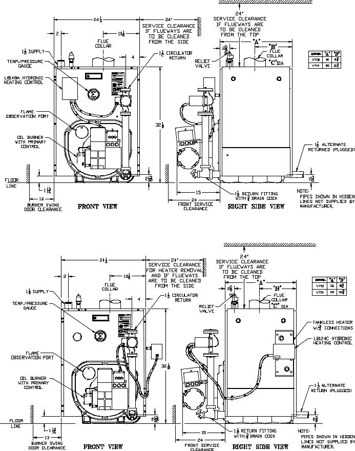
Figure 1A: V72 thru V79 Water Boiler Without Tankless Heater (WB)
TABLE 1: DIMENSIONAL DATA (SEE FIGURES 1A THRU 1E)
|
|
|
|
|
|
|
|
Heat Transfer |
|
Boiler |
Dimensions |
|
Minimum |
Water Content - |
Surface Area - |
Approximate |
|||
Model |
|
|
|
|
Gallons |
Sq. Ft. |
Shipping Weight |
||
|
|
|
|
Chimney Size |
|||||
No. |
"A" |
"B" |
|
"C" |
Steam |
Water |
Steam Boiler |
(LB.) |
|
|
|
||||||||
|
|
|
Boiler |
Boiler |
|
||||
|
|
|
|
|
|
|
|
||
|
|
|
|
|
|
|
|
|
|
V72 |
11-3/8" |
6-3/8" |
|
5" |
8" x 8" x 15' |
---- |
10.6 |
---- |
381 |
|
|
|
|
|
|
|
|
|
|
V713 |
16" |
8-3/4" |
|
6" |
8" x 8" x 15' |
---- |
13.5 |
---- |
524 |
|
|
|
|
|
|
|
|
|
|
V73 |
15-3/8" |
8-3/8" |
|
6" |
8" x 8" x 15' |
10.8 |
13.2 |
13.8 |
478 |
|
|
|
|
|
|
|
|
|
|
V714 |
20" |
10-3/4" |
|
6" |
8" x 8" x 15' |
---- |
15.9 |
---- |
580 |
|
|
|
|
|
|
|
|
|
|
V74 |
19-3/8" |
10-3/8" |
|
6" |
8" x 8" x 15' |
13.5 |
15.9 |
19.7 |
575 |
|
|
|
|
|
|
|
|
|
|
V75 |
23-3/8" |
12-3/8" |
|
7" |
8" x 8" x 15' |
16.1 |
18.5 |
25.6 |
674 |
|
|
|
|
|
|
|
|
|
|
V76 |
27-3/8" |
14-3/8" |
|
7" |
8" x 8" x 15' |
18.6 |
21 |
31.4 |
773 |
|
|
|
|
|
|
|
|
|
|
V77 |
31-3/8" |
16-3/8" |
|
8" |
8" x 12" x 15' |
21.2 |
23.6 |
37.3 |
872 |
|
|
|
|
|
|
|
|
|
|
V78 |
35-3/8" |
18-3/8" |
|
8" |
8" x 12" x 15' |
23.8 |
26.2 |
43.1 |
971 |
|
|
|
|
|
|
|
|
|
|
V79 |
39-3/8" |
20-3/8" |
|
8" |
8" x 12" x 15' |
26.4 |
28.8 |
49.0 |
1070 |
|
|
|
|
|
|
|
|
|
|
|
NOTE: |
1. Maximum Working Pressure 15 PSI (Steam) and 30 PSI (Water) |
|
||||||
2.The V72, V713 and V714 Boilers are available as packaged water boilers only
3.The V713 and V714 are not ULC listed Models
3

Figure 1B: V73 thru V79 Water Boiler with Tankless Heater (WBT)
Figure 1C: V73 thru V79 Steam Boiler with or without Tankless Heater ("SBT" or "SB")
4

 Β υ ρ ν η α µ
Figure 1D: V713 and V714 Packaged Water Boiler Less Tankless Heater (WB)
Burnham 
Figure 1E: V713 and V714 Packaged Water Boiler with Tankless Heater (WBT)
5

A.INSPECT SHIPMENT carefully for any signs of damage.
1.ALL EQUIPMENT is carefully manufactured, inspected and packed. Our responsibility ceases upon delivery of crated boiler to the carrier in good condition.
2.ANY CLAIMS for damage or shortage in shipment must be filed immediately against the carrier by the consignee. No claims for variances from, or shortage in orders, will be allowed by the manufacturer unless presented within sixty (60) days after receipt of goods.
B.LOCATE BOILER in front of final position before removing crate. See Figures 1A thru 1E.
1.LOCATE so that smoke pipe connection to chimney will be short and direct. BOILER IS SUITABLE FOR INSTALLATION ON COMBUSTIBLE FLOOR. Boiler cannot be installed on carpeting.
TABLE 2: Minimum Installation Clearances To
Combustible Materials (Inches)
|
|
|
C |
|
|
|
A |
B |
Chimney |
D |
E |
Boiler |
Above |
Front |
Connector |
Rear |
Sides |
|
|
|
|
|
|
V7 |
6 |
24 |
18 |
6 |
6 |
|
|
|
|
|
|
2.FOR BASEMENT INSTALLATION, provide a solid base, such as concrete, if floor is not level, or if water may be encountered on floor around boiler.
3.PROVIDE SERVICE CLEARANCE of at least 24” on right side of boiler for removal of rear tankless heater. Provide at least 24” clearance from front jacket panel for servicing and removal of front tankless heater (increase to 30" for #A54 heater). Provide at least 24" clearance from right side of boiler or top of boiler for cleaning flueways. Boiler flueways may be cleaned either from the top or from the side.
4.For minimum clearances to combustible materials. See Table 2.
C.PROVIDE AIR SUPPLY AND VENTILATION to accommodate proper combustion. If natural ventilation is inadequate, provide a screened opening or duct from the boiler room to the outside. The opening or duct must be sized so the boiler input will not exceed 4,000 BTUH/Sq. In. of free area. If other air consuming appliances are near the boiler, the air inlet should be larger. Consult respective manufacturers.
NOTE 1: Listed clearances comply with American National Standard ANSI/NFPA 31, Installation of Oil Burning Equipment.
NOTE 2: V7 Series boilers can be installed in rooms with clearances from combustible material as listed above. Listed clearances cannot be reduced for alcove or closet installations.
NOTE 3: For reduced clearances to combustible material, protection must be provided as described in the above ANSI/NFPA 31 standard.
6

SECTION II: KNOCKDOWN BOILER ASSEMBLY
Note: If Boiler is Packaged Go To Section III
A.REMOVAL OF BARE BOILER FROM SKID
1.Boiler is secured to base with 4 bolts, 2 on front and 2 on rear, see Figure 2. Remove all bolts.
2.Tilt boiler to right and to rear. Using right rear leg as pivot, rotate boiler 90° in a clockwise direction, and lower left side of boiler to floor. Tilt boiler and remove crate skid.
section as shown in Fig. 3. Place gaskets so as not to allow any flueway blockage.
2.Cut the remainder of the roll into two (2) equal pieces. Place each piece along the sides, allowing the ends to overlap the front and rear pieces.
Do not allow any flueway blockage.
3.Position canopy body within the retaining bar which borders the flueway openings on top of the bare boiler block assembly.
Figure 2
B.MOVE BOILER TO PERMANENT POSITION by sliding or walking.
C.TEST BOILER FOR LEAKS before installing controls, trim, and jacket, and before connecting to heating system.
1.Loosen nuts on tie rods until only finger tight.
2.Install pressure gauge (at least 30 P.S.I. capacity), a hose to the city water and a valve in the supply tapping. Plug remainder of tappings.
3.Fill boiler with water and apply a pressure of at least 10 pounds but no more than 30 pounds gauge pressure.
4.Examine Boiler carefully inside and outside for leaks or damage due to shipment or handling.
D.DRAIN WATER FROM BOILER. Remove gauge, valve and plugs from those tappings to be used. Leave other tappings plugged or bushed according to Figure
E.INSPECT JOINTS BETWEEN SECTIONS. All joints are factory sealed. If there are any spaces due to shipment or handling, seal them with boiler putty.
F.INSPECT FLUE COVER PLATES for tightness. If loose, retighten mounting hardware. If flue plate or sealing insulation is damaged repair or replace as needed.
G.INSTALL AND SECURE CANOPY with cerafelt gasket and hardware provided to ensure gas tight seal
— see Figure 3.
1.Cut two (2) strips 13 ¾” lg. from the roll of cerafelt gasket insulation. Place one (1) strip across the top of the front section and the other across the rear
Figure 3
IMPORTANT: Jacket support bracket must be facing left side of boiler — see Figure 3.
4.Secure canopy to boiler with two (2) 1/4" - 20 x 3" lg. carriage bolts, 1/4" flat washers and 1/4" - 20 wing nuts provided.
H.INSTALL the following steam or water trim that would be concealed or inaccessible after flush jacket is installed, see Figure 4 for boiler tapping locations and usage.
1.STEAM BOILER — Top tappings:
a.Tapping "L" — Install 2" plug in rear section top supply tapping on boiler sizes V73 thru V75.
b.Tapping “M” — Install ¾” coupling and ¾” x 8” long nipple into ¾” tapping located next to front section top supply tapping — all boiler sizes.
2.WATER BOILER — Top tappings:
a.Tapping “L” — Install 2” plug in rear section top supply tapping on boiler sizes V73 thru V79.
7
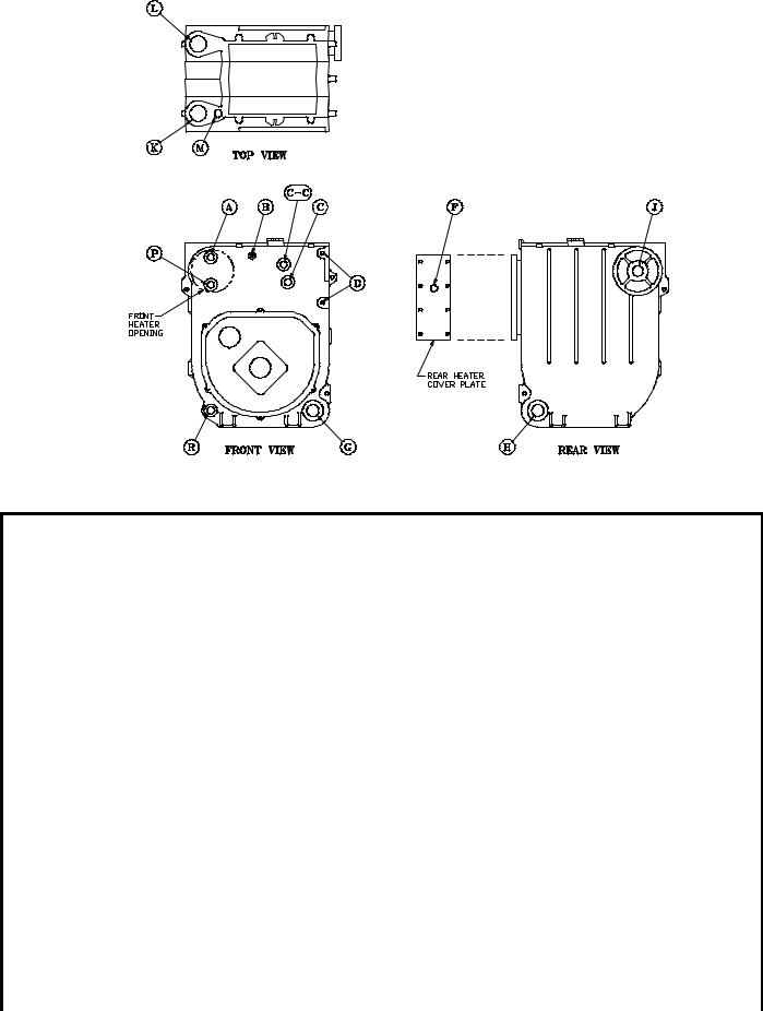
Figure 4: Boiler Tapping Locations and Usage (Knockdown Boilers Only)
PU R P O SE O F TA PP IN G S
Tap p in g |
S ize |
|
S te am B o ile r |
|
W a te r B oiler |
|
||
L oca tion |
|
|
|
|||||
|
|
|
|
|
|
|||
|
|
|
|
|
|
|
||
|
|
No n -H e a ter |
|
w /H ea te r |
No n -H e a ter |
F ro n t He a te r |
R e ar H e a ter |
|
|
|
|
|
|
|
|
||
A |
¾ " |
PA 4 04A P res su retro l (P robe LW CO ) |
L 81 48A |
L81 24 C |
Flush Plu g |
|||
P lugg ed (Flo at LW CO ) |
Op era tin g C on trol |
Op era tin g C on trol |
||||||
|
|
|
||||||
|
|
|
|
|
|
|
||
B |
¼ " |
P re ss ure /Va cu um G aug e |
Tem p era tu re/P re ss ure G aug e |
|||||
|
|
|
|
|
|
|
||
C |
¾ " |
P ro be LW C O Std. |
|
Flush Plu g |
|
|||
P lugg ed (Flo at LW CO ) |
|
|
||||||
|
|
|
|
|
||||
|
|
|
|
|
|
|
|
|
C- C |
¾ " |
Flush Plu g |
|
Flush Plu g |
|
Flush Plu g |
|
|
|
|
|
|
|
|
|
||
D |
½ " |
W ater Gau ge Glas s (P r obe LW CO ) |
|
Flush Plu g |
|
|||
W ater G aug e G lass , P re ss uretrol, a nd LW CO (Flo at) |
|
|
||||||
|
|
|
|
|
||||
|
|
|
|
|
|
|
|
|
F |
¾ " |
----- |
|
L4 006 A Op era tin g |
----- |
Dis re gard |
L81 24 C |
|
|
C on trol |
Op era tin g C on trol |
||||||
|
|
|
|
|
|
|||
|
|
|
|
|
|
|
||
G |
1½ " |
B us he d to ¾ " for Drainc oc k (O ptiona l Re tu rn ) |
|
R eturn |
|
|||
|
|
|
|
|
|
|
|
|
H |
1½ " |
|
R eturn |
B us he d to ¾ " for Drainc oc k (O ptiona l Re tu rn ) |
||||
|
|
|
|
|
|
|
||
J |
1½ " |
S u rfac e B low off - Plu gge d |
|
Flush Plu g |
|
|||
|
|
|
|
|
|
|
||
K |
2" |
Fron t Su pply (3 th ru 9 Se ction ) |
Fron t Su pply (3 th ru 9 Se ction ) |
|||||
|
|
|
|
|
|
|
||
L |
2" |
P lug ged , Option al S e co nd Su pply (3 th ru 5 Se ction ) |
Plu gge d (3 th ru 9 Se ction ) |
|||||
R eq uire d S e co nd Su pply (6 th ru 9 Se ction ) |
||||||||
|
|
|
|
|
||||
|
|
|
|
|
|
|
|
|
M |
¾ " |
|
S afety Valv e |
|
Re lie f Valv e |
|
||
|
|
|
|
|
|
|
|
|
P |
¾ " |
Au xilia ry Tapp ing - Plu gge d |
A ux . Ta pp in g - |
Dis re gard |
A ux . Ta pp in g - |
|||
Plu gge d |
Plu gge d |
|||||||
|
|
|
|
|
|
|||
|
|
|
|
|
|
|
||
R |
¾ " |
Au xilia ry Tapp ing - Plu gge d |
Au xilia ry Tapp ing - Plu gge d |
|||||
|
|
|
|
|
|
|
|
|
8

Figure 5: Knockdown Boiler Jacket Assembly
b.Tapping “M” —Install ¾” x 8” long nipple into ¾” tapping located next to front section top supply tapping — all boiler sizes.
I.INSTALL FLUSH JACKET (See Figure 5).
1.Remove burner swing door mounting plate. Loosen the bottom bolt three full turns. Remove (5) remaining 5/16” bolts securing mounting plate to boiler sections.
Lift up and remove plate.
2.Install rear jacket panel. Align two dimpled holes on jacket panel with the cast iron lugs. Secure with two #10 x 3/8” long self tapping screws.
3.JACKET FRONT PANEL
a.Install black plastic collar extension to jacket front panels with 7-13/16" dia. heater opening. Engage two (2) retaining tabs over raw edge of opening. Provide support behind the panel with one hand while applying pressure on collar to snap each tab over edge of opening until all eight (8) tabs are securing collar.
b.Install front jacket panel. Locate two 3/16” diameter holes on front panel approximately 16” up from the bottom of the panel and 4½” in
from each side. Align these holes with the similarly located cast iron lugs on the front section. Secure with two #10 x 3/8” long selftapping screws.
4.Install jacket left side panel. Fold panel at perforation keeping insulation inward. Align left
side panel mounting holes with the front and rear panel holes. Secure with #8 x ½” long sheet metal screws.
5.Install jacket top panel. Place jacket top panel on boiler and secure to front, rear and left side panels with #8 x ½” long sheet metal screws.
6.Install jacket lower right side panel. Align right side panel mounting holes with front and rear panel holes. Secure with #8 x ½” long sheet metal screws.
7.Install jacket upper right side access panel. Using the thumb holes, hold access panel 1” above lower right side panel. Engage flanges on access panel with surrounding panels and lower into position until access panel is resting flush with top panel and bottom flange is properly locked into position with lower right side panel.
8.Attach the data labels shipped in the instruction envelope as follows: (see Figure 5).
a.Place the Rating Label (serialized) approximately 1/4" below the top edge and 3-1/2" from the right edge of the jacket front panel as shown. Mark outline of label on jacket with a pencil. Remove paper backing from label, realign label with pencil marks and apply label to jacket by using backing paper to rub across face of label.
b.Locate the Combination Label (P/N 8142756) on the front right corner of top panel, approximately 3/8" from each edge as shown. Mark the location and apply label in the same
9

Figure 6
manner as rating label.
c.On steam boilers, install the Lowest Permissible Water Level Plate, Form No. 1204 (shipped in Steam Trim Carton), on the jacket right side panel. Align the two holes in the plate with the two 1/8” dia. holes located near the front edge, in line with the lower sight glass tapping, and secure with #8 x ½” lg. sheet metal screws.
J.INSTALL OIL BURNER (See Figure 6).
1.Check target wall and cerafelt blanket in combustion chamber. If any damage or movement occurred during shipment, repair or replace as needed.
2.Check the burner mounting plate and swing door insulation pieces for damage and adhesion. If damaged, replace insulation. If loose, re-attach with RTV 732 or 736 silicone caulk.
3.Engage bottom slot on burner mounting plate with matching bolt in bottom tapping of front section. Align mounting holes and fasten the mounting plate to the boiler sections with (5) five 5/16” bolts and washers removed in step 8a. Fully tighten all bolts.
4.Place burner flange gasket on burner swing door and thread two 5/16” x ½” long bolts into vertical set of holes approximately three full turns.
5.Insert oil burner air tube into the opening of the burner swing door. Align keyhole slot with vertical set of bolts, engage hex head of bolts and rotate
burner to the left. Install two remaining 5/16” x ½” long bolts in horizontal sets of holes. Level burner and fully tighten all bolts.
K.INSTALL STEAM BOILER TRIM AND CONTROLS (See Figures 1C & 4).
1.Thread the combination pressure/vacuum gauge into the ¼” tapping. Tighten with wrench applied to the square shank of the gauge. Do not apply pressure to the gauge case — this might destroy the calibration of the gauge.
2.Thread 1½” x ¾” bushing and a ¾” drain cock into the 1½” tapping located in the lower right corner of the front casting. Tighten with wrench.
NOTE: Lower rear section tapping “H” is used for standard condensate return on steam boilers.
3.Thread safety relief valve, as shown in Figure 1C, into 3/4" coupling and 3/4” x 8” nipple previously installed in step H. Tighten with wrench.
NOTE: Pipe discharge as shown in Figure 8.
4.Install probe type LWCO if so equipped. Thread probe into ¾” tapping located on the front section directly above the protectorelay on the oil burner. Read the manufacturer’s instructions packed with the probe LWCO for proper pipe dope application. DO NOT use Teflon tape on probe threads. Use of teflon can render the probe LWCO inoperational.
Slip the LWCO control over the probe and clamp in place. Connect the wire(s) between the probe and control per the manufacturer’s instructions. Install
10
the sight glass using the two ½” tappings to the right of the probe LWCO.
5.Install float-type Low Water Cutoff, if so equipped. See Figure below.
a.Install nipples and unions in Tappings D.
b.Mount hardware to low water cutoff body. Install assembly.
c.Install water gage glass on low water cutoff assembly's tee fittings.
6.Install Limit Control.
a.Probe LWCO: Install Limit in Tapping A using ¾ NPT x 2" nipple, ¾ NPT elbow, ¾ NPT x ¼ NPT bushing, and syphon. See Figure below right.
b.Float LWCO: Remove ¼ NPT plug from top of Low Water Cutoff. Install Syphon and Limit into this tapping. See Figure below.
7.On units equipped with a tankless heater, install the aquastat controller well in the ¾” tapping in tankless heater plate. Slip the bulb of the aquastat into the well and secure the control in place with the set screw.
8.Connect the field wiring to the pressure limit, the LWCO, the burner J-box, and from the aquastat control (if equipped with tankless heater) to the oil burner primary control's "T-T" terminals. Make the wiring connections as shown in Figures 17 thru 20.
L.INSTALL WATER TRIM AND CONTROLS (See Figures 1B and 4).
1.Thread ½” pipe plugs into gauge glass tappings in the upper right side of front section.
2.Thread ¾” pipe plug in probe low water cut off tapping (just left of gauge glass tappings).
3.Thread combination pressure/temperature gauge into ¼” tapping. Tighten with wrench applied to the square shank of the gauge. Do not apply pressure to the gauge case - this might destroy the calibration of the gauge.
4.Screw drain valve into 1½” tapping in lower rear section using 1½” x ¾” bushing (note - lower front section tapping “G” (see Figure 4) is used for standard return on water boilers).
5.If CIRCULATOR (not supplied with boiler) is to be mounted directly to 1½" boiler return tapping "G", use the piping arrangements outlined in steps a. thru e. as follows:
a.Thread 1½” x 3” long nipple and 1½” x 90° elbow into the return tapping and tighten with a pipe wrench.
b.Thread 1½” NPT x 15” long pipe nipple into the 90° elbow and tighten with a pipe wrench.
c.Thread one of the circulator flange onto the pipe nipple and tighten with a pipe wrench. Position flange so that the bolt slots are perpendicular to the boiler front.
d.Place a flange gasket in the flange groove on the circulator and mount the circulator on the flange installed in step 3. Note that this is the return
piping and the flow arrow on the circulator should point down ê. Fasten circulator with 7/16” nuts
and bolts.
e.Bolt second circulator flange and gasket to the circulator with 7/16” nuts and bolts.
6.Install pressure relief valve, as shown in Figure 1B, onto ¾” x 8” nipple previously installed in Step H. Tighten with wrench.
NOTE: Pipe discharge as shown in Figure 9.
7.On units without a tankless heater, install the control well into the ¾” tapping located on the front of the boiler in the upper left corner. Tighten the well and insert the control’s bulb into the well. Secure the control with set screw on the control.
8.On units with a tankless heater, install the control well in the ¾” tapping on the tankless heater plate. Tighten the well and insert the control’s bulb into the well. Secure the control with set screw on the control.
9.Connect the field wiring from the circulator to the control and from the control to the burner J-Box. Make the wiring connections as shown on Figures 21 and 22.
NOTE: Proceed to Installation Instructions Section III, step E, to continue.
Float-type Low Water Cutoff Installation |
|
Limit Installation for Probe LWCO Equipped |
|
Boilers |
|
|
11 |
|
|
|
SECTION III: INSTALLATION INSTRUCTIONS
A.REMOVE CRATE — (Packaged Boilers)
1.Remove all fasteners at crate skid.
2.Lift outside container and remove all other inside protective spacers and bracing. Remove draft regulator box and miscellaneous trim bag containing safety/relief valve, and pipe fittings.
B.REMOVAL OF BOILER FROM SKID
TS-39-26-A
Fig. 7
1.Boiler is secured to base with 4 bolts, 2 on left side and 2 on right side, see Figure 7. Remove all bolts.
2.Tilt boiler to right and to rear. Using right rear leg as pivot, rotate boiler 90° in a clockwise direction, and lower left side of boiler to floor. Tilt boiler and remove crate skid. Care should be exercised to prevent damage to jacket or burner.
C.MOVE BOILER TO PERMANENT POSITION by sliding or walking.
D.INSPECT COMBUSTION TARGET WALL AND COMBUSTION CHAMBER LINER
1.OPEN FLAME OBSERVATION DOOR AND/OR BURNER SWING DOOR on front of boiler. Use flashlight to inspect target wall secured to rear section with silastic sealant. Inspect ceramic fiber blanket secured to floor of boiler with water glass adhesive. If either is damaged they must be replaced.
E.CONNECT SUPPLY AND RETURN PIPING TO HEATING SYSTEM.
CLEARANCES — Steam and hot water pipes shall have clearances of at least ½” from all combustible construction.
1.With STEAM HEATING, see Figure 8. Consult I = B = R Installation and Piping Guide No. 200.
2.With Forced Circulation HOT WATER HEATING, see Figure 9. Consult I = B = R Installation and Piping Guide No. 200.
3.Packaged boilers. Install Safety Valve in Tapping M. Use ¾ NPT x 8" nipple and ¾ NPT coupling included in trim bag. Safety Valve must be installed with spindle in vertical position.
4.Packaged boilers with Probe style LWCO. Install Limit in Tapping A using ¾ NPT x 2" nipple, ¾ NPT elbow, ¾ NPT x ¼ NPT bushing, and syphon included in trim bag. See Figure on previous page. Connect wiring harness from Low Water Cutoff. See Figure below.
TS-39-126-A
5.If this boiler is used in connection with refrigeration systems, the boiler must be installed so that the chilled medium is piped in parallel with the heating boiler using appropriate valves to prevent the chilled medium from entering the boiler, see Figure 10. Also consult I = B = R Installation and Piping Guides.
6.If this boiler is connected to heating coils located in air handling units where they may be exposed to refrigerated air, the boiler piping must be equipped with flow control valves to prevent gravity circulation of boiler water during the operation of the cooling system.
7.Use a boiler bypass if the boiler is to be operated in a system which has a large volume or excessive radiation where low boiler water temperatures may be encountered (i.e. converted gravity circulation system, etc.).
Remove the circulator and install a pipe tee between the circulator and boiler return along with a second tee in the supply piping as shown in Figure 11. The bypass should be the same size as the supply and return lines with valves located in the bypass and supply outlet as illustrated in Figure 11 in order to regulate water flow for maintenance of higher boiler water temperature.
Set the by-pass and boiler supply valves to a half throttle position to start. Operate boiler until the system water temperature reaches its normal operating range.
Adjust the valves to maintain 180°F boiler water temperature. Adjust both valves simultaneously. Closing the boiler supply valve and opening the bypass valve will raise the boiler water temperature and lower the supply temperature. Opening the boiler supply valve while closing the by-pass valve will lower the boiler water temperature and raise the supply temperature.
8.A hot water boiler installed above radiation level must be provided with a low water cutoff device as part of the installation.
12
TS-39-17-D
Fig 8: V73 Thru V79 Recommended Boiler Piping For Gravity Return Steam Boiler
TS-39-4-C
Fig. 9: V72 thru V79, V713 and V714 Recommended Boiler Piping for Series Loop Forced Hot Water System
13

TS-O-62-B
Fig. 10: Recommended Piping for Combination Heating & Cooling (Refrigeration) Systems Water Boilers
TS-39-7-A
Fig. 11: Recommended Bypass Piping
Water Boilers
CAUTION
Oxygen contamination of boiler water will cause corrosion of iron and steel boiler components, and can lead to boiler failure. Burnham's standard warranty does not cover problems caused by oxygen contamination of boiler water.
There are many possible causes of oxygen contamination such as:
1.Addition of excessive make-up water as a result of system leaks.
2.Absorption through open tanks and fittings.
3.Oxygen permeable materials in the distribution system.
In order to insure long product life, oxygen sources should be eliminated. This can be accomplished by taking the following measures:
1.Repairing system leaks to eliminate the need for addition of make-up water.
2.Eliminating open tanks from the system.
3.Eliminating and/or repairing fittings which allow oxygen absorption.
4.Use of non-permeable materials in the distribution system.
5.Isolating the boiler from the system water by installing a heat exchanger.
F.CONNECT TANKLESS HEATER PIPING AS SHOWN IN Figure 12. See Tables 3 and 3A for Tankless Heater Ratings.
TS-0-63-B
Fig. 12: Schematic Tankless Heater Piping
THE FOLLOWING GUIDELINES SHOULD BE FOLLOWED WHEN PIPING THE TANKLESS HEATER:
1.FLOW REGULATION — If flow through the heater is greater than its rating, the supply of adequate hot water may not be able to keep up with the demand. For this reason a flow regulator matching the heater rating should be installed in the cold water line to the heater. The flow regulator should preferably be located below the inlet to the heater and a minimum of 3’ away from the inlet so that the regulator is not subjected to excess temperatures that may occur during “off” periods when it is possible for heat to be conducted back through the supply line. The flow regulator also limits the flow of supply water regardless of inlet pressure variations in the range of 20 to 125 psi.
2.TEMPERING OF HOT WATER — Installation of an automatic mixing valve will lengthen the delivery of the available hot water by mixing some
14

TABLE 3: TANKLESS HEATER DATA: Rear
Mounted Heater on Steam and Water
Boilers
|
|
Heater Rating |
Pressure Drop |
|||
Boiler |
Heater |
thru Heater |
||||
(GPM) |
||||||
(PSI) |
||||||
Model |
No. |
|
|
|||
|
|
|
|
|||
|
|
Steam |
Water |
Steam |
Water |
|
|
|
|
|
|
|
|
V713 |
V1-2 |
--- |
3.25 |
--- |
5.6 |
|
|
|
|
|
|
|
|
V73 |
V1-2 |
2.75 |
3 |
3.9 |
4.7 |
|
|
|
|
|
|
|
|
V714 |
V1-1 |
--- |
3.5 |
--- |
4.4 |
|
|
|
|
|
|
||
V1-2 |
--- |
4 |
--- |
8 |
||
|
||||||
|
|
|
|
|
|
|
V74 |
V1-2 |
3 |
3.25 |
4.7 |
5.6 |
|
|
|
|
|
|
|
|
V75 |
V1-2 |
3.25 |
3.5 |
5.6 |
6.4 |
|
|
|
|
|
|
|
|
V76 |
V1-2 |
3.75 |
3.75 |
7.2 |
7.2 |
|
|
|
|
|
|
|
|
V77 |
V1-2 |
3.75 |
4 |
7.2 |
8 |
|
|
|
|
|
|
|
|
V78 |
V1-2 |
4 |
4.5 |
8 |
9.8 |
|
|
|
|
|
|
|
|
V79 |
V1-2 |
4 |
4.5 |
8 |
9.8 |
|
|
|
|
|
|
|
|
TABLE 3A: TANKLESS HEATER DATA: Front Mounted Heater on Water Boilers
Boiler |
Heater |
Heater Rating |
Pressure Drop |
|
Model |
No. |
(GPM) |
Thru Heater (PSI) |
|
|
|
|
|
|
V73 |
222 |
3 |
22 |
|
|
|
|
|
|
V74 |
222 |
3.5 |
22 |
|
|
|
|
|
|
V75 |
222 |
4 |
30.5 |
|
|
|
|
|
|
V76 |
222 |
4.5 |
33 |
|
|
|
|
|
|
V77 |
222 |
4.6 |
33 |
|
|
|
|
||
A54 |
5.5 |
36 |
||
|
||||
|
|
|
|
|
V78 |
222 |
4.75 |
40 |
|
|
|
|
||
A54 |
6 |
39.5 |
||
|
||||
|
|
|
|
|
V79 |
222 |
4.75 |
40 |
|
|
|
|
||
A54 |
6 |
39.5 |
||
|
||||
|
|
|
|
cold water with the hot. This prevents excessive and possibly scalding hot water at the fixtures. In addition, savings of hot water will be achieved since the user will not waste as much hot water while seeking water temperature to his liking. Higher temperature hot water required by dishwashers and automatic washers is possible by piping the hot water from the heater prior to entering the mixing valve. The mixing valve should be “trapped” by installing it below the cold water inlet to heater to prevent lime formation in the valve.
WARNING
Install an automatic mixing valve at the tankless heater outlet to avoid risk of burns or scalding due to excessively hot water at the fixtures. Adjust and maintain the mixing valve in accordance with the manufacturer's instructions.
3.FLUSHING OF HEATER — All water contains some sediment which settles on the inside of the coil. Consequently, the heater should be periodically backwashed. This is accomplished by installing hose bibs as illustrated and allowing water at city pressure to run into hose bib A, through the heater, and out hose bib B until the discharge is clear. The tees in which the hose bibs are located should be the same size as heater connections to minimize pressure drop.
4.HARD WATER — A water analysis is necessary to determine the hardness of your potable water. This is applicable to some city water and particularly to well water. An appropriate water softener should be installed based on the analysis and dealer’s recommendation. This is not only beneficial to the tankless heater but to piping and fixtures plus the many other benefits derived from soft water.
NOTE: STEAM BOILERS
a.During summertime operation, the normal water line should be raised 1”, from 22-5/8” to 23-5/8” (see Figure 1C) for improved tankless heater performance.
G.INSTALL SMOKEPIPE — The V7 should be vented into a fireclay tile-lined masonry chimney or chimney constructed from type L vent or a factory built chimney that complies with the type HT requirements of UL103. The chimney and vent pipe shall have a sufficient draft at all times, to assure safe proper operation of the boiler. See Figure 13 for recommended installation.
1.Install a draft regulator (supplied with boiler) following the instructions furnished with the regulator. See Figure 14 for alternate draft regulator locations.
2.Consider the chimney overall. Chimneys that have
ahigh heat loss may become less suitable as the heat loss of the home goes down and the efficiency of the boiler installed goes up. Most homes have a chimney appropriate for the fuel and the era in which the home was built. That may have been a coal fired or an inefficient oil fired boiler built into
ahome without insulation or storm windows. With increasing fuel prices that home probably has been insulated and fitted with storm windows so that the heat loss of the home has been reduced. This
15
 Loading...