


Price - $3.00
INSTALLATION, OPERATING
AND
SERVICE INSTRUCTIONS
SERIES 2 (model B)
GAS BOILERS
For service or repairs to boiler, call your heating contractor. When seeking information on boiler, provide Boiler Model Number and Serial Number as shown on Rating Label.
Boiler Model Number |
Boiler Serial Number |
Installation Date |
2 ____-_______ |
6_ _ _ _ _ _ _ |
|
|
|
|
Heating Contractor |
|
Phone Number |
|
|
|
Address
PartNo.81417032R10-11/99

NOTE: The equipment shall be installed in accordance with those installation regulations in force in the area where the installation is to be made. These shall be carefully followed in all cases. Authorities having jurisdiction shall be consulted before installations are made.
All wiring on boilers installed in the USA shall be made in accordance with the National Electrical Code and/or local regulations.
All wiring on boilers installed in Canada shall be made in accordance with the Canadian Electrical Code and/or local regulations.
SECTION I - |
INSTALLATION INSTRUCTIONS |
Page 4 |
SECTION II - |
OPERATING INSTRUCTIONS |
Page 20 |
|
TROUBLE SHOOTING GUIDE |
Page 27 |
SECTION III - |
SERVICE |
Page 28 |
SECTION IV - |
REPAIR PARTS |
Page 30 |
The following defined terms are used throughout this manual to bring attention to the presence of hazards of various risk levels, or to important information concerning the life of the product.
DANGER
Indicates presence of a hazard which will cause severe personal injury, death or substantial property damage if ignored.
CAUTION
Indicates presence of a hazard which will or can cause minor personal injury or property damage if ignored.
WARNING
Indicates presence of a hazard which can cause severe personal injury, death or substantial property damage if ignored.
NOTICE
Indicates special instructions on installation, operation, or maintenance which are important but not related to personal injury hazards.
WARNING
FAILURE TO FOLLOW ALL INSTRUCTIONS IN PROPER ORDER CAN CAUSE PERSONAL INJURY OR DEATH. READ ALL INSTRUCTIONS BEFORE INSTALLING.
WARNING
SERVICE ON THIS BOILER SHOULD BE UNDERTAKEN ONLY BY TRAINED AND SKILLED PERSONNEL.
KEEP BOILER AREA CLEAR AND FREE FROM COMBUSTIBLE MATERIALS, GASOLINE AND OTHER FLAMMABLE VAPORS AND LIQUIDS.
DO NOT PLACE ANY OBSTRUCTION IN THE BOILER ROOM THAT WILL HINDER THE FLOW OF COMBUSTION AND VENTILATING AIR.
WARNING
READ THESE INSTRUCTIONS CAREFULLY BEFORE PROCEEDING WITH THE INSTALLATION OF BOILER. POST INSTRUCTIONS NEAR BOILER FOR REFERENCE BY OWNER AND SERVICE TECHNICIAN. MAINTAIN INSTRUCTIONS IN LEGIBLE CONDITION.
2

Figure 1
|
|
|
Dimensions [inches] |
|
|
Gas |
|
|
Approx. |
|||
Boiler |
|
|
|
|
Connection |
Water |
Recommended |
|||||
|
|
|
|
|
|
|
Shipping |
|||||
Model |
|
|
|
|
|
|
|
For |
Content |
Vent Size |
Weight |
|
|
|
|
|
|
|
|
||||||
Number |
|
|
|
|
|
|
|
Automatic |
[gallons] |
[1] [2] |
||
A |
B |
C |
D |
E |
F |
G |
(lb.) |
|||||
|
Gas Valve |
|
|
|||||||||
|
|
|
|
|
|
|
|
|
|
|
||
|
|
|
|
|
|
|
|
|
|
|
|
|
202 |
18-3/4 |
10-3/4 |
6-3/8 |
4 |
45-5/8 |
8-1/2 |
10 [3] |
1/2 |
2.5 |
3" dia. x 15 ft. |
212 |
|
|
|
|
|
|
|
|
|
|
|
|
|
|
202X |
20 |
12 |
6 |
4 |
45-5/8 |
8-1/2 |
4-3/4 |
1/2 |
3.2 |
4" dia. x 15 ft. |
262 |
|
|
|
|
|
|
|
|
|
|
|
|
|
|
203 |
20 |
12 |
6 |
4 |
45-5/8 |
8-1/2 |
4-3/4 |
1/2 |
3.2 |
4" dia. x 15 ft. |
262 |
|
|
|
|
|
|
|
|
|
|
|
|
|
|
204 |
23-1/4 |
15-1/4 |
7-5/8 |
5 |
47-1/8 |
9-1/8 |
4-3/4 |
1/2 |
4 |
5" dia. x 15 ft. |
306 |
|
|
|
|
|
|
|
|
|
|
|
|
|
|
205 |
26-1/2 |
18-1/2 |
9-1/4 |
6 |
48-1/2 |
9-3/4 |
5-1/4 |
1/2 |
4.7 |
6" dia. x 15 ft. |
354 |
|
|
|
|
|
|
|
|
|
|
|
|
|
|
206 |
29-3/4 |
21-3/4 |
10-7/8 |
6 |
48-1/2 |
9-3/4 |
5-1/4 |
1/2 |
5.5 |
6" dia. x 15 ft. |
414 |
|
|
|
|
|
|
|
|
|
|
|
|
|
|
207 |
33 |
25 |
12-1/2 |
7 |
50-1/8 |
10-3/8 |
6-5/8 |
3/4 |
6.2 |
7" dia. x 15 ft. |
458 |
|
|
|
|
|
|
|
|
|
|
|
|
|
|
208 |
36-1/4 |
28-1/4 |
14-1/8 |
7 |
50-1/8 |
10-3/8 |
6-5/8 |
3/4 |
7 |
7" dia. x 15 ft. |
514 |
|
|
|
|
|
|
|
|
|
|
|
|
|
|
209 |
39-1/2 |
31-1/2 |
15-3/4 |
8 |
52 |
11 |
7-1/4 |
3/4 |
7.7 |
8" dia. x 15 ft. |
550 |
|
|
|
|
|
|
|
|
|
|
|
|
|
|
210 |
42-3/4 |
34-3/4 |
17-3/8 |
8 |
52 |
11 |
7-1/4 |
3/4 |
8.5 |
8" dia. x 15 ft. |
608 |
|
|
|
|
|
|
|
|
|
|
|
|
|
|
[1]15' chimney height is from bottom of draft hood opening to top of chimney.
[2]Refer to the National Fuel Gas Code, Apendix G for equivalent areas of circular and rectangular flue linings. Maximum Allowable Working Pressure - 30 PSI (Water Only)
[3]202 only. Dimension 'G' includes allowance for 4" x 3" reducer furnished with boiler. See Figure 8.
3

SECTION I - INSTALLATION INSTRUCTIONS
1. INSPECT SHIPMENT carefully for any signs of damage. All equipment is carefully manufactured, inspected and packed. Our responsibility ceases upon delivery of Boiler to the carrier in good condition. Any claims for damage or shortage in shipment must be filed immediately against the carrier by the consignee. No claims for variances or shortages will be allowed by Boiler Manufacturer unless presented within sixty (60) days after receipt of equipment.
2. BOILER INSTALLATIONmust conform to the requirements of the authority having jurisdiction, or in the absence of such requirements, to:
U.S.A.- National Fuel Gas Code, ANSI Z223.1, obtainable from the American Gas Association, 1515 Wilson Blvd., Arlington (Rosslyn), VA 22209.
When required by the authority having jurisdiction, the installation must conform to ANSI/ASME No. CSD-1.
CANADA - "Installation Codes for Natural and LP Gas Burning Appliances and Equipment, CAN/ CGA-B149.1 or .2-latest edition obtainable from the Canadian Gas Association, 55 Scarsdale Road, Don Mills, Ontario, Canada M3B 2R3.
3.TheseGasBoilersareDESIGNCERTIFIEDFOR INSTALLATIONONCOMBUSTIBLEFLOORING.DONOT INSTALLTHESEBOILERSONCARPETING.
4.LOCATE BOILER in front of or behind installation position before removing Crate. Locate on a level floor as close to chimney as possible. For basement installations, provide a solid base such as concrete, if floor is not level or if water may be encountered on floor around Boiler.
The boiler shall be installed such that the gas ignition system components are protected from water (dripping, spraying, rain, etc.) during boiler operation and service (circulator replacement, control replacement, etc.).
5.REMOVE CRATE-
A.Remove all crate fasteners. Lift off outside container.
B.Remove all screws and brackets securing boiler to skid.
C.Save two of the wooden slats from the container sleeve for use in Steps D & E.
D.Tilt the boiler to one side and slide a wooden slat under the two raised feet.
E.Tilt the boiler to the other side and slide another wooden slat under the two raised feet.
4
Figure 2: Minimum Clearances
B.PROVIDECOMBUSTIONANDVENTILATIONAIRin accordance with applicable provisions of local building codes, or: U.S.A. - National Fuel Gas Code, NFPA 54/ ANSI Z223.1, Section 5.3, Air for Combustion and Ventilation; Canada - Natural Gas Installation Code, CAN/CGA-B149.1, or Propane Installation Code, CAN/CGA-B149.2, Part 5, Venting Systems and Air Supply for Appliances.
1.CLOSET INSTALLATIONS (confined space) in a building of other than unusually tight construction
(see definition below), provide combustion and ventilation air as shown in Figure 2.
2.Installations other than Paragraph (1) above:
a.Determine volume of space (boiler room). Rooms communicating directly with space (through openings not furnished with doors) are considered part of space.
Volume [ft³] = Length [ft] x Width [ft] x Height [ft]
b.Determine Total Input of all appliances in space. Round result to nearest 1,000 Btu per hour (Btuh).
c.Determine type of space. Divide Volume by Total Input.
i. If result is greater than or equal to 50 ft³ per 1,000 Btuh, space is considered an unconfined space.
ii.If result is less than 50 ft³ per 1,000 Btuh, space is considered a confined space.
d. Determine building type. A building of unusually tight construction has the following characteristics:
i. Walls and ceiling exposed to outside atmosphere have a continuous water vapor retarder with a rating of 1 perm or less with openings gasketed and sealed, and
ii.Weather-stripping has been added on openable windows and doors, and
iii.Caulking or sealants applied in joints around window and door frames, between sole plates and floors, between wall-ceiling joints, between wall panels, at plumbing and electrical penetrations, and at other openings.
e.For boiler located in a building of other than unusually tight construction, adequate combustion and ventilation air is normally provided by fresh air infiltration through cracks around windows and doors.
f.For boiler located in building of unusually tight construction, provide outdoor air through two permanent openings which communicate directly or by duct with the outdoors or spaces (crawl or attic) freely communicating with the outdoors. Locate one opening within 12 inches of top of space. Locate remaining opening within 12 inches of bottom of space. Minimum dimension of air opening is 3
inches. Size each opening per following:
i. Direct communication with outdoors. Minimum free area of 1 square inch per 4,000 Btu per hour input of all equipment in space.
ii. Vertical ducts. Minimum free area of 1 square inch
per 4,000 Btu per hour input of all equipment in space. Duct cross-sectional area shall be same as opening free area.
iii.Horizontal ducts. Minimum free area of 1 square inch per 2,000 Btu per hour input of all equipment in space. Duct cross-sectional area shall be same as opening free area.
g.Ventilation Duct Louvers and Grilles. Equip outside openings with louvers to prevent entrance of rain and snow, and screens to prevent entrance of insects and rodents. Louvers and grilles must be fixed in open position or interlocked with equipment to open automatically before burner operation. Screens must not be smaller than ¼ inch mesh.
Consider the blocking effect of louvers, grilles and screens when calculating the opening size to provide the required free area. If free area of louver or grille is not known, assume wood louvers have 20-25 percent free area and metal louvers and grilles have 60-75 percent free area.
8.CONNECT GAS SERVICE from Meter to gas control assembly in accordance with Local Piping Codes and requirements of Gas Company, see Figure 1. They may require piping of larger size than Control Assembly Connection, especially if run from meter is long or includes several elbows. (See Figure 1 for size of Gas Connection to gas control assembly).
This piping is to be supplied by the installer and must include a trap, a ground joint union and a manual shutoff valve upstream of the gas control assembly outside of the jacket when codes require, see Figure 1. A pipe thread compound resistant to the action of liquefied petroleum gases should be applied to all threaded joints in the gas piping. Pressure testing of the Gas Supply Piping Boiler and its connections is required before placing the boiler in operation.
The boiler and shutoff valve must be disconnected from the gas supply piping system during any pressure testing at pressures greater than ½ psig.
The boiler must be isolated from the gas supply piping system by closing its individual manual shutoff valve during any pressure testing of the gas supply piping system at pressures equal to or less than ½ psig.
RECOMMENDED SIZING OF GAS SUPPLY PIPING TO BOILER FOR NATURAL GAS - shall be such as to provide the required supply of gas without undue loss of pressure between meter and the boiler. Gas supply piping should be sized in accordance with the Tables 1, 2 and 3. The following shall be taken into account:
A.Allowable loss of pressure to assure a burner manifold pressure of 3½" water.
B.Supply of gas to be provided in cubic feet.
C.Length of piping and number of fittings.
D.Specific gravity of gas.
E.Correction factor for specific gravity.
5
9. BOILERPIPING
CAUTION
Failure to properly pipe boiler may result in improper operation and damage to boiler or building.
A.CLEARANCES - Hot water pipes do not require clearance from combustible construction.
B.Install drain cock and safety relief valve as shown in Figure 4. Note - Safety relief valve must be in vertical position.
C.Pipe safety relief valve discharge to floor.
WARNING
Safety relief valve discharge piping must be piped near floor to eliminate potential of severe burns. Do not pipe in any area where freezing could occur. Do not install any shut-off valves.
D.Install circulator with flanges, gaskets and bolts provided. Five foot long circulator harness allows circulator to be mounted on supply or return. Connect harness to circulator and secure any excess conduit.
E.For heating only system piping, see Figure 3. Consult also I=B=R Installation Guides.
F.Space heating and domestic water heating with Alliance water heater (intermittent circulation only). Install Alliance water heater as a separate heating zone. Refer to Alliance Installation, Operating and Service Instructions for additional information.
G.If this boiler is used in connection with refrigeration systems, the boiler must be installed so that the chilled medium is piped in parallel with the heating boiler using appropriate valves to prevent the chilled medium from
entering the boiler, see Figure 4. Also consult I=B=R Installation and Piping Guides.
If this Boiler is connected to heating coils located in air handling units where they may be exposed to refrigerated air, the boiler piping must be equipped with flow control valves to prevent gravity circulation of boiler water during the operation of the cooling system.
H.Use a boiler bypass if the boiler is to be operated in a system which has a large volume or excessive radiation where low boiler water temperatures may be encountered (i.e. converted gravity circulation system, etc.).
Remove the circulator and install a pipe tee between the circulator and boiler return along with a second tee in the supply piping as shown in Figure 5. The bypass should be the same size as the supply and return lines with valves located in the bypass and supply outlet as illustrated in Figure 5 in order to regulate water flow to maintain higher boiler water temperatures.
Set the by-pass and boiler supply valves to a half throttle position to start. Operate boiler until the system water temperature is at a normal operating range.
Adjust the valves to provide 180° to 200°F supply water temperature. Opening the boiler supply valve will raise the system temperature, while opening the by-pass valve will lower the system supply temperature.
I.A hot water boiler installed above radiation level must be provided with a low water cutoff device as part of the installation.
J.OXYGEN CORROSION:
Oxygen contamination of the boiler water will cause corrosion of the iron and steel boiler components, which can lead to failure. As such, any system must be designed to prevent oxygen absorption in the first place or prevent it from reaching the boiler. Problems caused by oxygen contamination of boiler water are not
Length |
|
0.3 inch w.c. Pressure Drop |
|
|
0.5 inch w.c. Pressure Drop |
|
||||||
|
|
|
|
|
|
|
|
|
|
|
|
|
[Feet] |
½ |
|
¾ |
1 |
|
1¼ |
½ |
|
¾ |
1 |
|
1¼ |
|
|
|
|
|
||||||||
|
|
|
|
|
|
|
|
|
|
|
|
|
10 |
132 |
278 |
520 |
|
1,050 |
175 |
360 |
680 |
|
1,400 |
||
|
|
|
|
|
|
|
|
|
|
|
|
|
20 |
92 |
190 |
350 |
|
730 |
120 |
250 |
465 |
|
950 |
||
|
|
|
|
|
|
|
|
|
|
|
|
|
30 |
73 |
152 |
285 |
|
590 |
97 |
200 |
375 |
|
770 |
||
|
|
|
|
|
|
|
|
|
|
|
|
|
40 |
63 |
130 |
245 |
|
500 |
82 |
170 |
320 |
|
660 |
||
|
|
|
|
|
|
|
|
|
|
|
|
|
50 |
56 |
115 |
215 |
|
440 |
73 |
151 |
285 |
|
580 |
||
|
|
|
|
|
|
|
|
|
|
|
|
|
60 |
50 |
105 |
195 |
|
400 |
66 |
138 |
260 |
|
530 |
||
|
|
|
|
|
|
|
|
|
|
|
|
|
70 |
46 |
96 |
180 |
|
370 |
61 |
125 |
240 |
|
490 |
||
|
|
|
|
|
|
|
|
|
|
|
|
|
80 |
43 |
90 |
170 |
|
350 |
57 |
118 |
220 |
|
460 |
||
|
|
|
|
|
|
|
|
|
|
|
|
|
90 |
40 |
84 |
160 |
|
320 |
53 |
110 |
205 |
|
430 |
||
|
|
|
|
|
|
|
|
|
|
|
|
|
100 |
38 |
79 |
150 |
|
305 |
50 |
103 |
195 |
|
400 |
||
6
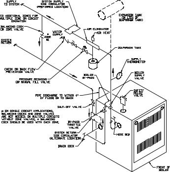
Table 2: Equivalent Length of Fittings
Fitting |
Nominal Pipe Size |
||||
|
|
|
|
||
½ |
¾ |
1 |
1¼ |
||
|
|||||
|
|
|
|
|
|
45° Ell |
0.7 |
1 |
1.2 |
1.6 |
|
|
|
|
|
|
|
90° Ell |
1.6 |
2.1 |
2.6 |
3.5 |
|
|
|
|
|
|
|
Tee (As Elbow) |
3.1 |
4.1 |
5.2 |
6.9 |
|
|
|
|
|
|
|
covered by Burnham's standard warranty.
There are many possible causes of oxygen contamination such as:
1.Addition of excessive make-up water as a result of system leaks.
2.Absorption through open tanks and fittings.
3.Oxygen permeable materials in the distribution system. In order to insure long product life, oxygen sources should be eliminated. This can be accomplished by
taking the following measures:
1.Repairing system leaks to eliminate the need for addition of make-up water.
2.Eliminating open tanks from the system.
3.Eliminating and/or repairing fittings which allow oxygen absorption.
4.Use of non-permeable materials in the distribution system.
5.Isolating the boiler from the system water by installing a heat exchanger.
10.INSTALL DRAFT HOOD without modification on outlet of flue collector (See Figure 1). Secure with sheet metal screws.
11. INSTALLBLOCKEDVENTSWITCH
The blocked vent switch assembly shipped taped to the top of the boiler includes a power cord and a switch attached to a mounting bracket. The mounting bracket has a three tooth staggered comb stamping at one end with a #10 sheet metal screw in the center tooth.
A.Untape the blocked vent switch assembly from the top of the boiler and uncoil the power cord.
B.Pinch the black strain relief bushing installed in the jacket right side panel to dislodge it from the jacket and pull just enough of the black power cord out so the blocked vent switch will reach the near side of the draft hood skirt. Do not pull out more power cord than necessary.
Table 3: Specific Gravity Correction Factors
Specific |
Correction |
Specific |
Correction |
Gravity |
Factor |
Gravity |
Factor |
|
|
|
|
0.50 |
1.10 |
1.30 |
1.07 |
|
|
|
|
0.55 |
1.04 |
1.40 |
1.04 |
|
|
|
|
0.60 |
1.00 |
1.50 |
1.00 |
|
|
|
|
0.65 |
0.96 |
1.6 |
0.97 |
|
|
|
|
0.7 |
0.93 |
1.7 |
0.94 |
|
|
|
|
0.75 |
0.9 |
|
|
|
|
|
|
0.8 |
0.87 |
|
|
|
|
|
|
C.Position the mounting bracket (with switch attached) onto the lower edge of the draft hood skirt by locating the center tooth (with the #10 sheet metal screw) on the outside and the other two teeth inside the draft hood skirt. See Fig. 6.
D.Slide the mounting bracket up tight against the lower edge of the draft hood skirt, so that the #10 sheet metal screw is above the skirt's stiffening rib.
E.Secure the bracket in this position by tightening the #10 sheet metal screw against the outer surface of the draft hood skirt.
F.Reinsert the excess power cord through the jacket side panel hole to take the slack out of the power cord running up to the blocked vent switch.
G.Reposition the strain relief bushing around the power cord at the jacket side panel, pinch the two halves of the bushing together, and snap it back into the hole in
7 |
Figure 3: Boiler Piping |
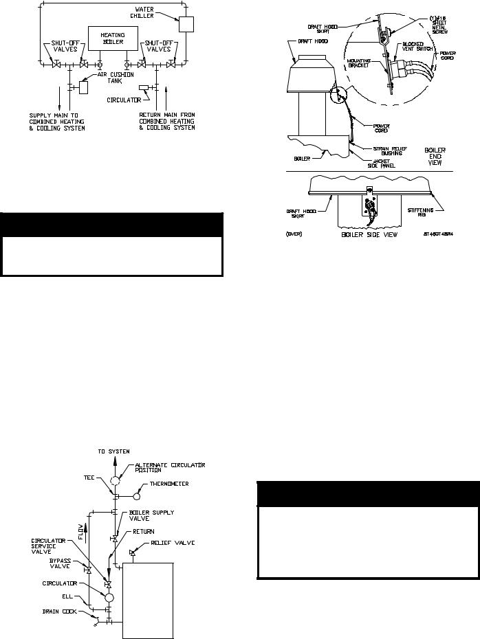
Figure 4: Recommended Piping for Combination Heating & Cooling (Refrigeration) Systems
the jacket side panel to secure the power cord to the jacket.
H.Be sure the power cord, mounting bracket, and switch are secure and located as shown in Figure 6.
WARNING
Failure to properly install and use this Blocked Vent Switch may result in property damage, personal injury or loss of life.
12. TOMEETFEDERALLYMANDATEDEFFICIENCIES, THISBOILERMUSTBEEQUIPPEDWITHAVENT DAMPER.
OPEN THE VENT DAMPER CARTON and remove the Installation Instructions. READ THE INSTALLATION INSTRUCTIONSTHOROUGHLYbeforeproceeding.
The automatic gas control valve supplied on each Series 2 boiler provides the reduncancy referenced in the vent damper Installation Instructions.
Figure 6
A.The vent damper should be the same size as the outlet of the Draft Hood. (See Figure 1) Unpack the damper carefully - DO NOT FORCE IT CLOSED! Forcing the damper may damage the gear train and void the warranty. The damper assembly includes a prewired connection harness for use on all 24V Standing Pilot or intermittent ignition control systems.
B.Refer to Figure 7 in this manual.
C.Mount the vent damper assembly on the draft hood without modification to either. (Refer to instructions packed with the vent damper for specific instructions). This is a must for the wiring harness to fit and the damper position indicator to be visible to the users.
NOTICE
Please refer to the specifications, installation instructions and troubleshooting guide packed in the vent damper carton for complete detailed installation instructions. Also refer to Figure 7 in this manual.
D. Install the 90° BX connector attached to the flexible conduit in the 7/8" knockout on the left side of the jacket. Plug the factory wired Vent Damper Harness into the polarized receptacle. Install a cable clamp around the flexible conduit and attach to the Jacket top panel. (See Figure 7).
Figure 5 |
8 |

E.Continuous Ignition (Standing Pilot) Only. Remove knockout from vent damper blade.
F.Size 202 Only. Install 4" x 3" reducing fitting on vent damper outlet (or draft hood outlet for Canadian boiler not equipped with vent damper).
13.INSTALL VENT CONNECTOR from reducing fitting (202 Only), draft hood or damper to chimney, see Fig. 8.
installed above the bottom of chimney to prevent blockage.
G.Vent pipe should slope upward from draft hood to chimney not less than one inch in four feet. No portion of vent pipe should run downward or have dips or sags. Vent pipe must be securely supported.
H.Vent pipe must be inserted into but not beyond inside wall of chimney liner. Seal tight between vent pipe and chimney.
I.Do not install non-listed (AGA, CGA, ETL or UL) vent damper or other obstruction in vent pipe.
14.IFANEXISTINGBOILERISREMOVED-
A.Vent installation shall be in accordance with local building codes; or the local authority having jurisdiction; or the National Fuel Gas Code, ANSI Z223.1/ NFPA 54; or the Standard for Chimneys, Fireplaces, Vents, and Solid Fuel Burning Appliances, ANSI/NFPA 211. Both of the aforementioned standards, ANSI Z223.1 and ANSI/NFPA 211, specify Type B and Type L double wall metal vents and fire clay tile lined masonry chimneys as suitable chimney constructions for Category I, draft hood equipped appliances, such as this Series 2 boiler. Both standards prohibit the use of unlined masonry construction as a chimney, with the exception in ANSI Z223.1/NFPA 54 that "Where permitted by the authority having jurisdiction, existing chimneys shall be permitted to have their use continued when an appliance is replaced by an appliance of similar type, input rating, and efficiency." ANSI/NFPA 211 prohibits the use of single wall metal vent as a chimney, while ANSI Z223.1 allows it under very restrictive conditions. In Canada refer to the Natural Gas Installation Code, CAN/CGA-B149.1 or the LP Gas Installation Code, CAN/CGA-B149.2 - latest edition.
B.Do not connect into same leg of chimney serving an open fireplace.
C.Inspect chimney for obstructions or restrictions and remove. Clean chimney if necessary.
D.Vent pipe to chimney must not be smaller than outlet on draft hood or damper. Although single wall vent pipe may be used, Type B is recommended. The venting system must be arranged so that only the boiler is served by the damper device. Installation per paragraph 12 complies with this provision.
E.Where two or more appliances vent into a common vent, the area of the common vent should at least equal the area of the largest vent plus 50% of the area in the additional vents. Do not connect the vent of this appliance into any portion of mechanical draft system operating under positive pressure.
F.Vent pipe should have the greatest possible initial rise above the draft hood consistent with the head room available and the required clearance from adjacent combustible building structure. Vent Pipe should be
9
When an existing boiler is removed from a common venting system, the common venting system is likely to be too large for proper venting of the appliances remaining to it.
At the time of removal of an existing boiler, the following steps shall be followed with each appliance remaining connected to the common venting system placed in operation, while the other appliances remaining connected to the common venting system are not in operation:
A.Seal any unused openings in the common venting system.
B.Visually inspect the venting system for proper size and horizontal pitch and determine there is no blockage or restriction, leakage, corrosion, and other deficiencies which could cause an unsafe condition.
C.Insofar as is practical, close all building doors and windows and all doors between the space in which the appliances remaining connected to the common venting system are located and other spaces of the building. Turn on clothes dryers and any appliance not connected to the common venting system. Turn on any exhaust fans, such as range-hoods and bathroom exhausts, so they will operate at maximum speed. Do not operate a summer exhaust fan. Close fireplace dampers.
D.Place in operation the appliance being inspected. Follow the Lighting (or Operating) Instructions. Adjust thermostat so appliance will operate continuously.
E.Test for spillage at the draft hood relief opening after 5 minutes of main burner operation. Use the flame of a match or candle, or smoke from a cigarette, cigar or pipe.
F.After it has been determined that each appliance remaining connected to the common venting system properly vents when tested as outlined above, return doors, windows, exhaust fans, fireplace dampers and any other gas burning appliance to their previous conditions of use.
G.Any improper operation of the common venting system should be corrected so the installation conforms with the National Fuel Gas Code, NFPA 54/ANSI Z223.1. When resizing any portion of the common venting system, the common venting system should be resized to approach the minimum size as determined using the appropriate tables in Part 11 in the National Fuel Gas Code, NFPA

Figure 7: Plug-in Damper Installation
10
54/ANSIZ223.1.
15. INSTALLAROOMTHERMOSTATonaninsidewall about four feet above floor. Never install thermostat on an outside wall or where it will be influenced by drafts, hot or cold water pipes, lighting fixtures, television, rays of the sun or near a fireplace. Keep large furniture away from thermostat so there will be free movement of room air around this control.
Heat Anticipator in Thermostat should be set to match the requirements of the control to which it is connected. See Table 4. If system tends to overheat above the thermostat's temperature setting, reduce heat anticipator setting by .1 or.2 amps. If system tends to short cycle without reaching desired room temperature, increase heat anticipator setting by .1 or .2 amps.
16.INSTALLELECTRICWIRINGinaccordancewith National Electric Code or the Canadian Electrical Code and local regulations. See Figures 11 through 14 for applicable wiring diagram. A separate Electrical Circuit should be run from meter with a Fused Disconnect Switch in this Circuit. When installed, the boiler must be electrically grounded in accordance with local codes or, in the absence of local codes, with the National Electrical Code, ANSI/NFPA 70, and/or the CSA C22.1 Electrical Code, if an external electrical source is utilized.
For zone valve wiring, a separate 24V transformer is required rather than attempting to use the boiler mounted control. Consult zone valve manufacturer for assistance.
17.VENTDAMPERSEQUENCEOFOPERATION
Effikal and Johnson Damper
|
Figure 8: Typical Vent Installation |
|
|
||
Table 4: Wiring Diagrams and Heat Anticipator Settings |
|
|
|||
|
|
|
|
|
|
|
|
Thermostat Heat |
Wiring Diagram |
||
Ignition Type |
Circulation Method |
|
|
||
Anticipator Setting [Amps] |
Figure Number |
Page Number |
|||
|
|
||||
|
|
|
|||
|
|
|
|
|
|
Continuous |
Intermittent |
0.6 |
11 |
13 |
|
(Standing Pilot) |
|
|
|
|
|
Constant/Gravity |
1.0 |
14 |
18 |
||
|
|||||
|
|
|
|
|
|
Intermittent |
Intermittent |
0.6 |
12 |
14 |
|
|
|
|
|
||
|
Constant/Gravity |
1.0 |
13 |
16 |
|
|
|
|
|
|
|
If system tends to overheat above thermostat's temperature setting, reduce heat anticipator setting by 0.1 or 0.2 amps. If system tends to shortcycle without reaching desired room temperature, increase heat
anticipator setting by 0.1 or 0.2 amps. |
11 |
|

A.The Vent Damper is continuously powered at Terminal 1.
B.When there is a call for heat, the damper relay coil is energized through Terminal 5 if all limits ahead of the damper are satisfied.
C.The relay coil closes contacts which energize the damper motor, causing the damper to open.
D.When the damper blade reaches the fully open position, power is sent back to the ignition circuit through Terminal 2 and the damper motor is de-energized.
E.When the call for heat is satisfied, the damper relay coil
is deenergized - closing contacts which energize the damper motor. This causes the damper to close. When the damper blade reaches the fully closed position, the damper motor is de-energized.
POWER FAILURE - The damper blade will stop in the position it was in when power failed. (Combustion can never take place unless the damper blade is in the fully open position.)
Figure 9: Vent Damper Schematic Wiring Diagram
12

Figure 11: Wiring Diagram, 24 Volt Standing Pilot and Intermittent Circulation
SEQUENCE OF OPERATION
NORMAL OPERATION
1.When the thermostat call for heat, the vent damper will open (see paragraphs 17A through 17D). The circulator is started through a relay and at the same time the gas valve is energized allowing main gas flow and ignition of main burners.
2.Where condensation of flue gas is encountered in boiler flues a reverse acting circulator control should be installed to stop the circulator before the boiler water temperature drops to that which flue gas condensation may occur.
3.After the thermostat is satisfied the main valve will close and main burner flames will be extinguished. The vent damper will close (see paragraph 17E).
SAFETY SHUTDOWN
1.High Limit Switch
In the event excessive boiler water temperature is developed the high limit switch will open interrupting power to the gas valve. The main burners will be extinguished immediately, and the vent damper will close at the same time, but the circulator will continue to operated. Normal operation will be resumed when the boiler water temperature drops to a point where the high limit switch closes.
2.Blocked Vent Switch
In the event excessive blockage in the vent system is developed the blocked vent switch will open interrupting power to the gas valve. The main burners will be extinguished immediately, the circulator will continue to operate, and the vent damper will remain open until the thermostat is turned off. The source of blockage must be corrected by trained and skilled personnel from a qualified service agency before resetting switch.
3.Flame Rollout Switch
In the event excessive blockage in the boiler section flue passageways is developed the flame rollout switch will open interrupting power to the gas valve. The main burners will be extinguished immediately, the circulator will continue to operate and the vent damper will remain open until the thermostat is turned off. If the flame rollout switch is activated do not attempt to place the boiler in operation. The source of blockage must be corrected and the flame rollout switch replaced by trained and skilled personnel from a qualified service agency.
4.Pilot
The thermocouple proves pilot flame and in the absence of such within 45-90 seconds causes the combination gas valve, which is equipped with a 100% shut-off provision, to be de-energized, thus, preventing main gas or pilot gas flow.
13

Figure 12: Wiring Diagram, Intermittent Ignition and Intermittent Circulation
14
SEQUENCE OF OPERATION
NORMAL OPERATION
1.When the THERMOSTAT calls for heat, the RELAY is energized. The CIRCULATOR starts and the VENT DAMPER is opened (see Paragraphs 17A through 17D). When the damper blade reaches the fully open position, the GAS VALVE powers the igniter circuit and opens the pilot valve.
2.The sensing circuit between the Q3450 or Q3480 pilot and the GAS VALVE proves presence of pilot flame.*
3.The GAS VALVE de-energizes the igniter and opens the main valve, allowing main gas to flow and ignition of main burners.
4.Where condensation of flue gas is encountered in boiler flues, a REVERSE ACTING CIRCULATOR CONTROL should be installed to stop the CIRCULATOR before the boiler water temperature drops to that at which flue gas condensation may occur.
5.The burners and CIRCULATOR will operate simultaneously until the THERMOSTAT is satisfied.
6.After the THERMOSTAT is satisfied the main valve, pilot valve and the circulator will be de-energized and main burner and pilot flames will be extinguished.
The VENT DAMPER will close (see Paragraph 17E).
SAFETY SHUTDOWN
1.High Limit Switch
In the event excessive boiler water temperature is developed the High Limit Switch will open, interrupting power to the VENT DAMPER and the GAS VALVE. Main Burners and Pilot Burner will be extinguished immediately. Normal operation will be resumed when the boiler water temperature drops to a point where the High Limit Switch closes.
2.Blocked Vent Switch
In the event excessive blockage in the vent system is
developed the blocked vent switch will open interrupting power to the VENT DAMPER and GAS VALVE. Main burners and pilot burner will be extinguished immediately, the VENT DAMPER will close and the CIRCULATOR will continue to operate. The source of blockage must be corrected by trained and skilled personnel from a qualified service agency before resetting switch.
3.Flame Rollout Switch
In the event excessive blockage in the boiler section flue passageways is developed the flame rollout switch will open interrupting power to the VENT DAMPER and the GAS VALVE. Main burners and pilot burner will be extinguished immediately. The VENT DAMPER will close and the CIRCULATOR will continue to operate. If the flame rollout switch is activated do not attempt to place the boiler in operation. The source of blockage must be corrected and the flame rollout switch replaced by trained and skilled personnel from a qualified service agency.
4.Pilot
A.Any pilot failure on the Q3450 or Q3480 Pilot will close the main gas valve and energize the igniter.
B.If the igniter breaks or becomes disconnected, the pilot valve coil loses power, closing the pilot valve.
5.For TROUBLE SHOOTING GUIDE, see Figure 28.
* · SV9500 and SV9600 Gas Valves:
The igniter and pilot gas valve will stay energized until either the pilot lights or the call for heat ends.
·SV9501 and SV9601 Gas Valves:
If the pilot fails to light after a 90 second trial for ignition, the igniter will be de-energized and the pilot gas valve will close. After a 5 minute delay, the igniter will be re-energized and the pilot gas valve will re-open. This continuous retry cycle will end either when the pilot lights or the call for heat ends.
15

Figure 13: Wiring Diagram, Intermittent Ignition and Continuous or Gravity Circulation
16
 Loading...